


Professional Shop Manual
300 Series Snow Thrower
NOTE: These materials are for use by trained technicians who are experienced in the service and repair of outdoor power equipment of the kind described in this publication, and are not intended for use by untrained or inexperienced individuals. These materials are intended to provide supplemental information to assist the trained technician. Untrained or inexperienced individuals should seek the assistance of an experienced and trained professional. Read, understand, and follow all instructions and use common sense when working on power equipment. This includes the contents of the product’s Operators Manual, supplied with the equipment. No liability can be accepted for any inaccuracies or omission in this publication, although care has been taken to make it as complete and accurate as possible at the time of publication. However, due to the variety of outdoor power equipment and continuing product changes that occur over time, updates will be made to these instructions from time to time. Therefore, it may be necessary to obtain the latest materials before servicing or repairing a product. The company reserves the right to make changes at any time to this publication without prior notice and without incurring an obligation to make such changes to previously published versions. Instructions, photographs and illustrations used in this publication are for reference use only and may not depict actual model and component parts.
© Copyright 2009 MTD Products Inc. All Rights Reserved
MTD Products Inc - Product Training and Education Department
FORM NUMBER - 769-05547
11/2009
Table of Contents
Chapter 1: Introduction ......................................................................................... |
1 |
About the text format . . . . . . . . . . . . . . . . . . . . . . . . . . . . . . . . . . . . . . . . . . . . . |
1 |
Safety . . . . . . . . . . . . . . . . . . . . . . . . . . . . . . . . . . . . . . . . . . . . . . . . . . . . . . . . |
2 |
Fasteners . . . . . . . . . . . . . . . . . . . . . . . . . . . . . . . . . . . . . . . . . . . . . . . . . . . . . . |
3 |
Assembly instructions . . . . . . . . . . . . . . . . . . . . . . . . . . . . . . . . . . . . . . . . . . . . |
3 |
Understanding model and serial numbers . . . . . . . . . . . . . . . . . . . . . . . . . . . . . |
4 |
The 300 series snow thrower . . . . . . . . . . . . . . . . . . . . . . . . . . . . . . . . . . . . . . . |
4 |
Chapter 2: Maintenance ........................................................................................ |
5 |
Engine maintenance . . . . . . . . . . . . . . . . . . . . . . . . . . . . . . . . . . . . . . . . . . . . . |
5 |
Auger / impeller maintenance . . . . . . . . . . . . . . . . . . . . . . . . . . . . . . . . . . . . . . |
5 |
Auger drive system maintenance. . . . . . . . . . . . . . . . . . . . . . . . . . . . . . . . . . . . |
6 |
Traction drive system maintenance . . . . . . . . . . . . . . . . . . . . . . . . . . . . . . . . . |
7 |
Chapter 3: Traction drive system ......................................................................... |
9 |
Description of the traction drive system . . . . . . . . . . . . . . . . . . . . . . . . . . . . . . |
9 |
Wheels and Tires . . . . . . . . . . . . . . . . . . . . . . . . . . . . . . . . . . . . . . . . . . . . . . . |
9 |
Tire Replacement . . . . . . . . . . . . . . . . . . . . . . . . . . . . . . . . . . . . . . . . . . . . . . . |
9 |
Drive Belt Replacement: Single-speed System . . . . . . . . . . . . . . . . . . . . . . . . |
10 |
Drive Belt Replacement: three speed drive system . . . . . . . . . . . . . . . . . . . . |
11 |
Drive Engagement Cable Replacement . . . . . . . . . . . . . . . . . . . . . . . . . . . . . |
15 |
Speed Control Cable Replacement . . . . . . . . . . . . . . . . . . . . . . . . . . . . . . . . . |
17 |
Transmission Removal . . . . . . . . . . . . . . . . . . . . . . . . . . . . . . . . . . . . . . . . . . |
19 |
Transmission Internals . . . . . . . . . . . . . . . . . . . . . . . . . . . . . . . . . . . . . . . . . . |
21 |
Chapter 4: Auger System.................................................................................... |
23 |
System Description . . . . . . . . . . . . . . . . . . . . . . . . . . . . . . . . . . . . . . . . . . . . . |
23 |
Auger belt removal . . . . . . . . . . . . . . . . . . . . . . . . . . . . . . . . . . . . . . . . . . . . . |
23 |
Auger control cable replacement . . . . . . . . . . . . . . . . . . . . . . . . . . . . . . . . . . |
25 |
Auger housing Removal. . . . . . . . . . . . . . . . . . . . . . . . . . . . . . . . . . . . . . . . . . |
28 |
Auger Housing disassembly: Pulley removal . . . . . . . . . . . . . . . . . . . . . . . . . |
29 |
Auger housing disassembly: Impeller shaft bearing replacement . . . . . . . . . . |
30 |
Auger housing disassembly: flight removal . . . . . . . . . . . . . . . . . . . . . . . . . . . |
32 |
Auger Housing disassembly: impeller brake replacement . . . . . . . . . . . . . . . |
34 |
Auger housing disassembly: Impeller removal . . . . . . . . . . . . . . . . . . . . . . . . |
36 |
Auger Transmission . . . . . . . . . . . . . . . . . . . . . . . . . . . . . . . . . . . . . . . . . . . . |
37 |
Chute . . . . . . . . . . . . . . . . . . . . . . . . . . . . . . . . . . . . . . . . . . . . . . . . . . . . . . . . |
39 |
I
II

INTRODUCTION
CHAPTER 1: INTRODUCTION
Professional Service Manual Intent: This manual is intended to provide service dealers with information that will help them maintain and repair the MTD 2-Stage snow thrower.
Disclaimer: The information contained in this manual is correct at the time of writing. Both the product and the information about the product are subject to change without notice.
About the text format
Certain flags and key words are used to indicate the nature of the text that accompanies them. They are as follows:
!CAUTION
!WARNING
!DANGER
CAUTION: Indicates a potentially hazardous situation that, if not avoided, may result in minor or moderate injury. It may also be used to alert against unsafe practices.
WARNING: Indicates a potentially hazardous situation that, if not avoided, could result in death of serious injury.
DANGER: Indicates an imminently hazardous situation that, if not avoided, will result in death or serious injury. This signal word is to be limited to the most extreme situations.
NOTE: “NOTE” is used to point-out helpful information that may not fit as a step in a procedure.
1.Numbered steps indicate specific things that should be done, and the order in which they should be done.
1a. Sub steps will be lettered and nested within steps. Two or more sub steps may be combined to describe the actions required to complete a step.
•Bullet points: Indicate sub-steps or points of interest, without implying order or relative importance.
Disclaimer: This manual is intended for use by trained, professional technicians.
•Common sense in operation and safety is assumed.
•In no event shall MTD be liable for poor text interpretation, or poor execution of the procedures described in the text.
•If the person using this manual is uncomfortable with any procedures they encounter, they should seek the help of a qualified technician.
1
INTRODUCTION
Safety
This Service Manual is meant to be used along with the Operator’s Manual. Read the Operator’s Manual and familiarize yourself with the safety and operational instructions for the equipment being worked on. Keep a copy of the Operator’s Manual for quick reference. Operator’s manuals may be viewed for free at the brand support website. It will be necessary to have the complete model and serial number for the equipment.
• Be prepared in case of emergency: Keep a fire extinguisher nearby Keep a first aid kit nearby
Keep emergency contact numbers handy
•Replace any missing or damaged safety labels on shop equipment.
•Replace any missing or damaged safety labels on equipment being serviced.
•Grooming and attire:
Do not wear loose fitting clothing that may become entangled in equipment. Long hair should be secured to prevent entanglement in equipment. Jewelry is best removed.
•Protective gear: includes, but is not limited to
Clear eye protection |
|
while working around any machinery |
|||||||||||
Protective gloves |
|
where necessary |
|||||||||||
|
|
|
|
|
|
|
|
|
|
|
|
|
|
Armored footwear |
|
when working around any machinery |
|||||||||||
Hearing protection |
|
|
in noisy environments |
||||||||||
Chemically resistant gloves |
|
|
|
when working with chemicals or solvents |
|||||||||
Respirator |
|
when working with chemical or solvents |
|||||||||||
Appropriate tinted eye protection |
|
|
|
|
|
when cutting or welding |
|||||||
Fame resistant headgear, jacket, chaps |
|
|
|
|
when cutting or welding |
||||||||
•Remember that some hazards have a cumulative effect. A single exposure may cause little or no harm, but continual or repeated exposure may cause very serious
harm.
•Clean spills and fix obviously dangerous conditions as soon as they are noticed.
• |
Lift and support heavy objects safely and securely. |
• |
Be aware of your surroundings and potential hazards that are inherent to all power |
|
equipment. All the labels in the world cannot protect a technician from an instant of |
|
carelessness. |
• |
Exhaust fumes from running engines contain carbon monoxide (CO). Carbon mon- |
|
oxide is a colorless odorless gas that is fatal if inhaled in sufficient quantity. Only |
|
run engines in well ventilated areas. If running engines indoors, use an exhaust |
|
evacuation system with adequate make-up air ventilated into the shop. |
!CAUTION
!CAUTION
!WARNING
!WARNING
!CAUTION
!CAUTION
!DANGER
2
INTRODUCTION
Fasteners
•The fasteners used on the equipment described in this manual, and the engine that powers it are a combination of metric and fractional inch. For this reason, wrench sizes are frequently identified in the text, and measurements are given in U.S. and metric scales.
•If a fastener has a locking feature that has worn, replace the fastener or apply a small amount of releasable thread locking compound such as Loctite® 242 (blue).
•Some fasteners like cotter pins are single-use items that are not to be reused. Other fasteners such as lock washers, retaining rings, and internal cotter pins (hairpin clips) may be reused if they do not show signs of wear or damage. This manual leaves that decision to the judgement of the technician.
Assembly instructions
•Torque specifications may be noted in the part of the text that covers assembly. They may be summarized in tables along with special instructions regarding locking or lubrication. Whichever method is more appropriate will be used. In many cases, both will be used so that the manual is handy as a quick-reference guide as well as a step-by-step procedure guide that does not require the user to hunt for information.
•Lubricant quantity and specification may be noted in the part of the text that covers maintenance, and again in the section that covers assembly. They may also be summarized in tables along with special instructions. Whichever method is more appropriate will be used. In many cases, the information will be found in several places in the manual so that the manual is handy as a quick-reference guide as well as a step-by-step procedure guide that does not require the user to hunt for information.
•The level of assembly instructions provided will be determined by the complexity of reassembly, and by the potential for damage or unsafe conditions to arise from mistakes made in assembly.
•Some instructions may refer to other parts of the manual for subsidiary procedures. This avoids repeating the same procedure two or three times in the manual.
3
INTRODUCTION
The 300 series snow thrower
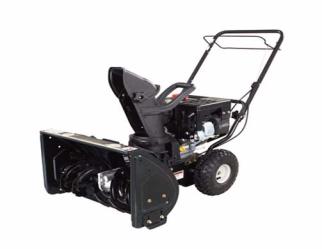
The 300 series snow thrower is designed for the residential user with moderate snow removal requirements
See Figure 1.0. Features:
•2-stage design
•Light-weight: 120 lbs. (54 kg.) typical
•22” clearing swath
•Self-propelled, with internal clutch transmission
•Some versions are single-speed
•Some versions have 3 ground speeds
Figure 1.0
Understanding model and serial numbers
The model number of a the snow thrower described in this manual is 31A-32AD762. This manual is likely to carry useful information for a range of similar Snow Throwers that may carry a variety of MTD and private brand names. The break down of what the model number means is as follows:
• |
31_ _ _ _ _ _ _ _ _ |
indicates that it is a snow thrower |
• |
_ _A_ _ _ _ _ _ _ _ |
indicates that is the first generation of its basic design |
• |
_ _ _ - _ _ _ _ _ _ _ |
indicates the type of starter ( - = recoil only, S = 110 V, M = 110 V+ alternator) |
• |
_ _ _ _32_ _ _ _ _ |
indicates the engine used |
• |
_ _ _ _ _A_ _ _ _ _ |
indicates the handle style |
• |
_ _ _ _ _ _D_ _ _ _ |
indicates the housing width (D= 22” (56 cm), E= 24” (61 cm) |
• |
_ _ _ _ _ _ _ _ 762 indicates the customer (styling, labels, color) |
|
The serial number is 1H126G10012. The serial number reads as follows: |
||
• |
1_ _ _ _ _ _ _ _ _ _ |
engineering level |
• |
_H_ _ _ _ _ _ _ _ _ |
month of production (A = Jan., B = Feb., C= March, D = April, E = May...) |
• |
_ _12_ _ _ _ _ _ _ |
day of the month |
• |
_ _ _ _6_ _ _ _ _ _ _ |
last digit of the year |
• |
_ _ _ _ _G_ _ _ _ _ |
plant it was built in (B= Willard, OH., G= Brownsville, TN., I= Canada) |
• |
_ _ _ _ _ _1_ _ _ _ _ |
assembly line number |
• |
_ _ _ _ _ _ _ _ 0012 |
Shift/sequence number |
Additional technical and service information is be available to our company authorized service center personnel through our corporate offices, regional parts distributors, and regional field support personnel. Please contact the designated support office in your area or our corporate offices directly should further service information is needed.
MTD Products LLC |
www.mtdproducts.com |
P.O. Box 368022 |
|
Cleveland, OH 44136 |
|
Telephone: (800) 800-7310 |
|
4
Maintenance
CHAPTER 2: MAINTENANCE
Proper maintenance and storage key factors in keeping outdoor power equipment dependable. Encourage your customers to bring snow equipment in for service and storage preparation at the end of each winter. Attending to their snow throwers maintenance in the early spring will bring-in some pre-season work and prevent the barrage of anxious phone calls when there is 8” of snow in their driveway.
Allow the engine to cool, and drain the fuel and oil from it before starting any mainte- ! CAUTION nance or service procedures.
Engine maintenance
All maintenance related material for the engine is covered in our horizontal shaft engine manual # 769-04015. Save engine storage preparation for last.
Auger / impeller maintenance
1.Inspect the augers for bending or damage.
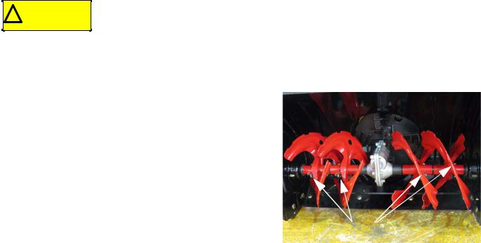
2.Inspect each shear pin;
2a. It is possible for a pin to be sheared, with one end stuck in place. Check both ends. Wiggle the auger to confirm that the shear pin is intact.
2b. Make sure that the shear pins have not ben replaced with standard clevis pins or nuts and bolts.
2c. Use only the correct OEM shear pins.
|
|
NOTE: Shear pins help prevent damage to the auger trans- |
Shear Pins |
mission if the augers hit a solid object hidden in the snow. |
|
NOTE: If a shear pin breaks, the unique design of the augers on current MTD snow throwers allows the next
auger over to continue driving the one with the broken shear pin. It is possible for a customer to continue clearing snow without noticing a damaged shear pin, but it will double the forces on the next shear pin.
NOTE: The auger gear box is sealed and filled with grease at the factory and should not require any maintenance or service.
3.Wiggle the auger shaft to check the shaft-end bearings in the auger housing. Replace the bearings if they are worn.
4.Check the auger drive transmission for any obvious damage. It is sealed a sealed unit, serviced by replacement of the complete transmission and auger shaft assembly.
5.Inspect the impeller;
5a. Wiggle the impeller to confirm that the roll pins that transfer drive from the input shaft are intact.
5b. The impeller should wiggle slightly, confirming that there are no foreign objects jammed behind the impeller.
NOTE: The typical customer complaint will be that the augers turn, but the snow just oozes out of the discharge chute.
5

MAINTENANCE
6.Spray penetrating oil on the joints between;
•The auger shaft and the bearings in the auger housing that support it
•the augers and the auger shaft
•the augers and the shear pins
•the impeller shaft and the impeller
7.Check and adjust the shave plate and the skid shoes;
7a. Replace the shave plate if it is worn. It is generally best |
|
|
to install the new shave plate with new carriage bolts |
Skid shoe |
Mounting bolts |
and locking nuts. |
|
|
7b. Replace the skid shoes if they are worn.
7c. Skid shoe adjustmentplace a length of corrugated cardboard under the shave plate, supporting the shave plate evenly about 1/4” (0.5cm) above the ground. Push the skid shoes down against the ground, then tighten the nuts that secure them.
|
|
Figure 2.2 |
Auger drive system maintenance |
||
|
|
Allow the engine to cool, and drain the fuel and oil from it before starting any main- |
|
|
|
|
! CAUTION |
tenance procedures. |
|
|
|
1.Remove the belt cover.
1a. Remove the screw on the right side of the of the belt cover using a 3/8” wrench.
1b. Squeeze the locking tabs inward and slip
the belt cover up and off of the snow thrower.
2.Tip the snow thrower up onto it’s auger housing.
3.Inspect the auger belt for signs of wear or damage.
4.Disconnect the auger brake spring with a piece of starter rope (the spring can be reached from the top, with the belt cover has removed).
5.Apply a film of with lithium grease under the auger brake
arm |
Figure 2.3 |
6.Work the brake arm back and forth to allow the grease to spread evenly under the arm.
7.Add a light film of oil to the brake spring.
8.Replace the auger brake return spring.
6
Traction drive system maintenance
NOTE: Be careful to keep oil and grease away from the belts and pulleys. NOTE: Replace any worn or damaged parts discovered during inspection.
NOTE: If a part has failed prematurely, identify and correct the cause of the failure.
1.Loosen the wheel bolts using a 1/2” wrench.
2.If not previously removed, take the belt cover off;
2a. Remove the screw on the right side of the of the belt cover using a 3/8” wrench.
2b. Squeeze the locking tabs inward and slip the belt cover up and off of the snow thrower.
3. Tip the snow thrower up onto its auger housing. 4. Inspect the moving parts of the system:
4a. Check the belts for wear or damage.
4b. Check the cables for wear or damage.
4c. Operate the traction clutch control bale; the cable and clutch should move smoothly.
4d. Check the traction belt tension pulley; it should rotate smoothly and keep adequate tension on the belt. 4e. Check the cross-shaft bearings; wiggle the shafts. There should not be more than .080” (2mm) play in the
|
shafts. |
When checking actuating or belt-tensioning mechanisms, do not place your fingers |
|
|
|
|
|
|
|
! CAUTION |
in an area where they might be pinched by unexpected movement. |
|
|
|
|
|
|
5.For 3-speed snow-throwers;
5a. Relieve tension from the traction drive belt by drawing-back the tension pulley.
5b. Operate the speed control lever; confirm that the variable-speed pulley moves and returns smoothly.
6.Apply grease to the two drive gears.
7.Apply a light coating of oil to the transmission tension spring.
8.Spray some penetrating oil into the area between any rotating shafts and the plain bushings that they ride in.
9.Lubricate the axles so that the wheels can be removed easily in the future: 9a. Remove the wheels.
9b. Apply a light coating of anti-seize grease to the axle. 9c. Replace the wheels.
9d. Install the wheel bolts and Belleville washers; the outer lip of the washer should taper inward to contact the outer edge of the axle.
9e. Tip the snow thrower back to its normal operating position. 9f. Tighten the wheel bolts to a torque of 20 in-lbs. (2.25 Nm).
10.Check and adjust the tire pressure to 20psi.
NOTE: The transmission is filled with gear oil and sealed at the factory. It is not intended to be serviced, and will require no maintenance.
7
MAINTENANCE
FINAL
1.Reinstall the belt cover.
2.Spray some penetrating oil into the points of the control cables where the cable core enters the cable housing.
3.Re-fill the crankcase with fresh 5W-30 engine oil, and add a small amount of fresh gasoline to the fuel tank.
4.Test-run the snow thrower, testing all operation and safety features.
5.Prepare the engine for storage;
•Drain or run all of the fuel out of the engine.
•Remove the spark plug and add a small amount of motor oil to the cylinder, then replace the spark plug.
•Turn the crankshaft 3-4 revolutions using the starter rope. Stop when there is tension on the rope, leaving both valves in the closed position.
8
TRACTION DRIVE SYSTEM
CHAPTER 3: TRACTION DRIVE SYSTEM
Description of the traction drive system
•A belt transfers power from the engine crankshaft to the input pulley of the transmission.
•A spring-loaded idler pulley keeps the belt under constant tension.
•On the three-speed version, a cable operated variable speed pulley changes the drive ratio to the transmission: the sheaves of the pulley close or spread to change its effective circumference. The idler pulley automatically compensates for the change in belt tension.
•The transmission is a sealed unit with an internal clutch. The clutch is actuated by a cable attached to the drive control bale on the handle.
•The transmission drives a 14T pinion gear which turns a 70T bull gear.
•The bull gear turns the axle at a 5:1 ratio from the transmission input shaft speed.
Wheels and Tires
IMPORTANT: The proper inflation pressure is a maximum 20 psi. See Figure 3.1.
Uneven air pressure between the two tires may result in:
•Uneven tire wear
•Irregular drive tracking
•Pulling from one side or the other
If you encounter a snow thrower with ! CAUTION plastic wheels, see Special Reminder
Service Advisory MTD-098.
NOTE: While it is possible to replace the tires on the wheels, they are generally serviced as an assembly.
Do not overinflate the tires.
! CAUTION
Tire Replacement
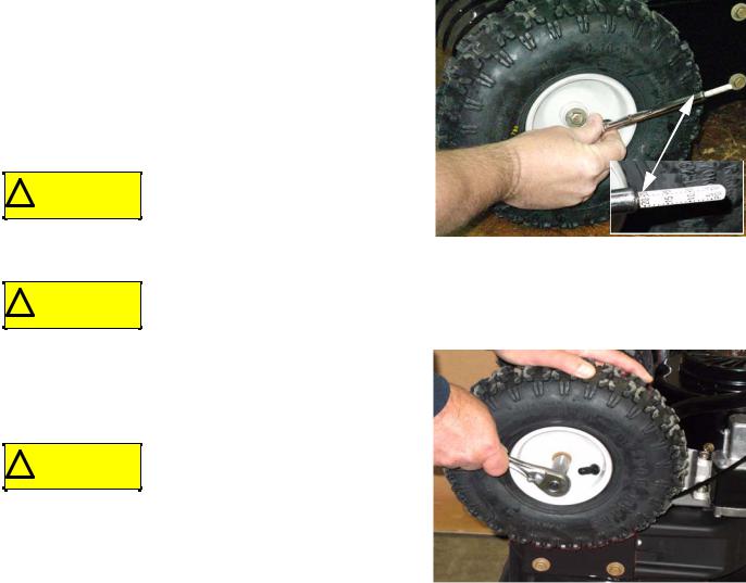
1.Loosen the bolts that hold the wheels to the axles using a 1/ 2” wrench. See Figure 3.2.
2.Tip the snow thrower forward onto its auger housing.
Allow the engine to cool, then drain
! CAUTION the fuel and oil from the engine before starting any service procedure.
3.Remove the bolts and slip the wheels off of the axles. NOTE: The wheels fit onto the axle with a double “D”.
4.On installation, lubricate the axle shaft with anti-seize.
5.Install the bolts and Belleville washers with the outer edge of the washers tapered in to meet the axle.
Air pressure gauge
Figure 3.1
Wheel bolt
Figure 3.2
9

TRACTION DRIVE SYSTEM
DRIVE BELT REPLACEMENT: SINGLE-SPEED SYSTEM
1.Remove the belt cover:
1a. Remove the screw on the right side of the belt cover with a 5/16” wrench or screwdriver. See Figure 3.3.
1b. Squeeze the locking tabs on the belt cover inward while lifting.
1c. Work the cover from between the engine and discharge chute
Allow the engine to cool, then drain
! CAUTION the fuel and oil from the engine before starting any service procedure.
Screw  Lock tab
2. |
Tip the snow thrower forward onto the auger housing. |
Figure 3.3 |
|
3.Remove the spring retaining nut from the anchor bolt on the side of the engine frame with a 7/16” wrench. See Figure 3.4.
4.Disconnect the extension spring that draws the transmis-
sion toward an anchor bolt on the engine frame from the Nut
anchor bolt.
Anchor bolt 

|
Figure 3.4 |
NOTE: Use a length of heavy cord looped around the hook |
|
end of the spring. See Figure 3.5. |
Starter rope |
|
|
|
Extension |
|
spring |
Figure 3.5
10
 Loading...