


Revision 1
April 2001
1-1
1-2
TABLE OF CONTENTS
INTRODUCTION ............................................ |
SECTION 1 |
COMPONENT DISCRIPTIONS ...................... |
SECTION 2 |
Battery Pack...................................................................... |
2-1 |
Battery charger.................................................................. |
2-2 |
Electric Drive Motor........................................................... |
2-3 |
Motor Controller ................................................................ |
2-3 |
Instrument Cluster............................................................. |
2-5 |
ELECTRICAL & CHEMICAL SAFETY ............ |
SECTION 3 |
High Voltage Safety .......................................................... |
3-1 |
Chemical Safety ................................................................ |
3-3 |
REMOVAL & INSTALLATION......................... |
SECTION 4 |
Canopy.............................................................................. |
4-3 |
Utility Bed.......................................................................... |
4-7 |
Motor/Speed Sensor ......................................................... |
4-9 |
Motor Contactor .............................................................. |
4-15 |
Controller ........................................................................ |
4-19 |
Battery Modules .............................................................. |
4-23 |
Battery Charger............................................................... |
4-29 |
Lights .............................................................................. |
4-33 |
Headlight, Horn, Hazard Light Switches.......................... |
4-35 |
Ignition Switch ................................................................. |
4-37 |
Turn Signal Switch .......................................................... |
4-39 |
Accelerator Pot (Throttle Sensor).................................... |
4-41 |
Instrument Cluster........................................................... |
4-43 |
Park Brake Switch........................................................... |
4-45 |
Brake Light Switch .......................................................... |
4-47 |
Horn ................................................................................ |
4-51 |
TEST PROCEDURES..................................... |
SECTION 5 |
Ignition Switch & Jumper Harness .................................... |
5-3 |
Accelerator Pot (Throttle Sensor)...................................... |
5-9 |
Motor............................................................................... |
5-11 |
Motor Contactor .............................................................. |
5-15 |
Speed Sensor ................................................................. |
5-19 |
Brake Switch ................................................................... |
5-21 |
Park Brake Switch........................................................... |
5-23 |
Directional Signal Switch................................................. |
5-25 |
Instrument Cluster........................................................... |
5-27 |
Charger ........................................................................... |
5-29 |
Battery Pack Evaluation .................................................. |
5-31 |
1-3
TROUBLESHOOTING .................................... |
SECTION 6 |
Fault Indication Table........................................................ |
6-2 |
Motor Will Not Operate...................................................... |
6-4 |
Nothing Works .................................................................. |
6-5 |
Will Not Operate In All Modes ........................................... |
6-6 |
Horn Does Not Work ......................................................... |
6-7 |
Battery Charger Does Not Operate ................................... |
6-7 |
Low Range........................................................................ |
6-8 |
Temperature Gauge.......................................................... |
6-8 |
Battery Gauge................................................................... |
6-8 |
Speedometer Does Not Work ........................................... |
6-9 |
Instrument Cluster LED Indicators .................................. |
6-10 |
Headlights & Taillights..................................................... |
6-11 |
Rear Lights...................................................................... |
6-12 |
Front Lights ..................................................................... |
6-12 |
Hazard Lights .................................................................. |
6-13 |
Brake Lights .................................................................... |
6-13 |
Directional Signals .......................................................... |
6-14 |
Twist Lock Connector Pinouts......................................... |
6-15 |
1-4
SECTION 1: INTRODUCTION
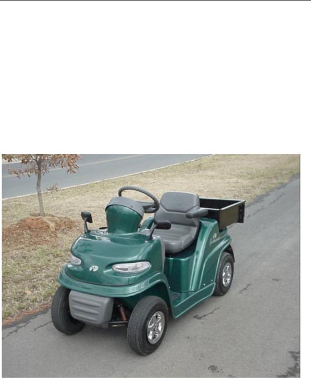
The FunRunner is an all-electric utility vehicle. The energy for the FunRunner’s propulsion as well as the operation of its lights, instruments, horn, and etc., come from its 48-volt battery pack. Being electric, the FunRunner emits no exhaust and is therefore a zero emissions vehicle. It is an environmentally friendly vehicle. The FunRunner is also much quieter than an internal combustion vehicle. It is well suited for use in areas that are considered noise sensitive or indoors where harmful gasoline emissions are a concern.
Because gasoline powered vehicles have electrical systems for cranking, ignition, lights,
Figure 1-1: FunRunner
etc., some of the service procedures used with them are similar to those used with the FunRunner. Other procedures will be unique to the FunRunner.
The main components of the FunRunner are the battery pack, electric motor, controller, battery charger, and instrument cluster. The FunRunner uses a 48V battery pack that is considered to be high voltage. The high voltage can be dangerous and requires an extra measure of safety procedures not normally associated with the service of gasoline vehicles and equipment.
1-1
1-2
SECTION 2: COMPONENT DESCRIPTION
Battery Pack
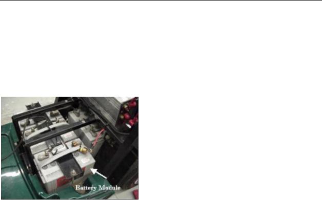
The battery pack of the FunRunner consists of four 12-volt sealed lead acid battery modules. The modules are situated in the vehicle under the seat and are covered by the rear body panel. See Figure 2-1. Since the modules are sealed and valve regulated, no water or electrolyte can be added to the batteries.
Figure 2-1:
Each module has a rated capacity of 73 amperehours (Ah) at a 20-hour discharge rate and 48 Ah at the 1-hour discharge rate. The capacity is the available quantity of electricity in a battery measured in Ah. Capacity is always related to some quantity of current in amperes (amps) and the length of time that the given current can be produced. The minutes of reserve is a capacity rating in which the amount of current is set at a given rate, usually 25 amps, then the length of time it takes for the battery to reach its discharged cut-off voltage is measured. This amount of time in minutes is the reserve capacity of the battery.
For an electric vehicle like the FunRunner, the capacity available from the batteries determines the range of the vehicle. The range is the distance that can be driven on one battery charge.
The normal driving range of the FunRunner is approximately 30 miles when the batteries are performing at their rated capacity. The battery capacity and therefore the range can be affected by several factors however.
Temperature has a dramatic effect on a lead acid battery’s capacity. The standard
temperature for rating a battery is 78° F. At temperatures above 78° F, the capacity will be higher than the rated capacity. The capacity will be lower than rated capacity when temperatures are below 78° F. At 32° F only about 70 percent of the rated capacity is available. This is significant, because if the FunRunner is operated when the temperature is around 32° F, the range will be reduced by 30 percent.
Another factor effecting capacity is the rate of discharge. The battery modules in the FunRunner are rated at 73 Ah for the 20-hour rate and 48 Ah for the 1-hour rate. That’s a large difference in the available Ah’s produced between the two discharge rates. At the 20-hour rate, the current drawn from the battery is set to a low value that will take 20 hours to bring the battery down to its cut-off voltage. The rate of current in amps times the 20 hours is the capacity rating. At the 1-hour rate, the current is set at a much higher rate to bring the battery down to the cut-off voltage in one hour. With a 73 Ah rating for 20 hours and a 48 Ah rating for 1 hour, it is obvious that the higher the rate of current draw, the lower the capacity.
The FunRunner will use current at a fairly high rate, and the higher the rate the shorter the range will be. If it is driven faster or up hill frequently, then the current rate will be higher and the capacity of the battery pack will be reduced.
The normal chemical process in the battery over time will reduce the amount of active material on the plates of the battery. This reduction in active material will cause a reduction in capacity. In other words, as the battery ages and more and more charge/discharge cycles have occurred, the capacity of the battery will begin to decrease. When the aging process of the battery has caused a decrease in capacity so that the FunRunner no longer has a useable range, the batteries must be replaced.
The four battery modules of the FunRunner are wired in series to form a 48-volt battery pack. When connecting battery modules in series, the voltage of the pack is the total of the modules in the series string. See Figure 2-2.
2-1
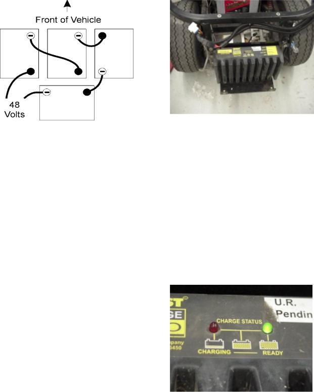
Figure 2-2:
The modules must be connected from the positive terminal of one module to the negative terminal of the next. The one positive and one negative terminal remaining on the modules are the main terminals. The voltage at the main terminals is 48V nominal.
When battery modules are connected in series, the voltage of the system is added (i.e. 48 volts) and the capacity of the modules not added. The capacity of the series string is equal to the capacity of one module. In fact, the capacity of the series string is actually equal to the module with the least capacity. However, because the voltage is four times higher, the power and energy of the pack is four times that of one module.
As the capacity of the battery is reduced by the various factors, the power of the battery is normally not effected. The energy (power used over time) is reduced however. This means that no loss of speed, acceleration, or feel of power will be experienced when a battery pack’s capacity is reduced. A battery pack with only 15 Ah capacity will have the same power as one with 48 Ah capacity when both are fully charged. What will be noticed is a reduction in the range of the vehicle.
Battery Charger
The FunRunner has an on-board battery charger located at the rear of the vehicle just in front of the rear bumper. See Figure 2-3. The function of the charger is to replenish the used energy from the battery pack.
Figure 2-3:
The charger receives its power from a 110 VAC outlet when a cord is plugged into the charger input connector located in the front of the rear body panel below the seat. The AC power is converted to DC and conditioned to the proper voltage and current output levels to charge the battery. It will take the charger about 7-8 hours to restore a battery pack from fully discharged to fully charged.
Located on the top of the battery charger are one green and one red LED. See Figure 2-4. During charging, the red LED is illuminated.
When the battery pack reaches a full charge, the green LED will come on and the red LED will go out. These LED indicators are not visible unless the trunk basket panel is removed. The battery charge gauge on the instrument panel cluster is the indicator normally used for state of charge reference.
Figure 2-4:
The battery charger is designed to never overcharge or overheat the batteries due to prolonged charging. Leaving the charger plugged in will allow it to maintain a full charge
2-2
without overcharging. It is desirable to leave the charger plugged in for long periods periodically to equalize the charge of the battery pack modules. Doing this will increase battery life.
Electric Drive Motor
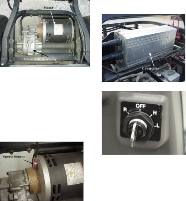
The FunRunner uses a 48-volt brush type DC motor. The motor uses permanent magnets for the field and has a wound armature with a commutator that the brushes ride on. See Figure 2-5.
Figure 2-5:
The motor is connected to the rear wheels through a fixed ratio drive axle with differential. Reverse for the FunRunner is accomplished by reversing the direction of rotation of the electric drive motor. There are no reverse gears in the drive assembly. The motor receives power from the controller.
The motor has no serviceable parts and is replaced as an assembly if it fails. There is a speed sensor located on the spacer between the motor and drive axle. The speed sensor is supplied as a service part. See Figure 2-6.
Figure 2-6:
Motor Controller Assembly
The motor controller assembly on the FunRunner is located just ahead of the trunk basket panel under the rear body section. See Figure 2-7. The controller is rated at 150 amps and 48 volts. It is a four-quadrant controller that uses pulse width modulation. The four-quadrant design allows the motor to be reversed, eliminating the need for a mechanical reverse gear. The pulse width modulation ensures smooth acceleration and power delivery while operating at an extremely high efficiency level.
Figure 2-7:
Figure 2-8:
The controller can be switched to either high or low forward speeds or reverse. See Figure 2-8. When selected to high speed, the controller will allow a maximum speed of 12 mph. In low speed mode, the controller will reduce the output voltage as needed to reduce the max speed to 8 mph. Reverse mode is 6 mph maximum.
2-3
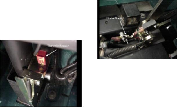
Of course, the controller must be able to provide fully variable speed in each drive mode. The throttle sensor is attached to the accelerator pedal assembly and wired as an input to the controller. See Figure 2-9. The sensor is a potentiometer (a type of variable resistor often called a pot) that will give a continually variable signal from the fully released to fully depressed pedal positions.
Figure 2-9:
The controller will monitor the throttle sensor signal and adjust the output voltage to the motor according to the demands of the operator through the accelerator pedal.
The controller is also equipped with regenerative braking. Regenerative braking is a feature where the motor becomes a generator when the vehicle is coasting or stopping. The kinetic energy of the vehicle is turning the armature of the motor through the permanent magnet field producing a current in the armature that goes to the controller. The current produced is opposite of that used by the motor to drive the vehicle. The controller will pass this current to the battery pack replenishing a small portion of its charge. The regenerative braking provides two benefits: it increases range by adding some charge to the battery pack and provides braking action that assists the mechanical brakes. You can feel the regenerative braking when releasing the accelerator even if the brake pedal is not depressed.
The brake switch is connected to the controller so that when the controller sees an input indicating the brake has been depressed, it will not allow power to flow to the motor even if the accelerator pedal is depressed. See Figure 2-10.
Figure 2-10:
A signal is sent from the charger to the controller during charging of the FunRunner. When the controller senses the charging signal, none of the propulsion modes can be activated. The output from the charger passes thru the controller to the batteries.
The FunRunner’s motor controller is unique in that it controls all of the electrical systems on the vehicle in addition to the motor. The controller supplies power to each electrical system when an input to the controller for the particular system is activated. You can think of the controller as a relay for each system. It operates in a manner similar to a starter relay connecting power to the starter when the ignition or start switch energizes the coil of the relay.
An example of this would be the headlights. The controller sends a voltage to the headlight switch and monitors this voltage to see if it is returned (pulled low) by the switch. When the headlight switch is turned on, it closes connecting the voltage to the return and the controller sees the headlight switch wire pulled low. The controller responds by supplying 12 volts to the headlight and taillight bulbs. The headlight switch does not feed power directly to the lights.
Other systems such as turn signals, brake lights, hazard lights, horn, parking brake indicator and etc., are controlled in the same way. These are systems activated by the person operating the vehicle. The controller will give outputs to other electrical systems based on inputs not activated by the operator. Examples are the state of charge gauge and the speedometer. The controller will adjust the state of charge meter based on battery pack voltage. The controller
2-4
will output a signal to the speedometer based on an input from the speed sensor.
All of the controller inputs and outputs are shown in Figure 2-11. The diagram shows how
the controller is the master of the electrical systems on the FunRunner.
Figure 2-11
Instrument Cluster
The instrument cluster has three indicator gauges across the top and several LED indicators along the bottom of the cluster. See Figure 2-12. The cluster is the information center for the operator.
The center gauge is a speedometer with odometer. The temperature gauge is on the left and it displays the temperature of the controller heat sink. The battery gauge is on the right side and it displays the state of charge of the battery pack.
The fault, temperature, battery, reverse, on, high, low, charging, park brake, and headlights indicators make up the bottom row of LED’s. Above these indicator lights are the turn signal indicators. These lights will illuminate when the corresponding signal of its function is activated. The fault, battery, charge, and temperature indicators and an audible beep from the controller are used to relay fault codes.
Figure 2-12:
2-5
2-6
SECTION 3: ELECTRICAL AND CHEMICAL SAFETY
Electrical safety is foremost on the FunRunner, since voltage levels present can cause severe burns, shock, or death.
High voltage electric shock can cause muscle contractions. A current of only 10mA can cause muscles to contract. Hands that are exposed to enough electrical current clinch tight and cannot release their grip.
Even a small amount of current can cause body tissue damage. Damage to tissue is caused by heat generated from current flow. When the heat passes a point where it can be dissipated, the body tissue is burned.
Fibrillation, the disruption of the body’s normal heartbeat, can be caused by electrical shock. The current must pass through the body, such as with a hand-to-hand connection, in order for fibrillation to occur.
Arcing occurs when electricity is discharged across a circuit gap. The heat at the ends of an arc can be four times the surface temperature of the sun. Severe burns can be caused when a person is near or in contact with an arc.
An arc can cause an electric blast. The blast is the expansion of the air and molten metal, usually copper, from the rapid heating taking place.
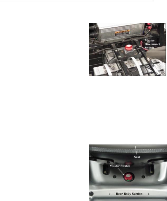
The FunRunner is equipped with a master disconnect switch. See Figure 3-1.
Figure 3-1:
The master switch is a safety device that allows the battery pack voltage to be removed from the controller. The switch is to be used to disconnect the battery from the controller before starting any repairs to the high voltage portion of the vehicle.
The master switch is located behind the seat. See Figure 3-2. It can be turned off by sliding the seat forward, reaching behind the seat and twisting the red knob. The knob can be pulled off of the switch when in the off position to ensure that it is not inadvertently turned back on.
High Voltage Safety Procedures
The FunRunner’s high voltage and low voltage systems are isolated from chassis ground under normal circumstances. You must touch both a positive and negative point in the circuit in order to receive an electric shock. You should never ground any wire on the FunRunner to the chassis. Doing so could put the operator and any service personnel in danger.
Figure 3-2:
The FunRunner has high voltage in the propulsion, charging and ignition switch circuits. See Figure 3-3.
3-1
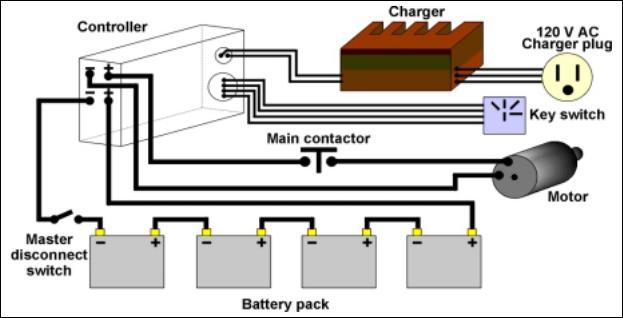
Figure 3-3: FunRunner High Voltage Wiring
Practicing safety around high voltage (HV) will protect you and those around you. Keep in mind the following HV safety precautions:
•Have ample light in the work area.
•Do not work in wet or damp areas.
•Use proper tools, equipment, and protective devices.
•Remove all jewelry and metallic items.
•Keep your tools and equipment in good condition.
•Never assume that voltage is not present; check it with a known good meter or other test device.
•Verify that any capacitors have been discharged.
•Never try to bypass or override a safety device, such as a fuse, unless specified to do so with an approved tool as described by the manufacturer’s procedures.
•Always use the correct replacement parts.
•Never use water on an electrical fire; have an approved fire extinguisher available.
•Use only one hand when possible.
•Wear eye protection.
•Never work on high voltage when you are totally alone; someone else should be present in case an emergency arises.
•Follow the manufacturer’s procedures.
•Take your time, think first and do not rush.
•Know emergency policies and procedures for your work area.
•Wear natural fabric clothing such as cotton; polyester clothing will melt to the skin when exposed to electrical arcs.
•Use insulated tools and inspect them regularly for damaged insulation.
•Know where eyewash stations, fire extinguishers, reach poles and other safety equipment is located.
•Never lay tools or any conductive material on any HV component or battery pack.
The longer someone is in contact with an electrical current, the less chance there is for survival. The victim may stop breathing and become somewhat stiff. In the case of electrical shock, the following procedures should be followed:
•Call 911 or the appropriate emergency numbers for your area.
•Break the electrical connection as quickly as possible, but do not expose yourself to any electrical current.
•If the current cannot be removed, use a fiberglass reach pole or a dry board to separate the victim from the circuit. Do not touch the victim with your bare
3-2
hands until you are sure they have been removed from the electrical current.
•If the victim has stopped breathing or his/her heart is not pumping, use CPR until help arrives. Only a trained person should administer CPR.
•If the victim must be moved, take precautions in doing so. Use a stretcher if possible.
Fire is always a possibility when working on an electric vehicle. High voltage and chemical batteries have the potential to cause both fire and explosion when a faulty condition exists.
Work areas should be clean and not cluttered with combustible materials. Flammable liquids should be stored in approved storage areas.
You should know the location of fire extinguishers and fire alarms. You should also know how to contact the fire department. Make sure you know how to operate the fire extinguishers and what type of fire they are rated for. Figure 3-4 shows the classes of fires. Fire extinguishers should be inspected monthly to verify they have a full charge.
Figure 3-4:
Chemical Safety
Batteries in the FunRunner contain electrolyte that is very corrosive. Contact of electrolyte with skin or eyes should be avoided.
The FunRunner uses sealed batteries that contain electrolyte in a gel between the plates. While these types of batteries cannot spill large amounts of electrolyte, care should still be taken to avoid chemical contact with the skin and eyes.
When working around batteries where there is the possibility of chemical exposure, eye protection should be worn, rubber gloves and a rubber apron are recommended. An emergency shower and eye wash station should be available as well as a first-aid kit and electrolyte neutralizing solutions.
Lead acid batteries have a sulfuric acidwater solution as the electrolyte. Sulfuric acid is very corrosive and can burn skin and
eyes. The neutralizing agent for sulfuric acid is bicarbonate soda. One pound of soda dissolved in one gallon of water makes a good neutralizing solution that can be used in a spray bottle or poured on a spill.
When sulfuric acid contacts the skin, eyes, or clothing, the first line of defense is water and plenty of it. Flush the area with clean water and soda mixture for 15 minutes. If there is not enough soda-water mixture to flush for 15 minutes, continue to flush with clean water for a minimum of 15 additional minutes and get prompt medical attention.
If acid is accidentally swallowed, drink large quantities of milk or water, followed by milk of magnesia, a beaten egg, or vegetable oil. Consult a physician immediately.
3-3
3-4

SECTION 4: REMOVAL & INSTALLATION
Canopy................................................................ |
4-3 |
Utility Bed ............................................................ |
4-7 |
Motor/Speed Sensor ........................................... |
4-9 |
Motor Contactor ................................................ |
4-15 |
Controller .......................................................... |
4-19 |
Battery Modules ................................................ |
4-23 |
Battery Charger................................................. |
4-29 |
Lights ................................................................ |
4-33 |
Headlight, Horn, Hazard Light Switches ............ |
4-35 |
High/Low/Reverse Switch.................................. |
4-37 |
Turn Signal Switch ............................................ |
4-39 |
Accelerator Pot (Throttle Sensor) ...................... |
4-41 |
Instrument Cluster ............................................. |
4-43 |
Park Brake Switch ............................................. |
4-45 |
Brake Light Switch............................................. |
4-47 |
Horn .................................................................. |
4-51 |
4-1
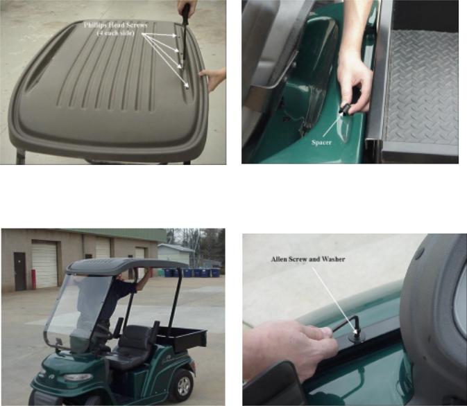
Figure 4-1 |
Figure 4-1A |
Figure 4-2 |
Figure 4-3 |
4-2
SECTION 4: CANOPY INSTALLATION & REMOVAL
PARTS REQUIRED |
TOOLS REQUIRED |
710-0642 Hex Washer Screw 1/4-20 x .75 (8) |
Phillips head screwdriver - #2 |
736-0342 Flat Washer .283 ID x .75 OD (12) |
|
731-2337 Canopy Panel |
3/16” Allen wrench |
749-1265 Rear Canopy Frame |
|
749-1266 Front Canopy Frame |
Note: you may need one person to help. |
710-0136 Hex Cap Screw 1/4-20 x 1.75 (2) |
|
710-1122 Hex Cap Screw 1/4-20 x 2.5 (2) |
|
750-1298 Spacer .280 ID x 437 OD x .250 Lg (2) |
|
750-1299 Spacer .280 ID x 437 OD x .850 Lg (2) |
|
|
|
|
|
STEP |
DETAILS |
|
|
Get tools and check parts. |
See list above. |
|
|
Assemble molded canopy and supports |
Align screw holes with holes in supports. |
(Figure 4-1). |
|
|
Install and tighten Hex washer screws with |
|
flat washers through canopy into threaded |
|
holes in supports. |
|
|
Install canopy and support assembly. |
Remove two cap plugs on top of body just |
Note: Nylon bushings are installed between |
behind seating area. |
|
|
the vehicle body and the threaded screw |
Remove two Allen screws and spacers on |
holes used to fasten the canopy supports. |
top of body directly in front of the dash. |
Be careful to place bushings in position |
|
properly. |
Insert the shorter spacers in the front holes |
Note: Screws have spacers under |
and the longer spacers in the rear holes. |
|
|
canopy supports that must be installed to |
Gently set canopy/support assembly on |
protect body from deflection (Figure 1A). |
vehicle with curved end facing to the front. |
|
(Figure 4-2). |
|
Insert and tighten Hex cap screws with flat |
|
washers in front and rear supports. Tighten |
|
to 65 to 75 in. lbs. (Figure 4-3). |
|
|
Save extra parts. |
Store Allen screws for use if top is removed. |
|
|
|
|
4-3
4-4
Remove canopy assembly. |
Remove 4 Hex cap screws from supports and |
|
set canopy assembly aside. |
|
Remove spacers and store screws. |
|
If canopy assembly is not to be replaced, place |
|
cap plugs in rear body section and install |
|
original Allen screws and spacers in front body |
|
panel |
|
|
Remove molded canopy. |
Remove 8 Phillips head, ¼” x ¾” screws from |
|
canopy. |
Note: If canopy is to be re-installed, this step |
Lift canopy from supports and set aside. |
is not necessary. |
|
|
Store screws for replacing canopy. |
|
|
|
|
4-5
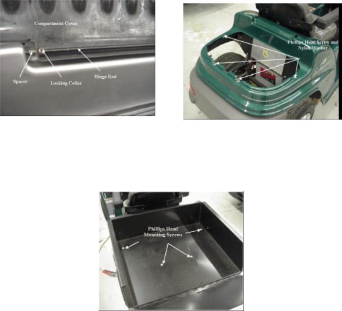
Figure 4-4 |
Figure 4-5 |
Figure 4-6
4-6
UTILITY BED INSTALLATION
PARTS REQUIRED |
TOOLS REQUIRED |
607-0013 Utility Box Assembly |
#2 Phillips screwdriver |
710-1832 Machine Screw 1/4-20 x 2” (4) |
1/16” Allen wrench |
736-0173 Flat Washer .28 ID x .74 OD (4) |
|
|
|
|
|
STEP |
DETAILS |
|
|
Remove rear trunk lid and trunk basket |
Raise cover so hinge rod is visible. |
(Figure 4-4). |
|
|
Loosen 1/16” Allen set screw on each hinge rod |
|
locking collar. |
|
Slide hinge rod toward one side to remove rod, |
|
spacers and trunk lid. |
|
Be careful not to loose spacers. Remove trunk |
|
basket. |
|
|
Remove body retaining screws |
Remove 4 Phillips head screws and washers |
(Figure 4-5). |
holding body to frame around storage area. |
|
Disconnect trunk lock from back of vehicle by |
|
removing the two cap screws. |
|
Store screws for possible future use. |
|
|
Install utility bed (Figure 4-6). |
Place bed on frame so tailgate is to the rear. |
|
Line up holes in bed with holes in frame. |
|
Install 4 screws and flat washers provided |
|
through bed into frame. |
|
Tighten screws to 40-45 in. lbs. and check bed |
|
secure. |
|
|
Clean up. |
Store parts and tools. |
|
|
|
|
4-7
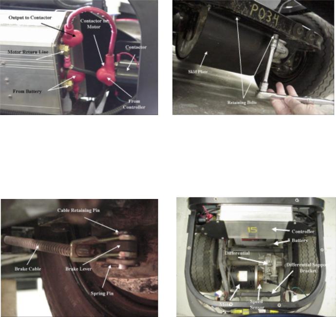
Figure 4-7 |
Figure 4-8 |
Figure 4-9 |
Figure 4-10 |
4-8

MOTOR/SPEED SENSOR REMOVAL & INSTALLATION
TOOLS REQUIRED
Wrenches - 3/8”, 1/2”, 9/16”, and 5/8” - socket and box end preferred Pliers
Lift or jack - suitable for raising rear of vehicle and being clear when axle/wheel assembly is slid out to the side.
Phillips screwdriver - #2 Allen wrench – 3/16”
STEP |
DETAILS |
Make vehicle safe and accessible.
WARNING:
IF MASTER POWER SWITCH IS NOT OFF BATTERY IS STILL CONNECTED TO CONTROLLER. USE EXTREME CARE TO AVOID INJURY OR DAMAGE.
Make sure switch is off and key removed.
Place chocks under all 4 wheels, front and back of each wheel if any chance of rolling.
Remove utility bed if installed (4 screws). Remove storage compartment.
Turn master power switch to off. |
Key operated switch mounted below |
|
controller. |
Disconnect motor cables from contactor and |
Disconnect motor lead from motor side of |
controller (Figure 4-7). |
contactor. |
Note: use care that washer or nut cannot fall |
Move controller as necessary to reach left side |
into motor. |
power cable terminals. |
|
Disconnect top-front power cable on left side |
|
of controller (goes to motor). |
|
Front cable connected with 9/16” nut and star |
|
washer. (rear cable connected with 5/8” nut |
|
and star washer. Do not remove for this step). |
|
|
Remove skid plate (Figure 4-8). |
From under motor. |
|
Fastened to frame in front and rear of motor |
|
with 4 screws, ¼” x ½” with 3/8” hex head. |
|
|
Disconnect brake cables (Figure 4-9). |
From rear brake levers, right and left rear |
|
wheels. |
|
Pull spring pins from brake cable retaining |
|
pins. |
|
Lift retaining pins from cable shackles. |
|
|
Disconnect speed sensor. Unfasten differential |
Unplug (plug in line inside rear compartment). |
support bracket (Figure 4-10). |
Bracket is bolted to frame with two large |
|
washers on outside of frame. |
|
|
|
|
4-9

Figure 4-11 |
Figure 4-12 |
|
Figure 4-13 |
Figure 4-14 |
|
Figure 4-15
4-10
Warning: |
|
After axle assembly is completely loosened, |
|
motor can fall and catch a hand unless care |
|
is used. Suggest a block be placed under |
|
differential bracket before axle is completely |
|
loosened. |
|
Disconnect motor support bracket |
Bolted to motor and frame on left side of |
(Figure 4-11). |
vehicle. |
|
2 bolts, ¼” x ½” - need 3/8” wrench. |
|
|
Remove axle mounting brackets |
Need ½” box end and ½” ratchet wrenches. |
(Figure 4-12). |
|
Slide axle assembly from under vehicle |
Attach lift to rear of frame, or use floor jack, |
(Figure 4-13). |
and raise vehicle high enough to slide rear |
|
axle/motor assembly out to side. |
|
Place supports under rear of battery pack to |
|
be sure vehicle cannot fall. |
|
|
Remove motor (Figure 4-14). |
Place support under motor. |
|
Use 3/16” Allen wrench to remove two |
|
mounting screws. |
|
Tilt rear of motor down and remove from drive |
|
axle. |
|
|
Remove parts from motor. |
Slide coupler and speed sensor cog from |
|
motor shaft. |
|
Remove motor support bracket -two bolts - |
|
3/8” wrench. |
|
Loosen 1/8” Allen screw in end of spacer and |
|
unscrew speed sensor. |
|
|
Install parts on new motor (Figure 4-15). |
Bolt motor support bracket to new motor. |
|
Insert speed sensor cog and coupler into |
|
spacer and onto new motor shaft. |
|
Install speed sensor in spacer. |
Set speed sensor depth. |
Make sure speed sensor cog is inserted on |
|
motor shaft |
|
Screw speed sensor into spacer until it |
|
touches cogs on sensor gear. |
|
Unscrew speed sensor ¾ to 1 turn and make |
|
sure it does not touch cogs when motor turns. |
|
Tighten set screw to lock speed sensor in |
|
place. Caution: do not over tighten set screw |
|
causing damage to sensor threads. |
|
|
4-11
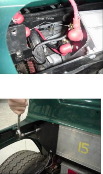
Figure 4-16
Figure 4-17
4-12
Install new motor on axle assembly. |
Place motor on support so differential can be |
|
rotated and lined up with motor. |
|
Mate motor to differential with speed sensor |
|
pointing away from axle. Make sure speed |
|
sensor cog and coupler are in place. |
|
Replace motor mounting screws using 3/16” |
|
Allen wrench. Tighten securely. |
|
|
Mount axle assembly on vehicle. |
Slide assembly under rear of vehicle and |
|
locate close to proper position. |
|
Place block under differential support bracket |
|
so bracket will be in position when vehicle is |
|
lowered. |
|
Lift vehicle slightly and remove supports from |
|
under battery pack. |
|
Slowly lower vehicle while adjusting position of |
|
axle assembly so assembly will be in proper |
|
position when vehicle is completely down on |
|
the axle. |
|
Bolt differential and motor supports to frame. |
|
Install axle mounting brackets and tighten. |
|
|
Connect brake cables. |
Place pins, from the top, through shackles and |
|
brake levers. |
|
Insert spring pins into brake connecting pins. |
|
|
Connect motor power cables (Figure 4-16). |
Negative cable goes to top-front terminal on |
|
left side of controller. |
|
Positive cable with red terminal cover goes to |
|
terminal on motor side of contactor. |
|
|
Mount controller (Figure 4-17). |
Bolt mounting plates to frame (4 bolts). |
|
|
Connect speed sensor. |
Plug into connection inside rear compartment. |
|
|
Test unit. |
Turn on master power switch and test for |
|
normal operation. |
|
|
Install utility bed (if appropriate). |
Line up 4 bolt holes, install and tighten bolts. |
|
|
|
|
4-13
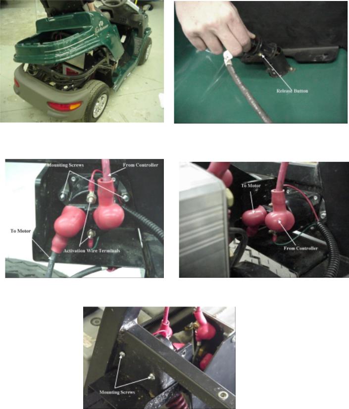
Figure 4-18 |
Figure 4-19 |
|
Figure 4-20 |
Figure 4-21 |
|
Figure 4-22
4-14
 Loading...