


OPERATOR’S MANUAL
SERIES 3000
TRACTOR
Model GT 3100
IMPORTANT: READ SAFETY RULES AND INSTRUCTIONS CAREFULLY
Warning: This unit is equipped with an internal combustion engine and should not be used on or near any unimproved forest-covered, brush-covered or grass-covered land unless the engine’s exhaust system is equipped with a spark arrester meeting applicable local or state laws (if any). If a spark arrester is used, it should be maintained in effective working order by the operator. In the State of California the above is required by law (Section 4442 of the California Public Resources Code). Other states may have similar laws. Federal laws apply on federal lands. A spark arrester for the muffler is available through your nearest engine authorized service dealer or contact the service department, P.O. Box 361131 Cleveland, Ohio 44136-0019.
CUB CADET LLC P.O. BOX 361131 CLEVELAND, OHIO 44136-0019 [www.cubcadet.com]
FORM NO. 769-01495B
(10/06)

TABLE OF CONTENTS
PAGE
TRACTOR PREPARTION . . . . . . . . . . . . . . . . . . . . . . . . . . . . . . . . . . . . . . 3 IMPORTANT SAFE OPERATION PRACTICES . . . . . . . . . . . . . . . . . . . . . 4 CALLING SERVICE INFORMATION . . . . . . . . . . . . . . . . . . . . . . . . . . . . . . 8 FINDING YOUR MODEL & SERIAL NUMBER . . . . . . . . . . . . . . . . . . . . . . 8 SAFETY LABELS FOUND ON YOUR UNIT . . . . . . . . . . . . . . . . . . . . . . . . 9 SLOPE GAUGE . . . . . . . . . . . . . . . . . . . . . . . . . . . . . . . . . . . . . . . . . . . . . 10 CONTROLS AND FEATURES . . . . . . . . . . . . . . . . . . . . . . . . . . . . . . . . . . 11 OPERATION . . . . . . . . . . . . . . . . . . . . . . . . . . . . . . . . . . . . . . . . . . . . . . . . 16 ADJUSTMENTS . . . . . . . . . . . . . . . . . . . . . . . . . . . . . . . . . . . . . . . . . . . . . 21 MAINTENANCE . . . . . . . . . . . . . . . . . . . . . . . . . . . . . . . . . . . . . . . . . . . . . 23 LUBRICATION ILLUSTRATION . . . . . . . . . . . . . . . . . . . . . . . . . . . . . . . . . 24 ENGINE INFORMATION . . . . . . . . . . . . . . . . . . . . . . . . . . . . . . . . . . . . . . 31 TROUBLE SHOOTING . . . . . . . . . . . . . . . . . . . . . . . . . . . . . . . . . . . . . . . . 37 OPTIONAL EQUIPMENT . . . . . . . . . . . . . . . . . . . . . . . . . . . . . . . . . . . . . . 38 SPECIFICATIONS . . . . . . . . . . . . . . . . . . . . . . . . . . . . . . . . . . . . . . . . . . . 39 LIMITED WARRANTY STATEMENTS . . . . . . . . . . . . . . . . . . . . . . . . . . . . 40 QUICK REFERENCE PARTS . . . . . . . . . . . . . . . . . . . . . . . . . . . . . . . . . . 44
2

SECTION 1: TRACTOR PREPARATION
Connect the Battery
Battery posts, terminals and related accessories contain lead and lead compounds. Wash hands after handling.
The tractor is shipped with a sealed battery, with the positive battery cable factory connected. The negative cable must be connected.
Note: Make sure the ignition switch is in the "OFF" position before attaching the battery cable.
•Open the tractor hood. Remove the upper bulkhead baffle from the front of the dash panel by lifting upward on the locking tab on each side of the baffle.
•Remove the protective cap from the negative terminal of the battery.
•Connect the black battery cable to the negative battery post. Slide terminal cover over the connection and reinstall the upper baffle.
Position the High Back Seat
For shipping purposes the seat is installed sideways. Reposition the seat as follows:
•Remove from the seat the two screws NOT fastening the seat to the hinge brackets.
•Loosen the RH screw and remove the LH screw from the seat and hinge bracket.
•Rotate the rear of the seat to the right and align the four front seat holes with matching holes in the LH and RH hinge brackets.
•Temporarily install the three previously removed screws into the three open front seat holes.
•See Section 8: Adjustments for final seat adjustment procedures.
Hinge Brackets
Rotate
Remove Screw |
Loosen Screw |
Deck Front Lift Rod Assembly
For shipping purposes, the deck front lift rod assembly has been installed on the tractor. Cut the tie strap holding the lift rod assembly to the tractor; then pull downward on the quick latch rod at the front of the tractor to remove the lift rod assembly.
Quick Latch Rod
Lift Rod Assembly
3

SECTION 2: IMPORTANT SAFE OPERATION PRACTICES
WARNING: THIS SYMBOL POINTS OUT IMPORTANT SAFETY INSTRUCTIONS WHICH, IF NOT FOLLOWED, COULD ENDANGER THE PERSONAL SAFETY AND/OR PROPERTY OF YOURSELF AND OTHERS.READ AND FOLLOW ALL INSTRUCTIONS IN THIS MANUAL BEFORE ATTEMPTING TO OPERATE YOUR UNIT. FAILURE TO COMPLY WITH THESE INSTRUCTIONS MAY RESULT IN PERSONAL INJURY. WHEN YOU SEE THIS SYMBOL, HEED ITS WARNING.
WARNING: The engine exhaust, some of its constituents, and certain vehicle components contain or emit chemicals known to the State of California to cause cancer, birth defects or other reproductive harm.
DANGER: Your lawn mower was built to be operated according to the rules for safe operation in this manual. As with any type of power equipment, carelessness or error on the part of the operator can result in serious injury. This lawn mower is capable of amputating hands and feet and throwing objects. Failure to observe the following safety instructions could result in serious injury or death.
1. GENERAL OPERATION
•Read, understand, and follow all instructions in the operator’s manual and on the machine before starting. Keep this manual in a safe place for future and regular reference and for ordering replacement parts.
•Only allow responsible individuals familiar with the instructions to operate the machine. Know controls and how to stop the machine quickly.
•Do not put hands or feet under cutting deck or near rotating parts.
•Clear the area of objects such as rocks, toys, wire, etc., which could be picked up and thrown by the blade. A small object may have been overlooked and could be accidentally thrown by the mower in any direction and cause injury to you or a bystander. To help avoid a thrown objects injury, keep children, bystanders and helpers at least 75 feet from the mower while it is in
operation. Always wear safety glasses or safety goggles during operation or while performing an adjustment or repair, to protect eyes from foreign objects. Stop the blade(s) when crossing gravel drives, walks or roads.
•Be sure the area is clear of other people before mowing. Stop machine if anyone enters the area.
•Never carry passengers.
•Disengage blade(s) before shifting into reverse and backing up. Always look down and behind before and while backing.
•Be aware of the mower and attachment discharge direction and do not point it at anyone. Do not operate the mower without either the entire grass catcher or the chute guard in place.
•Slow down before turning. Operate the machine smoothly. Avoid erratic operation and excessive speed.
4
•Never leave a running machine unattended. Always turn off blade(s), place transmission in neutral, set park brake, stop engine and remove key before dismounting.
•Turn off blade(s) when not mowing.
•Stop engine and wait until blade(s) comes to a complete stop before (a) removing grass catcher or unclogging chute, or (b) making any repairs, adjusting or removing any grass or debris.
•Mow only in daylight or good artificial light.
•Do not operate the machine while under the influence of alcohol or drugs.
•Watch for traffic when operating near or crossing roadways.
•Use extra care when loading or unloading the machine into a trailer or truck. This unit should not be driven up or down a ramp onto a trailer or truck under power, because the unit could tip over, causing serious personal injury. The unit must be pushed manually on a ramp to load or unload properly.
•Never make a cutting height adjustment while engine is running if operator must dismount to do so.
•Wear sturdy, rough-soled work shoes and close-fitting slacks and shirts. Do not wear loose fitting clothes or jewelry. They can be caught in moving parts. Never operate a unit in bare feet, sandals, or sneakers.
•Check overhead clearance carefully before driving under power lines, wires, bridges or low hanging tree branches, before entering or leaving buildings, or in any other situation where the operator may be struck or pulled from the unit, which could result in serious injury.
•Disengage all attachment clutches, thoroughly depress the brake pedal, and shift into neutral before attempting to start engine.
•Your mower is designed to cut normal residential grass of a height no more than 10". Do not attempt to mow through unusually tall, dry grass (e.g., pasture) or piles of dry leaves. Debris may build up on the mower deck or contact the engine exhaust presenting a potential fire hazard.
•Use only accessories approved for this machine by the manufacturer. Read, understand and follow all instructions provided with the approved accessory.
2. SLOPE OPERATION
Slopes are a major factor related to loss of control and tip-over accidents which can result in severe injury or death. All slopes require extra caution. If you cannot back up the slope or if you feel uneasy on it, do not mow it. For your safety, use the slope gauge included as part of this manual to measure slopes before operating this unit on a sloped or hilly area. If the slope is greater than 15° as shown on the slope gauge, do not operate this unit on that area or serious injury could result.
DO:
•Mow up and down slopes, not across. Use extreme caution when changing directions on slopes.
•Remove obstacles such as rocks, limbs, etc.
•Watch for holes, ruts or bumps. Uneven terrain could overturn the machine. Tall grass can hide obstacles.
•Use slow speed. Choose a low enough gear so that you will not have to stop or shift while on the slope. Always keep machine in gear when going down slopes to take advantage of engine braking action.
•Keep all movement on the slopes slow and gradual. Do not make sudden changes in speed or direction. Rapid engagement or braking could cause the front of the machine to lift and rapidly flip over backwards which could cause serious injury.
5
•Avoid starting or stopping on a slope. If tires lose traction, disengage the blade(s) and proceed slowly straight down the slope.
•Follow the manufacturers recommendations for wheel weights or counterweights to improve stability.
•Use extra care with grass catchers or other attachments. These can change the stability of the machine.
DO NOT:
•Do not turn on slopes unless necessary; then, turn slowly and gradually downhill, if possible.
•Do not mow near drop-offs, ditches or embankments. The mower could suddenly turn over if a wheel is over the edge of a cliff or ditch, or if an edge caves in.
•Do not mow on wet grass. Reduced traction could cause sliding.
•Do not try to stabilize the machine by putting your foot on the ground.
•Do not use grass catcher on steep slopes.
•Do not tow heavy pull behind attachments on slopes greater than 5 degrees. When going downhill the added weight may cause you to lose control and possibly overturn the tractor
3. CHILDREN
•Tragic accidents can occur if the operator is not alert to the presence of children. Children are often attracted to the machine and the mowing activity. Never assume that children will remain where you last saw them.
•Keep children out of the mowing area and in watchful care of an adult other than the operator.
•Be alert and turn machine off if children enter the area.
•To avoid back-over accidents, always disengage the cutting blades before shifting in reverse. The "Reverse Caution Mode" should not be used when children or others are around.
•Before and when backing, look behind and down for small children.
•Never carry children, even with the blades off. They may fall off and be seriously injured or interfere with the safe machine operation.
•Never allow children under 14 years old to operate the machine. Children 14 years and over should only operate machine under close parental supervision and proper instruction.
•Use extra care when approaching blind corners, shrubs, trees or other objects that may obscure your vision of a child or other hazard.
•Keep children away from hot or running engines. They can suffer burns from a hot muffler.
•Remove key when machine is unattended to prevent unauthorized operation.
4. SERVICE
•Use extreme care in handling gasoline and other fuels. They are extremely flammable and the vapors are explosive.
•Use only an approved container.
•Never remove fuel cap or add fuel with the engine running. Allow engine to cool at least two minutes before refueling.
•Replace fuel cap securely and wipe off any spilled fuel before starting the engine as it may cause a fire or explosion.
•Extinguish all cigarettes, cigars, pipes and other sources of ignition.
•Never refuel the machine indoors because fuel vapors will accumulate in the area.
•Never store the fuel container or machine inside where there is an open flame or spark, such as a gas hot water heater, space heater or furnace.
•Never run a machine inside a closed area.
6

• To |
reduce fire hazard, |
keep |
the |
• |
Check |
brake |
operation frequently. |
|||||||||||
|
machine free of grass, leaves or |
|
Adjust and service as required. |
|
||||||||||||||
|
other debris build-up. Clean up oil or |
• |
Muffler, |
engine |
and |
belt |
guards |
|||||||||||
|
fuel spillage. Allow machine to cool |
|||||||||||||||||
|
|
become |
hot |
during |
operation and |
|||||||||||||
|
at least 5 minutes before storing. |
|
||||||||||||||||
|
|
can cause a burn. Allow to cool |
||||||||||||||||
• |
Before |
cleaning, |
repairing |
or |
|
|||||||||||||
|
down before touching. |
|
|
|
||||||||||||||
|
inspecting, make certain the blade |
• |
Do not change the engine governor |
|||||||||||||||
|
and all moving parts have stopped. |
|||||||||||||||||
|
Disconnect the spark plug wire, and |
|
settings or overspeed the engine. |
|||||||||||||||
|
keep the wire away from the spark |
|
Excessive |
engine |
|
speeds |
are |
|||||||||||
|
plug to prevent accidental starting. |
|
dangerous. |
|
|
|
|
|
|
|
||||||||
• Check the blade and engine • |
Observe proper disposal laws and |
|||||||||||||||||
|
mounting bolts at frequent intervals |
|
regulations. |
Improper |
disposal of |
|||||||||||||
|
for proper tightness. Also, visually |
|
fluids and materials can harm the |
|||||||||||||||
|
inspect blade for damage (e.g., |
|
environment and the ecology. |
|
||||||||||||||
|
excessive |
wear, |
bent, |
cracked). |
• Prior to disposal, determine the |
|||||||||||||
|
Replace |
with blade which meets |
||||||||||||||||
|
|
proper method to dispose of waste |
||||||||||||||||
|
original equipment specifications. |
|
||||||||||||||||
|
|
from |
your |
|
local |
Environmental |
||||||||||||
• |
Keep all nuts, bolts and screws tight |
|
|
|||||||||||||||
|
Protection |
|
Agency. |
Recycling |
||||||||||||||
|
to be sure the equipment is in safe |
|
centers are established to properly |
|||||||||||||||
|
working condition. |
|
|
|
|
dispose of materials in an |
||||||||||||
• Never tamper with safety devices. |
|
environmentally safe fashion. |
|
|||||||||||||||
|
|
|
|
|
|
|
|
|
|
|
||||||||
|
Check their proper operation • |
Use |
proper |
|
containers |
|
when |
|||||||||||
|
regularly. Use all guards as |
|
draining fluids. Do not use food or |
|||||||||||||||
|
instructed in this manual. |
|
|
|
beverage |
containers |
that |
may |
||||||||||
• |
After striking |
a foreign object, |
stop |
|
mislead someone into drinking from |
|||||||||||||
|
them. |
|
Properly |
dispose |
of |
the |
||||||||||||
|
the |
engine, |
remove the |
wire |
from |
|
|
|||||||||||
|
|
containers immediately following the |
||||||||||||||||
|
the |
spark |
plug |
and |
thoroughly |
|
||||||||||||
|
|
draining of fluids. |
|
|
|
|
|
|||||||||||
|
inspect the mower for any damage. |
|
|
|
|
|
|
|||||||||||
|
• |
DO NOT pour oil or other fluids into |
||||||||||||||||
|
Repair the damage before restarting |
|||||||||||||||||
|
and operating the mower. |
|
|
|
the ground, down a drain or into a |
|||||||||||||
• Grass catcher components are |
|
stream, pond, lake or other body of |
||||||||||||||||
|
water. |
|
Observe |
Environmental |
||||||||||||||
|
subject to wear, damage and |
|
Protection Agency regulations when |
|||||||||||||||
|
deterioration, |
which could expose |
|
disposing of oil, fuel, coolant, brake |
||||||||||||||
|
moving parts or allow objects to be |
|
fluid, filters, batteries, tires and other |
|||||||||||||||
|
thrown. For your safety protection, |
|
harmful waste. |
|
|
|
|
|
||||||||||
|
frequently |
check components |
and |
• With the exception of utilizing the |
||||||||||||||
|
replace |
with |
manufacturer’s |
|||||||||||||||
|
|
deck wash |
feature |
on the |
mower |
|||||||||||||
|
recommended |
parts |
when |
|
||||||||||||||
|
|
decks, we do not recommend the |
||||||||||||||||
|
necessary. |
|
|
|
|
|
||||||||||||
|
|
|
|
|
|
use of a pressure washer or garden |
||||||||||||
|
|
|
|
|
|
|
|
|
||||||||||
• Mower blades are sharp and can |
|
hose to clean your tractor. Water |
||||||||||||||||
|
cut. Wrap the blade(s) or wear |
|
may cause damage to electrical |
|||||||||||||||
|
gloves and use extra caution when |
|
components; |
pulleys; |
bearings; or |
|||||||||||||
|
servicing blade(s). |
|
|
|
|
the engine. |
|
|
|
|
|
|
|
|||||
WARNING - YOUR RESPONSIBILITY: Restrict the use of this power machine to persons who read, understand and follow the warnings and instructions in this manual and on the machine.
7

SECTION 3: CALLING SERVICE INFORMATION
The engine manufacturer is responsible for all engine-related issues with regards to performance, power-rating, and specifications.
If you have difficulties with the unit, have any question regarding the operation or maintenance of this equipment, or desire additional information not found in this manual, contact your dealer. If you need help locating a dealer in your area, contact the Customer Dealer Referral Line by calling:
1-877-282-8684
Or you may contact Cub Cadet via the internet by logging on to our Wed Site at:
www.cubcadet.com
Before calling your local dealer, make sure that you have your model and serial numbers ready.
SECTION 4: FINDING YOUR MODEL & SERIAL NUMBER
This Operator’s Manual is an important part of your new tractor. It will help you prepare, maintain and safely operate your tractor. Please read and understand what it says.
Before you prepare your tractor for its first use, please locate the tractor and engine model plates and copy the information from them into the spaces provided below. The information on the model plates is very important if you need help from your dealer or the Cub Cadet customer support department. Refer to Figure 1.
•The tractor model plate is located on the right frame rail behind the right front tire.
•The engine identification numbers appear on a decal (or decals) affixed to the engine shrouding.
XXXXXXXXXXX |
XXXXXXXXXX |
Model Number |
Mfg. Date |
|
CUB CADET LLC |
|
P. O. BOX 361131 |
www.cubcadet.com |
CLEVELAND, OH 44136 |
DEALER LOCATOR PHONE NUMBER: 877-282-8684
Figure 1
Model Number |
|
Mfg. Date (Serial No.) |
||
|
|
|
|
|
Engine Model No. |
|
Engine Spec. No. |
|
Engine Serial No. |
8
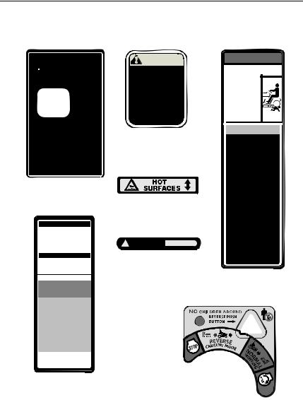
SECTION 5: SAFETY LABELS FOUND ON YOUR UNIT
DECK HEIGHT
ADJUSTMENT
(360 Turn Equals 1/2" Adjustment)
1.RAISE DECK LIFT LEVER UNTIL THE NUMBER 6 APPEARS IN WINDOW.
POSITION INDICATOR
2.TURN KNOB COUNTER CLOCKWISE TO LOWER DECKSTOP.
3.TURN KNOB CLOCKWISE TO RAISE DECKSTOP.
4.LOWER DECK LIFT LEVER UNTIL POSITION INDICATOR STOPS.
5.REPEAT PROCESS IF NECESSARY.
WARNING |
TO ENSURE SAFE AND |
PROPER OPERATION |
OF TRANSMISSION, |
ONLY USE CUB CADET |
DRIVE SYSTEM |
FLUID PLUS. |
737-3120 - 1 QUART |
737-3121 - 1 GALLON |
READ OPERATOR'S |
MANUAL |
Rear Drawbar
Running Board - Left
STARTING INSTRUCTIONS
1.BE FAMILIAR WITH CONTROLS BEFORE STARTING ENGINE AND OPERATING.
2.SET CHOKE, MOVE THROTTLE TO MID POSITION AND DEPRESS BRAKE PEDAL.
3.TURN KEY TO THE START POSITION.
4.AFTER ENGINE STARTS OPEN CHOKE.
STOPPING INSTRUCTIONS
1.DISENGAGE PTO AND SET PARKING BRAKE.
2.MOVE THROTTLE CONTROL TO MID POSITION AND TURN KEY OFF.
OPERATING MODES
NORMAL MOWING
YOU MUST DISENGAGE BLADES/PTO, (POWER TAKE OFF) BEFORE TRAVELING IN REVERSE.
Hood Hinge Bracket
! WARNING HOT AREAS
Front Grille
 DANGER
ROTATING BLADES CAUSE
SERIOUS INJURY OR DEATH
• DO NOT MOW WHEN |
CHILDREN OF OTHERS |
ARE AROUND. |
• NEVER CARRY |
CHILDREN EVEN |
WITH BLADE(S) OFF. |
• LOOK DOWN AND |
BEHIND BEFORE AND |
WHILE BACKING. |
• MOWING IN REVERSE |
IS NOT RECOMMENDED. |
 WARNING
AVOID SERIOUS INJURY
OR DEATH
•GO UP AND DOWN SLOPES, NOT ACROSS.
•AVOID SUDDEN TURNS.
•DO NOT OPERATE UNIT WHERE IT COULD SLIP OR TIP.
•IF MACHINE STOPS GOING UPHILL, STOP PTO AND BACK DOWN HILL SLOWLY.
•KEEP SAFETY DEVICES [GUARDS, SHIELDS, AND SWITCHES] IN PLACE AND WORKING.
•REMOVE OBJECTS THAT COULD BE THROWN BY THE BLADES.
•KNOW LOCATION AND FUNCTION OF ALL CONTROLS.
•BE SURE THE BLADES AND THE ENGINE ARE STOPPED BEFORE PLACING HANDS OR FEET NEAR BLADES.
•BEFORE LEAVING OPERATOR’S POSITION, DISENGAGE PTO, ENGAGE BRAKE LOCK, SHUT OFF ENGINE AND REMOVE KEY.
READ OPERATOR’S
MANUAL
Running Board - Right
REVERSE
CAUTION MODE
1. TURN KEY TO REVERSE CAUTION
MODE POSITION.
2. DEPRESS REVERSE PUSH BUTTON.
(RED INDICATOR LIGHT “ON”)
WHEN RED LIGHT IS “ON” MACHINE
CAN BE OPERATED IN REVERSE WITH
MOWER BLADES ENGAGED.
IMPORTANT: MOWING IN REVERSE IS
NOT RECOMMENDED.
3. AFTER RESUMING FORWARD OPERATION, RETURN KEY TO “NORMAL MOWING” POSITION.
NOTE: IN BOTH MODES, WHEN OPERATOR
LEAVES SEAT, ENGINE WILL STOP UNLESS
PARKING BRAKE IS SET AND BLADES ARE
DISENGAGED.
Running Board - Center
Key Switch/Module -
Dash Panel
Figure 2
9
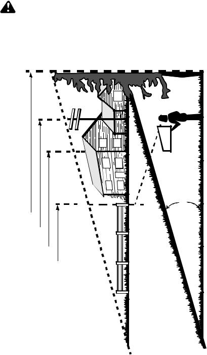
SECTION 6: SLOPE GAUGE
WARNING: Do not mow on inclines with a slope in excess of 15 degrees (a rise of approximately 2-1/2 feet every 10 feet). A riding mower could overturn and cause serious injury. If operating a walkbehind mower on such a slope, it is extremely difficult to maintain your footing and you could slip, resulting in serious injury.
•Operate RIDING mowers up and down slopes, never across the face of slopes.
•Operate WALK-BEHIND mowers across the face of slopes, never up and down slopes.
MAY NOT OPERATE SAFELY. |
|
|
|
|
E |
|
YOU |
|
|
|
|
P |
|
|
|
|
|
S |
|
|
|
|
|
|
|
O |
|
WHERE |
|
|
|
|
L |
|
|
|
|
|
° |
|
|
|
|
|
|
|
5 |
|
|
|
|
|
|
1 |
|
|
|
|
|
|
A |
|
|
|
|
|
|
G |
|
SLOPESDETERMINETOGUIDEAASPAGETHIS |
TREEVERTICALAWITHLEVELTHISHOLD |
POLEPOWERA |
BUILDINGAOFCORNERA |
POSTFENCEAOR |
N |
15° |
I |
||||||
|
|
|
|
|
T |
|
|
|
|
|
|
N |
|
|
|
|
|
|
E |
|
|
|
|
|
|
S |
|
|
|
|
|
|
E |
|
|
|
|
|
|
R |
|
|
|
|
|
|
P |
|
|
|
|
|
|
E |
|
|
|
|
|
|
R |
|
|
|
|
|
|
, |
|
|
|
|
|
|
E |
|
|
|
|
|
|
N |
|
|
|
|
|
|
I |
|
|
|
|
|
|
L |
|
|
|
|
|
|
D |
|
|
|
|
|
|
E |
|
|
|
|
|
|
T |
|
|
|
|
|
|
T |
|
|
|
|
|
|
O |
|
|
|
|
|
|
D |
|
|
|
|
|
|
N |
|
|
|
|
|
|
O |
|
|
|
|
|
|
D |
|
|
|
|
|
|
L |
|
|
|
|
|
|
O |
|
|
|
|
|
|
F |
|
USE |
AND |
|
|
|
|
|
|
SIGHT |
|
|
|
|
|
|
|
|
|
|
10 |
|

SECTION 7: CONTROLS and FEATURES
B
A
C
D
T
S
R
Q
P
O 

N 
M 
IL
E
F
G
H
I
J
(Not Shown)
K
|
Figure 3 |
|
|
A |
Low Fuel Indicator Lamp |
K |
Transmission Release Rod |
B |
Indicator Panel/Hour Meter |
L |
Transmission Oil Fill/Dipstick |
C |
Key Switch Module |
M |
Fuel Fill Cap |
D |
Parking Brake Lever |
N |
Cup Holder |
E |
PTO Switch |
O |
Hydraulic Lift Lever |
F |
Brake Pedal |
P |
Center Height Position Indicator |
G |
Reverse Pedal |
Q |
Deck Height Adjustment Knob |
H |
Forward Pedal |
R |
Cruise Control Lever |
I |
12V Power Outlet |
S |
Throttle Lever |
J |
Seat Adjustment Lever (Not Shown) |
T |
Choke Lever |
* Steering Wheel and Seat Removed For Clarity
11
NOTE: References to LEFT and RIGHT indicate that side of the tractor when facing forward while seated in the drivers seat. Reference to FRONT indicates the grille end of the tractor; to REAR, the drawbar end.
Steering Wheel
The steering wheel, centered on the dash panel, is used to turn the tractor left or right while driving.
NOTE: This tractor is equipped with hydraulic power steering. With this feature, the center of the steering wheel may not stay center aligned.
A. Low Fuel Indicator Lamp
The Low Fuel indicator lamp is on the dash panel. This indicator will illuminate when the tractor is low on fuel.
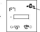
B. Indicator Panel/Hour Meter
The indicator panel/hour meter uses indicator lights to display the status of various functions of the tractor and also records the accumulated hours of operation. The Indicator Panel Features are as follows. Refer to Figure 4.
Oil Pressure Indicator
•This warning lamp indicates low engine oil pressure. If this indicator illuminates, stop the tractor immediately and check the engine oil level. If the oil level is within the operating range, but the light remains on, contact your Cub Cadet dealer.
NOTE: The oil pressure indicator may illuminate when the key switch is turned to an on position, but should turn off when the engine is started.
PTO Engaged Indicator
•This indicator illuminates when the key switch is turned to the "Start" position while the PTO switch is pulled outward in the "Engaged" position. Check this indicator if the engine will not crank with the key switch in the "Start" position. If necessary, move the PTO switch to the "Disengaged" position.
Brake Engaged Indicator
•This indicator illuminates when the key switch is turned to the "Start" position and the brake pedal is not fully depressed. Check this indicator if the engine will not crank with the key switch in the "Start" position. If necessary, fully depress the brake pedal.
Brake Engaged Indicator
•This indicator illuminates when the key switch is turned to the "Start" position and the brake pedal is not fully depressed. Check this indicator if the engine will not crank with the key switch in the "Start" position. If necessary, fully depress the brake pedal.
LCD Hour Meter Display
The hour meter shows the hours (tenths of an hour-right most digit) that the tractor has been operated.
The hour meter display is activated when the key switch is turned to either the “Normal Mowing” or the “Reverse Caution Mode” switch positions. When the key switch is turned to an on position, the battery indicator light briefly illuminates and the battery voltage is briefly displayed. The display then changes to the accumulated hours.
Battery
Indicator

Hour
Meter
PTO
Engaged


Indicator
Oil
 Pressure
Indicator
Parking Brake


 Engaged
Indicator
Figure 4
12
NOTE: A record of the actual hours of operation should be kept to assure maintenance procedures are completed according to the schedule in this manual.
The Indicator Monitor will also remind the operator of maintenance intervals for changing the engine oil. The LCD will alternately flash the recorded hours, “CHG” and “OIL” for five minutes, after every 50 hours of recorded operation elapse. The maintenance interval lasts for two hours (from 5052, 100-102, 150-152, etc.). The LCD will flash as described for five minutes every time the tractor’s engine is started during this maintenance interval. Follow the oil change intervals provided in the Maintenance section of this Manual.
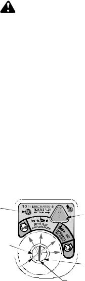
C. Key Switch Module
The key switch module consist of a four position key switch, the “Reverse Push Button”, and a red indicator light. Refer to Figure 5.
The four key positions of key switch module (Refer to Figure 5) and their functions are as follows:
•Stop — Stops the tractor engine and shuts down the tractor’s electrical circuits.
•Reverse Caution Mode — This position allows the machine to be operated in reverse with the blades (PTO) engaged.
•Normal Mowing — The normal operating position. All safety inter-
lock circuits are activated and the blades (PTO) will disengage when the tractor is driven in the reverse direction.
•Start — Energizes the starter motor to crank and start the tractor engine. Release the key as soon as the engine starts and the key will return to “NORMAL MOWING” position.
To prevent accidental starting, remove the key from the key switch when the tractor is not in use.
Reverse Push Button — The orange/ triangular button at the top/right corner of the key switch module activates the system which allows the tractor’s blades (PTO) to remain engaged when the tractor is driven in the reverse direction. The key must be turned to the “REVERSE CAUTION MODE” and the operator must be in the tractor seat prior to depressing the button to activate the system.
The Red Indicator Light at the top/left corner of the key switch module comes “ON” to alert the operator that the key has been turned to the “Reverse Caution Mode” position, the “Reverse Push Button” has been depressed, and that the blades will remain engaged when the machine is driven in reverse.
IMPORTANT: Mowing in reverse is not recommended.
Indicator Light |
|
|
|
|
|
|
|
Reverse Push |
|
|
|
|
|
|
|||||
|
|
|
|
|
|
|
|
|
|
|
|
|
|
|
|
|
|
|
Button |
Key in Start |
|
|
|
|
|
|
|
|
|
|
|
|
|
|
|
|
|
||
|
|
|
|
|
|
|
|
||
|
|
|
|
|
|
|
|||
Position |
|
|
|
|
|
|
|
||
|
|
|
|
|
|
|
|
|
Key in Stop |
Key in Normal |
|
|
|
||||||
|
Position |
||||||||
Mowing Mode
Key in Reverse
Caution Mode
Figure 5
13

D. Parking Brake Lever
Figure 6
The parking brake lever is located to the right of the steering wheel in the dash panel. With the brake pedal depressed fully, push the parking brake lever downward and release the brake pedal to lock the parking brake.
E. PTO Switch
The PTO switch is located on the lower/right side the dash panel. Pull the knob outward to engage the PTO clutch. Push the knob inward to disengage the PTO clutch.
F. Brake Pedal
Figure 7
The brake pedal is located at the front of the right running board above the forward and reverse pedals. Depress to stop the tractor and disengage the cruise control. Fully depress the brake pedal to activate the safety interlock switch when starting the tractor.
G. Reverse Pedal
Figure 8
WARNING: Always look down and behind before and while backing. Do not operate the tractor when children or others are around. Stop the tractor immediately if someone enters the area.
The reverse control pedal is located on the right running board below the brake pedal. Press the pedal down to move in reverse.
H. Forward Pedal
Figure 9
The forward control pedal is located on the right running board below the brake pedal. Slowly press down on the pedal to start moving forward. The forward ground speed of the tractor is directly affected by the distance the pedal is depressed.
I.12V Power Outlet
The 12V power outlet is located on the front/right surface of the fender, below the seat. It is used for the convenience of plugging in accessories that require a power source with a maximum load of 5 amps at 12 volts.
J. Seat Adjustment Lever
The seat adjustment lever is located below the seat. This lever is used to adjust the seat forward or backward.
K. Transmission Release Rod
The transmission release rod is located at the back of the tractor in the draw bar. This rod, when engaged, allows the tractor to be pushed short distances by hand.
To disengage the transmission, pull back on the rod until its locking flange is visible outside the drawbar, then lower the rod into the slot and release. To reengage the transmission, pull back on the rod, lift out of the slot and release.
14
 Loading...