


SERIES 3000
SERVICE MANUAL
770-10227
Series 3000 Technical Handbook |
|
Table of Contents |
|
|
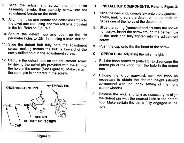
Section |
Pre-Delivery Check List and Service Specifications 1999 ................................................................................ |
1 |
Engineering Updates 1999................................................................................................................................ |
2 |
Fender Removal and Reinstallation .................................................................................................................. |
3 |
Hydraulic Step by Step Flow Charts ................................................................................................................. |
4 |
Power Steering Cylinder Removal and Replacement ....................................................................................... |
5 |
Power Steering Pump Disassemble, Inspect and Reassemble ........................................................................ |
6 |
Center Lift Cylinder Removal and Replacement ............................................................................................... |
7 |
Pump Adapter Removal and Replacement ....................................................................................................... |
8 |
BDU-21L-500 Pressure Test Procedure ........................................................................................................... |
9 |
Hydraulic Steering Pump Removal and Replacement .................................................................................... |
10 |
Hydraulic Valve Removal and Replacement ................................................................................................... |
11 |
Engine Removal and Replacement................................................................................................................. |
12 |
Transmission Removal and Installation .......................................................................................................... |
13 |
Transmission Inspection and Disassembly ..................................................................................................... |
14 |
Transmission Reassembly .............................................................................................................................. |
15 |
Neutral Control Adjustment ............................................................................................................................. |
16 |
3000 Series Electrical ..................................................................................................................................... |
17 |
BDU-21L Transmission ................................................................................................................................... |
18 |

PreDelivery Check List
1000, 1500, 2000, 2500, 3000 Series
CUSTOMER NAME_____________________________ |
MODEL NUMBER______________________________ |
ADDRESS____________________________________ |
SERIAL NUMBER______________________________ |
CITY_________________________________________ |
ATTACHMENT MODEL NUMBER_________________ |
STATE________________________ZIP____________ |
ATTACHMENT SERIAL NUMBER_________________ |
HOME PHONE NUMBER________________________ |
|
|
|
ENGINE INFORMATION: |
TRANSMISSION INFORMATION: |
ENGINE MAKE__________________________________ |
TRANSMISSION MAKE______________________________ |
ENGINE MODEL NUMBER_________________________ |
TRANSMISSION MODEL NUMBER_____________________ |
ENGINE SPEC. NUMBER__________________________ |
TRANSMISSION SERIAL NUMBER_____________________ |
ENGINE SERIAL NUMBER_________________________ |
|
CHECK-ADJUST AS REQUIRED. Inspection time for these checks are not reimbursable as warranty. Repairs that are determined to be necessary due to defects in material or workmanship are reimbursable under warranty.
Manuals Complete: (Use Operator Manual and related manuals during checks).
Owners Manual.
Engine Manual (If Applicable). Attachment Manual (If Applicable).
Battery & Connections:
Check battery for specific gravity (1.265). Charge battery at 4 amps max. to 1.265 specific gravity if needed.
Tires & Wheels:
Check & adjust pressure in tires as specified in Operator’s Manual.
Tighten lug nuts / bolts as specified in Operator’s Manual.
Check Lights & Indicators:
Check headlights / taillights (If Applicable). Check all dash lights (If Applicable).
Check hour meter / service minder (If Applicable).
Lubrication:
Check engine oil level.
Check transmission oil level.
Air Cleaner & Connections:
Remove air cleaner cover to verify air filter & pre cleaner is installed.
Insure retaining bolt seal is installed. Insure proper installation of breather hose. Check operation of throttle & choke cables.
Steering:
Check for 1/16 to 5/16 inch toe in. (Refer to Operator’s Manual).
Insure equal travel right & left.
Hydrostatic / Gear Drive:
Check brakes.
Check for neutral when brake pedal is depressed. Check for neutral when forward & reverse pedal is released.
Grease Pivot Points:
Front axle pivot bar & steering housing. Each steering knuckle.
Each front wheel.
All grease points on mower deck. (Refer to Operator’s Manual).
PTO / Attachments:
Check PTO air gap (.014-.017) (If Applicable). Follow burnishing procedures. (listed on back). Level deck. (Refer to Operator’s Manual).
Adjust lift assist spring (If Applicable). Inspect linkage.
Brake Function:
Verify proper brake performance & parking brake. Refer to Operator’s Manual or Service Manual to adjust brakes.
Operation:
Verify proper operation of diff. lock (If Applicable) & transmission.
Check operation of no cut in reverse feature. Check all safety features of shutdown.
Check Engine Speeds:
Low idle - 1700 RPM. High idle - 3600 RPM.
(Refer to Operator’s Manual or Engine Service Manual for adjustment procedures).
Continued On Back

Final Inspection: |
ADDITIONAL ATTACHMENTS: |
Check fuel system for leaks. Tank, lines, fittings etc. |
ATTACHMENT MODEL NUMBER_________________ |
Check for missing or loose fasteners & decals. |
ATTACHMENT SERIAL NUMBER_________________ |
Clean / polish. Check overall appearance. |
|
Place manuals in a appropriate location (Under Seat) |
ATTACHMENT MODEL NUMBER_________________ |
at conclusion. |
ATTACHMENT SERIAL NUMBER_________________ |
|
ATTACHMENT MODEL NUMBER_________________ |
|
ATTACHMENT SERIAL NUMBER_________________ |
|
ATTACHMENT MODEL NUMBER_________________ |
|
ATTACHMENT SERIAL NUMBER_________________ |
|
|
P.T.O. CLUTCH BURNISHING PROCEDURE:
Start unit.
Place throttle lever in the 1/2 throttle position.
Cycle P.T.O. clutch 10 times. (10 seconds on / 10 seconds off).
Place throttle lever in the full throttle position.
Cycle P.T.O. clutch 10 times. (10 seconds on / 10 seconds off).
NOTES:
Customer Signature____________________________________________________________Date______________
Service Technician Signature_____________________________________________________Date_____________

1999 Specifications
Cub Cadet 1999 Specifications
SERIES 3000 TRACTORS
Features and General Specifications: |
|
|
|
|
|
|||
• Hydrostatic Drive w/Cruise Control |
|
|
• |
Cast Iron Front Axle |
||||
• |
Shaft Drive Transmission |
|
|
• |
4.5 Gallon Fuel Tank |
|||
• Shaft Drive Deck and Front Attachments |
• |
E-Vac PTO System |
||||||
• |
Power Steering |
|
|
|
• |
Tilt Steering Wheel |
||
• |
Hydraulic Lift |
|
|
|
• |
Differential Lock (3205, 3225) |
||
• Welded Full Length Twin Channel, 9 gauge |
• |
Speed: |
|
|||||
|
Steel Frame |
|
|
|
|
– 0-7 MPH Forward |
||
• |
Deck Height Indicator |
|
|
|
– 0-4 MPH Reverse |
|||
• |
Halogen Headlights |
|
|
• |
Tires: |
|
||
• |
Taillights w/Reverse Lights |
|
|
|
– 16" x 7.5" |
Front |
||
• |
27" Turning Radius |
|
|
|
– 24" x 10.5" |
Rear |
||
|
|
|
|
|
|
|
|
|
|
Model |
|
Factory No. |
|
|
|
Series 3000 |
|
|
3165 |
|
14A-654-100 |
16.0 |
HP B&S Twin Vanguard OHV, Hydro, Power Steering, Power Lift |
|||
|
3185* |
|
14A-665-100 |
18.0 |
HP B&S Twin Vanguard, Hydro, Power Steering, Power LIft |
|||
|
3186 |
|
14A-668-100 |
18.0 |
HP Kohler V-Twin OHV, Hydro, Power Steering, Power Lift |
|||
|
3205 |
|
14A-685-100 |
20.0 |
HP Liquid Cooled V-Twin Kawasaki OHV, Power Steering, Power Lift, |
|||
|
|
|
|
Differential Lock |
|
|
|
|
|
3225 |
|
14A-688-100 |
22.0 |
HP V-Twin Kohler OHV, Power Steering, Power Lift, Differential Lock |
|||
|
|
|||||||
|
*Limited Quantities Available |
|
|
|
|
|
||
|
Model |
Factory No. |
|
|
Attachments and Accessories |
|||
|
345 |
|
190-345-100 |
Fan Assist Bagger for 48"/54" Deck |
|
|||
289190-289-100 48" Deck, Shaft Driven
290190-290-100 54" Deck, Shaft Driven
291190-291-100 60" Deck, Shaft Driven (3205 & 3225 only)
343 |
190-343-100 |
Hydraulic Front Hitch System |
352190-352-100 54" Front Mounted Snow Blade (Requires 343; Optional 288 or 171)
353190-353-100 45" Snow Thrower, Shaft Driven (Req. 343)
299 |
190-299-100 |
Ag Tires/Rims 23" x 8.5" |
|
249 |
190-249-100 |
Ag Tires/Rims 23" x 10.5" |
|
366 |
190-366-100 |
Rear Turf Tires/Rims 24" x 10.5" |
|
365 |
190-365-100 |
Hydraulic 3 Pt. Hitch, Category “O” |
|
924 |
190-924-100 |
‘A’ Frame Hitch Adapter, Converts Sleeve Hitch Attachments To Cat. “O” |
|
|
|
3-Pt. Hitch |
|
163 |
190-163-100 |
42"' Lawn Sweeper |
|
653 |
190-653-100 |
10 |
Cu. Ft. Cart |
368 |
190-368-100 |
10 |
Cu. Ft. Heavy Duty Dump Cart |
425 |
190-425-100 |
17 |
Cu. Ft. Heavy Duty Dump Cart |
161 |
190-161-000 |
48" Poly Bed Liner (Fits All 10’s) |
|
|
|
(Tailgate Section Must Be Cut Out By Dealer) |
|
1 - 2
|
|
1999 Specifications |
|
Cub Cadet 1999 Specifications (continued) |
|
|
|
|
Model |
Factory No. |
Attachments and Accessories |
162 |
190-162-000 |
60" Poly Bed Liner (Fits All 17’s) |
|
|
(Tailgate Section Must Be Cut Out By Dealer |
288 |
190-288-100 |
Hydraulic Front Angle Kit (Cannot Be Used w/353) |
171 |
190-171-100 |
Manual Angle Kit (Cannot Be Used w/353) |
412 |
190-412-100 |
Rear Wheel Weights (2 per Set) @ 75# |
413 |
190-413-100 |
Front & Rear Wt. Bracket (Supports 390 Wt.) |
190390 |
190-390-100 |
Suitcase Weights |
506 |
590-605-100 |
Mulcher, 48" Deck+ |
507 |
590-507-100 |
Mulcher, 54" Deck++ |
920 |
190-920-000 |
12" Mold Board Plow (Requires 365) |
921 |
190-921-000 |
Tandem Disc (Requires 365) |
922 |
190-922-000 |
Spring Cultivator (Requires 365) |
400 |
190-400-100 |
38" Tiller, 8.0 HP B&S Engine (Requires 365) |
206 |
190-206-100 |
Series 3000 Tractor Display Stand |
|
|
|
NOTES:
+To Mount on Series 3000 Deck You Must Order Qty. 1 - 603-0624 and 1- 603-0625 From Parts
++To Mount on Series 3000 Deck You Must Order Qty. 1- 603-0626 and 1- 603-0627 From Parts It is recommended that the 3165 be equipped with a 48" deck for maximum performance.
1 - 3

NOTES
Cub Cadet 3000
1999 3000 Series Engineering Updates
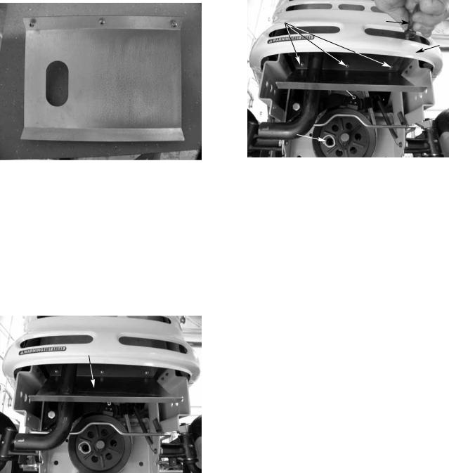
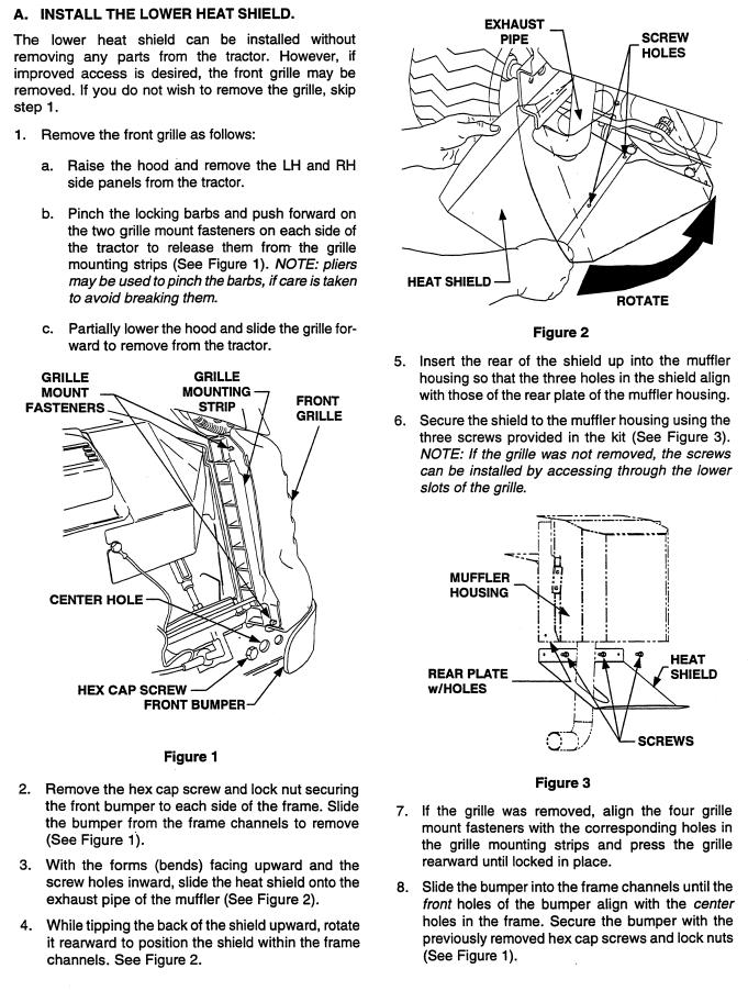
HEAT SHIELD
A heat shield has been installed on all 3000 series tractors for 1999. The heat shield prevents the exhaust gases from browning the grass. Use kit #7593927. See Service Advisory CC-371.
Heat Shield
1.Remove both of the hex bolts and lock nuts securing the front bumper to the frame using a 3/4" socket and a 3/4" wrench.
2.Remove the bumper.
3.Slide the muffler shield over the exhaust pipe and rotate it into position.
NOTE: Align all three holes in the top of the muffler shield with the existing shield. Also, the muffler shield will be slanting towards the bottom of the front grill assembly.
Heat Shield
4.Secure the muffler shield with three sheet metal screws.
NOTE: Use a long flat blade screwdriver through the air holes in the grill to tighten the sheet metal screws securely.
Sheet Metal Screws |
Screwdriver |
Grill
Mark used in Production to Test PTO Activation
5. Install the bumper.
LIFT LINK
The lift link has been modified by strengthening the powder metal that connects the lift lever to the hydraulic valve for 1999.
CHECK VALVE
For 1999, a check valve will be installed to the hydraulic valve to prevent the decks and other attachments from leaking down during and after usage.
LIFT STOP BRACKET
A lift stop bracket will be installed on the left hand side of the deck to prevent the deck from hanging up during operations. Use kit #759-3927.
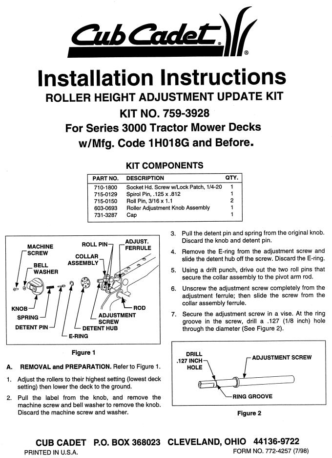
ROLLER HEIGHT ADJUSTER
The rear roller height adjustment mechanism will be changed for 1999. A newly designed detent pin will replace the old one, preventing the loss of cutting height during operations. Use kit #759-3928.
FRONT DECK HANGER ASSEMBLY
The front roller bracket has been redesigned to prevent the front lift rod from detaching during operation.
SEAT IMPROVEMENTS
A safer seat spring, part number 732-0869, can be installed to level the seat for petite operators. In addition, the seat part number 757-3010A, is now made out of a softer material for better operator comfort. See Service Advisory CC-358A Sections 5 and 6.
FRONT MOWER DECK HEIGHT ADJUSTER
The front mower deck height adjuster pins have been changed from ball detent pins to quick pull pins.
2 - 1
Cub Cadet 3000
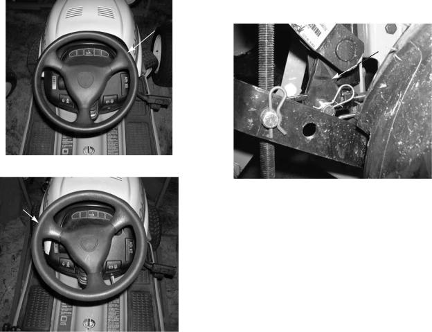
STEERING WHEEL
The thickness of the steering wheel has been increased for operator comfort.
Steering
Wheel
Thinner
Old Style Steering Wheel
Steering
Wheel
Thicker
New Thicker Steering Wheel
ROCK SHAFT ASSEMBLY FOR 3 POINT HITCH 190-365-100
The cylinder arms have been redesigned with two V sections cut out to allow for clearance of the clevis nut on the cylinder shaft. See Service Advisory CC-364.
Grooved
Out Area
3000 Series Lift Assembly
2 - 2
Cub Cadet 3000
2 - 3
Cub Cadet 3000
2 - 4

Cub Cadet 3000
2 - 5
Cub Cadet 3000
2 - 6
Cub Cadet 3000
2 - 7

NOTES
Cub Cadet 3000
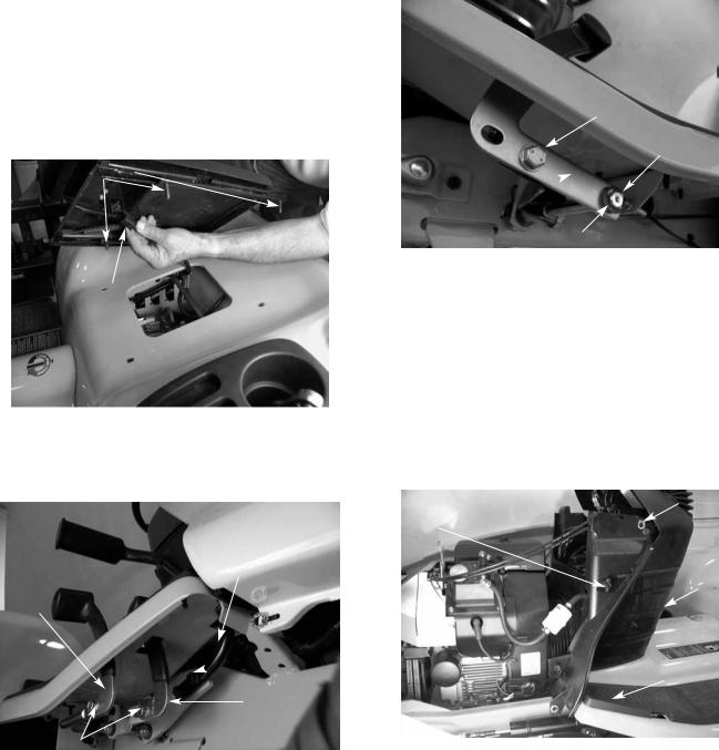
Fender Assembly Removal and Reinstallation
1.Slide the seat back and remove the front two pan torx head screws using a T30 torx.
2.Slide the seat forward and remove the rear two pan torx head screws using a T30 torx.
3.Pivot the seat assembly to the side and disconnect the seat safety switch. See figure 1.
NOTE: Be careful not to scratch the fender with the seat support brackets. It is advisable to use a towel or cloth under the seat when pivoting the seat.
4.Remove the seat from the tractor. See figure 1.
Torx Screws
Seat Safety
Switch
FIGURE 1.
5.Remove all the hex bolts securing the three foot pedals to the right side of the unit using a 9/16 socket. See figure 2.
Brake
Pedal
Reverse
Pedal
Hex
 Bolts
Bolts
Forward
Pedal
Hex Bolts
FIGURE 2.
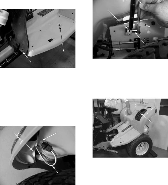
6.Remove the hex bolt securing the differential lock out pedal on the left side of the unit using a 9/16 socket. Remove the “E” clip and the nylon flange bearing from the pivot shaft.
Hex Bolt
Nylon Flange
Bearing
Differential Lock
Out Pedal
E-Clip
FIGURE 3.
7.Remove both rubber floor pads from the running boards. See figure 4.
8.Lift the hood and remove the battery cover.
9.Remove both side panels from the tractor by raising the latches horizontally and turning the latches 1/4 turn. See figure 4.
10.Loosen all four plastic wing nuts holding the dash panel screen in place. See figure 4.
11.Pull the dash screen towards the rear of the unit and out of the dash panel. See figure 4.
Side Panel Latch
Wing
Nut
Dash
Screen
Rubber Foot Pads
Side Panel Latch
FIGURE 4.
3 - 1
Cub Cadet 3000
12.Remove all four running board hex bolts from the tractor using a 1/2” socket. See figure 5.
NOTE: There are two bolts fastening the running boards to the frame where the foot pads connect and there are two bolts fastening the running boards to the dash panel.
Hex Bolt
Hex Bolt
FIGURE 5.
13.Remove the fuel cap.
14.Remove the tail light sockets from the tail light assemblies by pushing in on the sockets gently and twisting a 1/4 turn. See figure 6.
NOTE: When pulling the sockets out of the tail light assemblies, it is very important to make sure the light bulbs come straight out, or the light bulbs will fall into the tail light assemblies. Also, note the color of the wires for reinstallation. The white wires go to the reverse lights. See figure 6.
Tail |
Reverse |
Light |
Light |
White Wire for Reverse
FIGURE 6.
15.Raise the rear fender high enough to access the hydraulic lift handle clamp. See figure 7.
16.Loosen the clamp connecting the hydraulic lift handle to the center lift valve using a 1/2” socket.
Hydraulic Lift
Handle Clamp
1/2" Socket
FIGURE 7.
17.Remove the lift handle from the tractor through the slot in the flap. See figure 8.
NOTE: If the lever is not removed at this time, damage may occur to the lift knob.
18.Raise and remove the fender assembly.
Slot for
Lift Handle
FIGURE 8.
19. Reinstall the fuel cap.
3 - 2
Cub Cadet 3000
4 - 1
Cub Cadet 3000
4 - 2
Cub Cadet 3000
4 - 3
Cub Cadet 3000
4 - 4

Cub Cadet 3000
4 - 5

Cub Cadet 3000
4 - 6
Cub Cadet 3000
4 - 7
Cub Cadet 3000
4 - 8
Cub Cadet 3000
4 - 9
Cub Cadet 3000
4 - 10
Cub Cadet 3000
4 - 11
Cub Cadet 3000
4 - 12
 Loading...