

CREATOR SPRO-CON9000 User Manual
User
User’’ss
Manual
Manual
for
for
SPRO
SPRO
Network
Network
Control
Control
Host
Host
Series
Series
V1.0
V1.0
CREATOR Corporation China
CREATOR CORPORATION(CHINA
)
Meaning of the symbols
■ Safety Instruction
Symbols are used in the Manual and devices, referring to the possible risk to users or others , as well as the
damage to property, for helping you to safely and properly use the devices. The instruction and the implications
are as follows. Please make sure your correct understanding of these instructions before using the Manual.
To remind user to conduct according to the attached
operation and maintenance instructions. If ignore
Warning
Caution
these information, death or injury could possibly
happen.
To remind the user that the risky uninsulated voltage
in the device could caused electric shock to human.
Caution: To avoid electric shock, please don't open
the case, nor put the useless parts in it. Please
contact with qualified service staff.
CE authentication indicates the product is in line
with the EU safety regulation, and for assurance of
safety use.
SGS Authentication indicates the product has
reached the QC standard of the global-biggest Swiss
universe surveyor.
This product has acquired the ISO9001 International
Quality Authentication (Authentication authority:
Germany Rheinland TUV)
■ General Information Instruction
List the situation of causing unsuccessful operation
or setup, and relevant information needed to notice.
Lead to the page with detailed information on
relevant topic.

Important Notices
Caution
To ensure the device in reliable use and personal
safety, please abide by the following items when in
installation, use and maintenance:
Notice in installation
◆ Please DO NOT use the product in following
places: the places with dust, oily smoke, electrical
conductive dust, corrosive gas, inflammable gas; the
places with high temperature, due, rain and wind
exposures; the places endangered by shock and
vibration. Electric shock, fire and incorrect operation
could also cause damage and deterioration to the
product.
◆ When conducting screw drilling and wiring
process, DO NOT let metal irons and wire lead drop
into the controller and air vent, which could possibly
cause fire, failure and accidental operation.
◆ After finishing the installation, it is necessary to
ensure there is no foreign matter including the
packing material like contact paper on the ventilation
surface, otherwise, it could cause poor heat
dissipation while running, as well as fire, failure and
accidental operation.
◆ Avoid conducting wiring and plugging in/out
cable socket with electricity, otherwise, electric shock,
circuit damage could easily happen.
◆ Installation and wiring should be firm and reliable.
Poor contact could cause malfunction.
◆ With regard to the application situations with
strong interference, shielded cable should be used for
the input and output of HF signal, to improve the
anti-interference performance of the system.
Note in Wiring
◆ Installation and wiring shouldn't be conducted
until external electric power is cut off, otherwise,
electric shock or device damage could happen.
◆ The product is grounded by the earth lead of the
power cable. To avoid electric shock, the earth lead is
necessary to be connected with the ground. Before
making connection with the output end or input end
of the product, please ensure it is correctly grounding.
◆ Upon finish wiring, remove the sundries. Please
cover up the terminal plate for avoiding electric
shock.
Note for Operation and Maintenance
◆ Please DO NOT touch the terminal when with
electricity, otherwise, electric shock could happen.
◆ Don't clean up and screw the terminal tight
before power is off. Such operation could cause
electric shock when with electricity.
◆ Please turn off the power before connecting or
disconnecting the communication signal cable,
peripheral modules or control units, otherwise, device
could be damaged and accidental operation could
happen.
◆ Please DO NOT disassemble the device, so as to
avoid internal electric components damage.
◆ It is necessary to read through the Manual and
fully ensure the safety, before altering the program,
trial running, starting and stopping operation.
◆ Button battery shouldn't be replaced before the
power is off. If it has to be replaced when the device
is running, it should be conducted by professional
electric technician wearing insulated gloves.

Note for declaration of the worthless.
When declaring of worthless, please note
◆ Explosion of electrolytic capacitor on the circuit
board could happen when burning it.
◆ Please classify and dispose it. Don't dispose it into
household garbage.
◆ Please deal it as industrial waste, or in accordance
with local environmental protection regulation.
Forward
User’s Manual for SPRO Network Control Host Series mainly introduces the operation manner, primary
parameters and trouble shootings of SPRO-CAV801 、 SPRO-CAV802 、 SPRO-CON9000 、
SPRO-CON9100、and SPRO-CON9200 network control hosts
The Manual serves as user's operation instruction only, rather than for maintenance service purpose. Since the
date of release, any function or relevant parameter alteration will be provided in supplement instruction. Please
refer to the manufacturer or dealers for inquiry.
CREATOR Electronics own the copyright of the Manual. Without permission, any unit or person shall not take
part or total of the Manual for business purpose.
The copyright of the Manual is protected by Copyright Law of People’s Republic of China and other Intellectual
Property Law. Without written permission, any copy or distribution is prohibited.

Index
Chapter 1 General Introduction.............................................................................................................................1
1.1 Functions and Features.......................................................................................................................... 1
1.2 Components of the Product................................................................................................................... 1
1.3 Accessory and Compatiable Products................................................................................................. 1
1.4 Device Installation....................................................................................................................................2
Chapter 2 Introduction to the Host........................................................................................................................3
2.1 Front Panel................................................................................................................................................3
2.2 Rear Panel................................................................................................................................................ 5
2.3 Introduction to Part of Ports in the Host...............................................................................................7
2.3.1 COM Port Function.................................................................................................................... 7
2.3.2 CR-NET Connection.................................................................................................................. 7
2.3.3 USB Port Connection.................................................................................................................7
2.3.4 Audio Port Connection...............................................................................................................7
2.4 System Connection Diagram................................................................................................................. 8
2.4.1 SPRO-CAV802 System Connection....................................................................................... 8
2.4.2 SPRO-CON9200 System Connection.................................................................................... 9
2.4.3 Connection between SPRO Series Host and Wireless(RF)Touch Screen.................9
2.4.4 Connection between SPRO Series Host and Wireless(WiFi)Touch Screen............ 10
2.4.5 Connection between SPRO Series Host and Wired(CR-NET)Touch Screen..........10
2.4.6 Connection between SPRO Series Host and Wired Ethernet Touch Screen................11
Chapter 3 Receiver...............................................................................................................................................12
3.1 CR-WF10 Wireless AP (Acess Point)................................................................................................ 12
3.1.1 CR-WF10 Configuration..........................................................................................................12
3.1.2 Connection................................................................................................................................ 15
3.2 Wireless One-way Receiver CR-RFA................................................................................................ 15
3.2.1 Use Guide..................................................................................................................................15
3.3 Wireless Two-way Receiver CR-TRA................................................................................................ 16
3.3.1 Use Guide..................................................................................................................................16
Chapter 4 Introduction to Infrared Transmission Stick ...............................................................................17
4.1 Functions and Features........................................................................................................................17
4.2 Connection..............................................................................................................................................17
Chapter 5 Software Introduction.........................................................................................................................18

5.1 Control System Programming Software............................................................................................ 18
5.1.1 Installation of Control System Programming Software......................................................18
5.1.2 Monitor Manager Software..................................................................................................... 18
5.1.3 User’s Project Download .......................................................................................................19
5.2 IR Manager- Infrared Code Management Software........................................................................ 20
5.3 Touch Panel- Application of Touch Screen Programming Software.............................................20
5.3.1 User’s Project Download.........................................................................................................20
Chapter 6 Performance Parameters..................................................................................................................22
Chapter 7 General Trouble Shootings...............................................................................................................23

1
User’s Manual for SPRO Network Control Host Series
Chapter 1 General Introduction
SPRO Network Control Host Series is the new
generation network communication control host
released by CREATOR, adopting 210MHz 32-bit
imbedded processor, ARM7 CPU, 32M memory
and 2M Flash memory.
SPRO Network Control Host Series provides
CR-NET and Ethernet with multiple control ports
including IR (Infrared), I/O (digit input/output),
Relay and COM ports.
Adopting advanced integrated technology,
providing high-speed and accurate centralized
control environment, with open user’s
programming interface, for completing the
programming of a variety of complicated control
interfaces.
1.1 Functions and Features
◆ Adopting European and US design in smooth
lines, incorporated with fashionable and
innovative idea.
◆ ARM7 CUP , 32M memory , 2M Flash
memory.
◆ Adopt 210M GHz 32-BIT imbedded processor
◆ 4/8-way independent programmable infrared
transmission port, supporting the control of
multiple same or different infrared devices.
◆3/4/8-way independent programmable
RE-232/422/485 control ports. User may program
and configure a variety of control protocols and
codes.
◆ 4/8-way light-current relay ports
◆ 4/8-way digital input/output ports
◆ Two types of network communication :
CR-NET、Ethernet;
◆ USB2.0 programming communication port
◆ Built-in infrared learner, convenient for
fine-tuning and maintenance.
◆ Support local and remote control ways
◆ Universal wide-adaptive power design
(AC100~240V),
It is suitable for use in any country and region.
1.2 Components of the Product
SPRO Network Control Host Series includes 5
hosts. They are SPRO-CAV801, SPRO-CAV802,
SPRO-CON9000, SPRO-CON9100 and
SPRO-CON9200
1.3 Accessory or Compatible
Products
◆ Touch Screen
CR-Wifi G4/G5/G6/G7/G8
4.3、5.7、6.4、7.0、8.4 inch wireless(WIFI)touch
screen
CR-LAN G10/G12/G15
10.2、12.1、15.1 inch wired(Ethernet)two-way
touch screen
ST-7600C
7.0 inch wireless (RF) one-way touch screen
MT430/LT-5100BW/6500C/7000C/1200C/1300C
CREATOR Corporation China 2010-05 WWW.CREATOR1997.COM
2
User’s Manual for SPRO Network Control Host Series
4.3、5.7、6.4、12.1 inch wired(CR-NET) two-way
touch screen
DTX-7900C
7.0 inch wireless (TR) two-way touch screen
◆ Remote Controller
CR-Wifi G3
Wireless (WiFi) Two-way Controller
◆ On-wall Panel
CR-WM8/16
8/16 keys on-wall panel connects to the host in
wired (CR-NET) mode.
Other CR-NET BUS Devices
CR-PWR-4/8 4/8-way heavy-current relay
CR-LITE-4A/B 4-way light modulator
CR-VOL Volume controller
◆ Wireless Transmission Device
CR-WF10
Wireless AP is used along with CREATOR
wireless (WiFi) two-way touch screen.
CR-RFA
Wireless one-way receiver is used along with
CREATOR wireless (RF) one-way touch screen.
CR-TRA
Wireless two-way receiver is used along with
CREATOR wireless (TR) two-way touch screen.
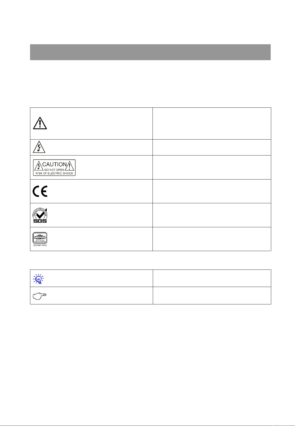
1.4 Devices Installation
SPRO Network Control Host Series can be
installed in a standard 19-inch cabinet, with
accessory of a pair of installation stands. See the
following assembling manner:
CREATOR Corporation China 2010-05 WWW.CREATOR1997.COM
3
User’s Manual for SPRO Network Control Host Series
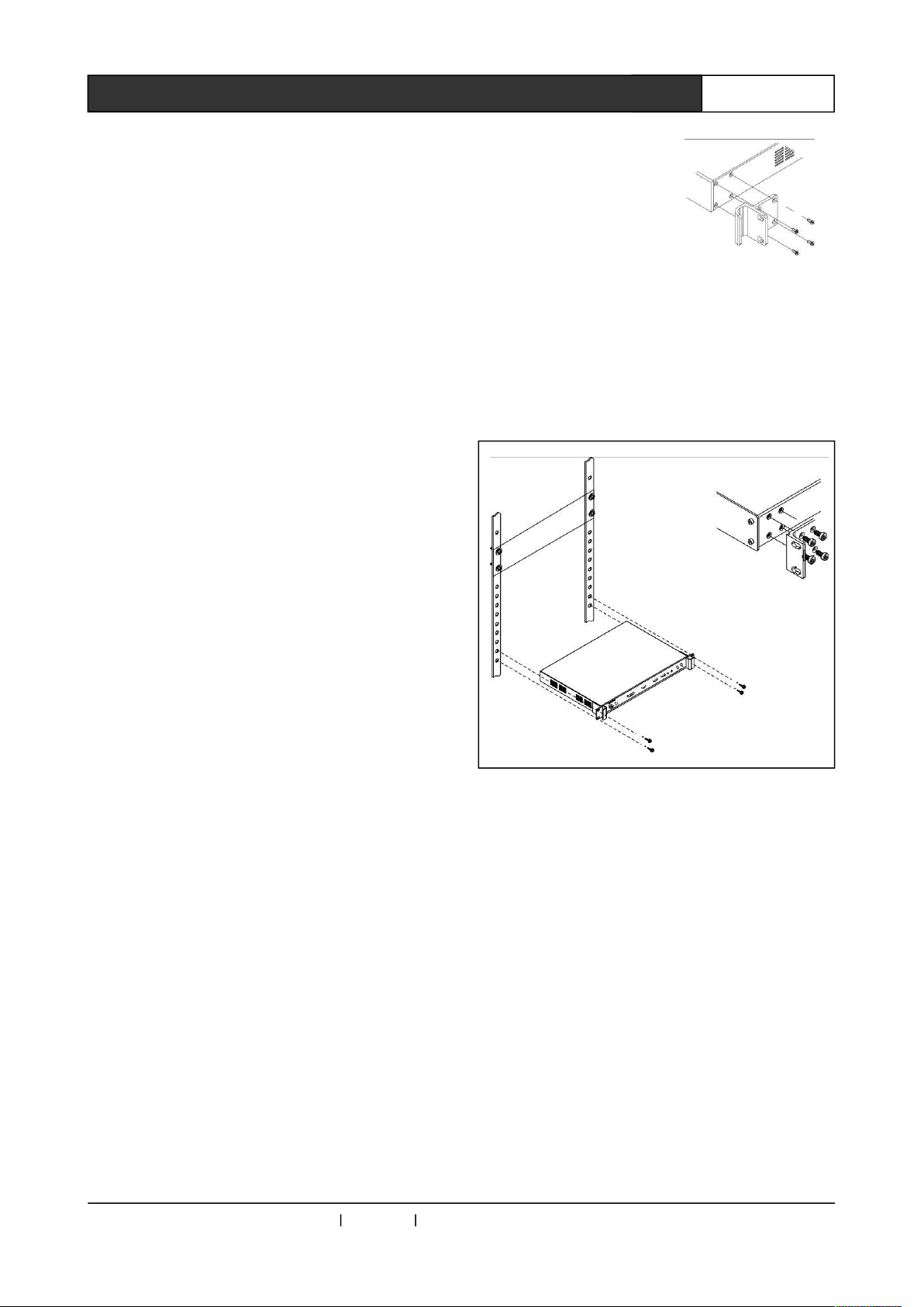
2.1 Front Panel
1) POWER—— Power indicator
ACTIVE—— Signal status indicator
2) RS-232/422/485——COM data
SPRO-CAV801:
SPRO-CAV802:
SPRO-CON9000:
SPRO-CON9100:
SPRO-CON9200:
Chapter 2 Introduction to System Host
CREATOR Corporation China 2010-05 WWW.CREATOR1997.COM
 Loading...