

Page 1
Single
Single
Core
Core
Optical
Optical
Fiber
Fiber
Transmitter
Transmitter
User's
User's
Manual
Manual
V1.0 Version
CREATOR CORPORATION CHINA
CREATOR CORPORATION(CHINA)
Page 2
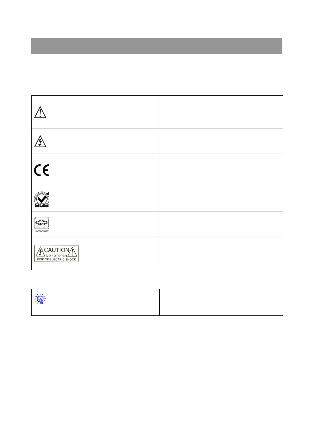
The meaning of symbols
This is A level product, which may cause radio
interference in the living environment. In this
case, users may need to take the feasible
measures to get around the interference.
CE certification means that the product has
reached the directive safety requirements
defined by the European Union. Users can be
assured about the use of it
Warning; in order to avoid electrical shock, do
not open the machine cover, nor is the useless
part allowed to be placed in the box. Please
contact the qualified service personnel.
■Safety instructions
For your safe and correct use of equipments, we use a lot of symbols on the equipments and in the
manuals, demonstrating the risk of body hurt or possible damage to property for the user or others.
Indications and their meanings are as follow. Please make sure to correctly understand these
instructions before reading the manual.
Remind users that the dangerous voltage
without insulation occurring within the
equipment may cause people suffer from shock
SGS certification means that the product has
reached the quality inspection standards
proposed by the world's largest SGS.
This product passed the ISO9001 international
quality certification (certification body; TUV
Rheinland, Germany).
■General information instructions
It lists the factors leading to the unsuccessful
operation or set and the relevant information to
pay attention to.
Page 3

Important note
Warning
In order to ensure the reliable performance of the
equipment and the safety of the user, please
observe the following matters during the process
of installation, use and maintenance;
The matters needing attention of installation
◆Please do not use this product in the following
places; the place of dust, soot and electric
conductivity dust, corrosive gas, combustible gas;
the place exposed to high temperature,
condensation, wind and rain; the occasion of
vibration and impact . Electric shock, fire, wrong
operation can lead to damage and deterioration
to the product, either;
◆In processing the screw holes and wiring,
make sure that metal scraps and wire head will
not fall into the shaft of controller, as it could
cause a fire, fault, or incorrect operation;
◆When the installation work is over, it should be
assured there is nothing on the ventilated face,
including packaging items like dust paper.
Otherwise this may cause a fire, fault, incorrect
operation for the cooling is not free;
◆Should avoid wiring and inserting cable plug in
charged state, otherwise it is easy to cause the
shock, or electrical damage;
◆The installation and wiring should be strong
and reliable, contact undesirable may lead to
false action;
◆For a serious interference in applications,
should choose shield cable as the high frequency
signal input or output cable, so as to improve the
anti-jamming ability of the system.
Attention in the wiring
◆Only after cutting down all external power
source, can install, wiring operation begin, or it
may cause electric shock or equipment damage;
◆This product grounds by the grounding
wires .To avoid electric shocks, grounding wires
and the earth must be linked together. Before the
connection of input or output terminal, please
make sure this product is correctly grounded;
◆Immediately remove all other things after the
wiring installation. Please cover the terminals of
the products cover before electrification so as to
avoid cause electric shock.
Matters needing attention during operation
and maintenance
◆Please do not touch terminals in a current
state, or it may cause a shock, incorrect
operation;
◆Please do cleaning and terminal tighten work
after turning off the power supply. These
operations can lead to electric shock in a current
state;
◆Please do the connection or dismantle work of
the communication signal cable , the expansion
module cable or control unit cable after turning
off the power supply, or it may cause damage to
the equipment, incorrect operation;
◆Please do not dismantle the equipment, avoid
damaging the internal electrical component;
◆Should be sure to read the manual, fully
confirm the safety, only after that can do program
changes, commissioning, start and stop
operation.
Matters needing attention in discarding
product
◆Electrolytic explosion; the burning of
electrolytic capacitor on circuit boards may lead
to explosion;
◆Please collect and process according to the
classification, do not put into life garbage;
◆Please process it as industrial waste, or
according to the local environmental protection
regulations.
Page 4

Preface
This manual is only used as user instruction, not for a repair service usage. The functions or related
parameters may be changed since the date of issue, please inquire the supplemental information from
CREATOR Electronics or local distributors.
The copyright of this manual belongs to CREATOR Electronics. Without permission, no unit or
individual shall adopt part or all of its content for commercial use.
The manual is protected by of the Copyright Law of the Peoples Republic of China and other
regulations about intellectual property rights. Without written permission shall not be copied or
distributed.
Page 5

Catalog
Chapter 1 Summary.................................................................................................................................................. 1
1.1 Function Characteristics..........................................................................................................................1
1.2 Product Types........................................................................................................................................... 1
Chapter 2 Controller Description.............................................................................................................................2
2.1 CR-uSF AV 200T Transmitter.................................................................................................................2
2.1.1 Function Characteristics.............................................................................................................. 2
2.1.2 Panel Description..........................................................................................................................2
2.1.3 Connection Diagram.....................................................................................................................3
2.2 CR-Usf D 200T Transmitter.................................................................................................................... 3
2.2.1 Function Characteristics.............................................................................................................. 3
2.2.2 Panel Description..........................................................................................................................4
2.2.3 Connection Diagram.....................................................................................................................5
2.3 CR-uSF DVI 200R Receiver...................................................................................................................5
2.3.1 Function Characteristics.............................................................................................................. 5
2.3.2 Panel Description..........................................................................................................................5
2.3.3 Connection Diagram.....................................................................................................................6
2.4 CR-uSF HDMI 200R Receiver............................................................................................................... 6
2.4.1 Function Characteristics.............................................................................................................. 6
2.4.2 Panel Description..........................................................................................................................6
2.4.3 Connection Diagram.....................................................................................................................7
2.5 CR-uSF VGA 200R Receiver................................................................................................................. 7
2.5.1 Function Characteristics.............................................................................................................. 7
2.5.2 Panel Description..........................................................................................................................7
2.5.3 Connection Diagram.....................................................................................................................8
Chapter 3 Technical Parameters............................................................................................................................. 9
3.1 CR-uSF AV 200T Parameters................................................................................................................ 9
3.2 CR-uSF HD 200T Parameters.............................................................................................................12
3.3 CR-uSF DVI 200R Parameters........................................................................................................... 14
3.4 CR-uSF HDMI 200R Parameters........................................................................................................16
3.5 CR-uSF VGA 200R Parameters.......................................................................................................... 18
Chapter 4 Accessories............................................................................................................................................ 21
4.1 Infrared Transmitter CR-IR/T............................................................................................................... 21
4.2 Infrared Receiver CR-IR/R................................................................................................................... 21
4.3 3.5mm Headset Connector to DB9 Male Socket Connecting Line............................................... 21
4.4 3.5mm Headset Connector to DB9 Female Socket Connecting Line...........................................21
4.5 DB15 Male Socket to RCA Terminal, SV Terminal Connection Line (VGA to CV video, Y/C
video, YPbPr video).........................................................................................................................................21
Page 6

Single Core Optical Fiber Transmitter User's Manual
1
CR-uSF AV/HD 200T, CR-uSF VGA/DVI/HDMI
200R are five multimode single core optical fiber
transmission products. They are optical
transmitter transmitting
CV/YC/YPbPr/VGA/DVI/HDMI video and
synchronous audio signal, IR signal, RS-232
signal through the single core optical fiber. And
they support mixed transmission, remote
transmission, high-definition signal transmission
and other functions.
This series of products are mainly used in radio
and television engineering, multimedia
conference hall, large screen display works,
television instruction, command and control
centers and other occasions.
1.1 Function Characteristics
Support multiple signal types like CV, YC,
YPbPr, VGA, DVI, HDMI, etc.;
Support IR, RS-232 signal passing through;
Transmission distance is up to 300M, when
using the SC optical interface;
DC12V external power supply.
1.2 Product Types
CR-uSF AV 200T (multi format video single
core optical fiber transmitter)
CR-uSF HD 200T (HDMI and DVI video
single core optical fiber transmitter)
CR-uSF DVI 200R (DVI video single core
optical fiber receiver)
CR-uSF HDMI 200R (HDMI video single core
optical fiber receiver)
CR-uSF VGA 200R (VGA video single core
optical fiber receiver)
Chapter 1 Summary
CREATOR CHINA 2013-08 WWW.CREATOR1997.COM
Page 7
Single Core Optical Fiber Transmitter User's Manual
2
Chapter 2 Controller Description
2.1 CR-uSF AV 200T
Transmitter
CR-uSF AV 200T is a single core multimode
optical fiber transmitter supporting multiple format
component video. It can convert CV, Y/C, YPbPr,
VGA, DVI, HDMI video signals and Audio signal
into optical signal for transmission. It can be used
together with the matrix. It supports RS-232 and
IR passing through.
2.1.1 Function Characteristics
Support for single core multi-mode fiber to
transmit CV, Y/C, YPbPr, VGA, DVI, and
HDMI signals;
With HDMI-Monitor video output monitor
function;
Support transmission of synchronous Audio
signal, IR signal and RS-232 signal;
Support the field refresh EDID;
Transmission distance is up to 300M.
2.1.2 Panel Description
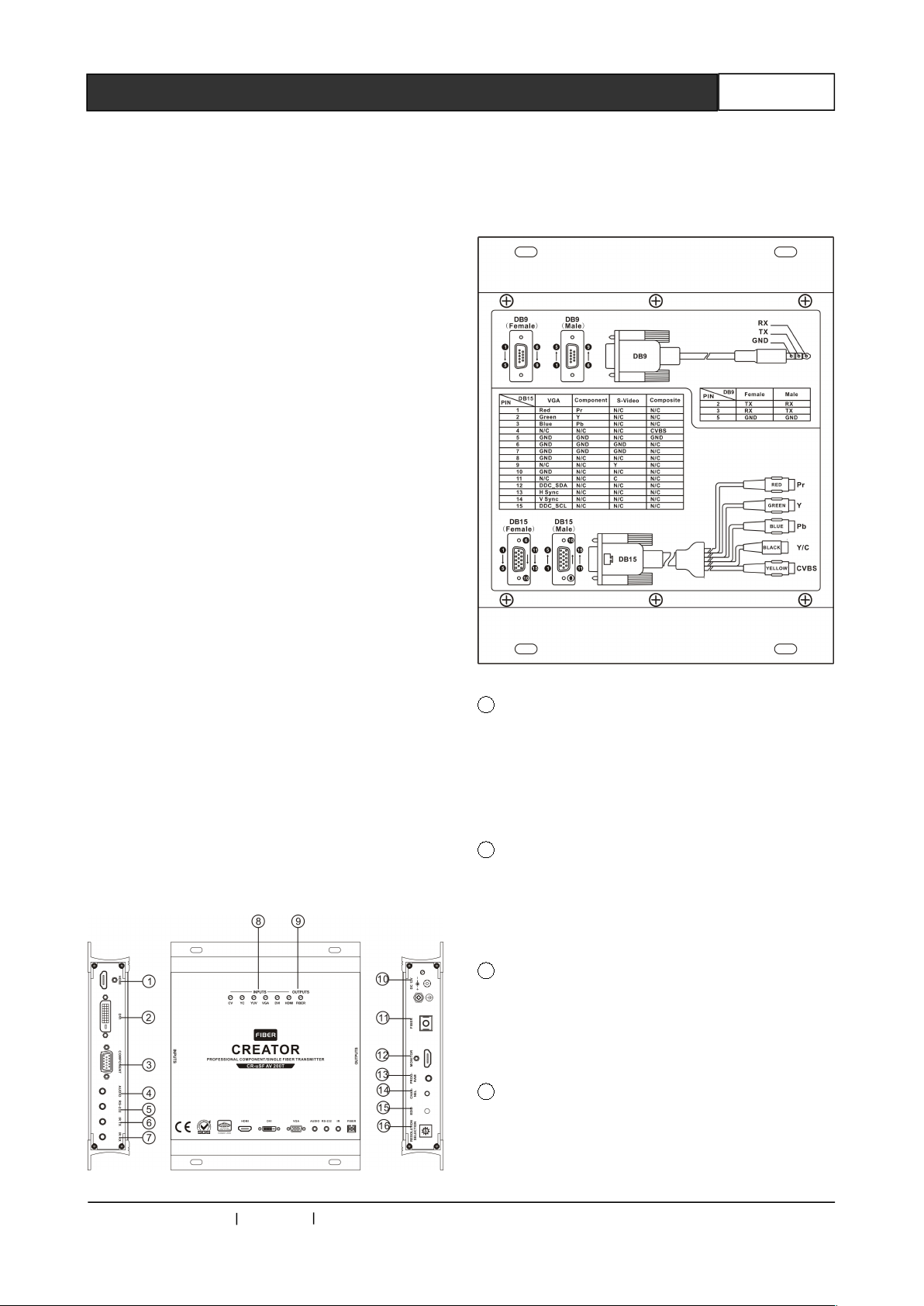
CR-uSF AV 200T front panel:
CR-uSF AV 200T rear panel:
1 HDMI——HDMI audio and video input
interface
Support one-way HDMI audio and video signal
input, using HDMI-A interface, used in PC and
other peripheral equipments.
2 DVI——DVI video input interface
Support one-way DVI video signal input, using
DVI-D interface, used in PC and other peripheral
equipments.
3 COMPONENT——Composite video input
interface
Support VGA, Y/C, CV, YPbPr video signal input,
using DB15 female interface.
4 AUDIO——Audio input interface
Support one-way 3.5mm unbalanced stereo
audio input.
CREATOR CHINA 2013-08 WWW.CREATOR1997.COM
Page 8
Single Core Optical Fiber Transmitter User's Manual
3
5 RS-232——Serial through interfaces
6 IR TX——Infrared transmitting interface
Connected with the infrared transmitter to
transmit the infrared signal from optical fiber
transmission.
7 IR RX——Infrared receiving interface
Connected with the infrared receiver to receive
infrared signal from remote control etc.
8 INPUTS——Video input indicator
9 OUTPUTS——Fiber connection indicator
10 DC 12V——Power and lights
CR-uSF AV 200T power supply and the power
indicator light, the indicator lights up when the
controller is powered normally.
11 FIBER——Optical fiber output interface
One-way fiber signal output, used for optical
signal transmission.
12 MONITOR——video monitoring output
interface
Support One-way local video monitoring output,
using HDMI-A interface, used in display and other
peripheral equipments.
13 PROGRAM——Function configuration
interface
Used to configure the parameters for the
machine.
14 CHANNEL——Channel selection button
Press this button to switch different signal
inputs.
15 EDID——EDID read and write keys
Press the key to read and write EDID, used for
copy the EDID of display device connected to the
local device.
16 RESOLUTION SELECTION——Resolution
selection switcher
This switcher is used to switch the different output
resolutions, 10 resolutions are optional.
800 x 600@60Hz
1024 x 768@60Hz
1280 x 720P@60Hz
1280 x 800@60Hz
1280 x 1024@60Hz
1366 x 768@60Hz
1440 x 900@60Hz
1400 x 1050@60Hz
1600 x 900@60Hz
1920 x 1080P@60Hz
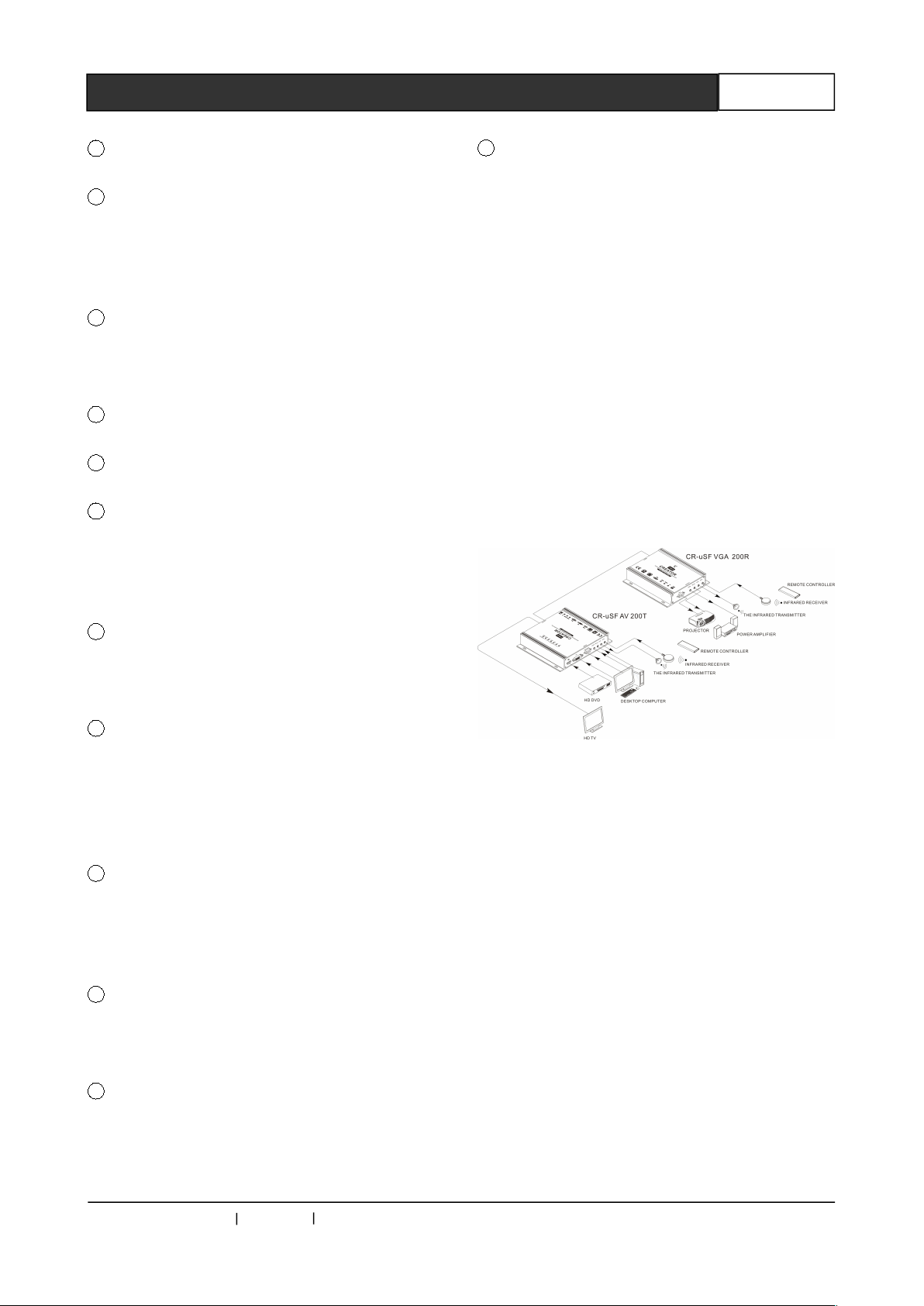
2.1.3 Connection Diagram
2.2 CR-Usf D 200T Transmitter
CR-uSF HD 200T is a single core multimode
optical fiber transmitter supporting high resolution
HDMI, DVI signals. It can convert HDMI video
signal into optical signal for transmission, and can
be used with single core optical fiber transmission
receiver or fiber matrix; supports for RS-232 and
IR passing through.
2.2.1 Function Characteristics
Support single core multi-mode fiber
transmission of high resolution of HDMI
signal;
Support single core multi-mode fiber
transmission of high resolution of DVI signal;
CREATOR CHINA 2013-08 WWW.CREATOR1997.COM
Page 9
Single Core Optical Fiber Transmitter User's Manual
4
Support transmission of Audio signal, IR
signal and RS-232 signal;
Support the field refresh EDID;
Transmission distance is up to 300M.
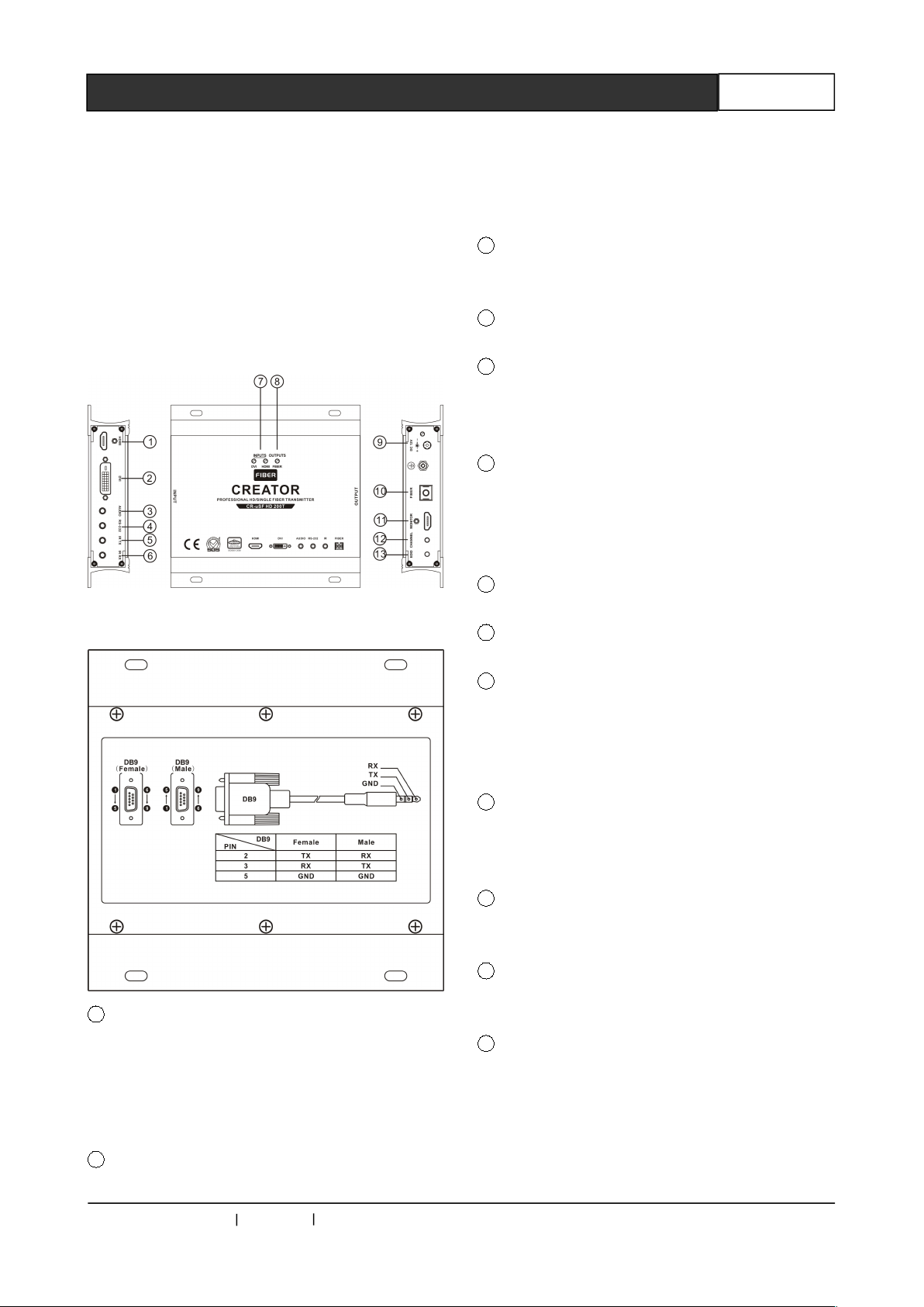
2.2.2 Panel Description
CR-uSF HD 200T front panel:
CR-uSF HD 200T rear panel:
1 HDMI——HDMI audio and video input
interface
Support one-way HDMI audio and video signal
input, using HDMI-A interface, used in PC and
other peripheral equipments.
2 DVI——DVI video input interface
Support one-way DVI video signal input, using
DVI-D interface, used in PC and other peripheral
equipments.
3 AUDIO——Audio input interface
Support 1 3.5mm unbalanced stereo audio input.
4 RS-232——Serial through interfaces
5 IR TX——Infrared transmitting interface
Connect the infrared transmitter to transmit the
infrared signal from optical fiber transmission.
6 IR RX——Infrared receiving interface
Connected with the infrared receiver to
receive infrared signal from remote control
etc..
7 INPUTS——Video input indicator
8 OUTPUTS——fiber connection indicator
9 DC 12V——Power and lights
CR-uSF HD 200T power supply and the power
indicator light, the indicator lights up when
controller is powered normally.
10 FIBER——Optical fiber output interface
One way fiber signal output, is used for optical
signal transmission.
11 MONITOR——Video monitoring output
interface
12 CHANNEL——Channel selection button
Press this button to switch different signal inputs.
13 EDID——EDID read and write key
Press the key to read and write EDID, used for
copy EDID of local connected display device.
CREATOR CHINA 2013-08 WWW.CREATOR1997.COM
Page 10
Single Core Optical Fiber Transmitter User's Manual
5
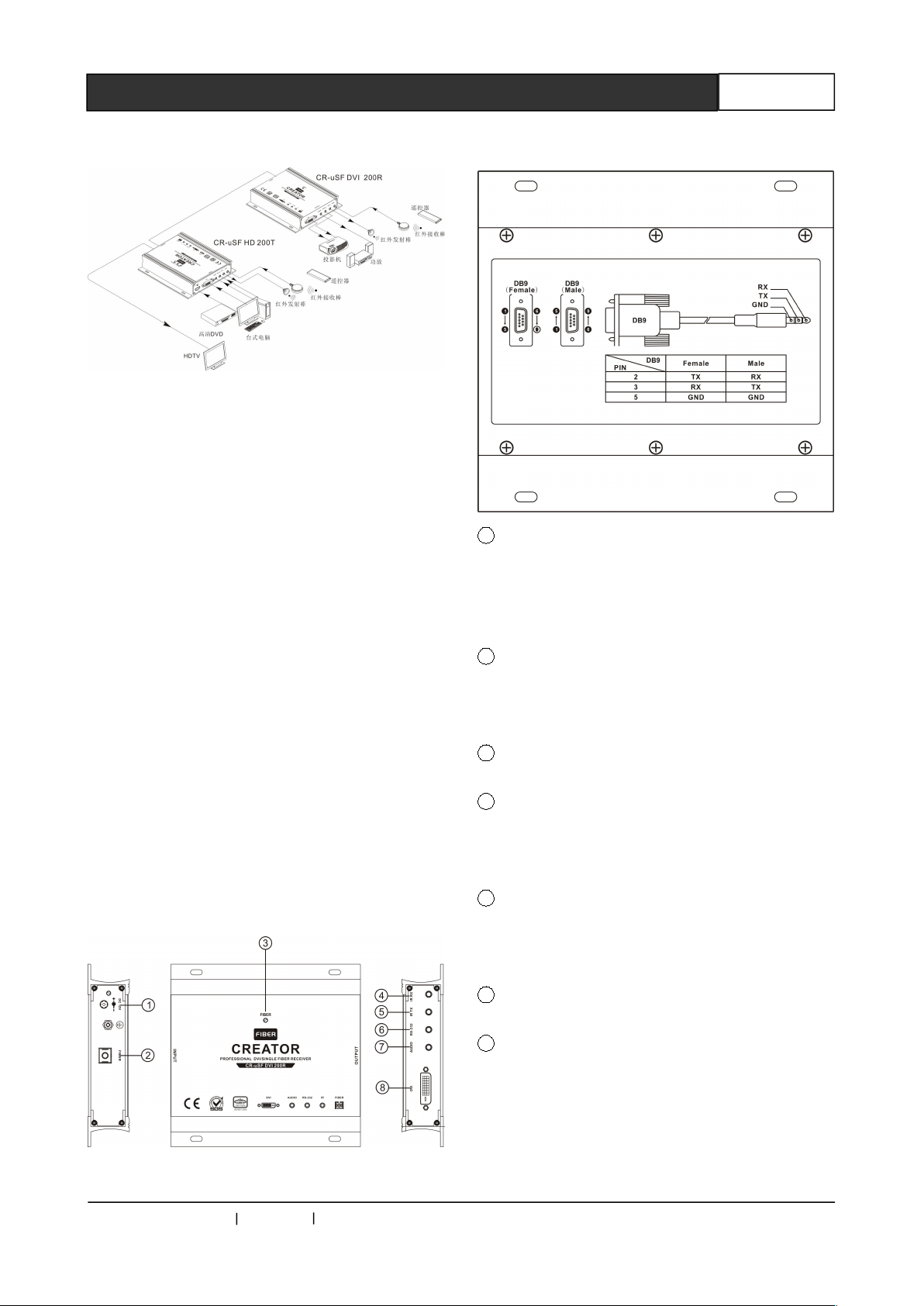
2.2.3 Connection Diagram
2.3 CR-uSF DVI 200R Receiver
CR-uSF DVI 200R is a single core multimode
fiber transmission receiver supporting high
resolution DVI signal. It can restore the received
optical signal to the HD DVI signal and audio
signal, and can be used with CR-uSF HD 200T or
fiber matrix; supports for RS-232 and IR passing
through.
2.3.1 Function Characteristics
support single core multi-mode fiber
transmission of high resolution of DVI signal;
Support transmission of Audio signal, IR
signal and RS-232 signal;
Transmission distance is up to 300M.
2.3.2 Panel Description
CR-uSF DVI 200R front panel:
CR-uSF DVI 200R rear panel:
1 DC 12V——Power and lights
CR-uSF DVI 200R power supply and the power
indicator light, the indicator lights up when
controller is powered normally.
2 FIBER——Optical fiber input interface
One way fiber signal input, is used for optical
signal transmission.
3 NPUTS——Fiber connection indicator
4 IR RX——Infrared receiving interface
Connected with the infrared receiver, receiving
infrared signals of remote control etc.
5 IR TX——infrared transmission interface
Connect the infrared transmitter, transmitting
infrared signal from optical fiber transmission.
6 RS-232——Serial through interfaces
7 AUDIO——Audio input interface
Support one way 3.5mm unbalanced stereo audio
input.
CREATOR CHINA 2013-08 WWW.CREATOR1997.COM
Page 11
Single Core Optical Fiber Transmitter User's Manual
6
8 DVI——DVI video input interface
Support one way DVI video signal input, using
DVI-D interface, used in PC and other peripheral
equipments.
2.3.3 Connection Diagram
2.4 CR-uSF HDMI 200R
Receiver
CR-uSF HDMI 200R is a single core multimode
optical fiber receiver supporting high resolution
HDMI signals. It can convert optical fiber video
signal into HDMI high-definition signal, and
should be used with CR-uSF HD 200T or matrix;
supports for RS-232 and IR passing through.
2.4.1 Function Characteristics
Support single core multi-mode fiber
transmission of high resolution of HDMI signal;
Support transmission of Audio signal, IR
signal and RS-232 signal;
Transmission distance is up to 300M.
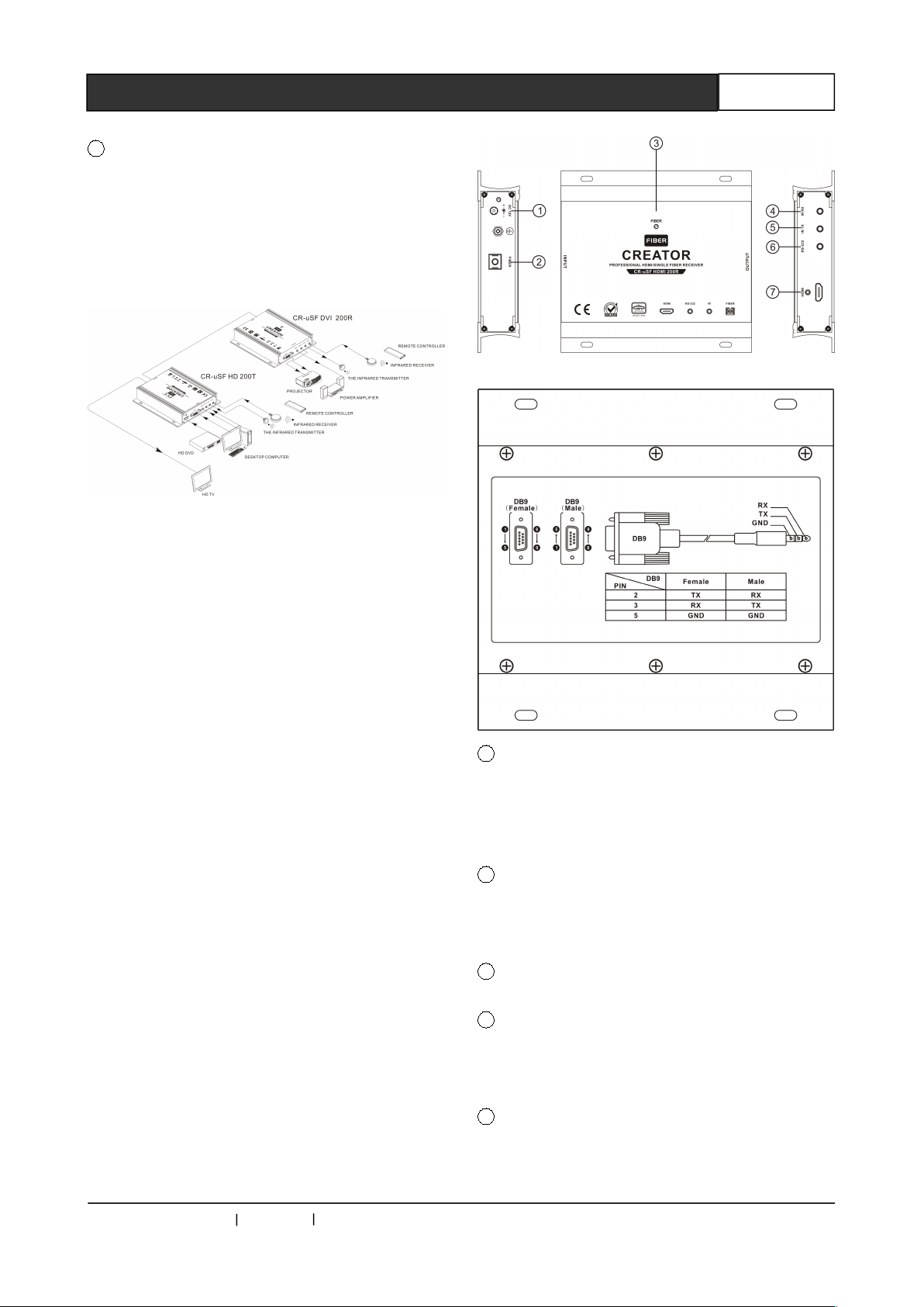
2.4.2 Panel Description
CR-uSF HDMI 200R front panel:
CR-uSF HDMI 200R rear panel :
1 DC 12V——Power and lights
CR-uSF HDMI 200R power supply and the power
indicator light, the indicator lights up when the
controller is powered normally.
2 FIBER——Optical fiber input interface
One way fiber signal input, is used for optical
signal transmission.
3 INPUTS——Fiber connection indicator
4 IR RX——Infrared receiving interface
Connected with the infrared receiver to receive
infrared signal from remote control etc.
5 IR TX——Infrared transmitting interface
Connect the infrared transmitter to transmit the
infrared signal from optical fiber transmission.
CREATOR CHINA 2013-08 WWW.CREATOR1997.COM
Page 12
Single Core Optical Fiber Transmitter User's Manual
7
6 RS-232——Serial through interfaces
7 HDMI——HDMI audio and video input
interface
Support one way HDMI audio and video signal
output, using HDMI-A interface, used in PC and
other peripheral equipments.
2.4.3 Connection Diagram
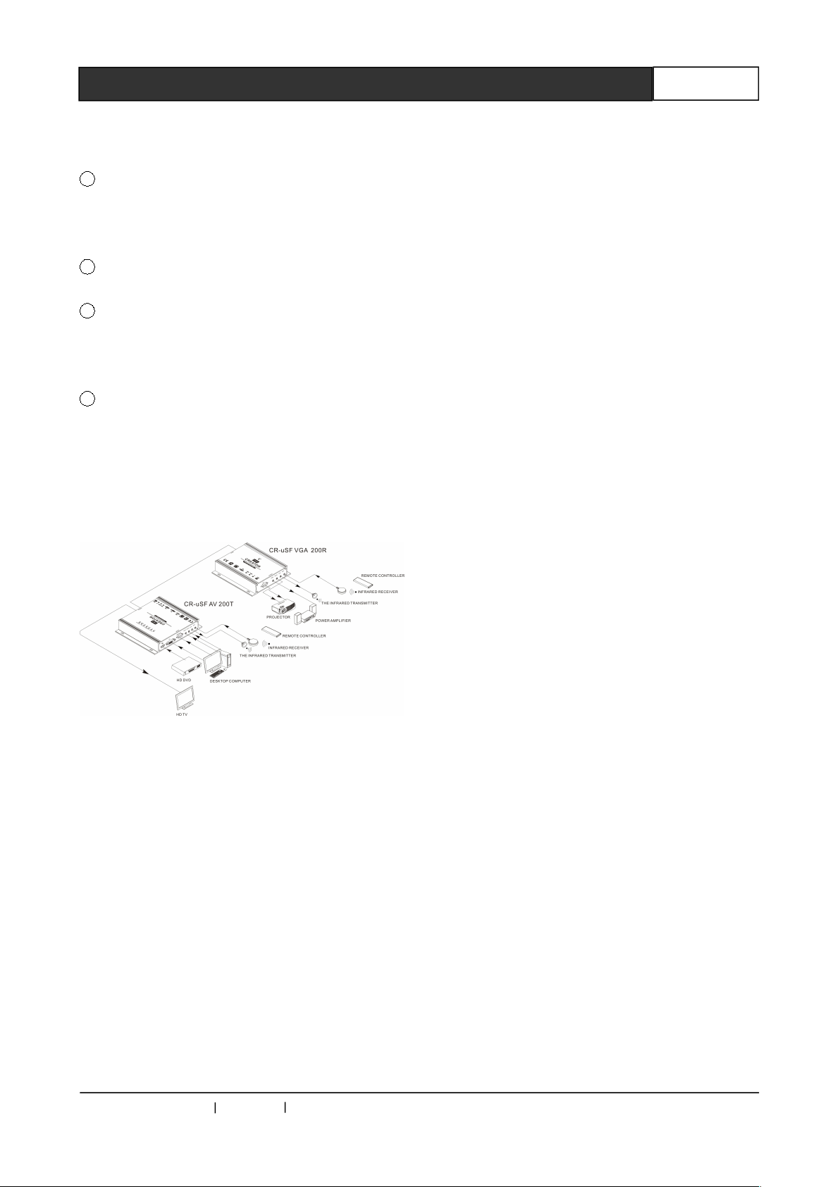
2.5 CR-uSF VGA 200R
Receiver
CR-uSF VGA 200R is a single core multimode
fiber transmission receiving terminal supporting
high resolution VGA signal. It can restore the
received optical signal to VGA signal and audio
signal, can be used with CR-uSF HD 200T or
optical fiber matrix. It supports RS-232 and IR to
pass through.
2.5.1 Function Characteristics
Support single core multi-mode fiber
transmission of high resolution of VGA
signal;
Support transmission of Audio signal, IR
signal and RS-232 signal;
Transmission distance is up to 300M.
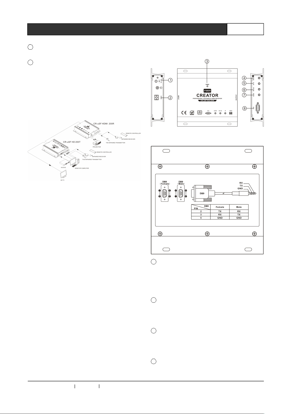
2.5.2 Panel Description
CR-uSF VGA 200R front panel:
CR-uSF VGA 200R rear panel:
1 DC 12V——Power and lights
CR-uSF VGA 200R power supply and the power
indicator light, the indicator lights up when the
controller is powered normally.
2 FIBER——Optical fiber input interface
One way fiber signal input, is used for optical
signal transmission.
3 INPUTS——fiber connection indicator
Connect the infrared transmitter to transmit the
infrared signal from optical fiber transmission.
4 IR RX——Infrared receiving interface
Connected with the infrared receiver to receive
CREATOR CHINA 2013-08 WWW.CREATOR1997.COM
Page 13
Single Core Optical Fiber Transmitter User's Manual
8
infrared signal from remote control etc.
5 IR TX——Infrared transmitting interface
Connect the infrared transmitter to transmit the
infrared signal from optical fiber transmission.
6 RS-232——Serial through interface
7 AUDIO——Audio input interface
Support one way 3.5mm unbalanced stereo audio
input.
8 VGA——VGA video output interface
It supports one way VGA video signal output,
using DB-15 interface, used in PC and other
peripheral equipments.
2.5.3 Connection Diagram
CREATOR CHINA 2013-08 WWW.CREATOR1997.COM
Page 14
Single Core Optical Fiber Transmitter User's Manual
9
Chapter 3 Technical Parameters
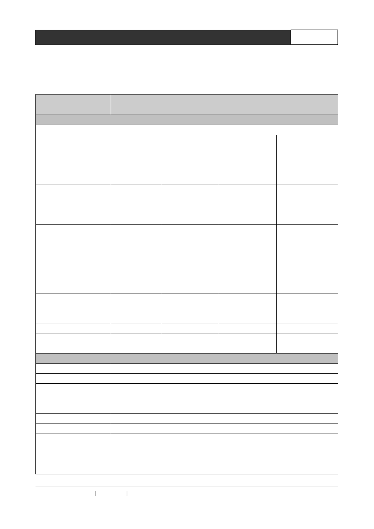
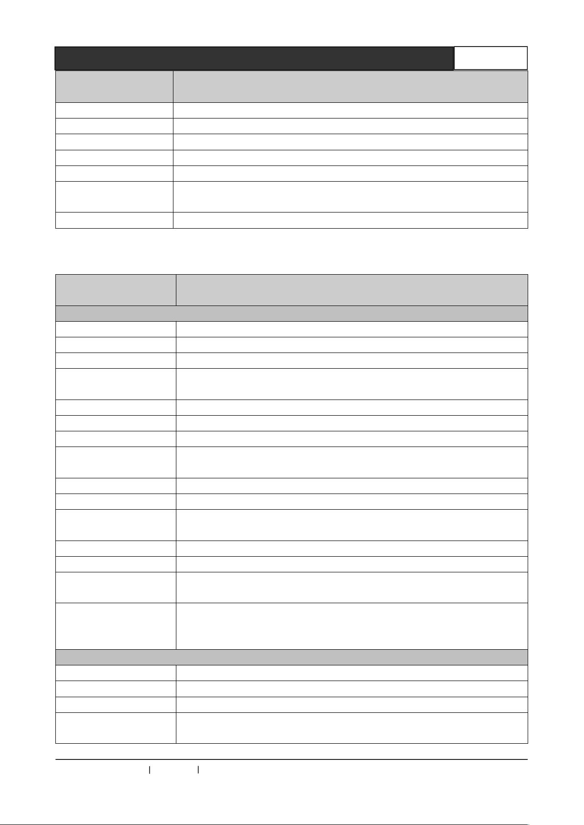
3.1 CR-uSF AV 200T Parameters
Specifications
Model
Analog video input
Interface HD-15 Interface
Signal Type
Gain 0dB 0dB 0 dB 0 dB
Bandwidth
Differential phase
error
Differential gain error
Signal Strength
Minimum / maximum
level
Input impedance 75 Ω 75 Ω 75Ω 75Ω
Echo Loss <-30dB@5MH
DVI video input
Supported protocols DVI1.0,HDMI1.3a,HDCP1.3
PIXEL Bandwidth PlXEL 165MHz , full digital
Interface bandwidth 2.25Gbps,full digital( a total of 6.75Gbps. each color is 2.25Gbps )
Maximum support
resolution
Clock Jitter <0.15 T bit
Rise time <0.3Tbit (20%--80%)
Fall time <0.3Tbit (20%--80%)
Signal Type DVI-D/ HDMI full digital T.M.D.S. signal in DVI 1.0 / HDMI 1.3a specification
Interface DVI-D Interface
Signal Strength T.M.D.S. 3.3V p-p
Composite
video CV
150MHz @
-3dB
0.1°,3.58-4.43
MHz
0.1% ,
3.58-4.43 MHz
1V p-p ;
Composite
video (CVBS)
Analog
signal ;
-2V/+2V
z
PC 1920x1200@60_24bit Color depth
HDTV 1920x1080P@60_36bit Color depth
Y/C video
150MHz @ -3dB
0.1°,3.58-4.43
0.1% , 3.58-4.43
1V p-p: S
VIDEO(Y/C)
Analog signal ;
-2V/+2V
<-30dB@5MHz <-30dB@5MHz <-30dB@5MHz
CR-uSF AV 200T
MHz
MHz
Component
videoYPbPr
350MHz @ -3dB 380 MHz
0.1°,3.58-4.43
MHz
0.1% , 3.58-4.43
MHz
1V p-p ;( Y in
component
video)
0.3Vp-p;
(PbPr/CbCr in
component
video)
Analog signal ;
-2V/+2V
VGA video
0.63V p-p to 0.9 V
p-p
RGB
signal;0V/1.0V
HV signal:0V/5.0V
CREATOR CHINA 2013-08 WWW.CREATOR1997.COM
Page 15
Single Core Optical Fiber Transmitter User's Manual
10
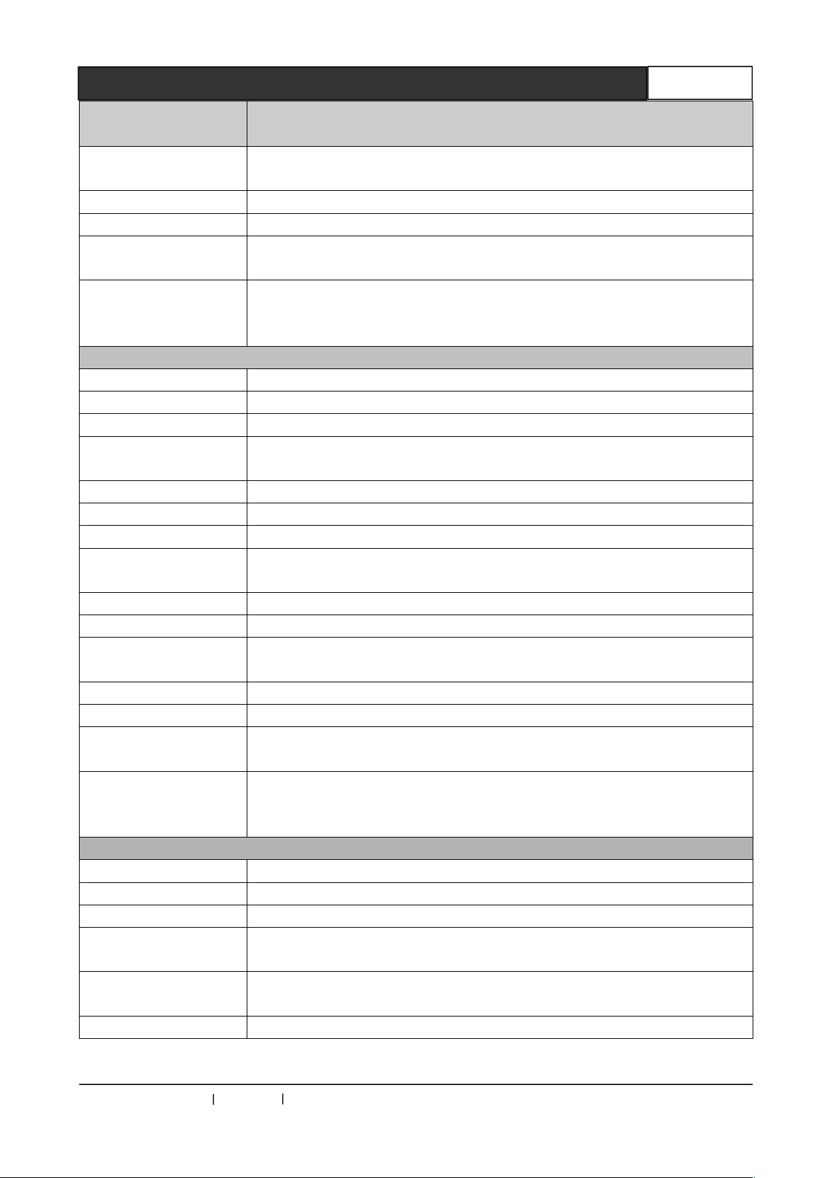
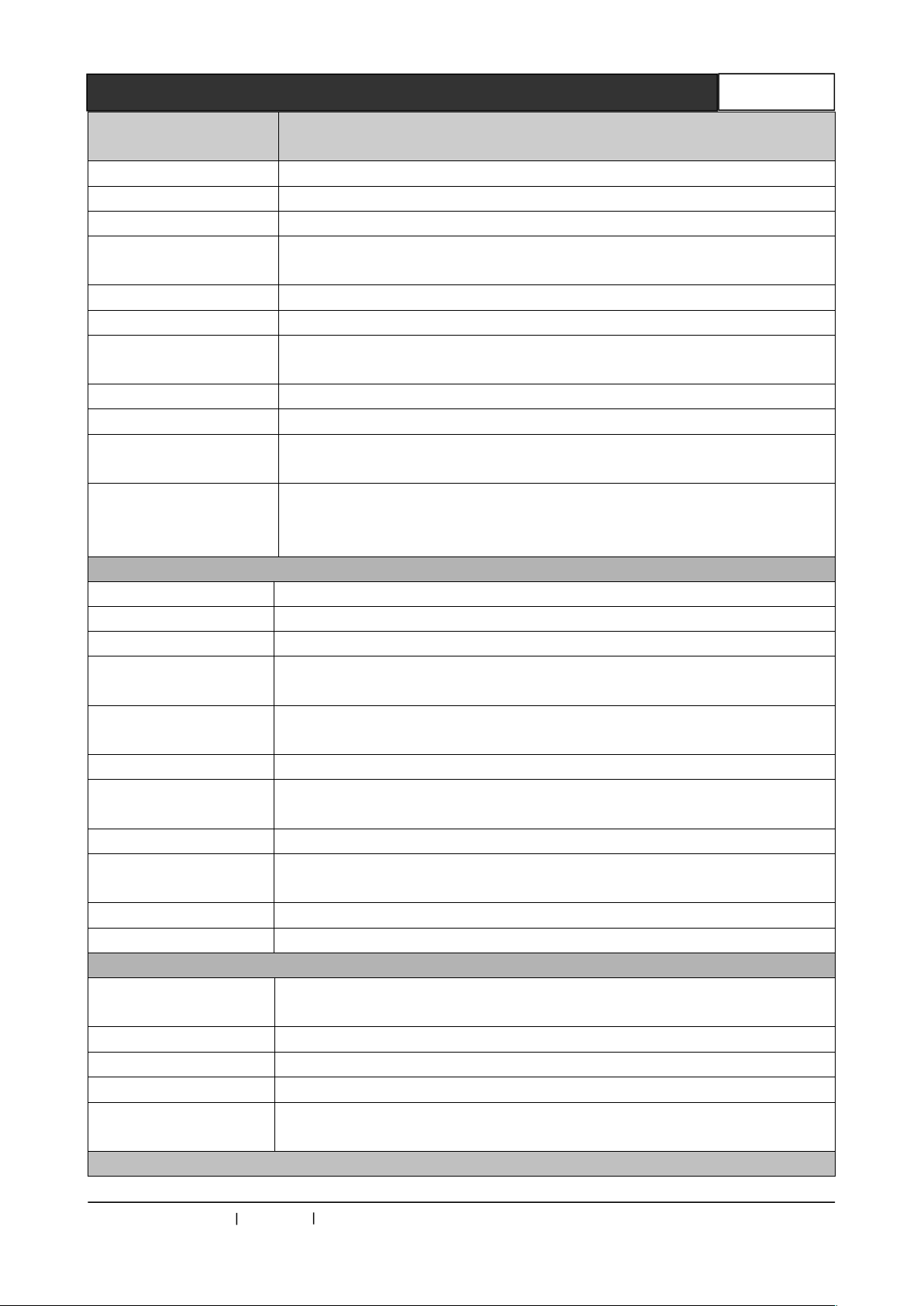
Specifications
Less than 10 meters, when the resolution is 1920x1080p@60
(recommended the use of certified HDMI special wire, as MoIex TM wire)
DVI-D/ HDMI full digital T.M.D.S. signal in DVI 1.0 / HDMI 1.3a
specification
Less than 10 meters, when the resolution is 1920x1080p@60
(recommended the use of certified HDMI special wire, as MoIex TM wire)
Model
CR-uSF AV 200T
Minimum / maximum
level
Input impedance 50 Ω
Input EDID Using the default EDID, (support terminal EDID mapping to input)
Maximum DC offset
error
The recommended
maximum input
distance
HDMI video input
Supported protocols DVI1.0,HDMI1.3a,HDCP1.3
PIXEL bandwidth The pixel bandwidth 165MHz , full digital
Interface bandwidth 2.25Gbps, full digital ( a total of 6.75Gbps. each color is 2.25Gbps )
Maximum support
resolution
Clock Jitter <0.15 Tbit
Rise time <0.3Tbit (20%--80%)
Fall time <0.3Tbit (20%--80%)
Signal Type
T.M.D.S. 2.9V/3.3V
+/-15mV
PC 1920x1200@60_24bit Color depth
HDTV 1920x1080P@60_36bit Color depth
Interface HDMI-A Interface (Type A connector )
Signal Strength T.M.D.S. 3.3V p-p
Minimum / maximum
level
Impedance 50 Ω
Input EDID Using the default EDID, (support terminal EDID mapping to input)
Maximum DC offset
error
The recommended
maximum input
distance
Sound signal
Input/output Interface 3.5mm unbalanced stereo audio input
Gain 0 dB
Frequency response 20 Hz ~ 20 kHz,
Total harmonic
distortion + noise
The signal-to-noise
ratio (S/N )
Stereo separation >80dB @ 1 kHz
T.M.D.S. 2.9V/3.3V
+/-15mV
0.01% @ 1 kHz (Under rated voltage)
>80dB at Vin=0 V
CREATOR CHINA 2013-08 WWW.CREATOR1997.COM
Page 16
Single Core Optical Fiber Transmitter User's Manual
11
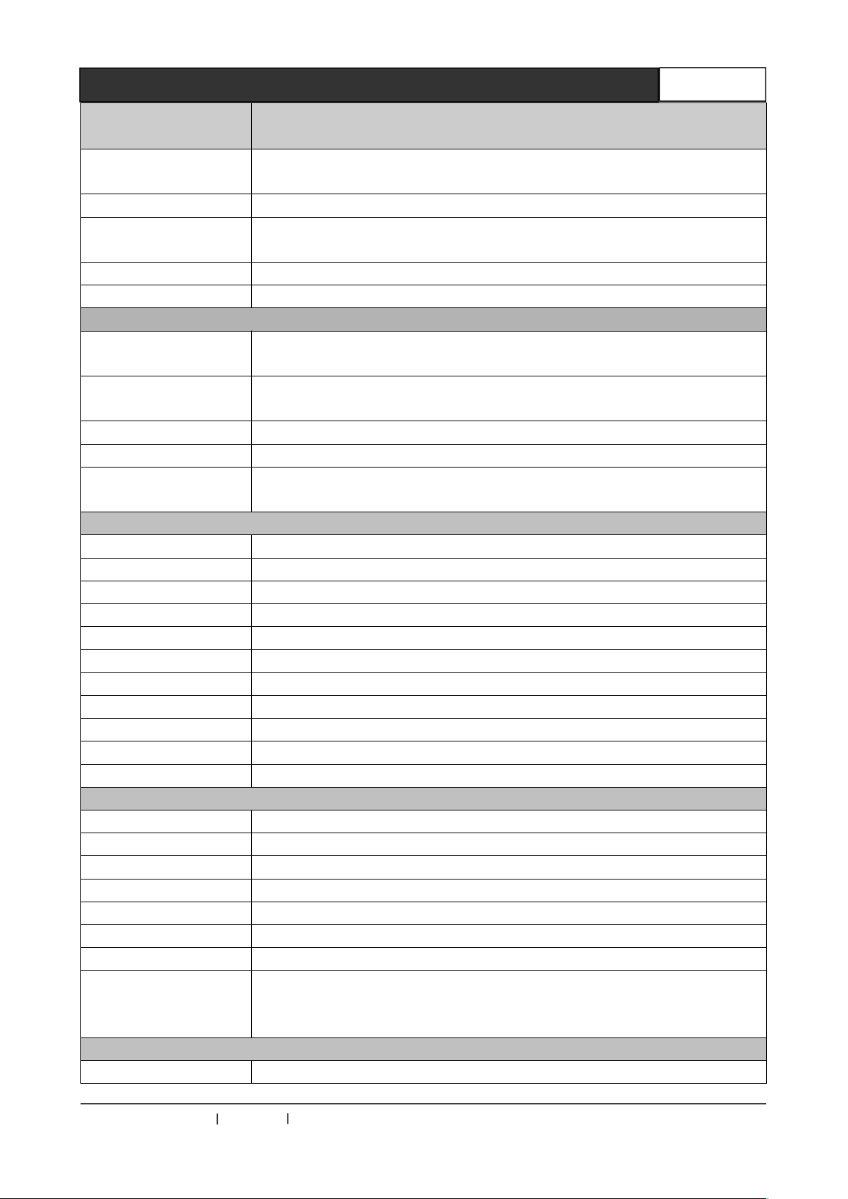
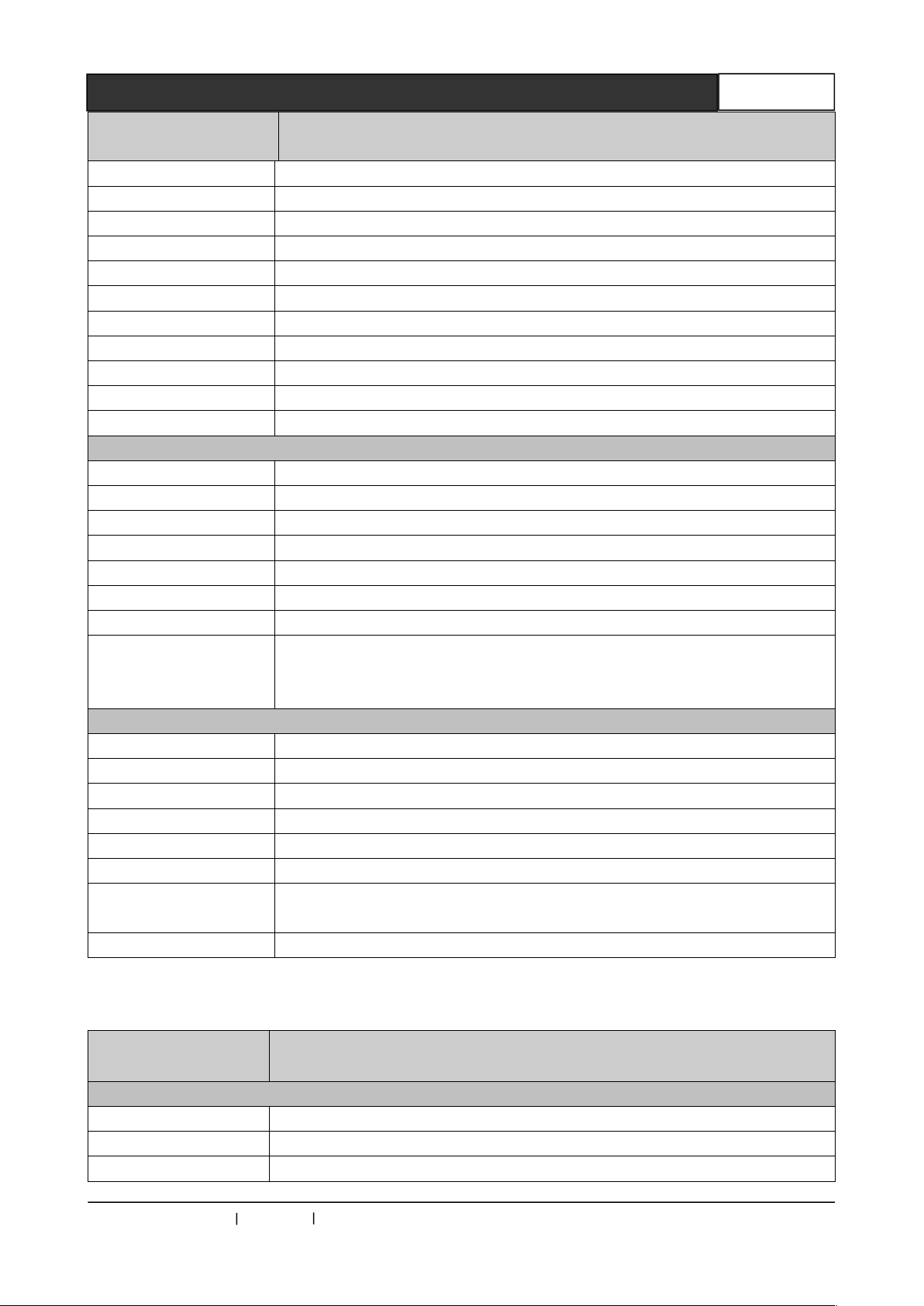
Specifications
OM3 multimode fiber; less than 300 meters, when the resolution is
1920x1080p@60
Model
CR-uSF AV 200T
Common mode
rejection ratio(CMRR)
Signal Type Stereo (Unbalanced connection)
Impedance
Maximum input level +19.5dBu, (balanced or unbalanced connection)
Gain error ±0.1dB @20 Hz ~ 20 kHz
IR INFRARED
Interface
Signal Type
Output level type PLL level
Wavelength 850nm
The carrier frequency
of input level
RS-232
Interface RS-232, 3.5mm unbalanced vertical stereo audio socket
Signal Type Digital
Level type RS-232 level
Signal direction Bi-direction communication
Baud rate Min;4800bps Max;115200bps
Data bits 8
Stop bit 1
Correction bits None
Flow control None
Level delay 500 ns
Peak +/-15V
Output
Fiber output interface SC connector
Fiber type Multimode / Single Mode(Optional)
Wavelength Multimode 850nm / Single Mode; 1310 –1620nm(Optional)
Interface bandwidth Positive; 6.25Gbps, reverse:3.125Gbps
Clock Jitter <0.15T bit
Rise time <0.3Tbit (20%--80%)
Fall time <0.3Tbit (20%--80%)
The recommended
maximum input
distance
Other specifications
Power supply Power adaptor,12VDC/2A
>75dB @; 20 Hz ~ 20 kHz
Input:>10 kΩ(balanced or unbalanced connection)
Output:50Ω ( unbalanced connection)
Input: 3.5mm unbalanced vertical stereo audio socket
Output:3.5mm unbalanced vertical stereo audio socket
Input; digital
Output; digital
38KHz
CREATOR CHINA 2013-08 WWW.CREATOR1997.COM
Page 17
Single Core Optical Fiber Transmitter User's Manual
12
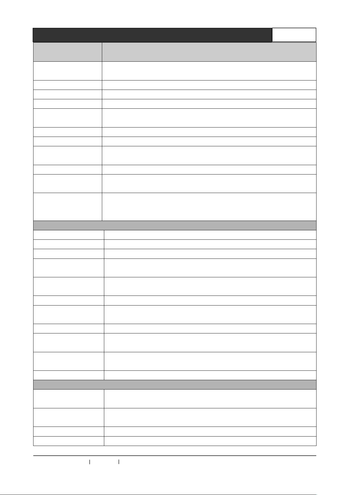
Specifications
Minimum / maximum
level
Model
Power consumption MAX 5W
Temperature Storage, use temperature; -20°~ +70°C
Humidity Storage, use humidity;10% ~90%
Dimension 162(L)X 155(W)X 35mm(H)
Weight 720g
Mean time between
failures
Warranty 1 year free warranty, life-long maintenance
30,000 hours
CR-uSF AV 200T
3.2 CR-uSF HD 200T Parameters
Specifications
Model
DVI video input
Supported protocols DVI1.0,HDMI1.3a,HDCP1.3
PIXEL bandwidth The pixel bandwidth165MHz , full digital
Interface bandwidth 2.25Gbps, full digital ( a total of 6.75Gbps. each color is 2.25Gbps )
Maximum support
resolution
Clock Jitter <0.15T bit
Rise time <0.3Tbit (20%--80%)
Fall time <0.3Tbit (20%--80%)
Signal Type DVI-D/ HDMI full digital T.M.D.S. signal in DVI 1.0 / HDMI 1.3a
Interface DVI-D Interface
Signal Strength T.M.D.S. 3.3V p-p
Input impedance 50 Ω
Input EDID Using the default EDID, (support terminal EDID mapping to input)
Maximum DC offset
error
The recommended
maximum input
distance
HDMI video input
Supported protocols DVI1.0,HDMI1.3a,HDCP1.3
PIXEL bandwidth The pixel bandwidth165MHz , full digital
Interface bandwidth 2.25Gbps, full digital ( a total of 6.75Gbps. each color is 2.25Gbps )
Maximum support
resolution
PC 1920x1200@60_24bit Color depth
HDTV 1920x1080P@60_36bit Color depth
specification
T.M.D.S. 2.9V/3.3V
+/-15mV
Less than 10 meters, when the resolution is 1920x1080p@60
(recommended the use of certified HDMI special wire, as MoIex TM wire)
PC 1920x1200@60_24bit Color depth
HDTV 1920x1080P@60_36bit Color depth
CR-uSF HD 200T
CREATOR CHINA 2013-08 WWW.CREATOR1997.COM
Page 18
Single Core Optical Fiber Transmitter User's Manual
13
Specifications
Minimum / maximum
level
Input: 3.5mm unbalanced vertical stereo audio socket / Output:3.5mm
unbalanced vertical stereo audio socket
Model
Clock Jitter <0.15T bit
Rise time <0.3Tbit (20%--80%)
Fall time <0.3Tbit (20%--80%)
Signal Type DVI-D/ HDMI full digital T.M.D.S. signal in DVI 1.0 / HDMI 1.3a
specification
Interface HDMI-A Interface
Signal Strength T.M.D.S. 3.3V p-p
T.M.D.S. 2.9V/3.3V
Impedance 50 Ω
Input EDID Using the default EDID, (support terminal EDID mapping to input)
Maximum DC offset
error
The recommended
maximum input
distance
Sound signal
Input / output interface 3.5mm unbalanced stereo audio input
Gain 0 dB
Frequency response 20 Hz ~ 20 kHz,
Total harmonic
distortion + noise
The signal-to-noise
ratio (S/N )
Stereo separation >80dB @ 1 kHz
Common mode
rejection ratio(CMRR)
Signal Type Stereo (Unbalanced connection)
Impedance
Maximum input level +19.5dBu, (Balanced or unbalanced connection)
Gain error ±0.1dB @20 Hz ~ 20 kHz
IR INFRARED
+/-15mV
Less than 10 meters, when the resolution is 1920x1080p@60
(recommended the use of certified HDMI special wire, as MoIex TM wire)
0.01% @ 1 kHz (Under rated voltage)
>80dB at Vin=0 V
>75dB @; 20 Hz ~ 20 kHz
Input:>10 kΩ(Balanced or unbalanced connection)
Output:50Ω ( unbalanced connection)
CR-uSF HD 200T
Interface
Signal Type Input; digital Output:digital
Output level type
Wavelength 850nm
The carrier frequency
of input level
RS-232
CREATOR CHINA 2013-08 WWW.CREATOR1997.COM
PLL level
38KHz
Page 19
Single Core Optical Fiber Transmitter User's Manual
14
Specifications
OM3 multimode fiber; less than 300 meters, when the resolution is
1920x1080p@60
Model
Interface RS-232, 3.5mm unbalanced vertical stereo audio socket
Signal Type digital
Level type RS-232 level
Signal direction Bi-direction communication
Baud rate Min;4800bps Max;115200bps
Data bits 8
Stop bit 1
Correction bits None
Flow control None
Level delay 500 ns
Peak +/-15V
Output
Fiber output interface SC connector
Fiber type Multimode / Single Mode(Optional)
Wavelength Multimode 850nm / Single Mode; 1310 –1620nm(Optional)
Interface bandwidth Positive; 6.25Gbps, reverse:3.125Gbps
Clock Jitter <0.15Tbit
Rise time <0.3Tbit (20%--80%)
Fall time <0.3Tbit (20%--80%)
The recommended
maximum input
distance
Other specifications
Power supply Power adaptor,12VDC/2A
Power consumption MAX 5W
Temperature Storage, use temperature; -20°~ +70°C
Humidity Storage, use humidity;10% ~90%
Dimension 162(L)X 155(W)X 35mm(H)
Weight 620g
Mean time between
failures
Warranty 1 year free warranty, life-long maintenance
30,000 hours
CR-uSF HD 200T
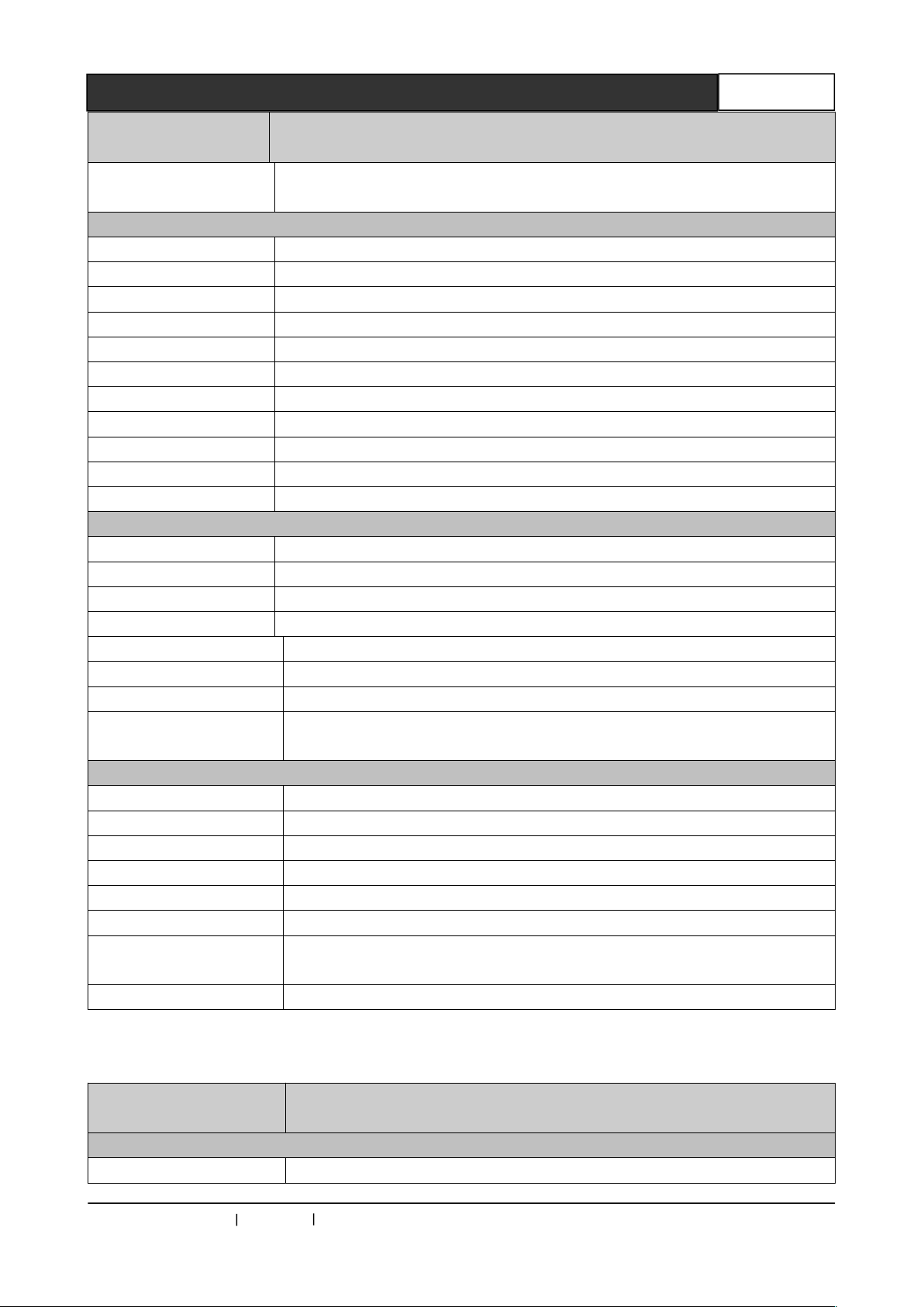
3.3 CR-uSF DVI 200R Parameters
Specifications
Model
DVI video output
Supported protocols DVI1.0, HDMI1.3a, HDCP1.3
PIXEL bandwidth The pixel bandwidth 165MHz , full digital
Interface bandwidth 2.25Gbps, full digital ( a total of 6.75Gbps. each color is 2.25Gbps )
CREATOR CHINA 2013-08 WWW.CREATOR1997.COM
CR-uSF DVI 200R
Page 20
Single Core Optical Fiber Transmitter User's Manual
15
Specifications
Maximum support
resolution
The maximum output
level
Model
PC 1920x1200@60_24bit Color depth
HDTV 1920x1080P@60_36bit Color depth
Clock Jitter <0.15Tbit
Rise time <0.3Tbit (20%--80%)
Fall time <0.3Tbit (20%--80%)
Signal Type DVI-D/ HDMI full digital T.M.D.S. signal in DVI 1.0 / HDMI 1.3a
specification
Interface DVI-D Interface
Signal Strength T.M.D.S. 3.3V p-p
Minimum / maximum
level
Output impedance 50 Ω
Maximum DC offset
error
The recommended
maximum output
distance
Sound signal
Input interface 3.5mm unbalanced stereo audio input
Gain 0 dB
Frequency response 20 Hz ~ 20 kHz,
Total harmonic
distortion + noise
The signal-to-noise
ratio (S/N )
Stereo separation >80dB @ 1 kHz
Common mode
rejection ratio(CMRR)
Signal Type Stereo (Unbalanced connection)
Impedance
T.M.D.S. 2.9V/3.3V
+/-15mV
Less than 10 meters, when the resolution is 1920x1080p@60
(recommended the use of certified HDMI special wire, as MoIex TM wire)
0.01% @ 1 kHz (Under rated voltage)
>80dB at Vin=0 V
>75dB @; 20 Hz ~ 20 kHz
Input:>10 kΩ(Balanced or unbalanced connection)
Output:50Ω ( unbalanced connection)
CR-uSF DVI 200R
+19.5dBu, (Balanced or unbalanced connection)
Gain error ±0.1dB @20 Hz ~ 20 kHz
IR INFRARED
Interface
Signal Type
Output level type
Wavelength 850nm
CREATOR CHINA 2013-08 WWW.CREATOR1997.COM
Input;: 3.5mm unbalanced vertical stereo audio socket
Output:3.5mm unbalanced vertical stereo audio socket
Input; digital
Output:digital
PLL level
Page 21
Single Core Optical Fiber Transmitter User's Manual
16
Specifications
The recommended
maximum input distance
OM3 multimode fiber; less than 300 meters, when the resolution is
1920x1080p@60
Model
CR-uSF DVI 200R
The carrier frequency
of input level
RS-232
Interface RS-232, 3.5mm unbalanced vertical stereo audio socket
Signal Type digital
Level type RS-232 level
Signal direction Bi-direction communication
Baud rate Min;4800bps Max;115200bps
Data bits 8
Stop bit 1
Correction bits None
Flow control None
Level delay 500 ns
Peak +/-15V
Input
Fiber output interface SC connector
Fiber type Multimode / Single Mode(Optional)
Wavelength Multimode; 850nm / Single Mode; 1310 –1620nm(Optional)
Interface bandwidth Positive; 6.25Gbps, reverse:3.125Gbps
Clock Jitter <0.15T bit
Rise time <0.3Tbit (20%--80%)
Fall time <0.3Tbit (20%--80%)
38KHz
Other specifications
Power supply Power adaptor,12VDC/2A
Power consumption MAX 5W
Temperature Storage, use temperature; -20°~ +70°C
Humidity Storage, use humidity;10% ~90%
Dimension 162(L)X 155(W)X 35mm(H)
Weight 600g
Mean time between
failures
Warranty 1 year free warranty, life-long maintenance
30,000 hours
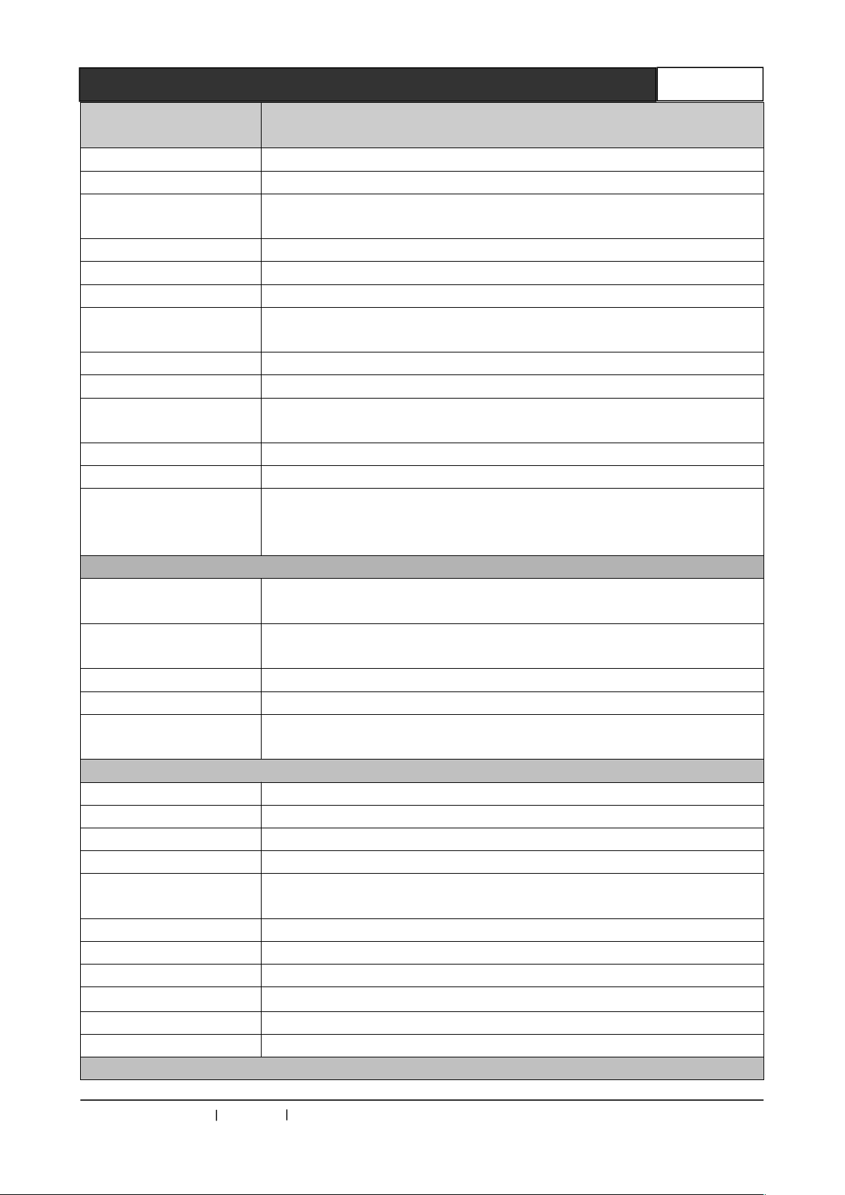
3.4 CR-uSF HDMI 200R Parameters
Specifications
Model
HDMI video output
Supported protocols DVI1.0, HDMI1.3a, HDCP1.3
CREATOR CHINA 2013-08 WWW.CREATOR1997.COM
CR-uSF HDMI 200R
Page 22
Single Core Optical Fiber Transmitter User's Manual
17
Specifications
DVI-D/ HDMI full digital T.M.D.S. signal in DVI 1.0 / HDMI 1.3a
specification
Maximum DC offset error
Model
PIXEL bandwidth The pixel bandwidth 165MHz , full digital
Interface bandwidth 2.25Gbps, full digital ( a total of 6.75Gbps. each color is 2.25Gbps )
Maximum support
resolution
Clock Jitter <0.15Tbit
Rise time <0.3Tbit (20%--80%)
Fall time <0.3Tbit (20%--80%)
Signal Type
Interface HDMI-A Interface
Signal Strength T.M.D.S. 3.3V p-p
Minimum / maximum
level
Impedance 50 Ω
The recommended
maximum output
distance
IR INFRARED
Interface
Signal Type
Output level type
Wavelength 850nm
The carrier frequency of
input level
RS-232
Interface RS-232, 3.5mm unbalanced vertical stereo audio socket
Signal Type Digital
Level type RS-232 level
Signal direction Bi-direction communication
Baud rate
Data bits 8
Stop bit 1
Correction bits None
Flow control
Level delay 500 ns
Peak +/-15V
Input
PC 1920x1200@60_24bit Color depth
HDTV 1920x1080P@60_36bit Color depth
T.M.D.S. 2.9V/3.3V
+/-15mV
Less than 10 meters, when the resolution is 1920x1080p@60
(recommended the use of certified HDMI special wire, as MoIex TM wire)
Input: 3.5mm unbalanced vertical stereo audio socket
Output:3.5mm unbalanced vertical stereo audio socket
Input; digital
Output:digital
PLL level
38KHz
Min;4800bps
Max;115200bps
None
CR-uSF HDMI 200R
CREATOR CHINA 2013-08 WWW.CREATOR1997.COM
Page 23
Single Core Optical Fiber Transmitter User's Manual
18
Specifications
Mean time between
failures
Maximum rise / fall time
Model
Fiber output interface SC connector
Fiber type Multimode / Single Mode(Optional)
Wavelength Multimode; 850nm / Single Mode; 1310 –1620nm(Optional)
Interface bandwidth Positive; 6.25Gbps, reverse:3.125Gbps
Clock Jitter <0.15T bit
Rise time <0.3Tbit (20%--80%)
Fall time <0.3Tbit (20%--80%)
OM3 multimode fiber; less than 300 meters,when the resolution is
The recommended
maximum input distance
Other specifications
Power supply Power adaptor,12VDC/2A
Power consumption MAX 5W
Temperature Storage, use temperature; -20°~ +70°C
Humidity Storage, use humidity;10% ~90%
Dimension 162(L)X 155(W)X 35mm(H)
Weight 600g
1920x1080p@60
Single-mode fiber; less than 10km,when the resolution is
1920x1080p@60
CR-uSF HDMI 200R
30,000 hours
Warranty 1 year free warranty, life-long maintenance
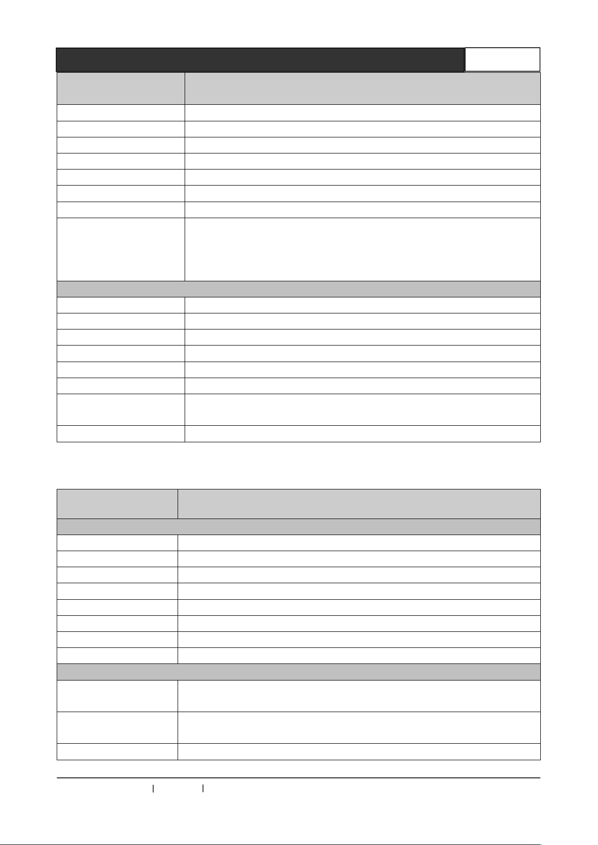
3.5 CR-uSF VGA 200R Parameters
Specifications
Model
VGA video output
Gain 0 dB
Bandwidth 380 MHz
Signal Type VGA
Interface 15-pinDB female interface
Signal Strength 0.7V p-p
Impedance 75 Ω
Echo Loss <-30dB@5MHz
DC compensation Maximum ±5mV
VGA synchronous signal
Input/output Signal
Type
Maximum transmission
delay
RGBHV, RGBS, RGsB , RsGsBs,
Horizontal;90ns Vertical;160ns
4ns
CR-uSF VGA 200R
CREATOR CHINA 2013-08 WWW.CREATOR1997.COM
Page 24
Single Core Optical Fiber Transmitter User's Manual
19
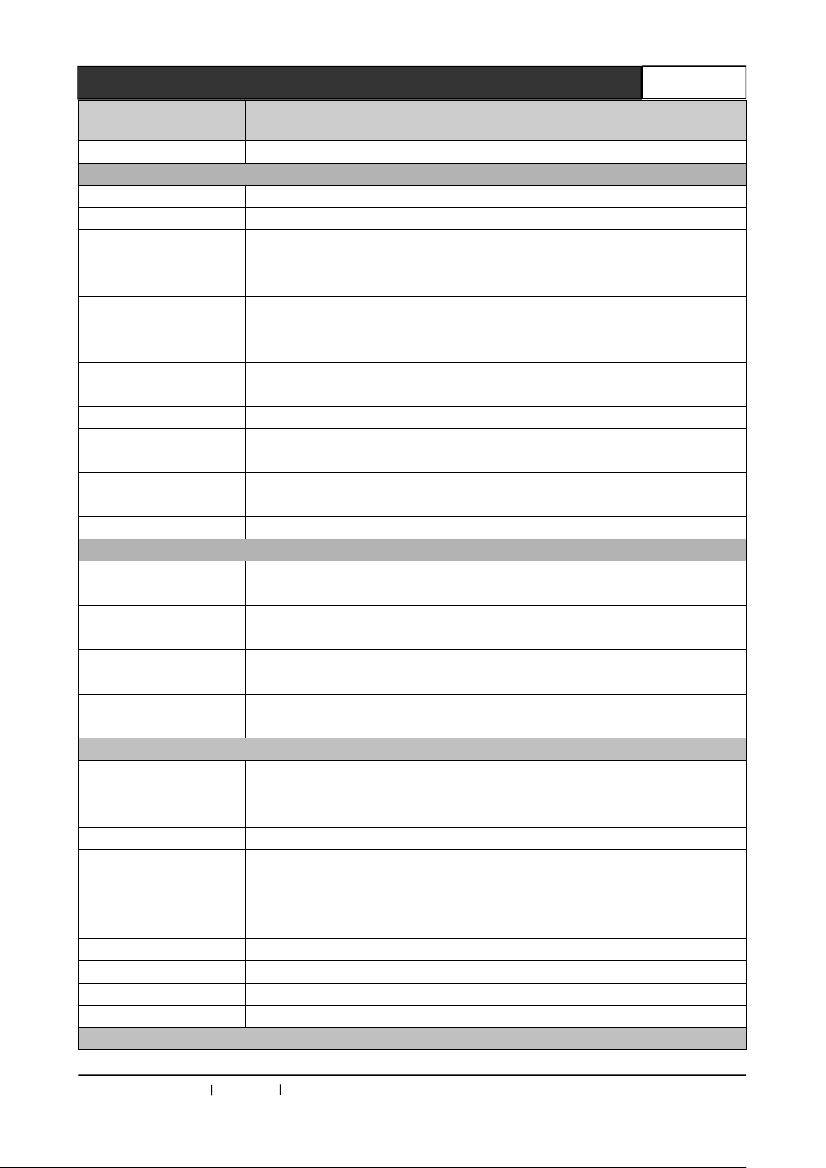
Specifications
The maximum output
level
Model
Polarity Positive or negative (completely consistent with the input)
Sound signal
Input interface 3.5mm unbalanced stereo audio input
Gain 0 dB
Frequency response 20 Hz ~ 20 kHz,
Total harmonic
distortion + noise
The signal-to-noise
ratio (S/N)
Stereo separation >80dB @ 1 kHz
Common mode
rejection ratio(CMRR)
Signal Type Stereo (unbalanced connection)
Impedance
0.01% @ 1 kHz (Under rated voltage)
>80dB at Vin=0 V
>75dB @; 20 Hz ~ 20 kHz
Input:>10 kΩ(balanced or unbalanced connection)
Output:50Ω ( unbalanced connection)
+19.5dBu, (Balanced or unbalanced connection)
CR-uSF VGA 200R
Gain error ±0.1dB @20 Hz ~ 20 kHz
IR INFRARED
Interface
Signal Type
Output level type
Wavelength 850nm
The carrier frequency
of input level
RS-232
Interface RS-232, 3.5mm unbalanced vertical stereo audio socket
Signal Type Digital
Level type RS-232 level
Signal direction Bi-direction communication
Baud rate
Data bits 8
Stop bit 1
Correction bits None
Flow control None
Level delay 500 ns
Peak +/-15V
Input
Input: 3.5mm unbalanced vertical stereo audio socket
Output:3.5mm unbalanced vertical stereo audio socket
Input; digital
Output:digital
PLL level
38KHz
Min; 4800bps
Max;115200bps
CREATOR CHINA 2013-08 WWW.CREATOR1997.COM
Page 25
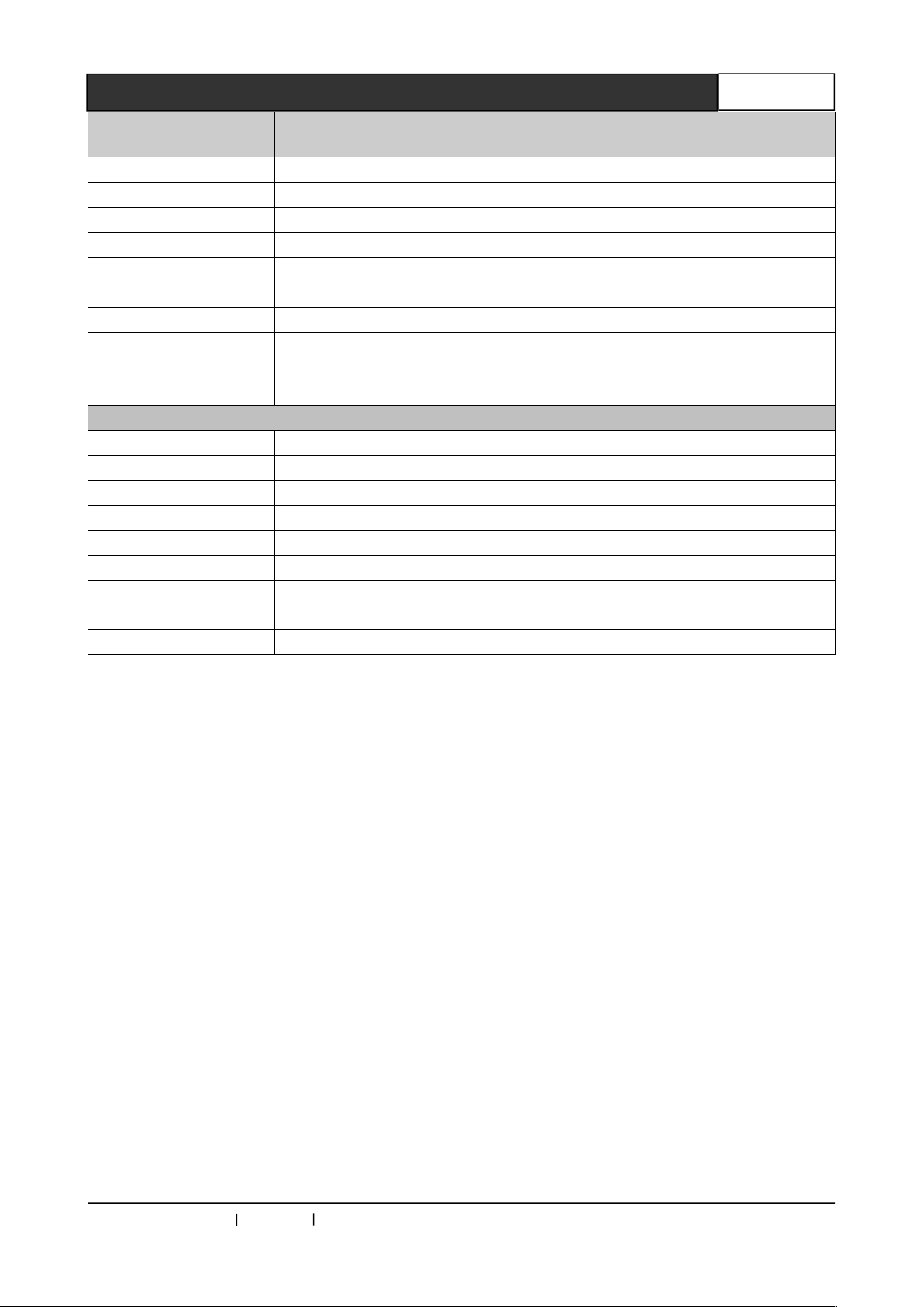
Single Core Optical Fiber Transmitter User's Manual
20
Specifications
OM3 multimode fiber; less than 300 meters, when the resolution is
1920x1080p@60
Model
Fiber output interface SC connector
Fiber type Multimode / Single Mode(Optional)
Wavelength Multimode; 850nm / Single Mode; 1310 –1620nm(Optional)
Interface bandwidth Positive; 6.25Gbps, reverse:3.125Gbps
Clock Jitter <0.15T bit
Rise time <0.3Tbit (20%--80%)
Fall time <0.3Tbit (20%--80%)
The recommended
maximum input
distance
Other specifications
Power supply Power adaptor,12VDC/2A
Power consumption MAX 5W
Temperature Storage, use temperature; -20°~ +70°C
Humidity Storage, use humidity;10% ~90%
Dimension 162(L)X 155(W)X 35mm(H)
Weight 600g
Mean time between
failures
Warranty 1 year free warranty, life-long maintenance
30000 hours
CR-uSF VGA 200R
CREATOR CHINA 2013-08 WWW.CREATOR1997.COM
Page 26
Single Core Optical Fiber Transmitter User's Manual
21
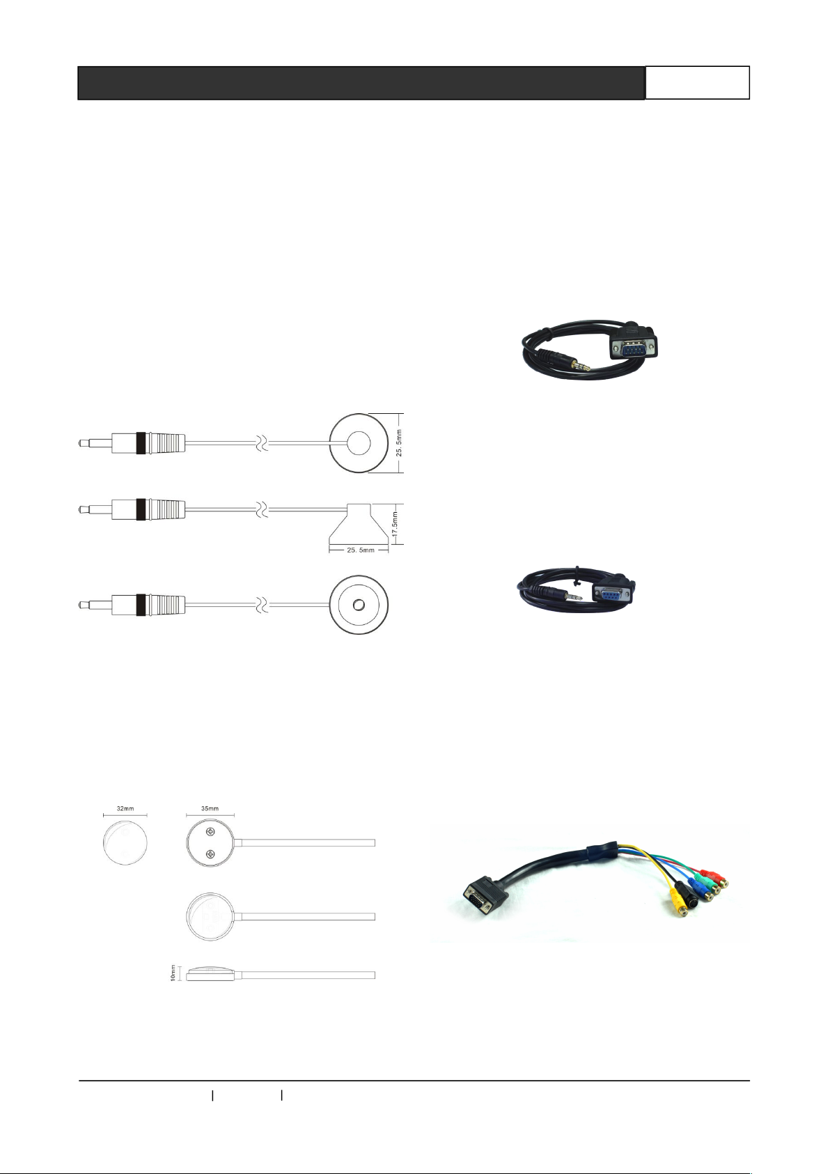
Chapter 4 Accessories
4.1 Infrared Transmitter
CR-IR/T
The infrared transmitter CR-IR / T is used to
transmit infrared signals to the infrared receiver,
infrared emission frequency ranging from 20 KHz
to 100KHz.
CR-IR/T
Dimensions;
4.2 Infrared Receiver CR-IR/R
Infrared receiver CR-IR / R is for receiving
the infrared signal to the infrared device, infrared
receiver frequency is38KHz.
CR-IR/R Dimensions:
4.3 3.5mm Headset Connector
to DB9 Male Socket Connecting
Line
4.4 3.5mm Headset Connector
to DB9 Female Socket
Connecting Line
4.5 DB15 Male Socket to RCA
Terminal, SV Terminal
Connection Line (VGA to CV
video, Y/C video, YPbPr video)
CREATOR CHINA 2013-08 WWW.CREATOR1997.COM
Page 27

CREATOR CORPORATION(CHINA)
Copyright by CREATOR
Last Revision:08/2013
 Loading...