

Page 1

SPECIFICATION
Model No.
Date
CRT-603-DB1
2012/11/24
User Manual
File Ver . 1.0
Page 1/48
User Manual
(V1.0.0.2)
CREATOR (CHINA) TECH CO., LTD
ADD: 2/F, M-10 Building, Center Area, High-tech Industrial Park
Shenzhen, Guangdong, China.
Tel: +86-755-26710345
Fax: +86-755-26710105
EMAIL: [email protected]
Http://www.china-creator.com
Page 2
SPECIFICATION
Model No.
Date
CRT-603-DB1
2012/11/24
User Manual
File Ver . 1.0
Page 2/48
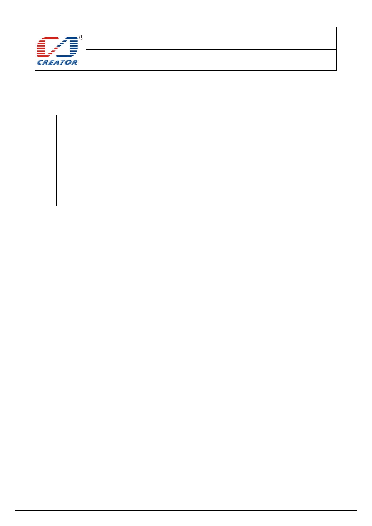
Version Date Note
1.0.0.0 2012.12.20 First release
Add more than one card of TYPEB identified function
1.0.0.1 2013.08.20
1.0.0.2 2013.12.24
Add more than one card of TYPEA and TYPEB identified
function
add functions of mode set for checking collision
and inquiring status to support TYPEA&TYPEB
cards
Page 3

SPECIFICATION
Model No.
Date
CRT-603-DB1
2012/11/24
User Manual
File Ver . 1.0
Page 3/48
Firmware Version
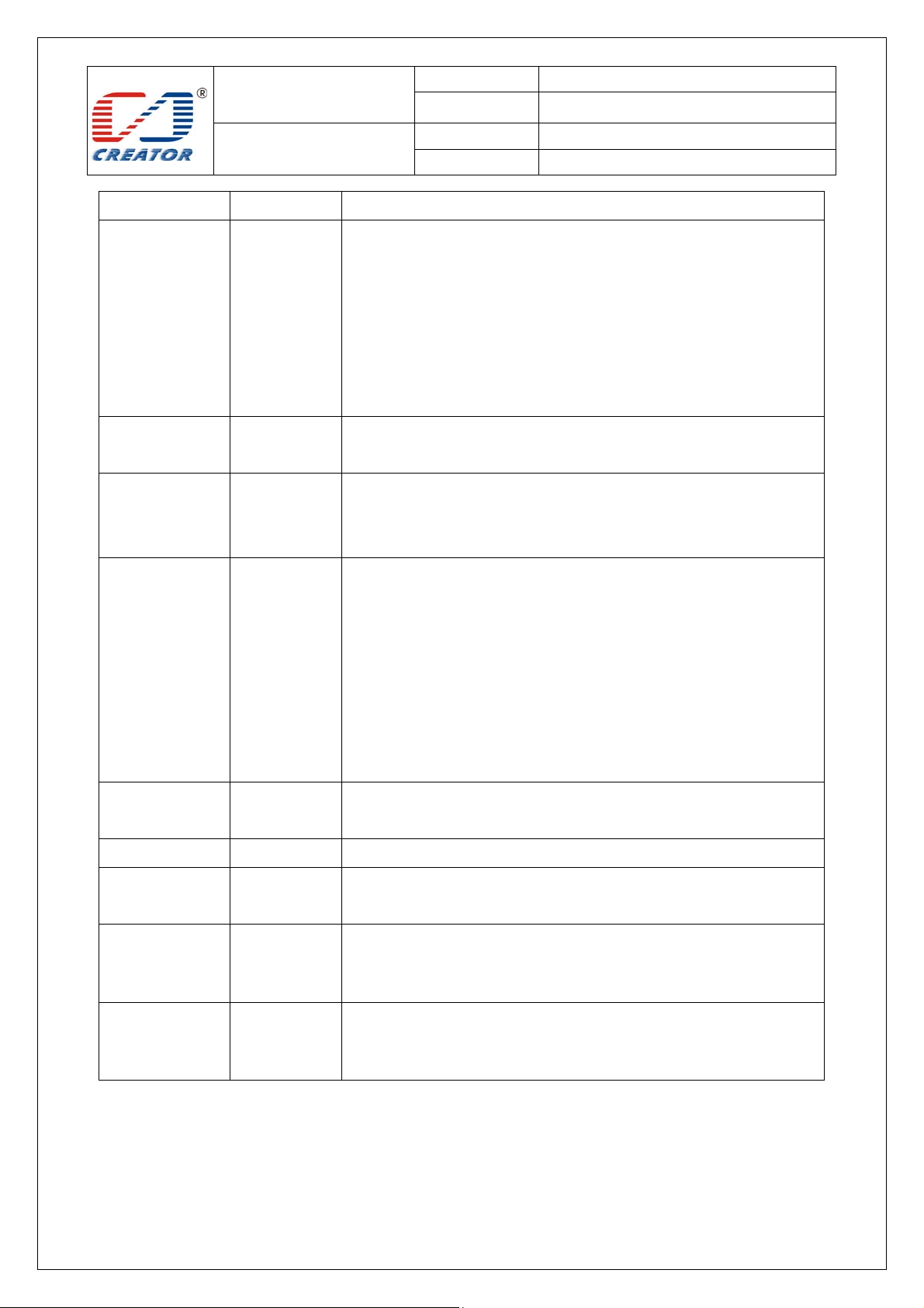
Version Date Note
1.0.0.0 2012.12.20 First release
Replacement of card slot changing, lamp control, buzzer set and
control, SAM card board and SAM card slot detection, write
1.0.0.1 20120718
EEPROM, read EEPROM, write P/N, read P/N, write Serial Number,
read Serial Number, write Vendor MFG Date, read Vendor MFG Date,
write Vendor MFG P/F , write Vendor MFG P/F command, revise FW
version format.
Add new extend instruction protocol,
LED mode changing instruction, LED mode inquiry instruction, LED
1.0.0.2 20120810
1.0.0.3 20120903
1.0.0.4 20120924
host control instruction and inquiry instruction.
Diebold MFG Date read & write instruction, Diebold MFG P/F read &
write instruction
revise FW version format
Changing single reader mode into dual readers mode
Testing aim to function of hardware, PCSC, RF card library, SAM card
library and extend
Add 70 ℃ -- 20℃ test
Clear up blue lamp status when card collision occurs
Add lamp inquiry function under CCR lamp automation control
LED lamp indicates only in successful connection
Buzzer responses only in successful connection
Clear up error status of card slot changing operation with card in SAM
card slot (report card moving out)
SAM reader reports card information only in successful changing
APDU control LED lamp and buzzer
Deactive card, green lamp will be on when the reader is standing by
1.0.0.5 20121016
Download identification key of mifare one card to ROM, actually save
it into EEPROM in RF IC (Key No. is 1)
Once contactless CPU card is actived, it will be not done again in its
middle stage, support break operation.
Once S50/S70 card key is verified, it will be not actived again in its
Page 4
SPECIFICATION
Model No.
Date
CRT-603-DB1
2012/11/24
User Manual
1.0.0.6 20121023
1.0.0.7 20121030
1.0.0.8 20121107
File Ver . 1.0
Page 4/48
middle stage, support break operation
When SAM card reader executes command for card slot changing,
prior to change slot, then reports information of card inserting and
pulling, finally executes return command
APDU is of EEPROM operation, reboot, gain FW version, skip to IAP
mode
After RF actived, keep the state and prevent interfering from another
RF card
Fail to modify RF verifying password without changing card state, go
on verfying password untill success to read data
Add automatically green lamp on function(if red lamp on, green lamp
off)
optimize the judgement of "connect reader" operation
Clear up the appearance of reader halted when reader feed back some
RF length data
Clear up the appearance of reader halted when reader feed back some
SAM card length data
1.0.0.9 20121113
Clear up the error of unable to send special APDU command to RF
reader in V1.0.0.8
Clear up the error of unable to send any command to RF reader in
V1.0.0.8
support Shang Hai commute system operation
1.0.1.0 20121121
Clear up return empty information bug
1.0.1.1 20130613 close led lamp PWM control function
1.0.1.2 20130708
Add more than one card of TYPEB identified function
Add more than one card of TYPEA and TYPEB identified function
1. Improve SPI data transmit function and RF data transmit and
1.0.1.3 20131213
receiving function, both functions add timing close
2. Improve the configure information of ISO14443-4 SFGI
add functions of mode set for checking collision and inquiring
1.0.1.4 20131224
status to support TYPEA&TYPEB cards
Page 5

SPECIFICATION
Model No.
Date
CRT-603-DB1
2012/11/24
User Manual
File Ver . 1.0
Page 5/48
CONTENT
1 Overview ................................................................................................................................................................ 7
1.1 Product Description ..................................................................................................................................... 7
1.2 Features ........................................................................................................................................................ 7
1.3 USB Interface .............................................................................................................................................. 7
2 Product Hardware ................................................................................................................................................... 8
2.1 Product components ..................................................................................................................................... 8
Note: ②SAM card board is an optional choice for customerImages of boards ............................................... 8
Images of boards ................................................................................................................................................ 9
2.2 Reader function ........................................................................................................................................... 11
2.2.1 Contactless Card interface function ................................................................................................. 11
2.2.2 SAM card reader interface function: ................................................................................................ 11
3 Card Operation ..................................................................................................................................................... 12
3.1 Contact Card Environment Specifics ......................................................................................................... 12
3.1.1 ATR of SAM Card .......................................................................................................................... 12
3.1.2 APDU Command of SAM Card ..................................................................................................... 12
3.2 Contactless Card Environment Specifics ................................................................................................... 13
3.2.1 ATR of Contactless Card ................................................................................................................. 13
3.2.2 APDU Command of Contactless Card ............................................................................................ 15
4 Extended Command (Extended Capabilities) ....................................................................................................... 20
4.1 Extended Command Brief Introduction ..................................................................................................... 20
4.2 Extended Command Detail Description .................................................................................................... 21
4.2.1 Choose SAM Card Slot................................................................................................................... 21
4.2.2 Get SAM card board and SAM slot status ...................................................................................... 22
4.2.3 LED Control Rules ......................................................................................................................... 23
4.2.4 Set LED Working Mode ................................................................................................................. 24
4.2.5 Get LED Working Mode ................................................................................................................. 25
4.2.6 HOST Set LED Status .................................................................................................................... 26
4.2.7 Get LED status ................................................................................................................................ 28
4.2.8 Enable/Disable Buzzer Beep .......................................................................................................... 29
4.2.9 Control Buzzer Beep ....................................................................................................................... 30
4.2.10 Pre-set data layout of card reader EEPROM ................................................................................ 31
4.2.11 W r ite EEPROM ............................................................................................................................ 32
4.2.12 Read EEPROM ............................................................................................................................. 33
4.2.13 Write P/N ...................................................................................................................................... 34
4.2.14 Read P/N ....................................................................................................................................... 35
4.2.15 Write Serial Number ..................................................................................................................... 36
4.2.16 Read Serial Number ...................................................................................................................... 37
4.2.17 Write Vendor MFG Date ............................................................................................................... 38
4.2.18 Read Vendor MFG Date ............................................................................................................... 39
4.2.19 Write Vendor MFG P/F ...................................................................................................
4.2.20 Read Vendor MFG P/F ................................................................................................................. 41
4.2.21 Write Diebold MFG Date ............................................................................................................. 42
4.2.22 Read Diebold MFG Date .............................................................................................................. 43
4.2.23 Write Diebold MFG P/F ............................................................................................................... 44
4.2.24 Read Diebold MFG P/F ................................................................................................................ 45
4.2.25 Get Firmware Version ................................................................................................................... 46
4.2.26 Restart Reader ............................................................................................................................... 47
.............. 40
Page 6
SPECIFICATION
Model No.
Date
CRT-603-DB1
2012/11/24
User Manual
File Ver . 1.0
Page 6/48
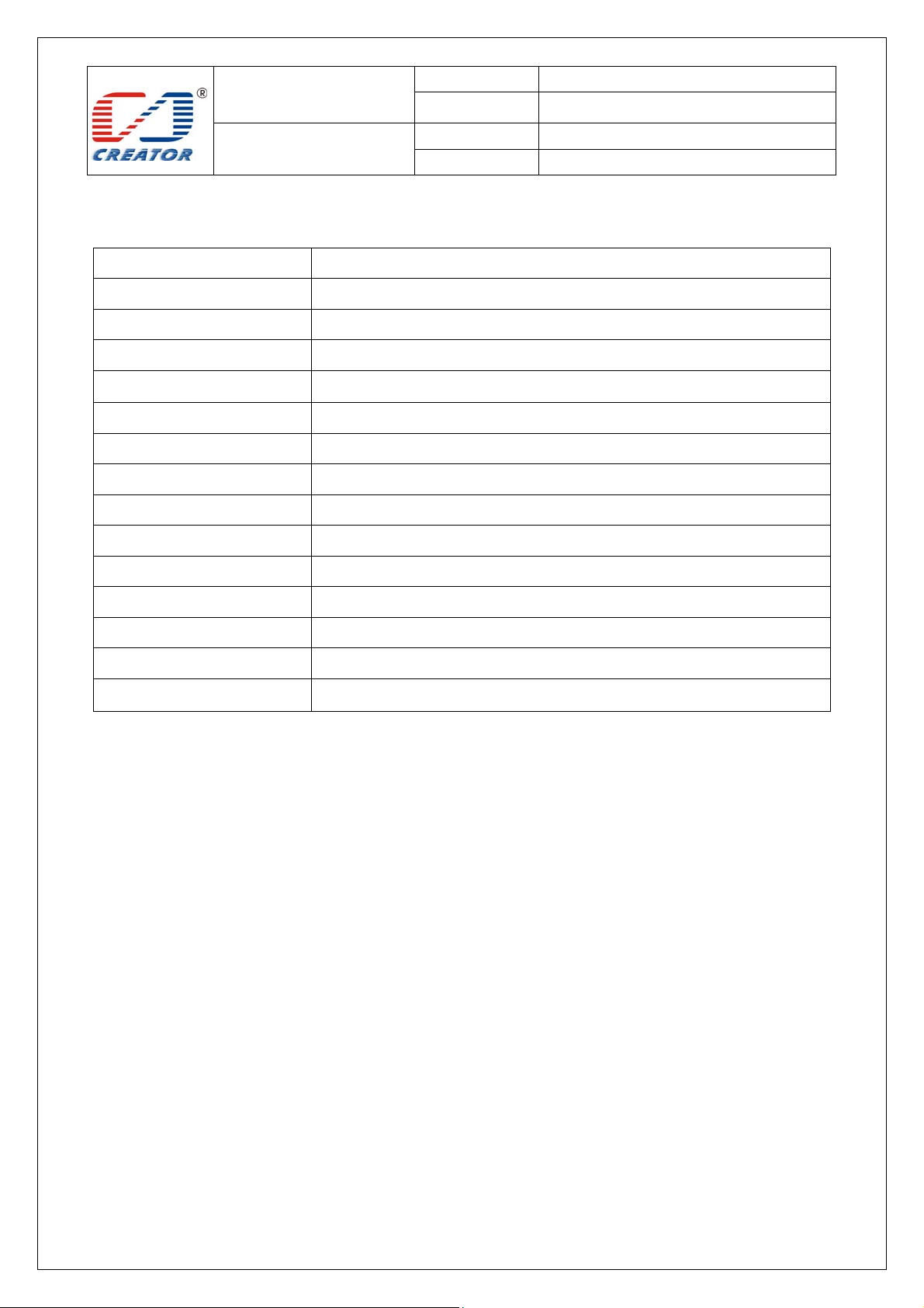
Glossary
Acronym/Abbreviation Expansion
APDU Application Protocol Data Unit
ATR Answer to Reset, defined in ISO7816
ATS Answer to select, defined in ISO/IEC 14443
CCID Chip Card Interface Device
CID Card Identifier
CL Contact-Less
FWT Frame Waiting Time
Mifare The ISO14443 with extensions for security (PHILIPS)
NAD Node Address
PCD Proximity Coupling Device
PCSC Personal computer Smart card
PICC Proximity Integrated Chip Card
RF Radio Frequency
USB Universal Serial Bus
Page 7
SPECIFICATION
Model No.
Date
CRT-603-DB1
2012/11/24
User Manual
File Ver . 1.0
Page 7/48
1 Overview
1.1 Product Description
CRT-603 is a USB dual interface card reader running on Windows including contactless card interface and SAM
card interface. The reader complies with PC/SC standard, ISO14443 standard applicable to type A and type B
contactless cards and ISO14443-3 standard applicable to MIFARE series contactless cards. It also complies with
ISO7816 standard related to SAM card.
1.2 Features
¾ Bus powered, USB 2.0 full speed
¾ PC/SC V2.0 compliant, CCID interface, support Windows XP and Windows 7
¾ Contactless card interface, antenna and main board separated design
¾ SAM card reader interface, User can select one of the 4 SAM slot of the SAM card reader interface to
operate
¾ Automatically search contactless card and handle anti-collision for more than one card
¾ Support ISO14443-4 type A&B contactless cards
¾ Support ISO14443-3 S50,S70 and UL etc contactless Storage Card
¾ Support ISO7816 SAM card
¾ 100 bytes EEPROM available for user to store permanent data
¾ Firmware online update through USB ( supplier IAP tool provided )
¾ DC 5V, static current 200mA, dynamic current 220mA, peak current 250mA
¾ EMC, QPBOC certified
1.3 USB Interface
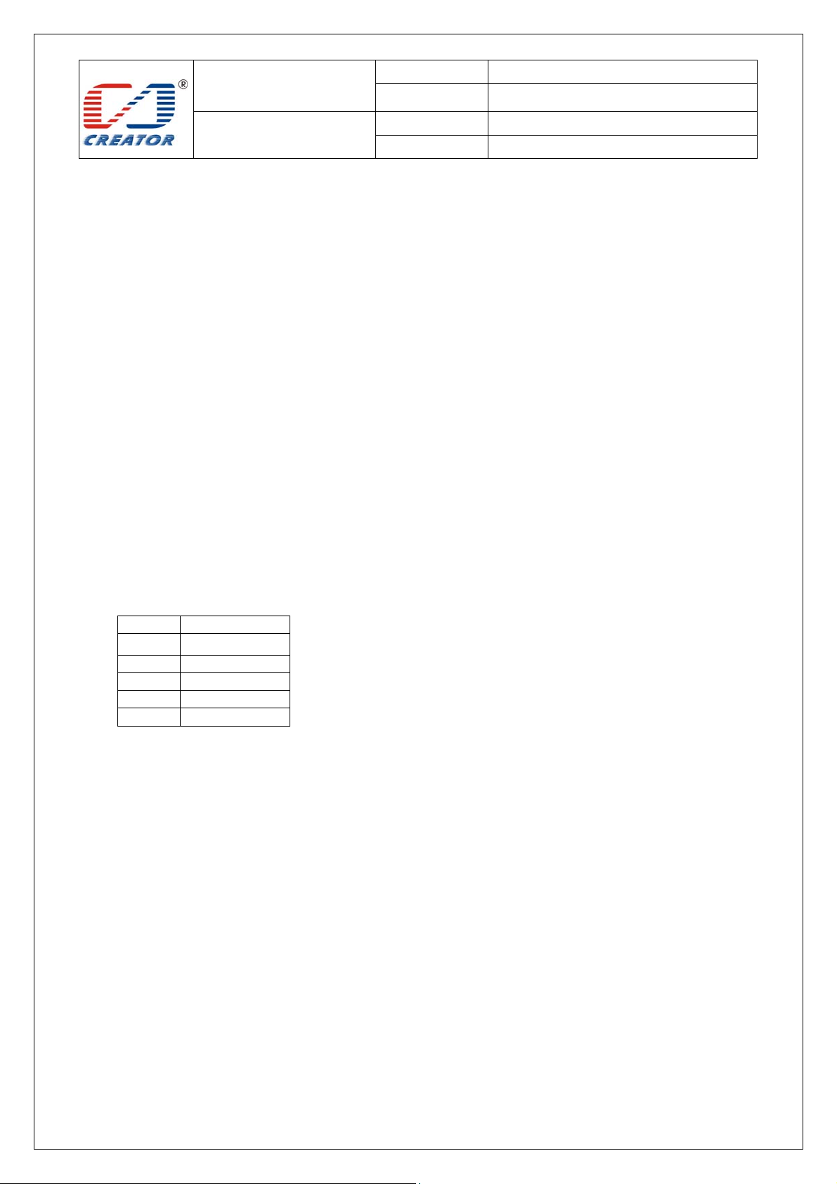
Card reader is connected to the host with a mini USB cable, PIN definition is as following:
PIN Signal
1 VBUS
2 D3 D+
4 ID
5 GND
Page 8
SPECIFICATION
Model No.
Date
CRT-603-DB1
2012/11/24
2 Product Hardware
2.1 Product components
User Manual
File Ver . 1.0
Page 8/48
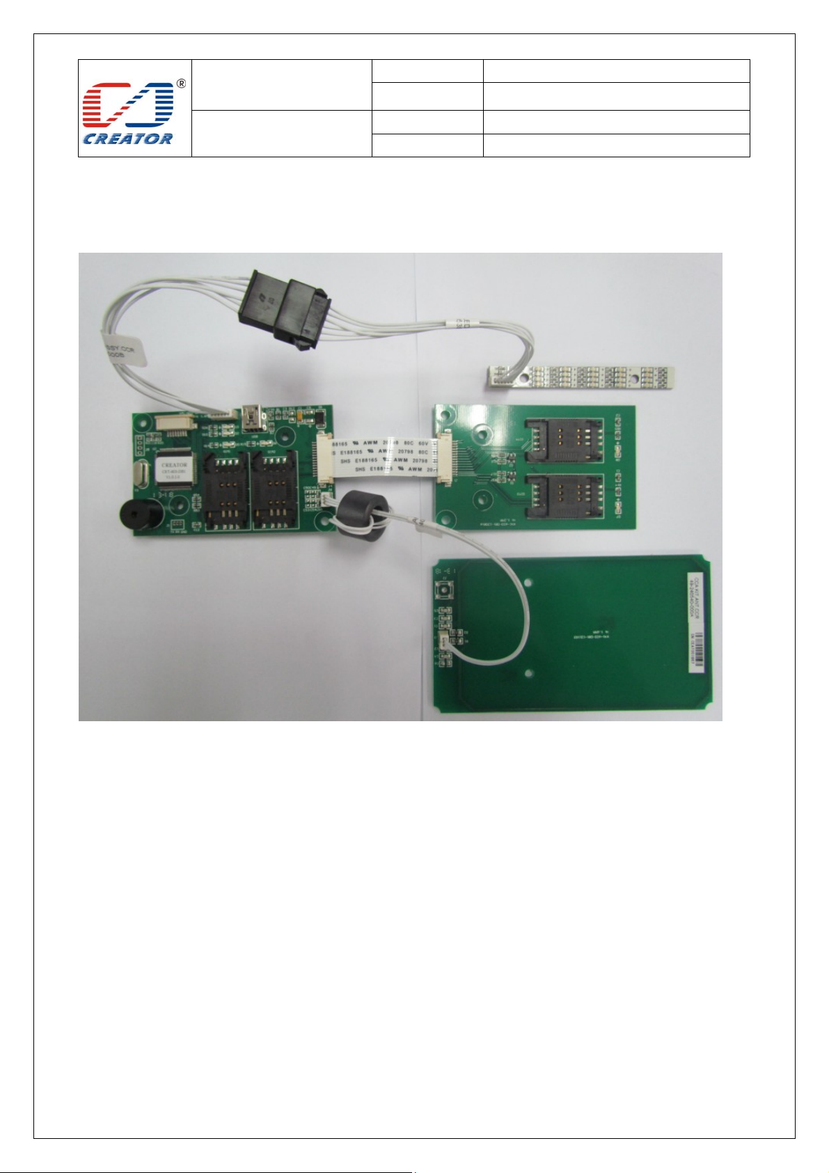
The reader has 4 main components:
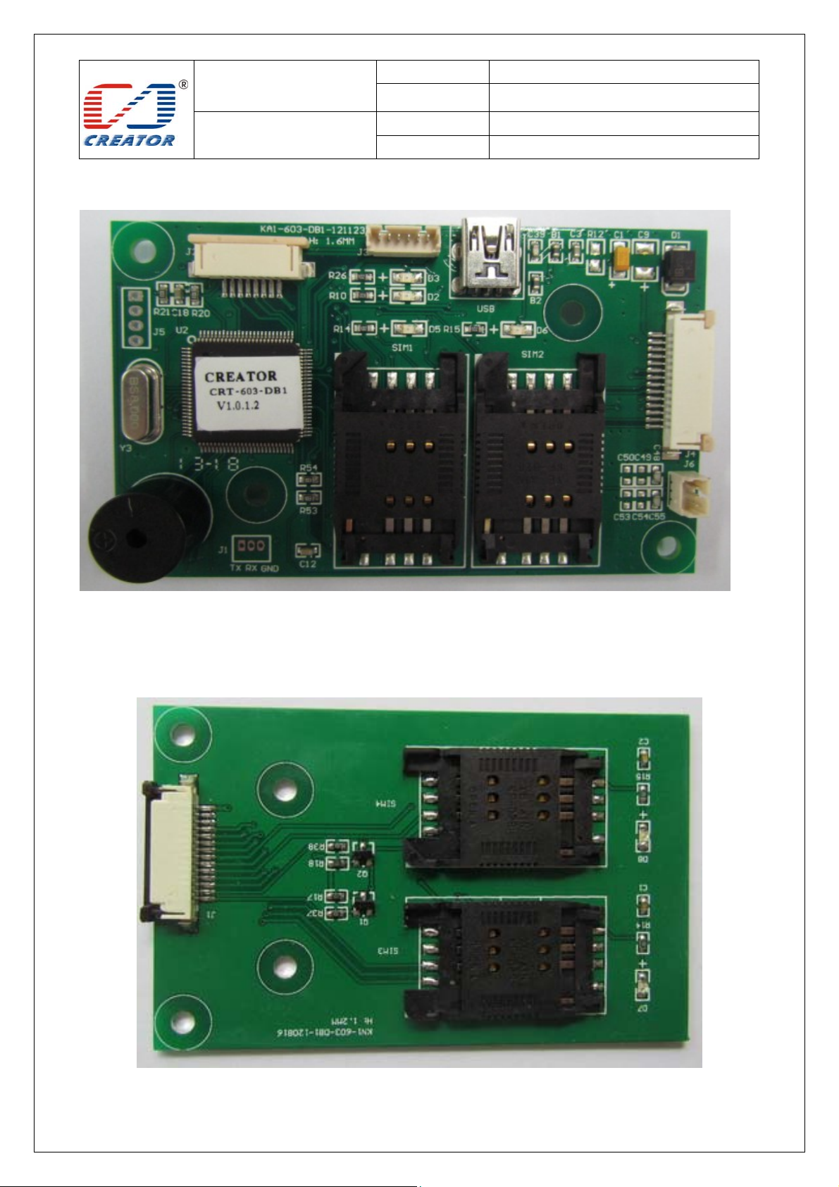
① Main board: including 2 SAM card slots and 1 USB interface, onboard power indicator, USB connection
indicator, buzzer
②SAM card board: including 2 SAM slots, the SAM card board is connected to main board with a 14 pins
FPC flat cable
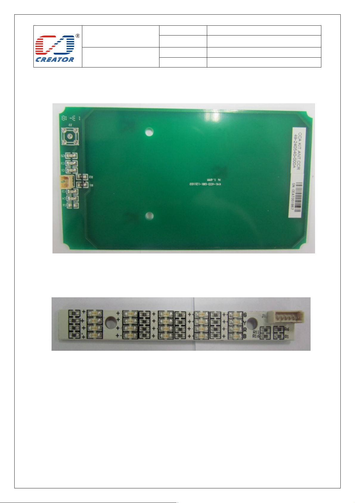
③ Antenna board: connected to main board with a 3 pins cable
④ LED board: Red, Green, Blue and Yellow LED lights, the LED board is connected to main board with a 6
pins cable
Page 9
SPECIFICATION
Model No.
Date
CRT-603-DB1
2012/11/24
Images of boards
User Manual
File Ver . 1.0
Page 9/48
Main board
SAM card board
Page 10
SPECIFICATION
Model No.
Date
CRT-603-DB1
2012/11/24
User Manual
File Ver . 1.0
Page 10/48
Antenna board
LED board
Page 11
SPECIFICATION
Model No.
Date
CRT-603-DB1
2012/11/24
User Manual
File Ver . 1.0
Page 11/48
2.2 Reader function
Note: Contactless card interface and SAM card interface are independent with each other. Reader supports
operation in parallel.
2.2.1 Contactless Card interface function
1. Read/write ISO14443-4 standard Type A&B contactless card
2. Read/write ISO14443-3 standard Mifare one S50, S70 and UL etc contactless Storage Card
3.Reader will automatically detect whether a card is present. The card will remain to be activated without
interfered by other new cards presented.
4. When more than one card access into the detection area at the same time, card collision will occur, the result
caused by card collision is as following
Card state Detection result ATR reported
One TYPE A card Detect one TYPE A card and activate the card TYPE A card ATR
More than one TYPE A card Detect more than one TYPE A card, not able
to activate any card
One TYPE B card Detect one TYPE B card and activate the card TYPE B card ATR
More than one TYPE B card Detect more than one TYPE B card,
deactivate any card
One TYPE A and one TYPE B
card
More than one TYPE A and
more than one TYPE B card
5.Contactless card reader also provides EEPROM operation, buzzer operation, LED operation, card reader restart,
get firmware version and jump to IAP mode functions. User can use these functions by extended capabilities
command and APDU commands defined by supplier.
Detect more than one card, deactivate any
card
Detect more than one card, deactivate any
card
2.2.2 SAM card reader interface function:
1.User can choose one SAM slot from the 4 SAM slots to read/write SAM card
2.’Disconnect Reader’ command’ will not power off SAM card slot.
3.SAM card reader interface provides change card slot, check SAM card board and SAM card slot status function
(by use of extended capabilities commands)
Special ATR ( indicate
card collision )
Special ATR ( indicate
card collision )
Special ATR ( indicate
card collision )
Special ATR ( indicate
card collision)
Page 12

SPECIFICATION
Model No.
Date
CRT-603-DB1
2012/11/24
User Manual
File Ver . 1.0
Page 12/48
3 Card Operation
3.1 Contact Card Environment Specifics
Note: Only use the SAM card reader
3.1.1 ATR of SAM Card
Reader report card present status will automatically to ICC Resource Manager after SAM card reset is successful.
Card ATR will be sent to application after user sends ‘Change SAM Slot’ command and ‘Connect Reader’
command.
3.1.2 APDU Command of SAM Card
Note: Please refer to COS document of the card for more detail APDU commands
Page 13

SPECIFICATION
Model No.
Date
CRT-603-DB1
2012/11/24
User Manual
File Ver . 1.0
Page 13/48
3.2 Contactless Card Environment Specifics
Note: Only use the RF card reader
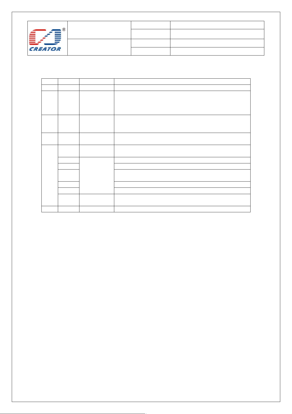
3.2.1 ATR of Contactless Card
When the reader detects a contactless smart card, reader will report card present status to ICC Resource Manager
automatically. Card ATR will be sent to application after user chooses RF reader and sends ‘Connect Reader’
command.
3.2.1.1 ATR of Contactless Smart Card
Byte Value Designation Description
0 3B Initial Header
1 8n T0 Higher nibble 8 means no TA1, TB1, TC1 only TD1 is
following.
Lower nibble n is the number of historical bytes (HistByte 0 to
HistByte n-1)
2 80 TD1 Higher nibble 8 means no TA2, TB2, TC2 only TD2 is
following.
Lower nibble 0 means T = 0
3 01 TD2 Higher nibble 0 means no TA3, TB3, TC3, TD3 following
Lower nibble 1 means T = 1
4
to
3+n
4+n XX TCK Exclusive-OR of bytes T0 to Tk
Example:
a. TYPE A card ATR :3B 8F 80 01 78 80 90 02 20 90 00 3F 38 70 04 B6 49 70 67 4F
b. TYPE B card ATR: 3B 8C 80 01 50 20 02 22 52 55 55 55 55 00 81 C1 4F
Note: When ISO14443A historical bytes T1-Tk greater than 15 bytes, the reader only reported to the last 15
historical bytes of data。
XX
XX
XX
T1
…
..
Tk
Historical bytes:
ISO14443A:
The historical bytes from ATS response. Refer to the
ISO14443-4 specification.
ISO14443B:
Byte1-4---- Application Data from ATQB
Byte5-7---- Protocol Info Byte from ATQB
Byte 8 ----Higher nibble = MBLI from ATTRIB command
Lower nibble (RFU) = 0
Page 14
SPECIFICATION
Model No.
Date
CRT-603-DB1
2012/11/24
User Manual
File Ver . 1.0
Page 14/48
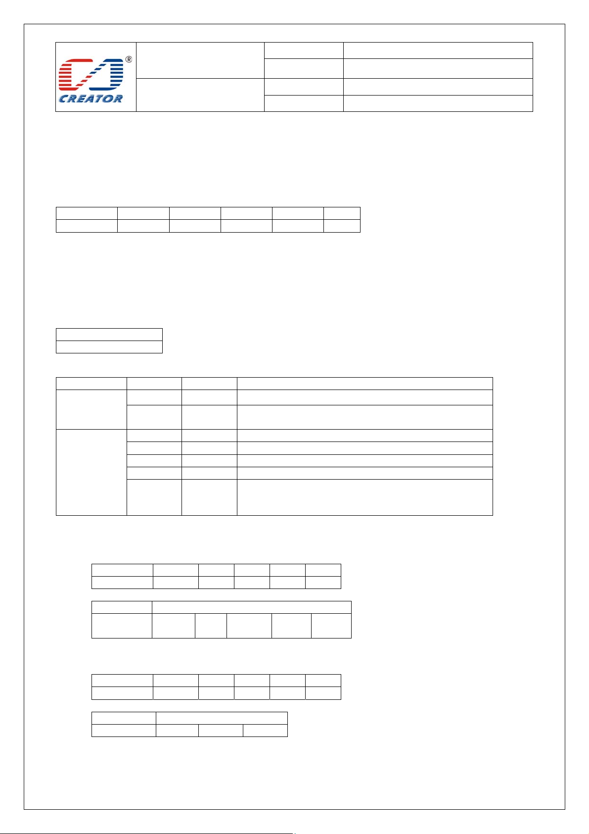
3.2.1.2 ATR of Contactless Storage Card
Byte Value Designation Description
0 3B Initial
1 8n T0 Higher nibble 8 means: no TA1, TB1, TC1 only TD1 is
following.
Lower nibble n is the number of historical bytes (HistByte 0 to
HistByte n-1)
2 80 TD1 Higher nibble 8 means: no TA2, TB2, TC2 only TD2 is
following.
Lower nibble 0 means T = 0
3 01 TD2 Higher nibble 0 means no TA3, TB3, TC3, TD3 following.
Lower nibble 1 means T = 1
4
To
3+N
4+N UU TCK Exclusive-oring of all the bytes T0 to Tk
C0 C1 is 0001 suggest the card is S50 card, 00 02 suggest S70 card,
For example:
S50 card ATR: 3B 8F 80 01 80 4F 0C A0 00 00 03 06 03 00 01 00 00 00 00 6A
S70 card ATR: 3B 8F 80 01 80 4F 0C A0 00 00 03 06 03 00 02 00 00 00 00 69
Note: The naming method for other types of cards can be found in supplementary file in PC/SC section 3.
When RF card conflicts with each other, returned ATR:
3B 8F 80 01 80 4F 0C A0 00 00 03 06 03 00 01 E0 00 00 01 8B
80 T1 Category indicator byte, 80 means A status indicator may be
present in an optional COMPACT-TLV data object
4F Tk Application identifier Presence Indicator
0C Length
RID Registered Application Provider Identifier (RID) # A0 00 00
03 06
SS Byte for standard
C0 C1 Bytes for card name
00 00
00 00
RFU RFU # 00 00 00 00
Page 15
SPECIFICATION
Model No.
Date
CRT-603-DB1
2012/11/24
User Manual
File Ver . 1.0
Page 15/48
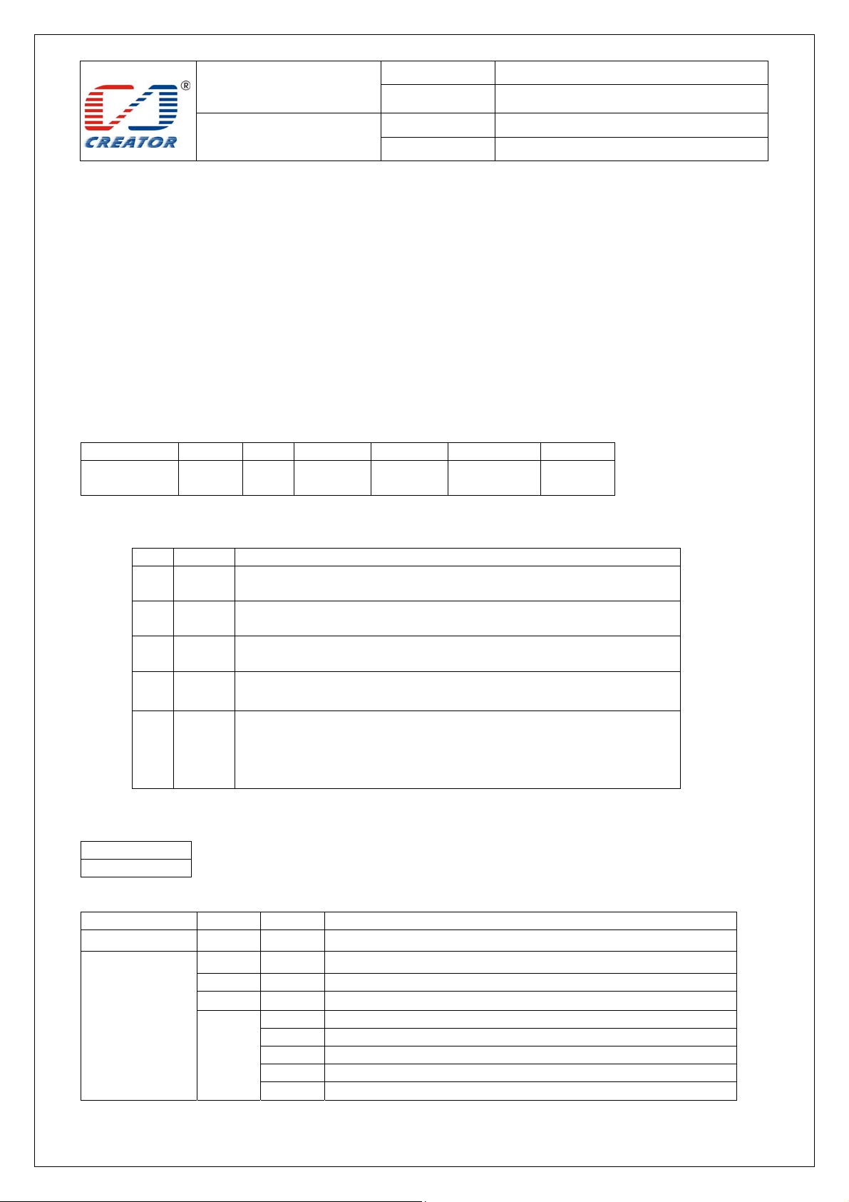
3.2.2 APDU Command of Contactless Card
3.2.2.1 Get Data Command
Get UID or ATS of the contactless card
Command format:
Command Class INS P1 P2 Le
Get Data 0xFF 0xCA XX 0x00 XX
Parameter Description:
P1 = 0 UID is returned.
P1 = 1 all historical bytes from the ATS of a ISO 14443 A card without CRC are returned.
Le = 0x00, this means: Return full length of the data (e.g. for ISO14443A single 4 bytes, double 7 bytes, triple 10
bytes, for ISO14443B 4 bytes PUPI, for 15693 8 bytes UID).
Return format:
Data Out
Data + SW1 SW2
SW1 SW2 STATUS CODE:
Success 90 00 Command execution successfully
Fail 67 00 Wrong length
Example:
A. Get UID APDU:
Command:
Command Class INS P1 P2 Le
Get Data FF CA 00 00 00
Return:
Response Data Out
Result UID
B. Get ATS APDU:
Command:
Command Class INS P1 P2 Le
Get Data FF CA 01 00 00
Return:
Response Data Out
Result ATS SW1 SW2
SW1 SW2 Meaning
62 82 End of data reached before Le bytes (Le is greater than
data length).
68 00 Class byte is not correct
6A 81 Function not supported.
6B 00 Wrong parameter P1-P2
6C XX Wrong length (wrong number Le; 'XX' encodes the exact
number) if Le is less than the available UID length)
(LSB)
…… UID
(MSB)
SW1 SW2
Page 16
SPECIFICATION
Model No.
Date
CRT-603-DB1
2012/11/24
User Manual
File Ver . 1.0
Page 16/48
3.2.2.2 Smart Card Functionality Support
Note: Please refer to COS document of the card for more detail APDU commands
3.2.2.3 Storage Card Functionality Support
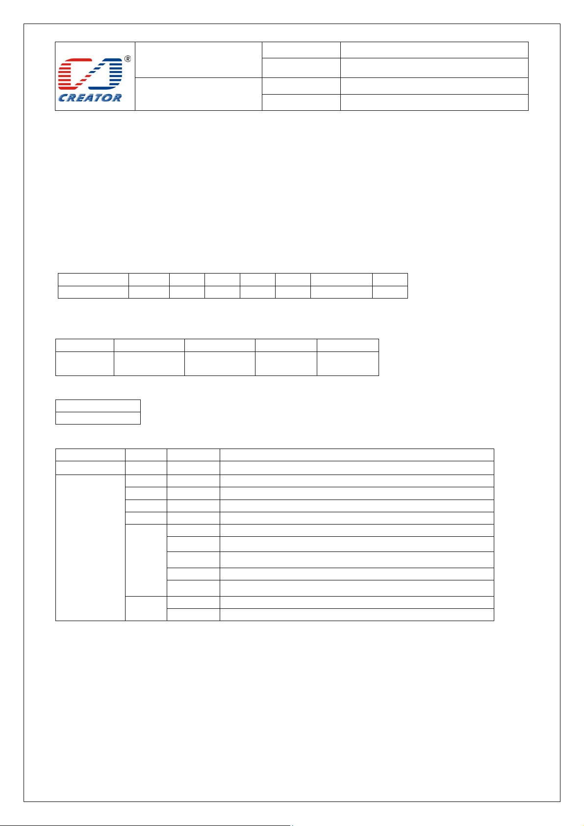
This section defines commands for Storage Cards (Exception: The Get UID and Load Key command, which
may be used for all kinds of contactless cards):
3.2.2.3.1
32 groups password can be saved into the IFD volatile memory and 1 group password can be saved into the IFD
non-volatile memory
Command format::
Command Class INS P1 P2 Lc Data In
Load Keys 0xFF 0x82 Key
Parameter Description:
Load Key (Password)
The ‘Load key’ command will just load (write) the keys(Mifare key) in the IFD designated memory.
Key
Structure
P1:
Bit
Value
7
0
6
0
5
1
4
0~3 0000 If b6 is set, it is the Reader Key number that has been used for the
Description
0: Card Key;
1 Reader Key
0: Plain Transmission,
1: Secured Transmission
0: Keys are loaded into the IFD volatile memory
1: Keys are loaded into the IFD non-volatile memory.
0:Key type is KEY_A1:Key type is KEY_B , (for non-vol atile
memory.)
encryption, else it is ignored by the IFD.
The maximum of 16-reader keys is possible. Typically an IFD uses two
reader keys only.
number
Key Length Key
P2: indicating Key number, range: 0x00~0x1F
Return format:
Data Out
SW1 SW2
SW1 SW2 STATUS CODE:
Success 90 00 Command execution successfully
Fail 63 00 Command execution failed
SW1 SW2 Meaning
67 00 Wrong length
68 00 Class byte is not correct
69 82 Card key not supported
83 Reader key not supported
85 Secured transmission not supported
88 Key type not known
89 Key length is not correct
Page 17
SPECIFICATION
Model No.
Date
CRT-603-DB1
2012/11/24
User Manual
File Ver . 1.0
Page 17/48
Example:
Load Key FFFFFFFFFFFF into RAM, APDU command:
FF 82 00 00 06 FF FF FF FF FF FF.
3.2.2.3.2
The application provides the number of the key used for the authentication. The specific key must be already
in the reader. So
Command format:
Command Class INS P1 P2 Lc Data In Le
Authenticate 0xFF 0x86 0x00 0x00 5 See table -
Parameter Description:
Data In table
Byte 1 Byte 2 Byte 3 Byte 4 Byte 5
Version
0x01
Return format:
Data Out
SW1 SW2
SW1 SW2 STATUS CODE
Success 90 00 Command execution successfully
Fail 63 00 Command execution failed
Example:
Remark:
Authenticate Key(Password)
Load Key (password) into RF reader before Authenticate sector Key of S50, S70
0x00 Block umber Key type Key Nr
SW1 SW2 Meaning
65 81 Memory failure, addressed by P1-P2 is does not exist
67 00 Wrong length
68 00 Class byte is not correct
69
6A 81 Function not supported.
Use group 0 Key under type KEY A mode to Authenticate 2th section’s Key:
F 86 00 00 05 01 00 02 60 00
1. Version: This is used in the future to differentiate different version of this command, it is 0x01
2. Block Number: The sector NO. of the specific sector that need PIN verification
3. Key type:The type of the key. for Mifare one S50/S70 ,KEY_A (0x60) or KEY_B (0x61)
4. Key Nr.: The card key number, which will be used for this authentication
82 Security status not satisfied.
83 Authentication cannot be done
84 key not useable
86 Key type not known
88 Key number not valid
82 Addressed block or byte does not exist.
Page 18
SPECIFICATION
Model No.
Date
CRT-603-DB1
2012/11/24
User Manual
File Ver . 1.0
Page 18/48
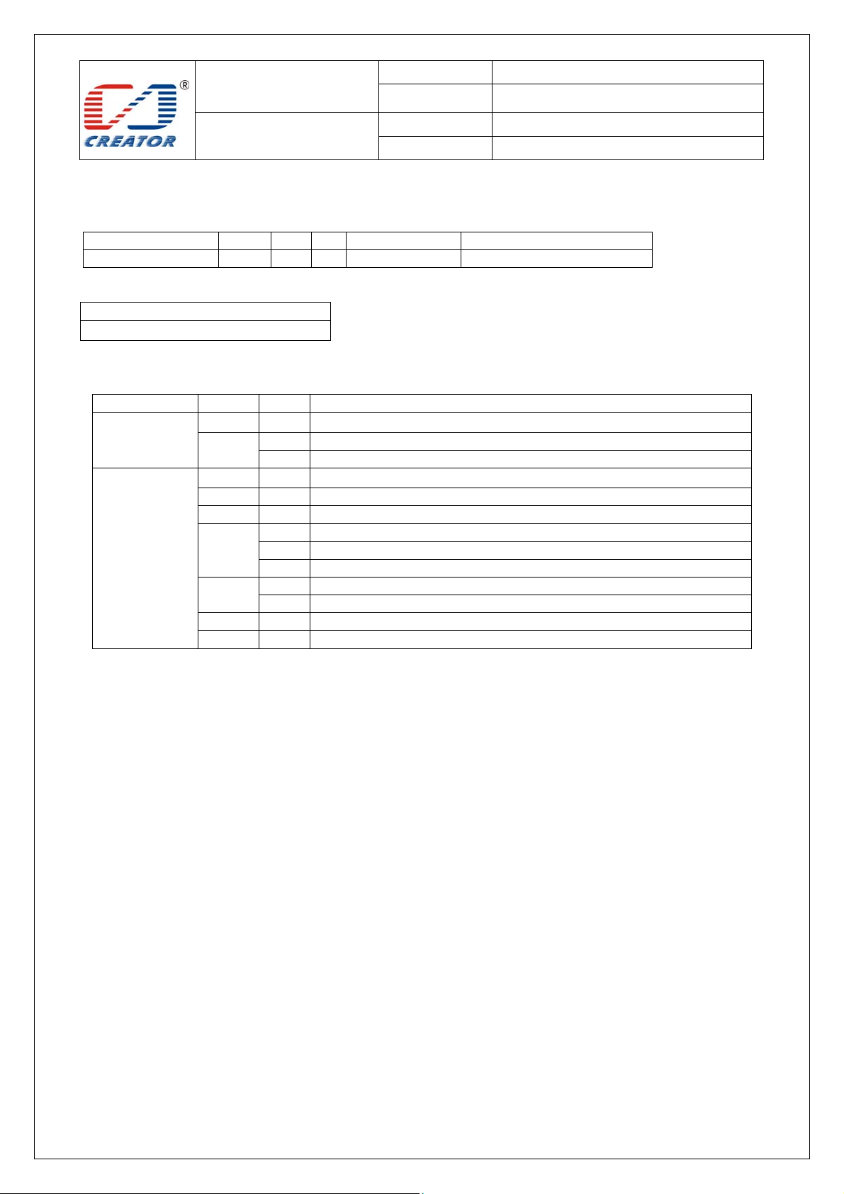
3.2.2.3.3 Read Block Data
Command format:
Command Class INS P1 P2 Le
Read Blocks data FF B0 00 Block Number Number of Bytes to Read
Return format:
Data Out
Data (0~16 byte)+ SW1 SW2
SW1 SW2 STATUS CODE:
Success 90 00 Command execution successfully
Fail 63 00 Command execution failed
Example:
Read 16 bytes data of 2
FF B0 00 02 10
Note:
Le: specify that you want to return the number of bytes. When Le=00, return of all the data.
SW1 SW2 Meaning
62 81 Part of returned data may be corrupted.
82 End of file reached before reading expected number of bytes
67 00 Wrong length
68 00 Class byte is not correct
69 81 Command incompatible.
82 Security status not satisfied.
86 Command not allowed.
6A 81 Function not supported.
82 End of data reached before Le bytes (Le is greater than data length).
6B 00 Wrong parameter P1-P2
6C XX Wrong length (wrong number Le; ‘XX’ is the exact number).
nd
sector:
Page 19
SPECIFICATION
Model No.
Date
CRT-603-DB1
2012/11/24
User Manual
File Ver . 1.0
Page 19/48
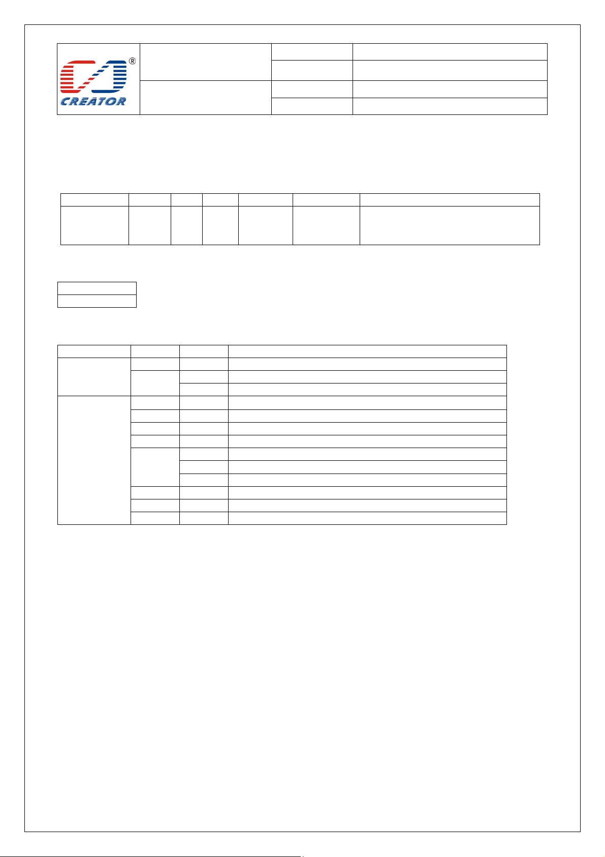
3.2.2.3.4 Update Block Command
Update Block Command APDU
Command format:
Command Class INS P1 P2 Lc Data In
Update
Blocks data
Return format:
Data Out
SW1 SW2
SW1 SW2 STATUS CODE:
Success
Fail
Example:
Write 16 byte data in 2
FF D6 00 02 10 00 01 02 03 04 05 06 07 08 09 0A 0B 0C 0D 0E 0F
Note: 4 Bytes for MIFARE Ultralight or 16 Bytes for MIFARE 1K/4K
FF D6 00 Block
Number
SW1 SW2 Meaning
90 00 Command execution successfully
62 81 Part of returned data may be corrupted.
82 End of file reached before reading expected number of bytes
63 00 Command execution failed
65 81 Memory failure (unsuccessful storing).
67 00 Wrong length
68 00 Class byte is not correct
69 81 Command incompatible.
82 Security status not satisfied.
86 Command not allowed.
6A 81 Function not supported.
6A 82 File not found / Addressed block or byte does not exist.
6B 00 Wrong parameter P1-P2
nd
sector, APDU command,
Number of
Bytes to
Update
Block Data
Page 20
SPECIFICATION
Model No.
Date
CRT-603-DB1
2012/11/24
User Manual
File Ver . 1.0
Page 20/48
4 Extended Command (Extended Capabilities)
Extended Function of card reader module is controlled by that of PC/SC protocol. Please refer to 6.1.8 for
《 Interoperability Specification for ICCs and Personal Computer Systems Part 9. IFDs with Extended
Capabilities》 and《 Specification for Integrated Circuit(s) Cards Interface Devices》 for the description of PC/SC
extended commands.
Extended commands for RF card reader are different from those for SAM card reader, please make a
difference when usage. Send unknown extended commands to card reader, it would return status code 6B
00
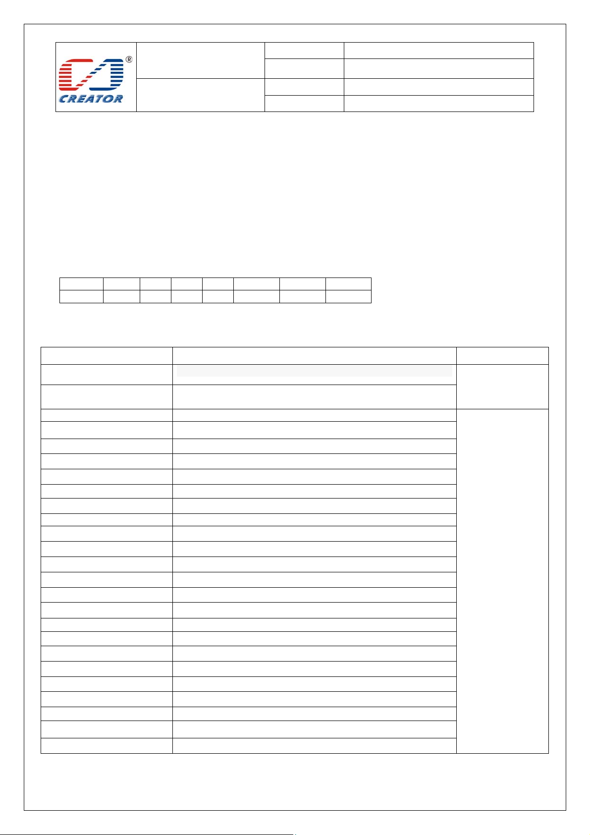
All extended commands use ‘68 92’ as Information Header, command format is as follows:
Class INS P1 P2 Le Data1 Data2 …
68 92
XX XX XX XX XX XX
4.1 Extended Command Brief Introduction
Extended command sheet
Extended Command
Choose SAM Card Slot In multiple SAM card slot, choose one SAM card to active SAM Reader
Description Use Reader Modle
Get SAM card board and
SAM slot status
Switch LED Working Mode
Inquire LED Working Mode
HOST Controls LED
Inquire LED status
Enable/Disable Buzzer Beep
Control Buzzer Beep
Write EEPROM
Read EEPROM
Write P/N
Read P/N
Write Serial Number
Read Serial Number
Write Vendor MFG Date
Read Vendor MFG Date
Write Vendor MFG P/F
Read Vendor MFG P/F
Write Diebold MFG Date
Read Diebold MFG Date
Write Diebold MFG P/F
Read Diebold MFG P/F
Get firmware version
Restart Reader
Get status of reader, if SAM card board is effective and if one
card in each SAM card slot
RF Reader
Enter IAP Mode With IAP tool to download firmware updates
Page 21
SPECIFICATION
Model No.
Date
CRT-603-DB1
2012/11/24
User Manual
File Ver . 1.0
Page 21/48
4.2 Extended Command Detail Description
4.2.1 Choose SAM Card Slot
This command is for switching SAM slot and activates any of the cards among the 4 of the SAM slots. Return
code refers to the activating results.
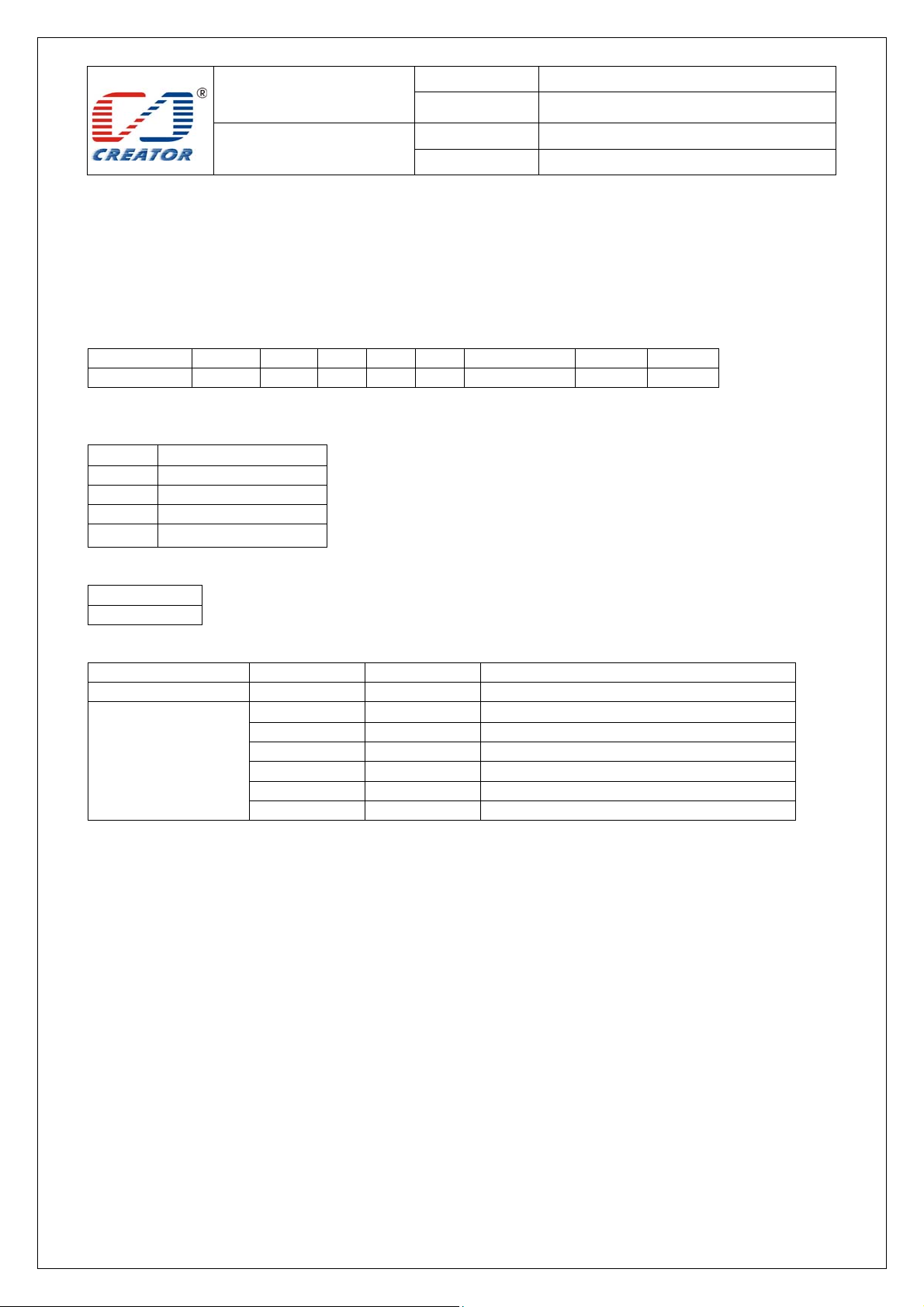
Command format:
Command Class INS P1 P2 Le Data1 Data2 Data3
Choose slot 68 92 01 00 03 Slot number 00 00
Parameter Description
Slot number:
Value Description
01 Switch to SAM1 slot
02 Switch to SAM2 slot
03 Switch to SAM3 slot
04 Switch to SAM4 slot
Return format
Data Out
SW1 SW2
SW1 SW2 STATUS CODE:
Success 90 00 Card activation successful
Fail 63 00 Card activation failed
Example:
Choose SAM Card Slot, 68 92 01 00 03 01 00 00
Note:
1. When the SAM expansion board is not connected, only two SAM card slots on the motherboard can be used.
2. Before execute switching SAM card slot, recommended inquire the SAM card board status, inquiry the card slot is in
the presence of the card
SW1 SW2 Meaning
67 00 Wrong length
68 00 Class byte is not correct
69 00 Wrong data parameter
6A 81 Function not supported
6B 00 Wrong parameter P1-P2
Page 22
SPECIFICATION
Model No.
Date
CRT-603-DB1
2012/11/24
User Manual
File Ver . 1.0
Page 22/48
4.2.2 Get SAM card board and SAM slot status
Get status of reader, if SAM card board is effective and if one card in each SAM card slot.
Command format:
Command Class INS P1 P2 Lc
Get SAM Slot Status 68 92 04 00 02
Return format:
Data Out
Data1 Data2 + SW1 SW2
Return data description:
Data1= 0 no SAM card board
Data1= 1 SAM card board is effective
Data2: SAM card slot detection result
Bit Description
7
6
5
4
3
2
1
0
SW1 SW2 STATUS CODE:
Success 90 00 Command execution successfully
Fail 63 00 Command execution failed
Example:
0:Remain
0:Remain
0:Remain
0:Remain
0:No card in SAM4 slot
1:Card in SAM4
0:No card in SAM3 slot
1:Card in SAM3
0:No card in SAM2 slot
1:Card in SAM2
0:No card in SAM1 slot
1:Card in SAM1
SW1 SW2 Meaning
67 00 Wrong length
68 00 Class byte is not correct
69 00 Wrong data param eter
6A 81 Function not supported
6B 00 Wrong parameter P1-P2
Get SAM card board and SAM slot status, 68 92 04 00 02
Page 23

SPECIFICATION
Model No.
Date
CRT-603-DB1
2012/11/24
User Manual
File Ver . 1.0
Page 23/48
4.2.3 LED Control Rules
The LED control rules are as follows:
LED indicator status (Note: Reader can only handle ISO14443 TYPE A card conflict. Detection TYPE A card is
given priority.)
1. When reader is standby: Green LED is on.
2. After Connect Reader command is sent:
A single card is activated, yellow LED is on. If buzzer has been enabled, user can start operate card after buzzer
gives a short beep.
If more than one card presented when reader is in standby status, red LED is on. If buzzer has been enabled,
buzzer will gives a long beep. Reader will return 6A 81 error code with any further command operation.
3. When operating card:
Yellow LED will be on when operating single card and its status will not changed by new cards which are
presented in the detection area
When a activation card which is being operating is removed, green LED is on. Reader returns to standby status.
When card conflict occurs, red LED is on. Red LED will be close and green LED is on when surplus cards are
removed or all cards are removed. Reader returns to standby status
4. When send Disconnect Reader command:
After deactivation card operation is completed, green LED is on. Card reader returns to standby status.
Send Disconnect Reader command, red LED will be on when more than one card collision occurs, red LED will
be off and green LED is on when surplus cards are removed or all cards are removed. Reader returns to standby
status.
When card conflict occurs,return ATR:
3B 8F 80 01 80 4F 0C A0 00 00 03 06 03 00 01 E0 00 00 01 8B
Page 24
SPECIFICATION
Model No.
Date
CRT-603-DB1
2012/11/24
User Manual
File Ver . 1.0
Page 24/48
4.2.4 Set LED Working Mode
Set LED current working mode to CCR automation mode or HOST control mode.
Command format:
Command Class INS P1 P2 Le Data1 Data2 Data3
Set Led Mode 68 92 02 00 03 mode 00 00
Parameter Description
Data = 0 CCR automation mode.
Data = 1 HOST control mode.
Return format:
Data Out
SW1 SW2
SW1 SW2 STATUS CODE:
Success 90 00 Command execution successfully
Fail 63 00 Command execution failed
Example:
Set to HOST control mode, 68 92 02 00 03 01 00 00
The corresponding command used of APDU channel transmission as follows
Command Class INS P1 P2 Le Data
Set Led Mode FF 69 44 42 8 68 92 02 00 03 mode 00 00
Parameter description, Return format, SW1 SW2 status code as above
Note:
When LED is working in CCR Controls mode control, LED control rules are in accordance with Section
4.2.3.
When LED is working in HOSt control mode, HOST controls LED on/off.
The current working mode status value is stored in non-volatile memory; it is still effective after restart
SW1 SW2 Meaning
67 00 Wrong length
68 00 Class byte is not correct
69 00 Wrong data parameter
6A 81 Function not supported
6B 00 Wrong parameter P1-P2
Page 25
SPECIFICATION
Model No.
Date
CRT-603-DB1
2012/11/24
User Manual
File Ver . 1.0
Page 25/48
4.2.5 Get LED Working Mode
Get LED of reader Current working mode
Command format:
Command Class INS P1 P2 Lc
Get Led Mode 68 92 02 01 01
Return format:
Data Out
Data SW1 SW2
Return data description:
Data = 0 CCR automation mode.
Data = 1 HOST control mode.
SW1 SW2 STATUS CODE:
Success 90 00 Command execution successfully
Fail 63 00 Command execution failed
Example:
Get LED of reader Current working mode: 68 92 02 01 01
The corresponding command used of APDU channel transmission as follows
Command Class INS P1 P2 Le Data
Get Led Mode FF 69 44 42 5 68 92 02 01 01
Parameter description, Return format, SW1 SW2 status code as above
SW1 SW2 Meaning
67 00 Wrong length
68 00 Class byte is not correct
69 00 Wrong data parameter
6A 81 Function not supported
6B 00 Wrong parameter P1-P2
Page 26
SPECIFICATION
Model No.
Date
CRT-603-DB1
2012/11/24
User Manual
File Ver . 1.0
Page 26/48
4.2.6 HOST Set LED Status
HOST controls the LED on/off/flash when LED is only working in HOST control mode.
Command format:
Command Class INS P1 P2 Le Data1 Data2 Data3
Set Led Status 68 92 02 02 03 Control Circle1 Circle2
Return format:
Data Out
SW1 SW2
Parameter Description
Control:
Bit Description
7 0:Yellow light not flash
1:Yellow light flash
6 0:Blue light not flash
1: Blue light flash
5 0:Green light not flash
1: Green light flash
4 0:Red light not flash
1: Red light flash
3 0:Yellow light off
1:Yellow light on
2 0: Blue light off
1: Blue light on
1 0: Green light off
1: Green light on
0 0: Red light off
1: Red light on
Bit 0 to Bit 7 means one byte, highest is Bit7 and lowest is Bit 0 (Hereinafter the same).
Circle1:
Bit Description
7-4 Yellow light flash cycle
3-0 Blue light flash cycle
Circle2:
Bit Description
7-4 Green light flash cycle
3-0 Read light flash cycle
Flash cycle:
value Description
0x0 Remain
0x1 0.25 Second
0x2 0.5 Second
0x3 0.75 Second
0x4 1 Second
0x5 1.25 Second
0x6 1.5 Second
Page 27
SPECIFICATION
Model No.
Date
CRT-603-DB1
2012/11/24
User Manual
File Ver . 1.0
Page 27/48
0x7 1.75 Second
0x8 2 Second
0x9 2.25 Second
0xA 2.5 Second
0xB 2.75 Second
0xC 3 Second
0xD 3.5 Second
0xE 4 Second
0xF 5 Second
SW1 SW2 STATUS CODE:
Success 90 00 Command execution successfully
Fail 63 00 Command execution failed
Example:
Red light flash with 0.25second cycle: 68 92 02 02 03 11 00 01
The corresponding command used of APDU channel transmission as follows
Command Class INS P1 P2 Le Data
Set Led Status FF 69 44 42 8 68 92 02 02 03 control circle1 circle2
Parameter description, Return format, SW1 SW2 status code as above
Note:
1. Only in Host Controls mode, when the LED Lighting state bit and the LED flash bit state bit of are
effective,flashing cycle is effective. Otherwise the blinking cycle is ignored.
2. When CCR automation mode,run this command will return status code 6300.
3. The current LED on/off/flash status value is stored in non-volatile memory, it is still effective after restart
SW1 SW2 Meaning
67 00 Wrong length
68 00 Class byte is not correct
69 00 Wrong data parameter
6A 81 Function not supported
6B 00 Wrong parameter P1-P2
Page 28
SPECIFICATION
Model No.
Date
CRT-603-DB1
2012/11/24
User Manual
File Ver . 1.0
Page 28/48
4.2.7 Get LED status
Inquire the status of each of the LED
Command format:
Command Class INS P1 P2 Lc
Get Led status 68 92 02 03 03
Return format:
Data Out
control circle1 circle2 + SW1 SW2
Return data description
Control, circle1, circle2, please refer to section 2.2.6
SW1 SW2 STATUS CODE:
Success 90 00 Command execution successfully
Fail 63 00 Command execution failed
Example:
Get LED status: 68 92 02 03 03
The corresponding command used of APDU channel transmission as follows
Command Class INS P1 P2 Le Data
Get Led FF 69 44 42 5 68 92 02 03 03
Parameter description, Return format, SW1 SW2 status code as above
SW1 SW2 Meaning
67 00 Wrong length
68 00 Class byte is not correct
69 00 Wrong data parameter
6A 81 Function not supported
6B 00 Wrong parameter P1-P2
Page 29
SPECIFICATION
Model No.
Date
CRT-603-DB1
2012/11/24
User Manual
File Ver . 1.0
Page 29/48
4.2.8 Enable/Disable Buzzer Beep
Enable/disable buzzer beep, and then settings are stored into non-volatile memory
Command format:
Command Class INS P1 P2 Le Data1 Data2 Data3
Beep Enable/Disable 68 92 03 00 03 mode 00 00
Return format:
Data Out
SW1 SW2
Parameter Description
Mode = 0 means disable buzzer, and buzzer will not beep when card is activated with connecting reader after
disable buzzer.
Mode = 1 means enable buzzer, and buzzer will beep automatically when card is activated with connecting reader
after enable buzzer.
Buzzer beeps shortly for single card activation, and longer for multi cards collision.
SW1 SW2 STATUS CODE:
Success 90 00 Command execution successfully
Fail 63 00 Command execution failed
Example:
Enable buzzer, 68 92 03 00 03 01 00 00
The corresponding command used of APDU channel transmission as follows
Command Class INS P1 P2 Le Data
Beep Enable/Disable FF 69 44 42 8 68 92 03 00 03 mode 00 00
Parameter description, Return format,SW1 SW2 status code as above
SW1 SW2 Meaning
67 00 Wrong length
68 00 Class byte is not correct
69 00 Wrong data parameter
6A 81 Function not supported
6B 00 Wrong parameter P1-P2
Page 30
SPECIFICATION
Model No.
Date
CRT-603-DB1
2012/11/24
User Manual
File Ver . 1.0
Page 30/48
4.2.9 Control Buzzer Beep
Dynamic control buzzer beeps.
Command format:
Command Class INS P1 P2 Le Data1 Data2 Data3
Beep Control 68 92 03 01 03 Beep time 00 00
Parameter Description
Beep Time: one unit is 100ms,
Return format:
Data Out
SW1 SW2
SW1 SW2 STATUS CODE:
Success 90 00 Command execution successfully
Fail 63 00 Command execution failed
Example:
Buzzer beeps for a second, 68 92 03 01 03 0A 00 00
The corresponding command used of APDU channel transmission as follows
Command Class INS P1 P2 Le Data
Beep Control FF 69 44 42 8 68 92 03 01 03 Beep time 00 00
Parameter description, Return format, SW1 SW2 status code as above
Note:
The command can be repeated Sending in beeping process, the the last command is as a beep time .In addition,
time = 0 to stop the buzzer beep.
SW1 SW2 Meaning
67 00 Wrong length
68 00 Class byte is not correct
69 00 Wrong data parameter
6A 81 Function not supported
6B 00 Wrong parameter P1-P2
Page 31

SPECIFICATION
Model No.
Date
CRT-603-DB1
2012/11/24
User Manual
File Ver . 1.0
Page 31/48
4.2.10 Pre-set data layout of card reader EEPROM
Note: EEPROM data is as following:
100 bytes buffer
P/N
(12 bytes)
EEPROM provides 100 bytes space, address 0~99.
P/N 0~11 address is for PN data
Serial Number 12~23 address is for Serial Number
Vendor MFG Date 24~31 address is for Vendor MFG Date
Vendor MFG P/F 32~35 address is for Vendor MFG P/F
Diebold MFG Date 36~43 address is for Diebold MFG Date
Diebold MFG P/F 44~47 address is for Diebold MFG P/F
48~99 address can be defined by user
Serial Number
(12 bytes)
Vendor MFG Date
(8 bytes)
Vendor MFG P/F
(1~4 bytes)
Diebold MFG Date
(8 bytes )
Diebold MFG P/F
(1~4 bytes)
free space
(52 bytes)
Page 32
SPECIFICATION
Model No.
Date
CRT-603-DB1
2012/11/24
User Manual
File Ver . 1.0
Page 32/48
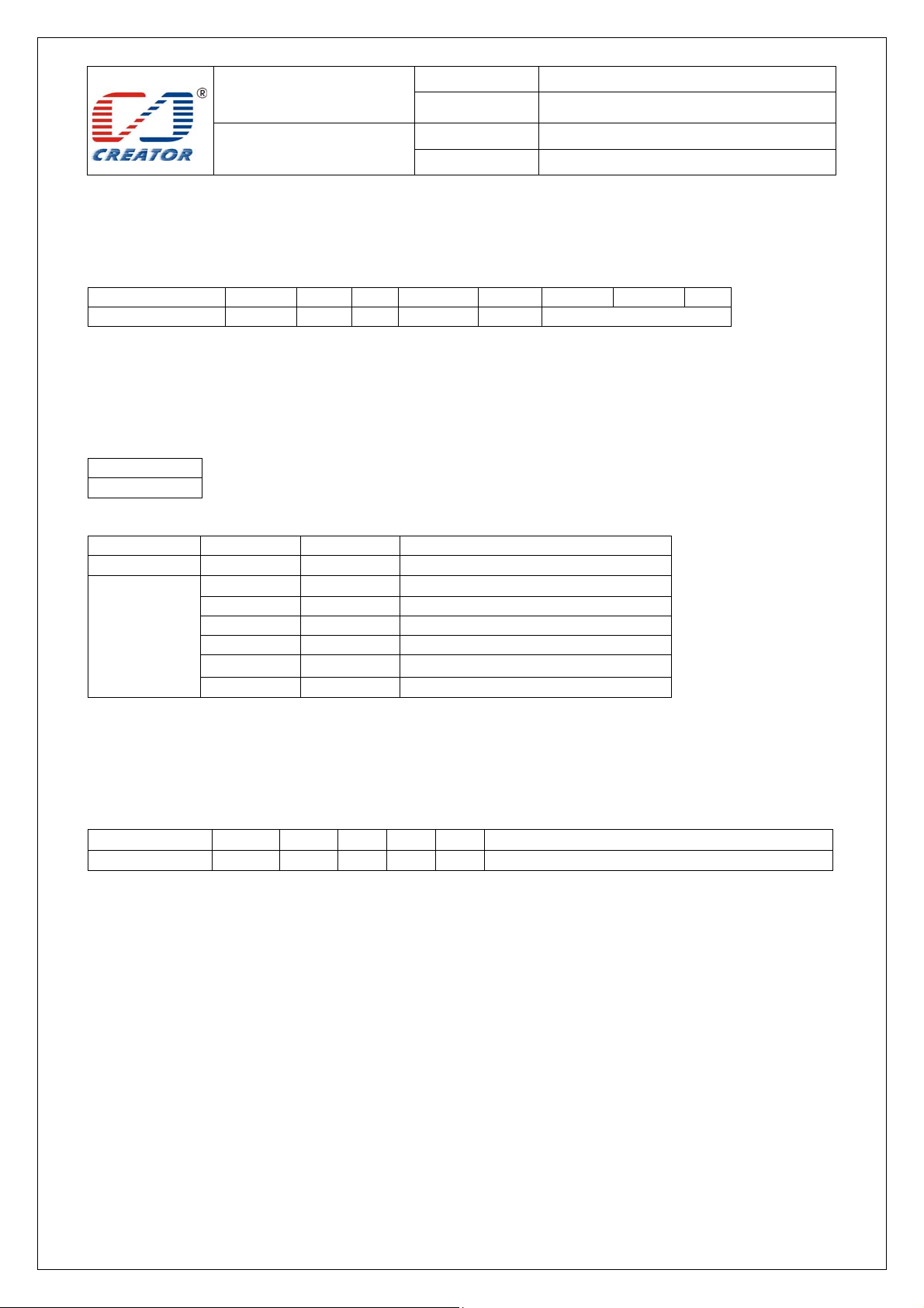
4.2.11 Write EEPROM
Write data to EEPROM
Command format:
Command Class INS P1 P2 Le Data1 Data2 …
Write EEPROM 68 92 E0 Address Length Data(1~100 bytes)
Parameter Description
Address: start address, range: 0-99
Length: length of data, range: 1-100
Data: The data to be written.
Return format:
Data Out
SW1 SW2
SW1 SW2 STATUS CODE:
Success 90 00 Command execution successfully
Fail 63 00 Command execution failed
Example:
The start address is 50, write 10 bytes of data into EEPROM, 68 92 E0 32 0A 01 02 03 04 05 06 07 08 09 0A
The corresponding command used of APDU channel transmission as follows
Command Class INS P1 P2 Le Data
Write EEPROM FF 69 44 42
Parameter description, Return format, SW1 SW2 status code as above
XX: length of Data
Note:
Users can use 100 bytes of EEPROM space, does not exceed the capacity, users can write data of any address and
any length in this space
SW1 SW2 Meaning
67 00 Wrong length
68 00 Class byte is not correct
69 00 Wrong data parameter
6A 81 Function not supported
6B 00 Wrong parameter P1-P2
XX
68 92 E0 address length Data
Page 33
SPECIFICATION
Model No.
Date
CRT-603-DB1
2012/11/24
User Manual
File Ver . 1.0
Page 33/48
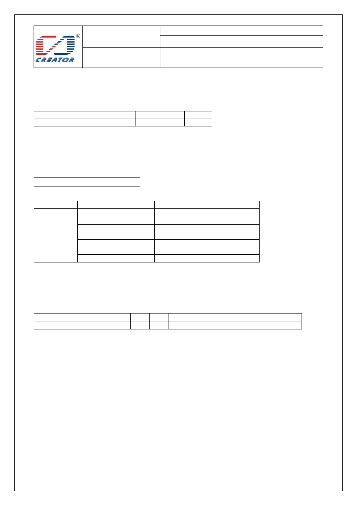
4.2.12 Read EEPROM
Read data from EEPROM
Command format:
Command Class INS P1 P2 Lc
Read EEPROM 68 92 E1 Address Length
Parameter Description:
Address: Start address 0-99
Length: length of data (1-100)
Return format:
Data Out
Data(1~100 byte)+ SW1 SW2
SW1 SW2 STATUS CODE:
Success 90 00 Command execution successfully
Fail 63 00 Command execution failed
Example:
The start address is 50, read 10 bytes of data from EEPROM, 68 92 E1 32 0A
The corresponding command used of APDU channel transmission as follows
Command Class INS P1 P2 Le Data
Read EEPROM FF 69 44 42 5 68 92 E1 address length
Parameter description, Return format, SW1 SW2 status code as above
Note:
Users can use 100 bytes of EEPROM space, does not exceed the capacity, users can read data of any address and
any length in this space
SW1 SW2 Meaning
67 00 Wrong length
68 00 Class byte is not correct
69 00 Wrong data parameter
6A 81 Function not supported
6B 00 Wrong parameter P1-P2
Page 34
SPECIFICATION
Model No.
Date
CRT-603-DB1
2012/11/24
User Manual
File Ver . 1.0
Page 34/48
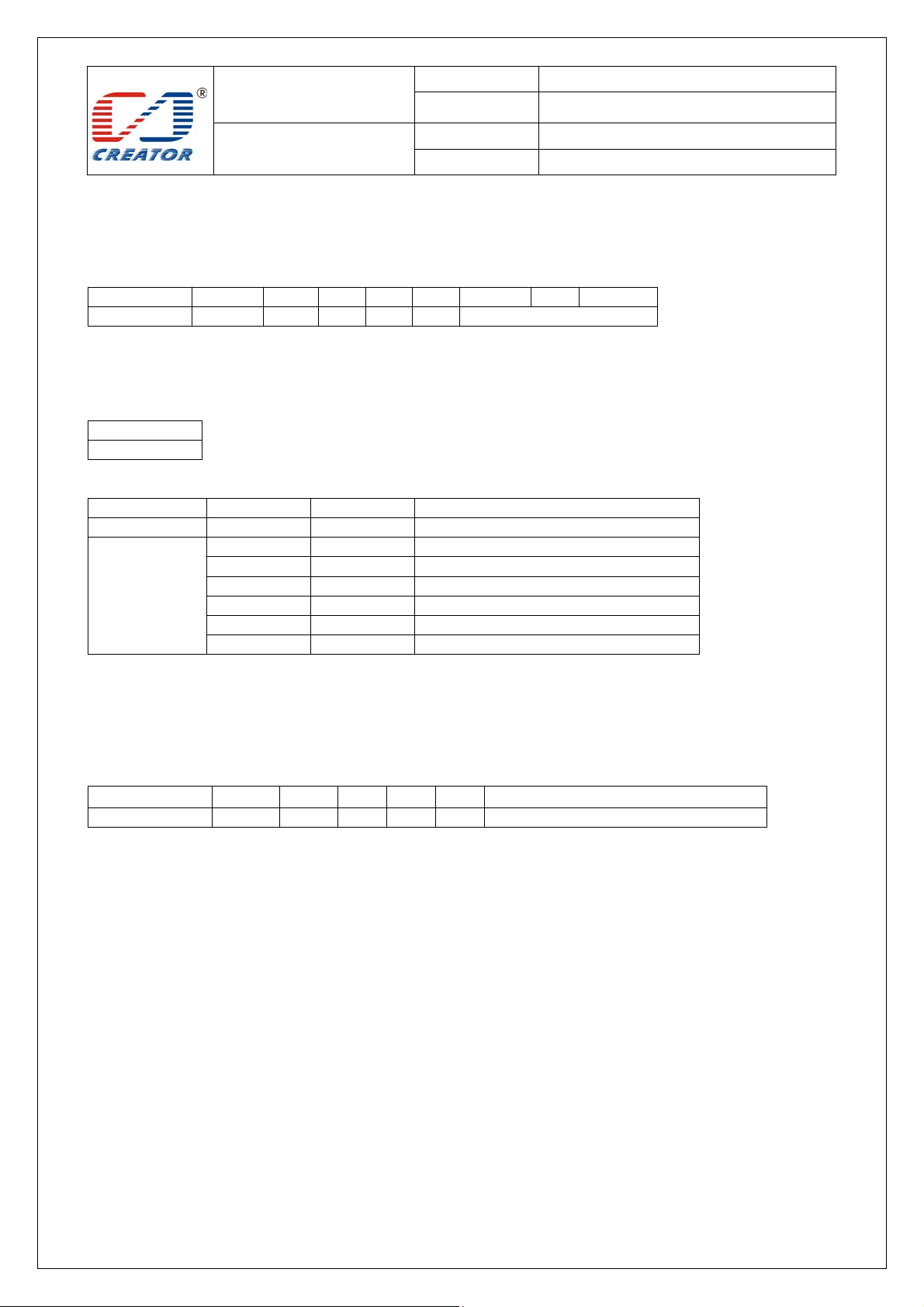
4.2.13 Write P/N
Write data of P/N to EEPROM.
Command format:
Command Class INS P1 P2 Le Data1 … Data12
Write P/N 68 92 E2 00 0C Data(12 bytes)
Parameter Description
Data: the data of P/N
Return format:
Data Out
SW1 SW2
SW1 SW2 STATUS CODE:
Success 90 00 Command execution successfully
Fail 63 00 Command execution failed
Example:
Write P/N: 68 92 E2 00 0C 61 61 62 62 63 63 64 64 65 6 5 66 66
The corresponding command used of APDU channel transmission as follows
Command Class INS P1 P2 Le Data
Write P/N FF 69 44 42 11 68 92 E2 00 0C Data
Parameter description, Return format, SW1 SW2 status code as above
SW1 SW2 Meaning
67 00 Wrong length
68 00 Class byte is not correct
69 00 Wrong data parameter
6A 81 Function not supported
6B 00 Wrong parameter P1-P2
Page 35
SPECIFICATION
Model No.
Date
CRT-603-DB1
2012/11/24
User Manual
File Ver . 1.0
Page 35/48
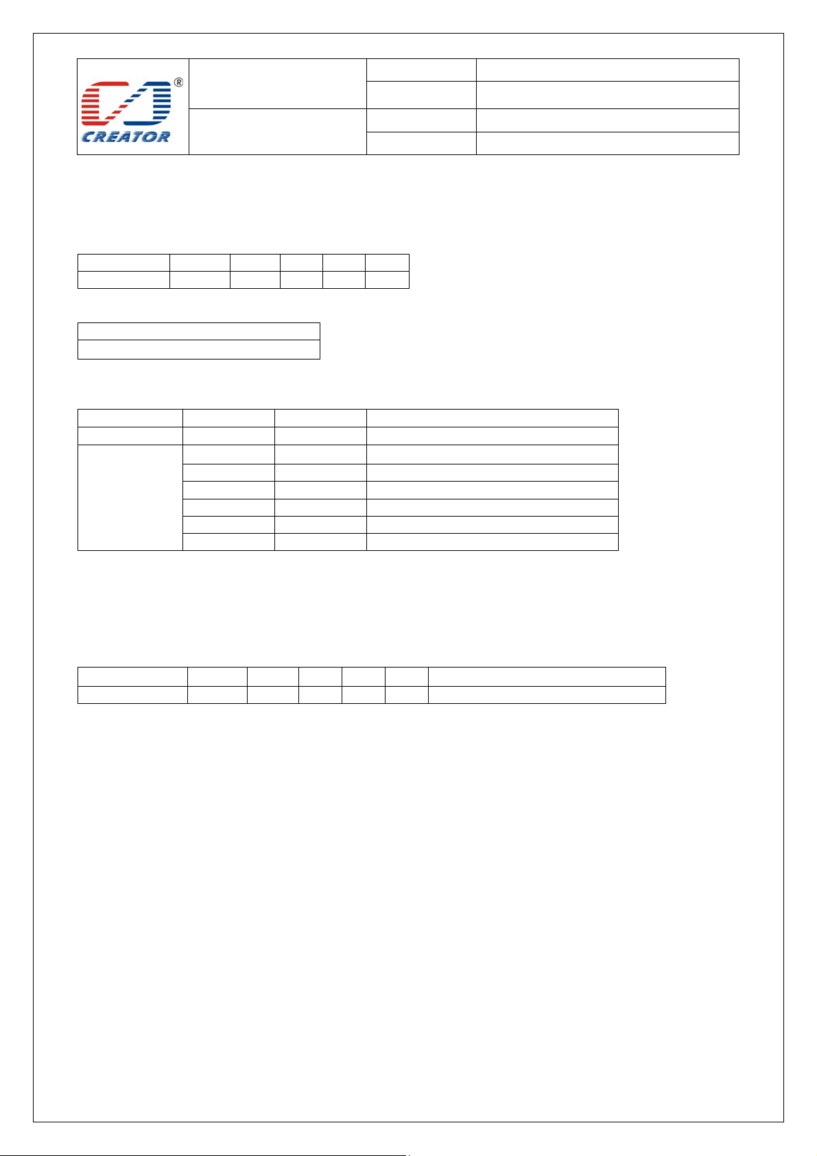
4.2.14 Read P/N
Read data of P/N from EEPROM.
Command format:
Command Class INS P1 P2 Lc
Read P/N 68 92 E2 01 0C
Return format:
Data Out
Data12 bytes)+ SW1 SW2
Data: the data of P/N
SW1 SW2 STATUS CODE:
Success
Fail
Example:
Read P/N, 68 92 E2 01 0C
The corresponding command used of APDU channel transmission as follows
Command Class INS P1 P2 Le Data
Read P/N FF 69 44 42 5 68 92 E2 01 0C
Parameter description, Return format, SW1 SW2 status code as above
SW1 SW2 Meaning
90 00 Command execution successfully
63 00 Command execution failed
67 00 Wrong length
68 00 Class byte is not correct
69 00 Wrong data parameter
6A 81 Function not supported
6B 00 Wrong parameter P1-P2
Page 36
SPECIFICATION
Model No.
Date
CRT-603-DB1
2012/11/24
User Manual
File Ver . 1.0
Page 36/48
4.2.15 Write Serial Number
Write data of Serial Number to EEPROM
Command format:
Command Class INS P1 P2 Le Data1 … Data12
Write Serial Number 68 92 E2 02 0C Data(12 bytes)
Parameter Description:
Data:data of Serial Number
Return format:
Data Out
SW1 SW2
SW1 SW2 STATUS CODE:
Success
Fail
Example:
Write data of Serial Number: 68 92 E2 02 0C 30 31 32 33 34 35 36 37 38 39 39 39
The corresponding command used of APDU channel transmission as follows
Command Class INS P1 P2 Le Data
Write Serial Number FF 69 44 42 11 68 92 E2 02 0C Data
Parameter description, Return format, SW1 SW2 status code as above
SW1 SW2 Meaning
90 00 Command execution successfully
63 00 Command execution failed
67 00 Wrong length
68 00 Class byte is not correct
69 00 Wrong data parameter
6A 81 Function not supported
6B 00 Wrong parameter P1-P2
Page 37
SPECIFICATION
Model No.
Date
CRT-603-DB1
2012/11/24
User Manual
File Ver . 1.0
Page 37/48
4.2.16 Read Serial Number
Read data of Serial Number from EEPROM
Command format:
Command Class INS P1 P2 Lc
Read Serial Number 68 92 E2 03 0C
Return format:
Data Out
Data(12 bytes)+ SW1 SW2
Data: data of Serial Number
SW1 SW2 STATUS CODE:
Success
Fail
Example:
Read data of Serial Number: 68 92 E2 03 0C
The corresponding command used of APDU channel transmission as follows
Command Class INS P1 P2 Le Data
Read Serial Number FF 69 44 42 5 68 92 E2 03 0C
Parameter description, Return format, SW1 SW2 status code as above
SW1 SW2 Meaning
90 00 Command execution successfully
63 00 Command execution failed
67 00 Wrong length
68 00 Class byte is not correct
69 00 Wrong data parameter
6A 81 Function not supported
6B 00 Wrong parameter P1-P2
Page 38
SPECIFICATION
Model No.
Date
CRT-603-DB1
2012/11/24
User Manual
File Ver . 1.0
Page 38/48
4.2.17 Write Vendor MFG Date
Write data of Vendor MFG Date to EEPROM
Command format:
Command Class INS P1 P2 Le Data1 … Data8
Write Vendor MFG Date 68 92 E2 04 08 Data(8 bytes)
Parameter Description:
Data:data of Vendor MFG Date
Return format:
Data Out
SW1 SW2
SW1 SW2 STATUS CODE:
Success
Fail
Example:
Write data of Vendor MFG Date, 68 92 E2 04 08 31 32 33 34 35 36 37 38
The corresponding command used of APDU channel transmission as follows
Command Class INS P1 P2 Le Data
Write Vendor MFG Date FF 69 44 42 D 68 92 E2 04 08 Data
Parameter description, Return format, SW1 SW2 status code as above
SW1 SW2 Meaning
90 00 Command execution successfully
63 00 Command execution failed
67 00 Wrong length
68 00 Class byte is not correct
69 00 Wrong data parameter
6A 81 Function not supported
6B 00 Wrong parameter P1-P2
Page 39
SPECIFICATION
Model No.
Date
CRT-603-DB1
2012/11/24
User Manual
File Ver . 1.0
Page 39/48
4.2.18 Read Vend or MFG Date
Read data of Vendor MFG Date from EEPROM
Command format:
Command Class INS P1 P2 Lc
Read Vendor MFG Date 68 92 E2 05 08
Return format:
Data Out
Data (8 bytes)+ SW1 SW2
Data: data of Vendor MFG Date
SW1 SW2 STATUS CODE:
Success
Fail
Example:
Read data of Vendor MFG Date, 68 92 E2 05 08
The corresponding command used of APDU channel transmission as follows
Command Class INS P1 P2 Le Data
Read Vendor MFG Date FF 69 44 42 5 68 92 E2 05 08
Parameter description, Return format, SW1 SW2 status code as above
SW1 SW2 Meaning
90 00 Command execution successfully
63 00 Command execution failed
67 00 Wrong length
68 00 Class byte is not correct
69 00 Wrong data parameter
6A 81 Function not supported
6B 00 Wrong parameter P1-P2
Page 40
SPECIFICATION
Model No.
Date
CRT-603-DB1
2012/11/24
User Manual
File Ver . 1.0
Page 40/48
4.2.19 Write Vendor MFG P/F
Write data of Vendor MFG P/F to EEPROM
Command format:
Command Class INS P1 P2 Le Data1 …
Write Vendor MFG P/F 68 92 E2 06 length Data(1~4 bytes)
Parameter Description:
Length: length of Vendor MFG P/F, Range:1~4
Data:data of Vendor MFG P/F
Return format:
Data Out
SW1 SW2
SW1 SW2 STATUS CODE:
Success 90 00 Command execution successfully
Fail 63 00 Command execution failed
Example:
Write data of Vendor MFG P/F, 68 92 E2 06 04 31 32 33 34
The corresponding command used of APDU channel transmission as follows
Command Class INS P1 P2 Le Data
Write Vendor MFG P/F FF 69 44 42
Parameter description, Return format, SW1 SW2 status code as above
XX: means length of Data
Note:
The old data of Vendor MFG P/F will be erased when writing new data
SW1 SW2 Meaning
67 00 Wrong length
68 00 Class byte is not correct
69 00 Wrong data parameter
6A 81 Function not supported
6B 00 Wrong parameter P1-P2
XX
68 92 E2 06 length Data
Page 41
SPECIFICATION
Model No.
Date
CRT-603-DB1
2012/11/24
User Manual
File Ver . 1.0
Page 41/48
4.2.20 Read Vend or MFG P/F
Read data of Vendor MFG P/F from EEPROM.
Command format:
Command
Read Vendor MFG P/F 68 92 E2 07 length
Parameter Description:
Length: length of Vendor MFG P/F, Range:1~4
Return format:
Data Out
Data (1-4byte)+ SW1 SW2
Data: data of Vendor MFG P/F
SW1 SW2 STATUS CODE:
Success 90 00 Command execution successfully
Fail 63 00 Command execution failed
Example:
Read data of Vendor MFG P/F, 68 92 E2 07 04
The corresponding command used of APDU channel transmission as follows
Command Class INS P1 P2 Le Data
Read Vendor MFG P/F FF 69 44 42 5 68 92 E2 07 XX
Parameter description, Return format, SW1 SW2 status code as above
SW1 SW2 Meaning
67 00 Wrong length
68 00 Class byte is not correct
69 00 Wrong data parameter
6A 81 Function not supported
6B 00 Wrong parameter P1-P2
Class INS P1 P2 Lc
Page 42
SPECIFICATION
Model No.
Date
CRT-603-DB1
2012/11/24
User Manual
File Ver . 1.0
Page 42/48
4.2.21 Write Diebold MFG Date
Write data of Diebold MFG Date to EEPROM
Command format:
Command Class INS P1 P2 Le Data1 … Data8
Write Diebold MFG Date 68 92 E2 08 08 Data(8 bytes)
Parameter Description:
Data:data of Diebold MFG Date
Return format:
Data Out
SW1 SW2
SW1 SW2 STATUS CODE:
Success
Fail
Example:
Wrte data Diebold MFG Date, 68 92 E2 08 08 31 32 33 34 35 36 37 38
The corresponding command used of APDU channel transmission as follows
Command Class INS P1 P2 Le Data
Write Diebold MFG Date FF 69 44 42 D 68 92 E2 08 08 Data
Parameter description, Return format, SW1 SW2 status code as above
SW1 SW2 Meaning
90 00 Command execution successfully
63 00 Command execution failed
67 00 Wrong length
68 00 Class byte is not correct
69 00 Wrong data parameter
6A 81 Function not supported
6B 00 Wrong parameter P1-P2
Page 43
SPECIFICATION
Model No.
Date
CRT-603-DB1
2012/11/24
User Manual
File Ver . 1.0
Page 43/48
4.2.22 Read Diebold MFG Date
Read data of Diebold MFG Date from EEPROM.
Command format:
Command Class INS P1 P2 Lc
Read Diebold MFG Date 68 92 E2 09 08
Return format:
Data Out
Data(8 bytes)+ SW1 SW2
Data: data of Diebold MFG Date
SW1 SW2 STATUS CODE:
Success
Fail
Example:
Read data of Diebold MFG Date, 68 92 E2 09 08
The corresponding command used of APDU channel transmission as follows
Command Class INS P1 P2 Le Data
Read Diebold MFG Date FF 69 44 42 5 68 92 E2 09 08
Parameter description, Return format, SW1 SW2 status code as above
SW1 SW2 Meaning
90 00 Command execution successfully
63 00 Command execution failed
67 00 Wrong length
68 00 Class byte is not correct
69 00 Wrong data parameter
6A 81 Function not supported
6B 00 Wrong parameter P1-P2
Page 44
SPECIFICATION
Model No.
Date
CRT-603-DB1
2012/11/24
User Manual
File Ver . 1.0
Page 44/48
4.2.23 Write Diebold MFG P/F
Write data of Diebold MFG P/F to EEPROM
Command format:
Command Class INS P1 P2 Le Data1 …
Write Diebold MFG P/F 68 92 E2 0A length Data(1~4 bytes)
Parameter Description:
Length: length of Diebold MFG P/F, Range:1~4
Data:data of Diebold MFG P/F
Return format:
Data Out
SW1 SW2
SW1 SW2 STATUS CODE:
Success 90 00 Command execution successfully
Fail 63 00 Command execution failed
Note:
The old data of Diebold MFG P/F will be Erased when writing new data
Example:
Write data of Diebold MFG P/F, 68 92 E2 0A 04 31 32 33 34
The corresponding command used of APDU channel transmission as follows
Command Class INS P1 P2 Le Data
Write Diebold MFG P/F FF 69 44 42
Parameter description, Return format, SW1 SW2 status code as above
XX: length of Data.
SW1 SW2 Meaning
67 00 Wrong length
68 00 Class byte is not correct
69 00 Wrong data parameter
6A 81 Function not supported
6B 00 Wrong parameter P1-P2
XX
68 92 E2 0A length Data
Page 45
SPECIFICATION
Model No.
Date
CRT-603-DB1
2012/11/24
User Manual
File Ver . 1.0
Page 45/48
4.2.24 Read Diebold MFG P/F
Read data of Diebold MFG P/F from EEPROM.
Command format:
Command
Read Diebold MFG P/F 68 92 E2 0B Length
Parameter Description:
Length: length of data, range: 1~4.
Return format:
Data Out
Data (1-4byte)+ SW1 SW2
Data: data of Diebold MFG P/F
SW1 SW2 STATUS CODE:
Success 90 00 Command execution successfully
Fail 63 00 Command execution failed
Example:
Read data of Diebold MFG P/F, 68 92 E2 0B 04
The corresponding command used of APDU channel transmission as follows
Command Class INS P1 P2 Le Data
Read Diebold MFG P/F FF 69 44 42 5 68 92 E2 0B Length
Parameter description, Return format, SW1 SW2 status code as above
SW1 SW2 Meaning
67 00 Wrong length
68 00 Class byte is not correct
69 00 Wrong data parameter
6A 81 Function not supported
6B 00 Wrong parameter P1-P2
Class INS P1 P2 Lc
Page 46
SPECIFICATION
Model No.
Date
CRT-603-DB1
2012/11/24
User Manual
File Ver . 1.0
Page 46/48
4.2.25 Get Fir mware Version
Get firmware version number of Reader
Command format:
Command Class INS P1 P2 Lc
Get Firmware Version 68 92 00 05 00
Return format:
Data Out
Data1 Data2 … + SW1 SW2
Bellow shows example of firmware version number:
V1.0.0.1
SW1 SW2 STATUS CODE:
Success 90 00 Command execution successfully
Fail 63 00 Command execution failed
Example:
Get firmware version of Reader, 68 92 00 05 00
The corresponding command used of APDU channel transmission as follows
Command Class INS P1 P2 Le Data
Get Firmware Version FF 69 44 42 5 68 92 00 05 00
Parameter description, Return format, SW1 SW2 status code as above
SW1 SW2 Meaning
67 00 Wrong length
68 00 Class byte is not correct
69 00 Wrong data parameter
6A 81 Function not supported
6B 00 Wrong parameter P1-P2
Page 47
SPECIFICATION
Model No.
Date
CRT-603-DB1
2012/11/24
User Manual
File Ver . 1.0
Page 47/48
4.2.26 Restart Reader
Restart Read, Reader firmware to re-power。
Command format:
Command Class INS P1 P2 Le Data1 Data2 Data3
Restart Reader 68 92 80 FF 03 4B 30 00
Return format
Data Out
SW1 SW2
SW1 SW2 STATUS CODE:
Success
Fail
Example:
Restart Reader, 68 92 80 FF 03 4B 30 00
The corresponding command used of APDU channel transmission as follows
Command Class INS P1 P2 Le Data
Restart Reader FF 69 44 42 8 68 92 80 FF 03 4B 30 00
Parameter description, Return format, SW1 SW2 status code as above
Note:
SW1 SW2 Meaning
90 00 Command execution successfully
63 00 Command execution failed
67 00 Wrong length
68 00 Class byte is not correct
69 00 Wrong data parameter
6A 81 Function not supported
6B 00 Wrong parameter P1-P2
5 After data return, module will restart automatically. Restart success
after noises alarm.
Page 48

SPECIFICATION
Model No.
Date
CRT-603-DB1
2012/11/24
User Manual
File Ver . 1.0
Page 48/48
FCC Requirement
Note: This equipment has been tested and found to comply with the limits for a Class B digital device, pursuant to
Part 15 of the FCC Rules. These limits are designed to provide reasonable protection against harmful interference
in a residential installation. This equipment generates, uses, and can radiate radio frequency energy, and if not
installed and used in accordance with the instructions, may cause harmful interference to radio communications.
However, there is no guarantee that interference will not occur in a particular installation. If this equipment does
cause harmful interference to radio or television reception, which can be determined by turning the equipment off
and on, the user is encouraged to try to correct the interference by one or more of the following measures:
– Reorient or relocate the receiving antenna.
– Increase the separation between the equipment and receiver.
– Connect the equipment into an outlet on a circuit different from that to which the receiver is connected.
– Consult the dealer or an experienced radio/TV technician for help.
You are cautioned that changes or modifications not expressly approved by the party responsible for compliance
could void your authority to operate the equipment.
M/N: CRT-603
FCC ID: 2ACAACRT-603
This device complies with Part 15 of the FCC Rules. Operation is subject to the following two conditions:
(1) this device may not cause harmful interference, and
(2) this device must accept any interference received, including interference that may cause undesired operation.
 Loading...