

Page 1

WiFi
WiFi
Conference
Conference
System
System
User
User‘‘ss
Manual
Manual
V2.1Version
Guangzhou Creator electronic Ltd. Co
CREATOR CORPORATION(CHINA)
Page 2
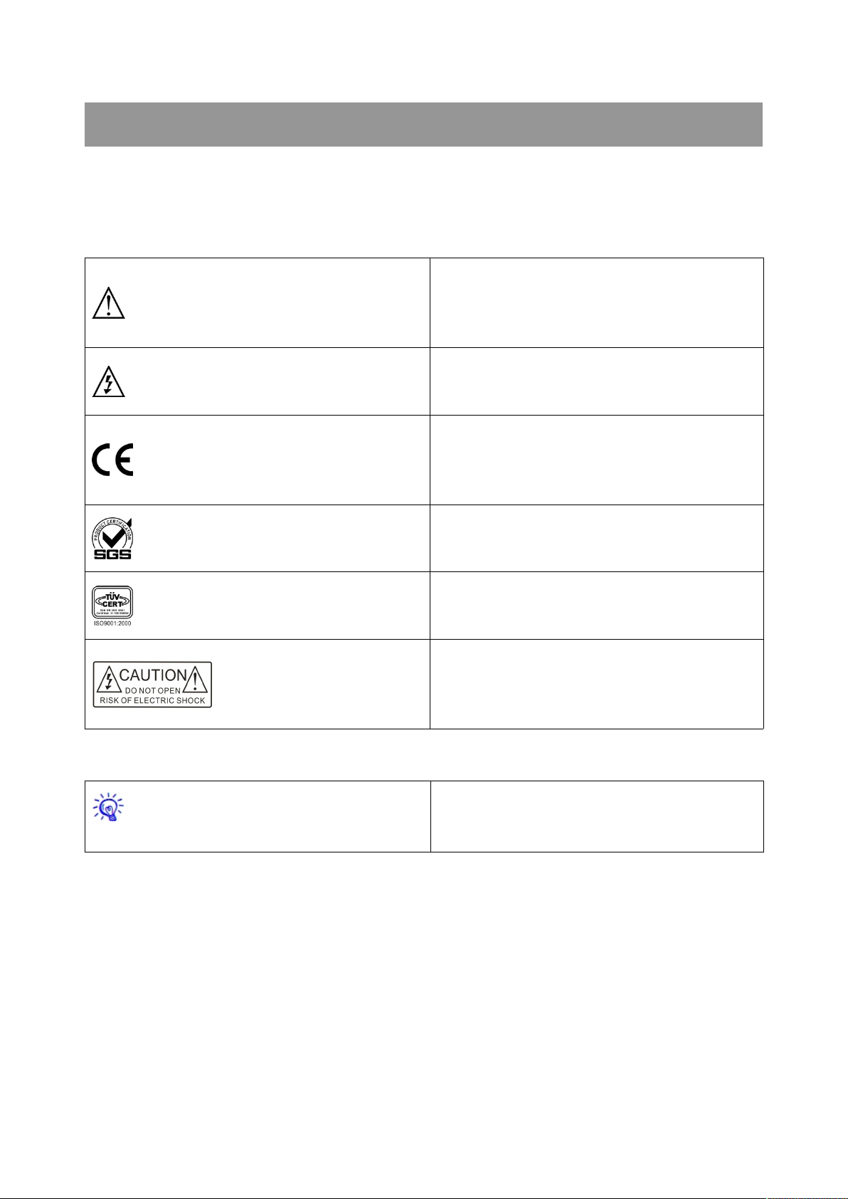
The meaning of symbols
This is A level product, which may cause radio
interference in the living environment. In this
case, users may need to take the feasible
measures to get around the interference.
CE certification means that the product has
reached the directive safety requirements
defined by the European Union. Users can be
assured about the use of it
Warning: in order to avoid electrical shock, do
not open the machine cover, nor is the useless
part allowed to be placed in the box. Please
contact the qualified service personnel.
■Safety instructions
For your safe and correct use of equipments, we use a lot of symbols on the equipments and in the
manuals, demonstrating the risk of body hurt or possible damage to property for the user or others.
Indications and their meanings are as follow. Please make sure to correctly understand these
instructions before reading the manual.
Remind users that the dangerous voltage
without insulation occurring within the
equipment may cause people suffer from shock
SGS certification means that the product has
reached the quality inspection standards
proposed by the world's largest SGS.
This product passed the ISO9001 international
quality certification (certification body: TUV
Rheinland, Germany).
■General information instructions
It lists the factors leading to the unsuccessful
operation or set and the relevant information to
pay attention to.
Page 3

Important note
Warning
In order to ensure the reliable performance of the
equipment and the safety of the user, please
observe the following matters during the process
of installation, use and maintenance:
The matters needing attention of installation
◆Please do not use this product in the following
places: the place of dust, soot and electric
conductivity dust, corrosive gas, combustible gas;
the place exposed to high temperature,
condensation, wind and rain; the occasion of
vibration and impact . Electric shock, fire, wrong
operation can lead to damage and deterioration
to the product, either;
◆In processing the screw holes and wiring,
make sure that metal scraps and wire head will
not fall into the shaft of controller, as it could
cause a fire, fault, or incorrect operation;
◆When the installation work is over, it should be
assured there is nothing on the ventilated face,
including packaging items like dust paper.
Otherwise this may cause a fire, fault, incorrect
operation for the cooling is not free;
◆Should avoid wiring and inserting cable plug in
charged state, otherwise it is easy to cause the
shock, or electrical damage;
◆The installation and wiring should be strong
and reliable, contact undesirable may lead to
false action;
◆For a serious interference in applications,
should choose shield cable as the high frequency
signal input or output cable, so as to improve the
anti-jamming ability of the system.
Attention in the wiring
◆Only after cutting down all external power
source, can install, wiring operation begin, or it
may cause electric shock or equipment damage;
◆This product grounds by the grounding
wires .To avoid electric shocks, grounding wires
and the earth must be linked together. Before the
connection of input or output terminal, please
make sure this product is correctly grounded;
◆Immediately remove all other things after the
wiring installation. Please cover the terminals of
the products cover before electrification so as to
avoid cause electric shock.
Matters needing attention during operation
and maintenance
◆Please do not touch terminals in a current
state, or it may cause a shock, incorrect
operation;
◆Please do cleaning and terminal tighten work
after turning off the power supply. These
operations can lead to electric shock in a current
state;
◆Please do the connection or dismantle work of
the communication signal cable , the expansion
module cable or control unit cable after turning
off the power supply, or it may cause damage to
the equipment, incorrect operation;
◆Please do not dismantle the equipment, avoid
damaging the internal electrical component;
◆Should be sure to read the manual, fully
confirm the safety, only after that can do program
changes, commissioning, start and stop
operation.
Matters needing attention in discarding
product
◆Electrolytic explosion: the burning of
electrolytic capacitor on circuit boards may lead
to explosion;
◆Please collect and process according to the
classification, do not put into life garbage;
◆Please process it as industrial waste, or
according to the local environmental protection
regulations.
Page 4

Preface
WIFI Conference System User 's Manual mainly introduces the operation methods of WiFi6201
conference controller, WiFi6202B chairman unit, WiFi6204B delegate unit, and CR-WF30 wireless AP
access device. It introduces their main performance parameters and common fault solutions as well.
This manual is only used as user instruction, not for a repair service usage. The functions or related
parameters may be changed since the date of issue, please inquire the supplemental information from
CREATOR Electronics or local distributors.
The copyright of this manual belongs to CREATOR Electronics. Without permission, no unit or
individual shall adopt part or all of its content for commercial use.
The manual is protected by of the Copyright Law of the Peoples Republic of China and other
regulations about intellectual property rights. Without written permission shall not be copied or
distributed.
Page 5

Catalog
Chapter 1 Summary.................................................................................................................................................. 1
1.1 Wireless Digital Network Conference System.....................................................................................1
1.2 System Features...................................................................................................................................... 1
1.3 System Equipment................................................................................................................................... 1
1.4 System Overview Diagram..................................................................................................................... 2
Chapter 2 WiFi Conference Controller................................................................................................................... 3
2.1 Product Overview..................................................................................................................................... 3
2.2 CR-WiFi6201 Panel Description............................................................................................................3
2.3 CR-WiFi6201 Function Characteristics................................................................................................ 4
2.4 CR-WiFi6201 Panel Key Operation...................................................................................................... 5
2.4.1 MENU Button Operation.............................................................................................................. 5
2.4.2 AFC Key Operation.......................................................................................................................6
2.4.3 ID Key Operation.......................................................................................................................... 6
2.5 The Method of Producing ETHERNET Line........................................................................................ 7
2.6 CONTROL SYSTEM COM Pin Function Description........................................................................ 7
2.7 AUDIO OUTPUTS 3.5mm Audio Interface Connection Description................................................7
2.8 CR-WiFi6201 Controller Installation......................................................................................................8
2.9 CR-WiFi6201 Technical Parameters.....................................................................................................8
Chapter 3 WiFi Conference Unit............................................................................................................................. 9
3.1 Product Overview..................................................................................................................................... 9
3.2 CR-WiFi6202/4B Panel Description......................................................................................................9
3.3 CR-WiFi6202/4B Function Characteristics........................................................................................ 10
3.4 CR-WiFi6202/4B Operating Instructions............................................................................................10
3.4.1 CR-WiFi6202/4B ID Setting......................................................................................................10
3.4.2 Using of CR-WiFi6202/4B.........................................................................................................10
3.5 CR-WiFi6202/4B Technical Parameters.............................................................................................11
Chapter 4 Wireless Access Point..........................................................................................................................12
4.1 Product Overview...................................................................................................................................12
4.2 CR-WF30 Panel Description................................................................................................................ 12
4.3 CR-WF30 Function Characteristics.................................................................................................... 13
4.4 Settings of CR-WF30............................................................................................................................ 13
4.4.1 Basic Settings..............................................................................................................................14
4.4.2 Advanced Settings......................................................................................................................16
4.4.3 Administration Settings.............................................................................................................. 17
4.4.4 Settings to Take Effect............................................................................................................... 17
4.5 Connection Diagram..............................................................................................................................17
4.6 Technical Parameters............................................................................................................................18
Chapter 5 System Settings.................................................................................................................................... 19
5.1 System ID Settings................................................................................................................................ 19
5.2 Automatic Camera Tracking Settings................................................................................................. 20
Chapter 6 System Connection Diagram.............................................................................................................. 22
6.1 Schematic Diagram of Single Wireless AP Access Device Application System Connection....22
Page 6

6.2 Schematic Diagram of Multiple Wireless AP Access Device Application System Connection. 23
Chapter 7 Accessories............................................................................................................................................24
7.1 Charging Box.......................................................................................................................................... 24
7.2 CR-P2 Headphones...............................................................................................................................24
7.3 CR-W6KL215B 215mm Heart-shaped Folding Rod Microphone Rod......................................... 25
7.4 CR-M4KL415 Knob Type 415mm Microphone Rod (Optional)......................................................25
7.5 CR-DOCK10B Wireless Conference Unit Charging Socket (Optional)........................................25
Chapter 8 Enclosure................................................................................................................................................26
8.1 CREATOR Conference System Protocol Code Formats and Their Descriptions.......................26
8.2 PELCO-D Camera Control Protocol Code Formats and Their Descriptions...............................27
8.3 PELCO-P Camera Control Protocol Code Formats and Their Descriptions............................... 27
8.4 VISCA Camera Control Protocol Code Formats and Their Descriptions..................................... 28
Page 7

1
WiFi Conference System User‘s Manual
Chapter 1 Summary
1.1 Wireless Digital Network
Conference System
Wireless conference system has gradually
become an important tendency of conference
system for its convenient installation and use, and
not subject to the restrictions of conference.
CREATOR takes the customer demand as goal,
independently researches and develops this
wireless digital network conference system.
Simple and intelligent design makes it more
convenient and flexible.
CREATOR wireless digital network conference
system is composed of controller, units and the
wireless access device. The conference unit
needs no wire connection. It can work as long as
being displayed in a corresponding position and
with simple setting.
Now, all kinds of conferences and seminars can
be held conveniently and flexibly no matter the
conference site is big or small.
1.2 System Features
◆No wiring, no drilling;
◆Cost saving
The WiFi conferencing system needs no second
decoration; it is simple to use;
◆Not limited by location, fast setting and
nondestructive to the venue
WiFi meeting system can be used right after
installation. No matter where you are going to use
the system, just put the equipment on the
conference table; and after the use, pack and
remove it.
◆No shelter, no interference
Using standard WiFi transmission technology, the
ability to penetrate, not affect the communications
equipment interference.
The conference audio is transmited to the
conference unit by 2.4G RF digital frequency
hopping technology. Audio broadcasting
transmission can effectively shorten the audio
transmission delay;
◆Built-in antenna
The built-in antenna design simplified the unit and
avoided the antenna broken or damage which
would influent the communication quality;
◆Comprehensive status indication function
Whether the device was dropped or entered the
working state, the unit will display device status
clearly.
◆Reliable Secrecy system
Support WPA/WPA2 wireless security technology,
so as to make sure the secrecy of meeting.
2.4G RF digital frequency hopping used the
unique ID code matching technology to keep the
meeting speech free from malicious
eavesdropping.
1.3 System Equipment
CREATOR wireless digital network conference
system mainly consists of the following
components:
◆CR-WiFi6201 wireless digital network
conference controller
◆CR-WiFi6202B wireless digital network
chairman unit
CREATOR CHINA 2013-09 WWW.CREATOR1997.COM
Page 8
2
WiFi Conference System User‘s Manual
◆CR-WiFi6204B wireless digital network
delegate unit
◆CR-WF30 wireless AP access device
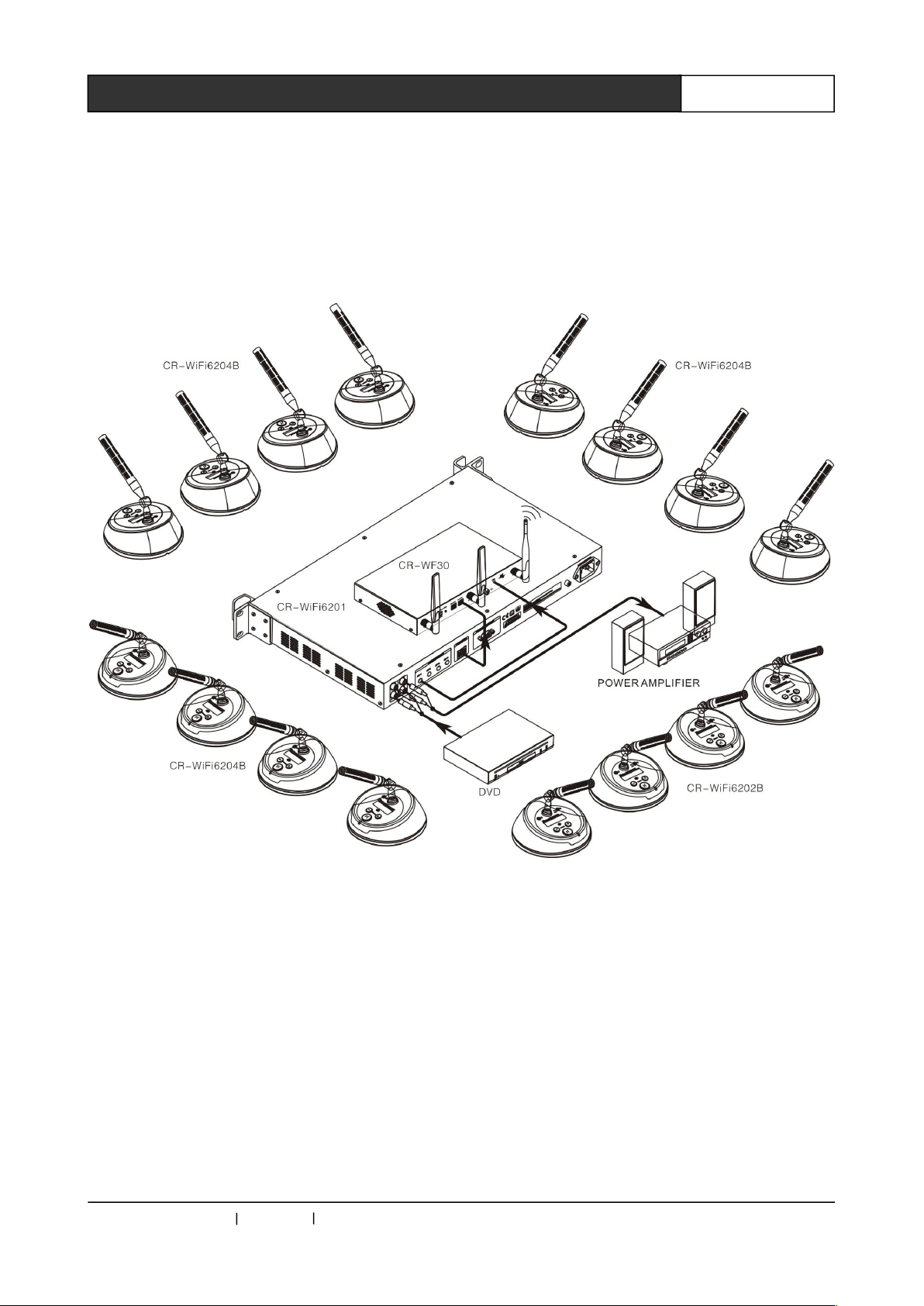
1.4 System Overview Diagram
CREATOR CHINA 2013-09 WWW.CREATOR1997.COM
Page 9
3
WiFi Conference System User‘s Manual
Chapter 2 WiFi Conference Controller
2.1 Product Overview
CR-WiFi6201 wireless digital network conference
host through the navigation button panel and with
LCD display can realize the centralized control of
all conference functions. It has a variety of
conference mode selection (the number of
speakers selection, speak mode selection). Audio
adopts digital DSP technology and environmental
noise suppression technology. With built-in
equalizer module, it can achieve high-fidelity
audio effects. The automatic camera tracking
control function is built in, the full automatic
tracking shot realize the modern high-tech
conference.
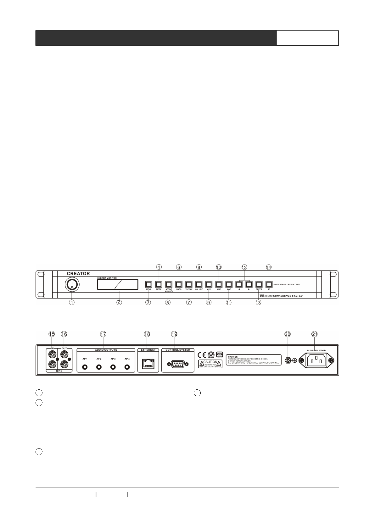
1 Power switch
2 LCD display screen
Display setting interfaces and parameters of the
menus of MIC MODE, MIC ACTIVE 'S, BASS,
TREBLE, VOLUME, SYSTEM ENQUIRY, ID
ENQUIRY and CAMERA.
3 MENU
The menu button, press this button to set the
menu options.
4 MODE
The microphone mode setting key has the
following two modes:
A: FIFO (FIFO mode), the first opened speech
unit was closed by the latest speech unit when
the units reach the setting number.
B: NORMAL (quantitative model), the new speech
unit is restricted to speak when the units reach
the setting number.
2.2 CR-WiFi6201 Panel Description
Front panel:
Rear panel:
CREATOR CHINA 2013-09 WWW.CREATOR1997.COM
Page 10
4
WiFi Conference System User‘s Manual
5 ACTIVE MICRO’S
The restriction on the number of speech units, the
number of speech units opening at the same time
can be 1/2/4/6.
6 BASS
Bass gain button, used for bass menu operation
settings.
7 TREBLE
Treble gain button, used for treble menu
operation settings.
8 VOLUME
Output volume adjustment button, press this
button for output volume menu settings.
9 AFC
Automatic frequency control button
10 ANC
Anti-noise key
11 AGC
Auto gain control button for Microphone
12 and
The left and right arrow keys: used to move the
cursor to determine the options in various
operating settings.
13 ENTER
Confirm key, used for confirming and performing
the operation in a variety of settings.
14 ID
ID setting key is used for global ID encoding
settings for all conference units in the system ID
setting.
15 IN
Audio input port, to connect the external device
for audio input, such as background music or
teleconference terminal output.
16 OUT
Audio output port, connected to a amplification
system to amplify and output the voice of the
speaker or record with recording equipment.
17 AUDIO OUTPUTS
4-way balanced audio output interface, used to
connect the AUDIO interface of the wireless AP
access device, provides audio and control signals
for RF audio channel of wireless AP access
device.
18 ETHERNET
The Ethernet control interface, used to connect
the wireless AP access device, can also be
connected to switches through the Ethernet
interface to expand the number of wireless AP
access device.
19 CONTROL SYSTEM
Can be connected to the third party central
control system controller, camera tracking
controller or be directly connected to the camera,
to realize the automatic camera tracking function.
20 Ground wire interface
21 System power input port
He controller power supply, support for
AC100~240V 50/60Hz.
2.3 CR-WiFi6201 Function
Characteristics
◆Support WPA/WPA2 wireless security
technology to ensure the conference
confidentiality and avoid eavesdropping and
malicious interference;
◆With a RJ45 interface, can be directly
connected to a wireless AP access device, or be
connected to the 100M network switches, then
connect wireless AP access device to the switch.
Expanding the number of wireless AP access
device can realize the application of the multiple
meetings;
◆A group of LINE In input interface can be
connected to an external audio device;
◆A set of microphone mixer output with recording
equipment can carry out on-site meeting
recording;
◆4 balanced audio output to the wireless AP
access device, to achieve long distance audio
transmission of 100M.
◆Support manual button to adjust the output
volume, bass, treble adjustment;
CREATOR CHINA 2013-09 WWW.CREATOR1997.COM
Page 11
5
WiFi Conference System User‘s Manual
◆Built-in DSP automatic frequency control button
function;
◆Support for automatic camera tracking function,
and a variety of control protocol of CREATOR,
PELCO-P/D, VISCA;
◆All-metal shell, circuit and outer shell
strengthened with wire connection, with the
contact 12kV, air 15kV antistatic ability;
◆The controller can be mounted on a standard
19 inch rack.
2.4 CR-WiFi6201 Panel Key
Operation
In order to facilitate the management and use,
CREATOR design the navigation panel and LCD
display, which is simple to operate and easy to
master.
Basic operating instructions
Function key Arrow keys “ENTER”
confirm key
Arrow keys “ENTER” to confirm
No operation for about ten seconds after the
completion of installation, the system will
automatically exit the setting interface.
LCD screen display
The LCD screen is in long bright state when the
controller is on, and displays the current system
state and operation information with white letters
on the blue backlight.
Key lamp description
Key lamp is in flashing red state, the red lamp
flash once, means the setting of key function or
parameter has been successful, and the LCD
screen will display the corresponding information.
2.4.1 MENU Button Operation
MENU button can do operation for MIC MODE,
MIC ACTIVE 'S, BASS, TREBLE, VOLUME,
SYSTEM ENQUIRY, ID ENQUIRY and CAMERA.
The basic steps are as follows:
1, Press the "MENU" button, LCD displays the
first option "MIC MODE";
2, Press the “ ” or “ ”" button to browse all
options, while the LCD screen display the current
operating state, then select the setting required
option, press "ENTER" to confirm;
3, Enter the option parameter setting interface,
Press the “ ” or “ ”" button to move the cursor
to select your setting required option;
4, Press "ENTER" button to confirm the
parameters set.
When you have not exit the setting
interface, press "MENU" button, the screen
will display the last operated option, instead
of displaying the first option.
For example
Set the microphone mode to NORMAL
(quantitative model), operation steps are as
follows:
1, Press the "MENU" key to enter the microphone
mode selection interface in the navigation panel,
while the key lamp was lit once, and LCD screen
has a corresponding display;
2, Press the “ ” or “ ” direction key to move left
or right, each time the direction key “ ” or “ ”
is pressed, the key lamp will be lit at the same
time; select the "MIC MODE" option, press
"ENTER" to confirm, the "ENTER" lamp be lit,
LCD screen displays the menu of microphone
mode settings;
3, Press the “ ” or “ ” direction key to move
cursor left or right, select "NORMAL" (quantitative
model), at the same time the button lamp is lit,
and LCD screen has a corresponding display.
4, Then press "ENTER" to confirm the operation
so as to complete the operation.
You can also directly press the microphone mode
setting key "MODE" on navigate panel to enter
the menu setting. Follow the third and fourth
steps to finish the operation with more
convenience. The operations of other keys on
navigation panel (including the ACTIVE MICRO
'S’, BASS, TREBLE, VOLUME) are of the same.
CREATOR CHINA 2013-09 WWW.CREATOR1997.COM
Page 12
6
WiFi Conference System User‘s Manual
2.4.1.1 SYSTEM ENQUIRY Menu
In the menu of MENU, press the “ ” or “ ”
direction key to select sub-menu "SYSTEM
ENQUIRY", then press "ENTER" button to enter
the system inquiry.
In the "SYSTEM ENQUIRY" menu, press the “ ”
or “ ” direction key to query the number of all
the conference units when the system was
constructed, and the number of conference units
to which wireless AP access device
correspondingly connected.
The queried information is the parameter
information when the system was constructed,
so as to facilitate the system setting and
maintenance, rather than that of the current
real-time connection status.
2.4.1.2 ID ENQUIRY Menu
In the menu of MENU, press the “ ” or “ ”
direction key to select sub-menu "ID ENQUIRY",
then press "ENTER" button to enter the ID inquiry.
Press the “ ” or “ ” direction key in the "ID
ENQUIRY" menu to query the assigned ID value
of each conference unit when the system was
constructed.
2.4.1.3 CAMERA Menu
In the menu of MENU, press the “ ” or “ ”
direction key to select the submenu "CAMERA",
then press "ENTER" key to enter the automatic
camera tracking settings.
In the "CAMERA" menu, press the “ ” or “ ”
direction key can choose "Protocol" and "Preset"
options. Then press "ENTER" key to enter the
corresponding settings.
You should first enter into the "Protocol" to select
the corresponding camera protocol. Support
CREATOR DEF (standard return code of
CREATOR conference system), PELCO-D,
PELCO-P and VISCA. The unified baud rate of
protocols is 9600bps.
After select the appropriate protocol, return to the
previous layer menu, enter "Preset" setting of
camera, and then bind the preset of the camera
with the unit ID to realize the camera tracking.
In the "Preset" menu, select "SET", then enter the
camera preset settings; select "CALL", then enter
the camera preset recall state.
For detailed operating, please refer to
camera preset setting procedures in the later
part.
2.4.2 AFC Key Operation
Automatic frequency control function setting:
press "AFC" button on the controller panel, so as
to start the automatic frequency control function,
at the same time the key lamp is lit up. Press
"AFC" button again, button lamp is off, and the
automatic frequency control function is closed.
The setting methods of "ANC" anti-noise function
and "AGC" microphone auto gain control function
are similar to "AFC" operation method.
2.4.3 ID Key Operation
ID key is used to control WIFI conference system
enter or exit ID setting function when the system
is under construction.
Long press "ID" key for 5 seconds, the ID key
indicator stay lit, LCD display "SYSTEM SETING",
suggest it has entered the ID setting function. In
this state, pressing the “ ” or “ ” direction key
can query the total number of meeting units of
currently set ID, and the number of meeting units
connected with the wireless AP access device.
Short press or long press the "ID" key, can exit
the ID setup and enter the normal working state.
For detailed operating, please refer to the
below ID setup instructions.
CREATOR CHINA 2013-09 WWW.CREATOR1997.COM
Page 13
7
WiFi Conference System User‘s Manual
2.5 The Method of Producing
ETHERNET Line
The system adopts the CAT-5 (super 5 cable) as
the wire. Install RJ45 connector (commonly
known as crystal head) at both ends of the CAT-5
to connect network devices. The standard
connection of twisted pair cable is not
predetermined. The purpose is to ensure the
symmetry of the layout of cable splice, so you can
make the interference between the joint inner
cables cancel each other. General UTP line has
four pairs of twisted thin line, and marked with
different colors.
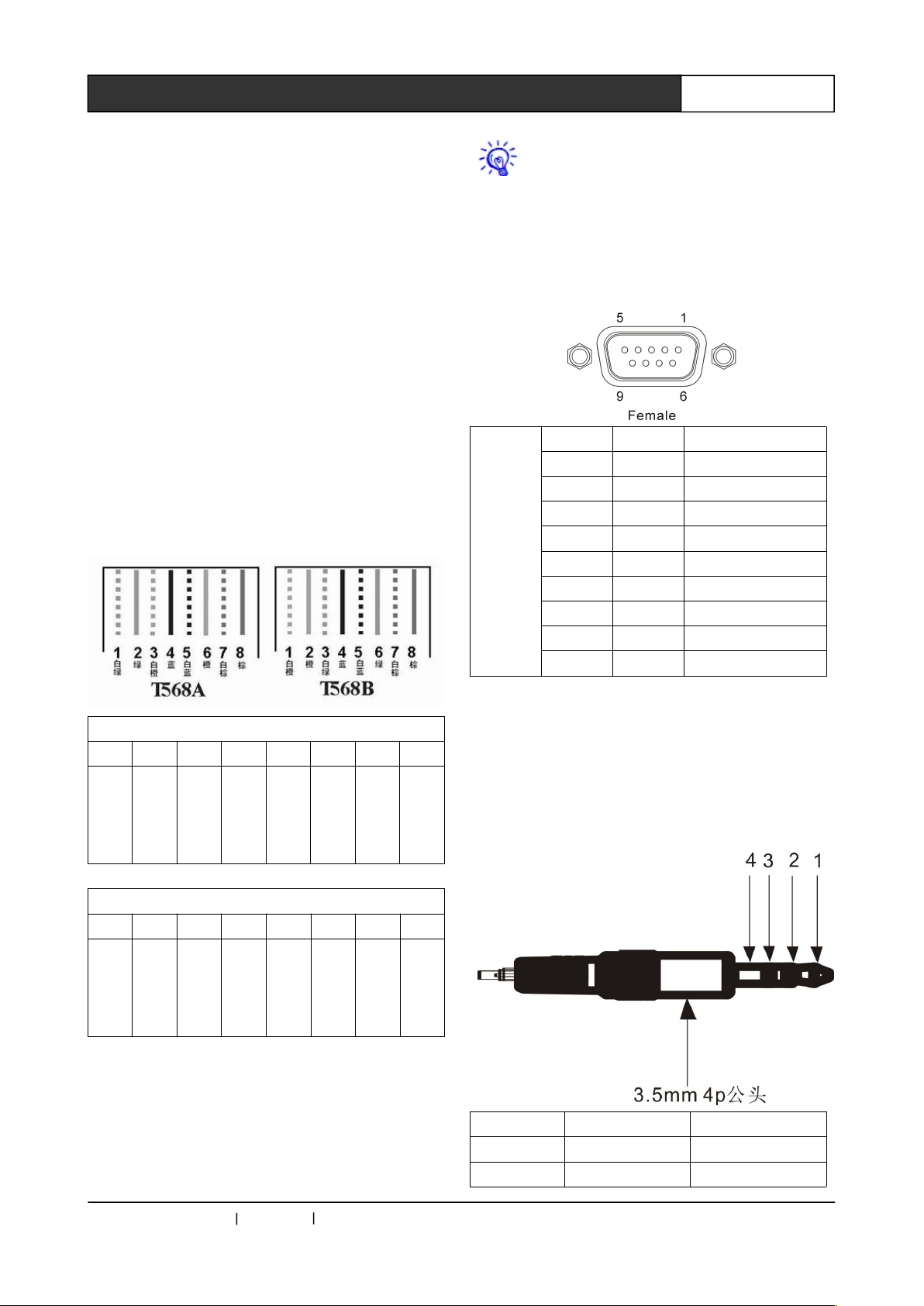
Twisted pair line has two configurations: EIA / TIA
568B standard and EIA / TIA 568A standard.
T568A linear order
1 2 3 4 5 6 7 8
whi
te
gre
en
gre
en
Wh
ite
ora
nge
blu
e
Wh
ite
blu
e
ora
nge
Wh
ite
bro
wn
bro
wn
T568B linear order
1 2 3 4 5 6 7 8
Wh
ite
ora
nge
ora
nge
Wh
ite
gre
en
blu
e
Wh
ite
blu
e
gre
en
Wh
ite
bro
wn
bro
wn
Direct line: two ends connected according to
T568B wire order standard.
Cross-line: One end connected according to
T568A line order, the other connected according
toT568B linear order standard.
Use cross-line to connect router and PC
2.6 CONTROL SYSTEM COM Pin
Function Description
Control
System
Pin Signal Description
1 — —
2 RXD Receive data
3 TXD Send data
4 — —
5 GND Signal ground
6 — —
7 — —
8 — —
9 — —
2.7 AUDIO OUTPUTS 3.5mm
Audio Interface Connection
Description
Pin Signal Description
1 AU+ Audio signal+
2 AU- Audio signal -
CREATOR CHINA 2013-09 WWW.CREATOR1997.COM
Page 14
8
WiFi Conference System User‘s Manual
3 SIG Control signal
4 GND Signal ground
AUDIO interface pin function of wireless
AP access device is same with this
description.
Connection wire between this interface and
the wireless AP access device should be the
audio wire with shielding layer, so as to
effectively guarantee the audio transmission
quality.
2.8 CR-WiFi6201 Controller
Installation
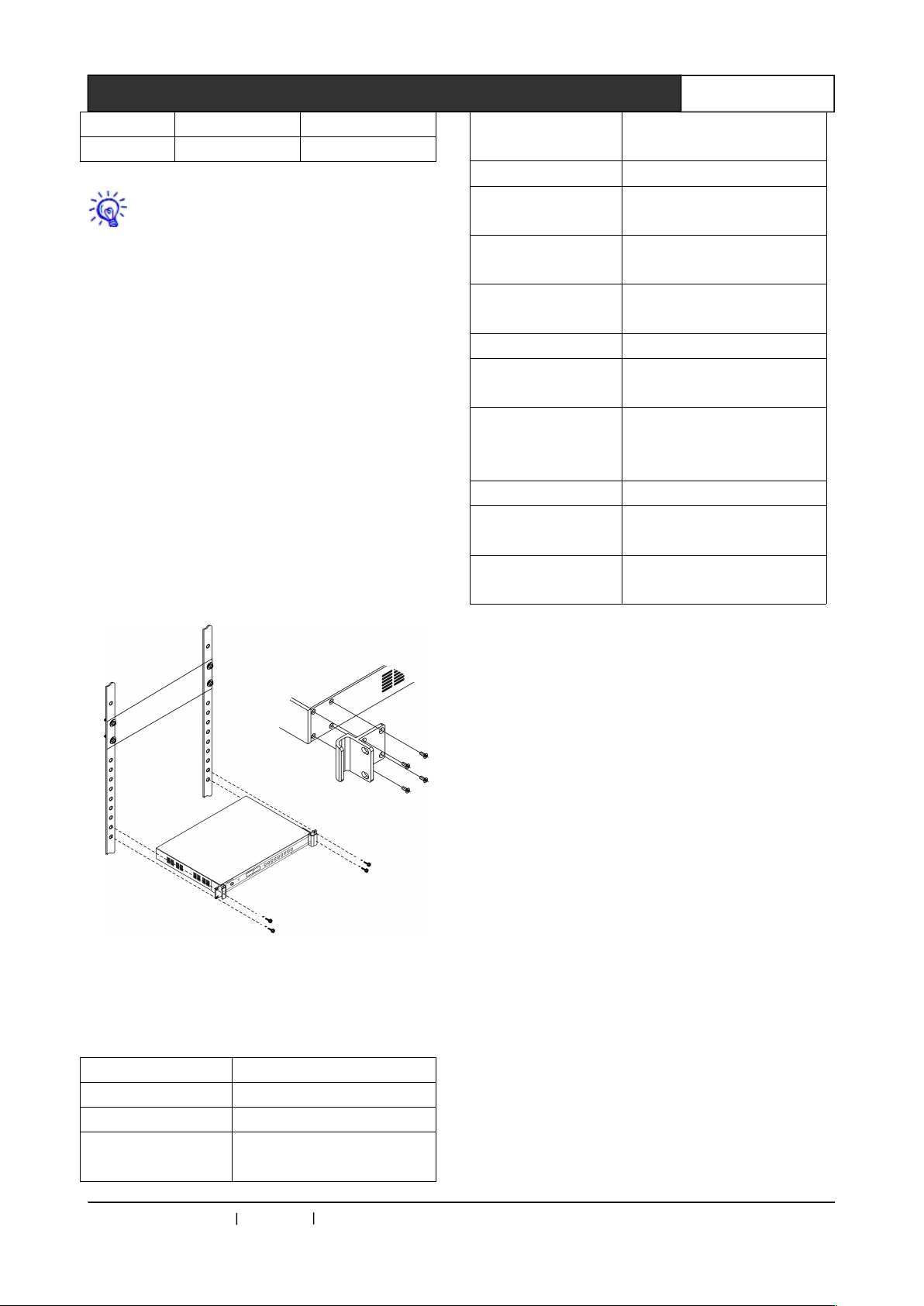
WiFi conference system controller can be
mounted in a standard 19 inch rack, the standard
controller accessories contain a pair of cabinet
mounting brackets , see below:
2.9 CR-WiFi6201 Technical
Parameters
Network interface RJ45 port
Control interface DB9 female port
Display 1602LCD displayer
Signal to noise
ratio(S/N)
>80dB
Harmonic
distortion
<0.5%
Carrier distortion <1%
Crosstalk
attenuation(1KHz)
>50dB
Static power
consumption
3W
Maximum power
dissipation
70W
Dynamic range >80dB
Frequency
response
20Hz~20KHz
communication
distance between
AP and controllert
<100m
Dimension 483LX290WX43.6H(mm)
Power supply
(America, Japan)
AC100V~AC120V 60Hz
Power supply
(Eurasia)
AC200V~AC240V 50Hz
CREATOR CHINA 2013-09 WWW.CREATOR1997.COM
Page 15
9
WiFi Conference System User‘s Manual
Chapter 3 WiFi Conference Unit
3.1 Product Overview
The CR-WiFi6202/4B wireless conference unit
adopts special design to ensure the machine is
stable, durable, and can fit any meeting room.
Using the built-in antenna design; each unit built
in with high performance battery which can
provide continuous speech as long as 9 hour in
length; 13 hours of standby time; all functions of
meeting unit can be completed with the unit panel
buttons; transmission uses WiFi encryption and
2.4G RF frequency hopping technology, adopting
only -ID code pairing reception speak, guarantee
no unauthorized interception.
3.2 CR-WiFi6202/4B Panel
Description
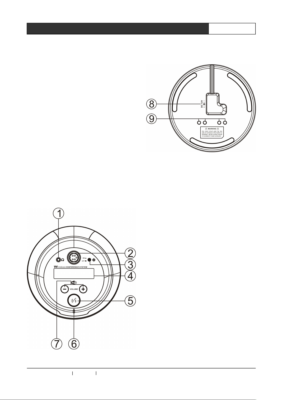
Top view:
Bottom view:
① The headphone jack, plug in headphones can
listen to the voice of the spokesman.
②The plug-in type microphone rod base
(microphone interface), with 5 core high density
air interface, with a screw knob type joint, making
the equipment connection more stable.
③The unit machine power button, press this
button to make the unit enter into the working
state, at the same time, the power indicator is lit.
④LCD display, blue backlight and white letters
display the related operating.
⑤The microphone switch button, press this
button, the MI pole red indicator will be lit.
⑥The power indicator
⑦The volume adjusting button, it can adjust the
volume of headphone and microphone
simultaneously.
⑧The input port of power, the system power
supplies DC 12V adaptive.
⑨Charging port of the unit, four ports charge
correspondingly with the box.
CREATOR CHINA 2013-09 WWW.CREATOR1997.COM
Page 16

10
WiFi Conference System User‘s Manual
3.3 CR-WiFi6202/4B Function
Characteristics
◆The DHCP settings, each conference unit with
an independent IP address;
◆WiFi transmission technology, strict digital
protection to ensure the privacy of the meeting, to
avoid malicious eavesdropping and jamming;
◆Capacitor heart type direction microphone, with
two colors indication lamp ring; speech is red,
when it is lack of electricity, the green light
flashing;
◆With a 3.5mm stereo headphone jack and the
volume control function;
◆The built-in speaker, with volume control
function;
◆LCD display with backlight, can display the
microphone on / off, ID settings and other
information;
◆Chairman unit is also affected by the largest
number of speakers’ restrictions;
◆Chairman unit has priority on closing speaking
units;
◆Built-in rechargeable lithium battery, battery
capacity to support 9 hours of continuous speech
or static standby 13 hours;
◆Using special 5 core high density airline
interface;
◆The professional meeting microphone, nut
knob type joint connecting, can freely swap;
◆The built-in loudspeaker;
◆Automatic frequency control function, when
microphone is turned on, the built-in loudspeaker
automatically shut down to prevent voice
reinfusion.
3.4 CR-WiFi6202/4B Operating
Instructions
3.4.1 CR-WiFi6202/4B ID Setting
Before the initial use of WIFI conference system,
the ID setting to all the meeting units is need to
make sure normal use. The specific ID setup
steps are as the following.
3.4.2 Using of CR-WiFi6202/4B
Once the ID is set for the first use, just press the
power switch of unit in the later use, unit LCD will
be lit and begin to work. When the unit is initialed,
it will automatically connect to the wireless AP
access device set in ID setting, and work normally
after then.
When in normal work, press the microphone
switch button, the red rod indicator is lit up. The
speaker can start speech.
In NORMAL mode, once the number of units with
opened microphone reaches the numerical value
set by ACTIVE MICRO'S, the later units cannot
open microphone any more.
In FIFO mode, once the number of units with
opened microphone reaches the numerical value
set by ACTIVE MICRO'S, the later unit which
opens microphone will take the place of the first
unit with opened microphone, on and on. The
microphone opened by chairman machine cannot
be taken over.
Long press the chairman machine microphone
switch button can turn off the opened
representative microphone in priority.
Volume control button can adjust the volume of
headphones and loudspeakers simultaneously.
Press the volume increase and decrease keys at
the same time, can see the unit IP and the
connected wireless AP access device.
The unit machine needs to work in the
range of 30 m around the wireless AP access
to ensure the good wireless signal
connection.
CREATOR CHINA 2013-09 WWW.CREATOR1997.COM
Page 17
11
WiFi Conference System User‘s Manual
3.5 CR-WiFi6202/4B Technical
Parameters
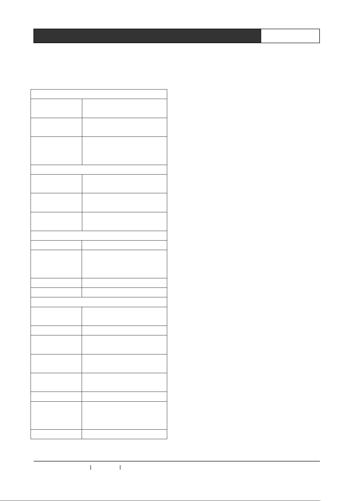
Connected components
Bottom
Used for pluggable
microphone socket
Earphone jack
One 3.5mm (0.14 inches)
stereo headphone jack
Power supply
The DC input power supply
(can access after removing
the battery group)
Electrical parameters
Frequency
response
30Hz~20kHz
Earphone
impedance
>32Ω <1KΩ
Output power of
loudspeaker
2×15mW/32Ω
Wireless parameters
Standard IEEE Draft 2.0 802.11n
Radio
frequency
range
4.900-5.850GHz
Transmit power 15dBm
Antenna gain 2dBi
Specifications
Output voltage
of the battery
7.2V
Battery capacity 3200mAH
Continuous
speech time
9 hours
Static standby
time
13 hours
Longest
charging time
3 hours
Color Black
Maximum
power
dissipation
2.6W
Dimension Φ=165 H=64 (mm)
CREATOR CHINA 2013-09 WWW.CREATOR1997.COM
Page 18
12
WiFi Conference System User‘s Manual
Chapter 4 Wireless Access Point
CR-WF30 wireless access point is a router for
wireless network.
The wireless access point is used for
communication connection between the wireless
conference unit and network control host,
providing convenient, flexible and reliable
conference environment based on wireless
network.
4.1 Product Overview
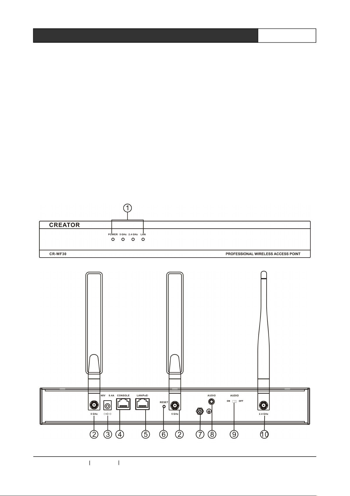
4.2 CR-WF30 Panel Description
Side view 1:
Side view 2:
CREATOR CHINA 2013-09 WWW.CREATOR1997.COM
Page 19

13
WiFi Conference System User‘s Manual
① POWER
The power indicator: the power indicator lights up
when it is normally powered, in reverse, the
indicator won’t be lit.
5GHz
5GHz wireless network signal indicator, when the
5GHz wireless network signal is passing through,
the light flashes, suggests it is sending or
receiving signal.
2.4GHz
2.4GHz RF wireless digital audio signal indicator,
when the 2.4GHz RF wireless digital audio is
opened, the indicator is lit and flashes.
LAN
Ethernet signal indicator, when the Ethernet
signal is passing through, indicator is lit, says it is
sending or receiving signal.
② 5GHz antenna
Provide a pair of 5GHz free rotation antenna to
adjust the best sending or receiving range.
③ DC 48V
The DC power input port, the controller supports
DC 48V power input.
④ CONSOLE
The control port, preserved
⑤ LAN(PoE)
Ethernet port, used to connect the WIFI
conference controller or network switcher.
⑥ RESET
The reset button, press the reset button for about
10 seconds, the access device would be reset to
factory default configuration.
The reset button will remove all settings
and return to the default value, including all
the wireless security and the IP address. The
reset IP address is 192.168.0.50, user name:
admin, password is empty.
⑦ Ground wire interface
⑧ AUDIO
Balanced audio input port, used to connect the
conference controller.
⑨ AUDIO ON/OFF
AUDIO ON/OFF is used to open or close the 2.4G
RF wireless digital audio of the wireless AP
access point.
⑩ 2.4GHz antenna
Provide a pair of 2.4GHz free rotating antenna for
adjusting the best sending scope of RF wireless
digital audio.
4.3 CR-WF30 Function
Characteristics
◆WiFi signal transmission using WPA/WPA2
digital encryption technology ensures the
conference confidentiality and avoids
eavesdropping and malicious interference;
◆With a RJ45 interface, it can be connected to
the CR-WiFi6201 host or switch interface.
Connecting cable recommended the use of high
quality CAT5 cross cable;
◆With a 4 road 3.5mm interface, can be
connected to the CR-WiFi6201 host, providing 1
balanced audio and control signal input;
◆In the open area, in the case of weak
interference, the circular signal coverage area
can reach a radius of 30 meters and the general
coverage area can reach a radius of 25 meters;
◆According to IEEE802.1 1n WIFI network
standard;
◆The three antenna design makes the data
transmission more stable.
4.4 Settings of CR-WF30
Step 1
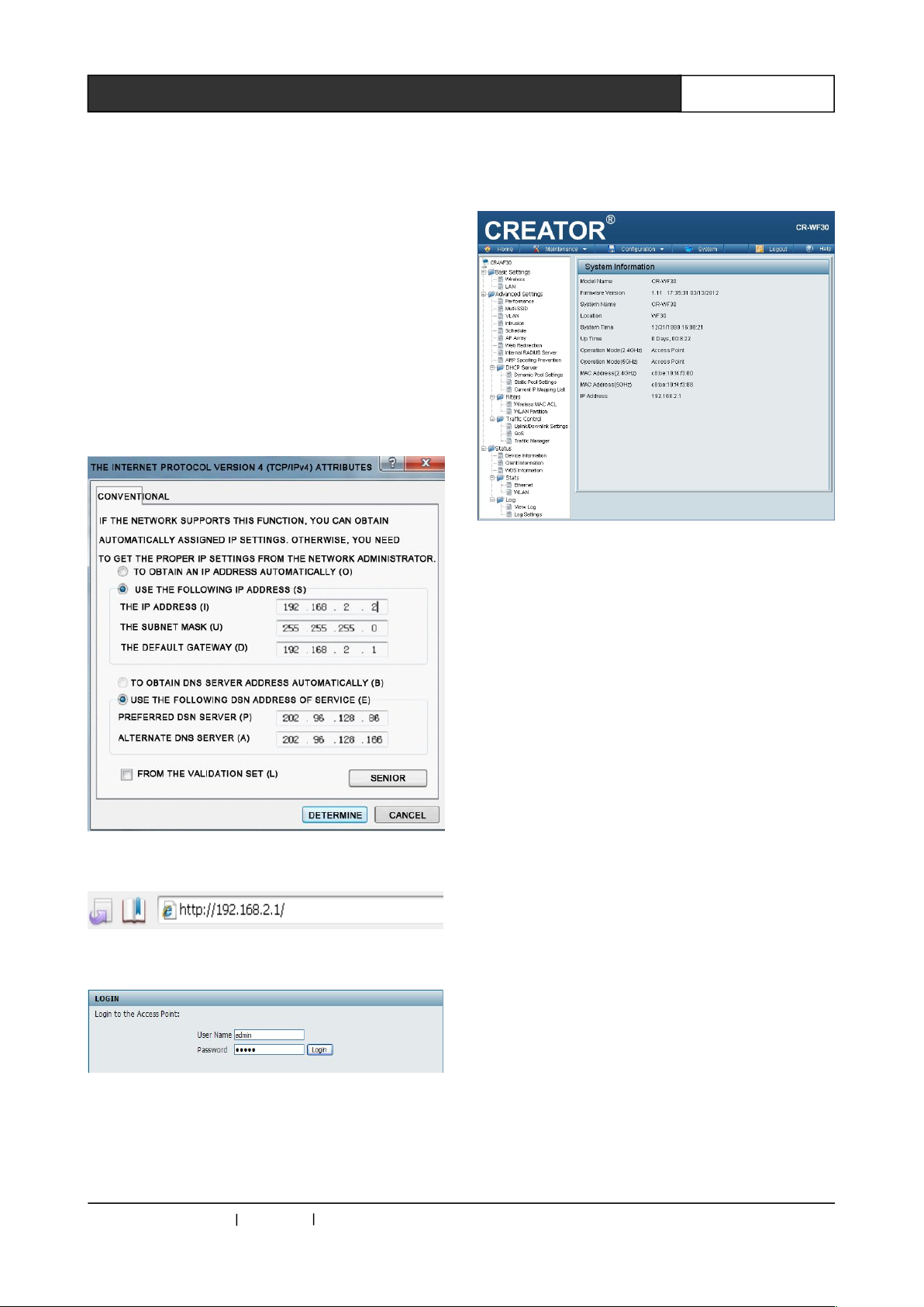
Connect the LAN (PoE) port of CR-WF30 and
computer with cable, and set the IP of computer
cable network to the same network segment as
the router, for instance: the router IP is
192.168.2.1 (default),then the computer IP should
be set to 192.168.2. (0~255).
First open the "local area connection" in the
CREATOR CHINA 2013-09 WWW.CREATOR1997.COM
Page 20
14
WiFi Conference System User‘s Manual
"network neighborhood", pops up "local
connection" dialog box, select "Internet protocol
(TCP/IP)", and click " attributes " to enter the IP
setting interface "Internet protocol TCP/IP)
attributes". As shown in figure 4-1.
Step 2
When the setup is completed, open IE browser,
input the 192.168.2.1 in the address bar and
press the Enter key, as shown in figure 4-2. If the
connection IP is normal, router login dialog box
will pop up, enter the user name: admin (default)
Password: admin (default) in the dialog box,
press Enter to confirm, as shown in figure 4-3.
Figure 4-1
Figure 4-2
Figure 4-3
Step 3
Enter the first page of CR-WF30 setup interface,
display as below, main setting items including
Basic Settings, Advanced Settings and
administration Settings under Maintenance menu.
Figure 4-4
4.4.1 Basic Settings
In Basic Settings options, system settings can be
divided into the Wireless setting and LAN setting.
(As shown in Figure 4-4)
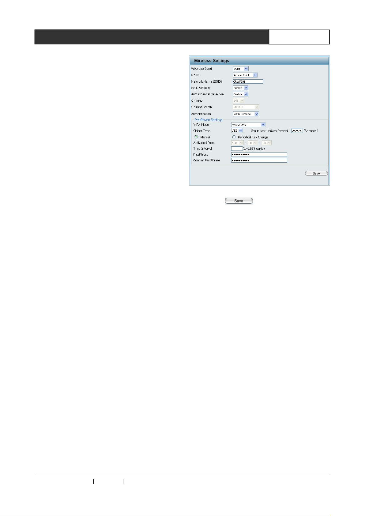
◆ Wireless
Wireless setting is used to set the wireless
frequency, wireless mode, wireless name (SSID),
wireless channel and wireless password.
Wireless Band:
2.4GHz or 5GHz band is optional. 5GHz band
should be chosen in WIFI conference system.
Mode:Wireless mode, select Access point
Network Name (SSID): SSID name, the name of
this AP can be seen in all wireless network shared
by all equipment. In the application of WIFI
conference system, SSID should be fixed to any
value from"CRWF301" to "CRWF30F".
SSID Visibility:
SSID name can be visible or invisible, for
convenient connection, please set "enable".
Auto Channel Selection:
Whether automatically choose the wireless
channel. If you choose "Disable", select an
interference free channel in the next option; when
you are not sure whether the channel is with
CREATOR CHINA 2013-09 WWW.CREATOR1997.COM
Page 21
15
WiFi Conference System User‘s Manual
interference or not, select "Auto".
Channel:
Channel selection, you should select the channel
with no or little interference in current network,
otherwise it is easy to cause interference to the
WIFI conference system.
Channel Width:
Occupied channel width, which directly affect the
network maximum transmission rate. Select
"20MHz", the maximum transmission rate is
150Mbps, select "40MHz", the maximum
transmission rate is 300Mbps, you are
recommended to choose "Auto 20/40 MHz".
Authentication:
Authentication: password authentication type. In
order to ensure data security, WIFI conference
system’s fixed password authentication type is
"WPA-personal".
WPA Mode:
WPA is a WLAN security enhancement solution
which is based on standard. It is interoperable,
can greatly enhance the data protection and
access control level of existing and future
wireless LAN systems. In order to improve the
security levels of data, WIFI conference system
fixed the option as "WPA2 Only".
Cipher Type:Password type is fixed "AES"”
Group Key Update Interval:
AES/TKIP password update interval. The fixed
password is "AES" in the former setting, this
setting does not work, just keep the default value.
Choose password update to "Manual", custom.
Pass Phrase:
Wireless password, the password required for the
unit terminal to change AP through wireless
connection. It should be fixed to "9999999999",
10 "9"s.
Confirm Pass Phrase:
Confirm the password. Input the former
password again.
So far Wireless Settings are completed. As
shown below:
Figure 4-5
Click on the button to save the
setting.
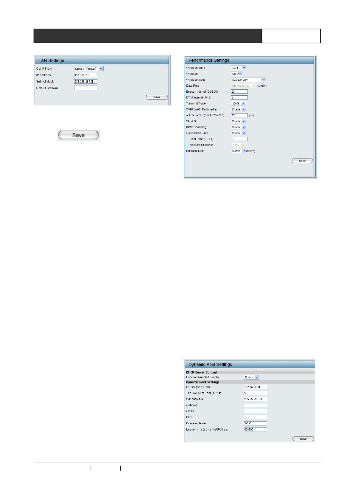
◆ LAN:
Network setting: set the IP address in the setting
options of this column.
LAN Settings:
Select the fixed IP address (the default), if you
want to assign a static IP address or a fixed
address, you have to complete the following
matters.
Select "Static IP (manual)" option in "Get IP
From" menu, set as follows:
Local IP Address:The local IP address, in the
same network the IP address must be the one
and only, the system default IP address is
196.168.2.1.
Subnet Mask:
Subnet mask, the subnet masks in the same
network must be identical, the system default is
255.255.255.0.
Default Gateway: can leave blank, without
setting.
As shown below::
CREATOR CHINA 2013-09 WWW.CREATOR1997.COM
Page 22
16
WiFi Conference System User‘s Manual
Figure 4-6
Click the button to save, this
setup is completed.
4.4.2 Advanced Settings
Advanced settings: In WiFi conference system,
users only need to set the Performance option, as
well as Dynamic Pool Settings option under
DHCP Server, other options stay factory default
settings, no need to change.
4.4.2.1 Performance Settings
In WIFI wireless conference system, the AP
should set as working in 5GHz wireless band.
◆ The configuration of 5GHz wireless band
As far as 5GHz wireless band configuration is
concerned, WIFI conference system only need to
configure the following options, other options
remain the default value.
Wireless band: Wireless AP band selection;
select "5GHz".
Wireless: Please choose "On" to open the
wireless 5GHz band.
Wireless Mode:Please choose "802.11n Only"
mode, the wireless data transmission speed is up
to 300Mbps.
Beacon Interval (25-500): Choose the minimum
value "25" as the beacon Interval. This option will
affect the output audio quality of WIFI conference
system, please make sure it is set to the minimum
value.
WMM (Wi-Fi Multimedia):Recommended to be
set as disable
Till now the Performance setup is completed,
as shown below:
Figure 4-7
Click the "Save" button to save the setting.
After open the AP 5GHz band, you should close
the AP 2.4GHz band, make AP worke alone in the
band of 5GHz, as follows:
Wireless band:“2.4GHz”.
Wireless:Select "off" to close the 2.4GHz
wireless band. So far 2.4GHz band has been
closed, the following options are unworkable, you
can keep the default values. Click the "Save"
button in the lower right corner to save.
4.4.2.2 Dynamic Pool Settings
In WIFI conference system, wireless AP access
device allocate IP to each unit by DHCP. With
"Advanced Settings" - > "DHCP Server" - >
"Dynamic Pool Setting" menu, enable the
CR-WF30 DHCP functions, settings as shown
below:
Figure 4-8
CREATOR CHINA 2013-09 WWW.CREATOR1997.COM
Page 23
17
WiFi Conference System User‘s Manual
After the completion of setting, click the "Save"
button in the lower right corner to save.
IP Assigned Form must be
“192.168.2.*”,and "*" > 30 , Lease Time >
100000.
When multiple CR-WF30 wireless AP
access device are used in the system
simultaneously, the IP settings of DHCP
cannot overlap.
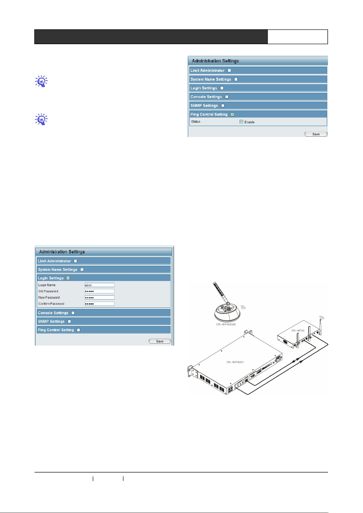
4.4.3 Administration Settings
This interface can be opened in Administration
Settings below the main menu Maintenance.
Administration is about management setting
options, it includes Limit Administrator, System
Name Settings, Login Settings, Console Settings,
SNMP Settings and Ping Control Setting. As
shown below:
Figure 4-9
Login Settings:You can reset the user name and
password, CREATOR recommends that you use
the default username and password, which are
convenient for subsequent maintenance.
Figure 4-10
Ping Control Setting: For the user of WIFI
conference system: in order to ensure the normal
communication between routing and controller,
please be sure to hook the “enable”. Click the
"Save" button to save the setting.
4.4.4 Settings to Take Effect
When all the settings are completed and saved,
click the "Save and Activate" in the main menu
"Configuration", router’s automatically restart is
finished, settings can enter into force by then.
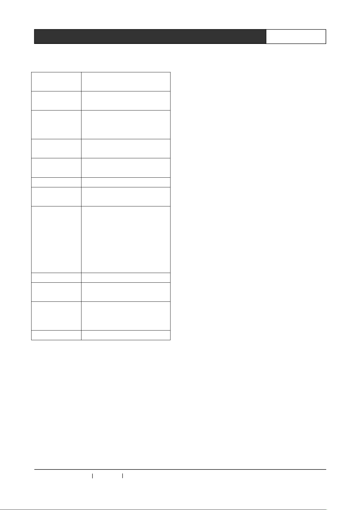
4.5 Connection Diagram
CREATOR CHINA 2013-09 WWW.CREATOR1997.COM
Page 24
18
WiFi Conference System User‘s Manual
4.6 Technical Parameters
Network
standards
IEEE Draft 2.0 802.11n
Network
interface
10/100Base-T
Radio
frequency
range
5GHz(Chinese
standard:5.725GHz to
5.85GHz)
Data transfer
rate
A maximum of 300 Mbps
Transmit
power
802.11N:17dBm
Antenna 2.4G:3dBi, 5G:5dBi
Connection
unit number
In the AP signal range, single
AP connect up to 50
Signal
coverage area
In the open area, in the case
of weak interference, the
circular signal coverage area
can reach a radius of 30
meters and the general
coverage area can reach a
radius of 25 meters;
Power supply DC48V
Working
temperature
0℃~40℃
Maximum
power
dissipation
19W
Dimension 324L×203.7W×43.6H(mm)
CREATOR CHINA 2013-09 WWW.CREATOR1997.COM
Page 25
19
WiFi Conference System User‘s Manual
Chapter 5 System Settings
5.1 System ID Settings
At the first time, the WIFI conferencing system ID
setting is needed before normal use. Systematic
ID setting can automatically allot IP, ID to each
unit, and finish the pairing operation of each unit
and RF wireless digital audio of AP. Specific steps
are as follows:
Step 1, wireless AP access settings
Before the system ID setting, you should set up a
wireless AP access device according to the
specific requirements. The setting of Wireless AP
access device should in line with the related
instructions.
SSID setting value of Wireless AP access
device should be within the range from
"CRWF301" to "CRWF30F".
When multiple APs connect through
network switches, the IP DHCP setting range
of each AP cannot overlap.
When multiple APs are used in the
system, in a radius of 30 meters work scope,
with the AUDIO ON/OFF switch, only one AP’s
RF wireless digital audio be opened, the
others’ should be closed.
Step 2 System connecting
Connect the WIFI conference system with its
functional interfaces. And then power the system.
Step 3 Enter the setting state
1, long press the "ID" button on WIFI conference
controller front panel for 5 seconds, "ID" key
indicator stay bright, which suggests that has
entered the system ID setting state. At the same
time, the 2.4GHz indicator of wireless AP access
device flashes at 0.5 second intervals.
2, when WIFI conference controller enter into the
ID setting state, if the unit has connected to the
controller, it can directly enter into the system ID
setting status, and the green indicator of MI rod is
lit. If the unit has not connected to the controller,
then you need to open the power switch of the
unit and press the microphone on/off key
simultaneously, until enter into the ID setting
status, and rod green indicator is lit.
According to this method, one by one to confirm
all the units have entered into the system ID
setting status.
Step4, performing setting operations
1, Press the volume increasing or decreasing key
on SSID selection interface of the unit , so as to
select the corresponding SSID of wireless AP
access device to which the unit is connected to.
Press the microphone switch key for confirmation,
and then the unit began to search for a wireless
AP access device, with rod red indicator lit.
2, if the search is failed, or it cannot connect to
the corresponding wireless AP access device, it
will return to SSID selection interface, with
microphone rod green indicator lit.
If it is connected to the corresponding wireless AP
access device, then it can be assigned IP, MI rod
red indicator extinguished, and it automatically
start RF pairing operation with RF wireless digital
audio sender.
If RF pairing is successful, then the unit
loudspeakers issue a long continuous "Du ~ ~ ~";
If RF pairing is failed, then the unit loudspeakers
issue continuous short "Du Du Du ~ ~ ~".
If the pairing is not successful, then click the
microphone switch key once again to reform a
pairing operation, until the pairing is succeeded.
3, According to the above method, finish all the
units’ settings one by one.
CREATOR CHINA 2013-09 WWW.CREATOR1997.COM
Page 26

20
WiFi Conference System User‘s Manual
Here you must make sure the unit
loudspeakers issue a long continuous "Du ~ ~
~"before proceeding to the next unit operation,
so as to avoid setting error which increases
the workload.
Step5 Complete the system ID setting
After the completion of the system settings of all
units, click the "ID" button on WIFI conference
controller front panel, then you can complete and
exit system setup.
The unit machine automatically exits the system
settings, and began to work normally.
5.2 Automatic Camera Tracking
Settings
WIFI conference system controller supports
automatic camera tracking function. It supports
CREATOR conference system standard protocol,
camera protocol of PELCO-D, PELCO-P and
VISCA as well.
The automatic camera tracking settings must be
done after completing the system ID setting of
WIFI conference unit. Otherwise is invalid. The
specific steps are as follows:
Step1,System connecting
Connected to CREATOR camera tracking
controller, or third party controller through RS-232
interface, WIFI conference controller can realize
control. It can directly connect to camera to
control.
WIFI conference controller fixed the baud rate of
RS-232 as 9600bps, the settings of camera or the
third party equipment shall be consistent with this.
When WIFI conference controller directly
connects to the camera, it can only control one
camera.
Step2, Control protocol selection
Select "CAMERA" on the WIFI conference
controller front panel MENU, press "ENTER" to
enter, and select the "Protocol" option, and then
press the "ENTER" you can enter control protocol
setting.
The system supports 4 types of control protocols,
respectively:
1) CREATOR DEF.: CREATOR conference
system standard protocol, which is used together
with the CREATOR camera tracking controller or
the third party controller.
2) PELCO-D: PELCO-D protocol; returns only to
two control codes, namely, the camera preset
spot setting and camera preset spot recall,
supports 128 preset spots, the camera address is
1.
3) PELCO-P: PELCO-P c; returns only to two
control codes, namely, the camera preset spot
setting and camera preset spot recall, supports
128 preset spots, the camera address is 1.
4) VISCA: SONY VISCA camera protocol.
Camera address is 1, the preset has been
extended to 128.
Step3, Enter the preset settings
Select the corresponding control protocol, press
"MENU" button to return to the previous menu,
select "Preset" option with the direction key “ ”
or “ ”, press "ENTER" to enter the Preset
interface.
Select "Set" with the direction key “ ” or “ ”,
press "ENTER" to enter into the preset settings.
When you have selected the CREATOR
DEF protocol, Preset setting is invalid. Go to
the related description of camera tracking
controller for its related operation.
Step4, Performing preset settings
Enter the preset setting state, set the WIFI
conference controller to FIFO mode, the
maximum number of microphones is 1.
Switch the camera footage to the first unit through
the camera remote controller, and adjust the
angle or magnification, and then press the
microphone power switch to open the unit, the red
indicator of the rod is lit, and then close the
CREATOR CHINA 2013-09 WWW.CREATOR1997.COM
Page 27

21
WiFi Conference System User‘s Manual
microphone, the preset setting of the unit is
completed.
Complete the preset settings of other units
according to this method.
When it comes to the preset setting of the last unit,
first adjust the camera angle and amplification,
and then press the microphone power switch to
open the unit, the red indicator of the rod is lit.
The preset setting of the unit is completed. Here
you should not close the microphone for the time
being. Adjust camera’s panoramic picture, then
close the microphone. The preset setting of
panoramic picture is finished.
Step5, Exit preset settings
Enter the Preset interface of WIFI conference
controller, select "CALL" option, press "ENTER"
to confirm, then you are out of the preset settings,
and can achieve normal camera tracking function.
CREATOR CHINA 2013-09 WWW.CREATOR1997.COM
Page 28
22
WiFi Conference System User‘s Manual
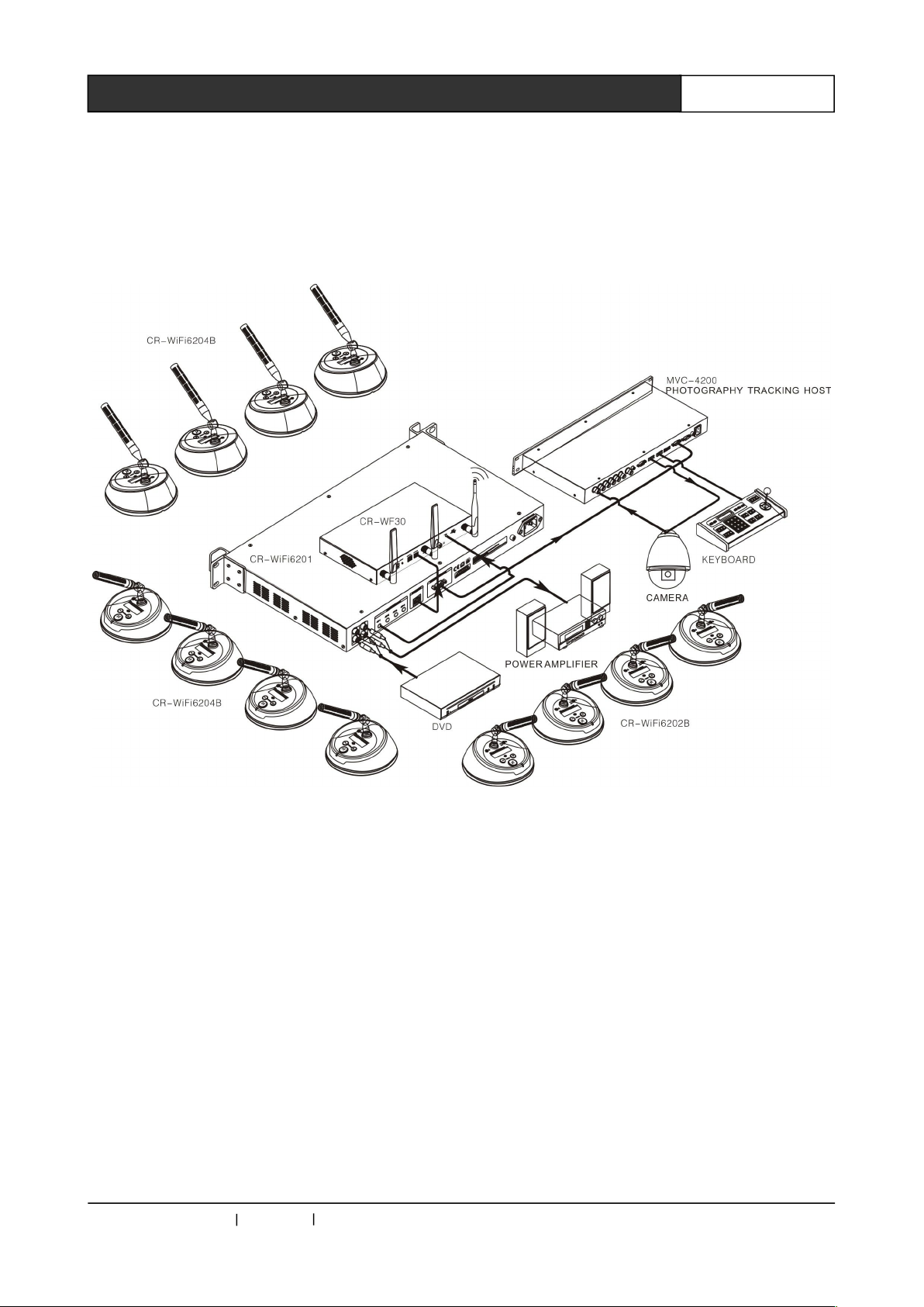
Chapter 6 System Connection Diagram
6.1 Schematic Diagram of Single Wireless AP Access Device
Application System Connection
CREATOR CHINA 2013-09 WWW.CREATOR1997.COM
Page 29
23
WiFi Conference System User‘s Manual
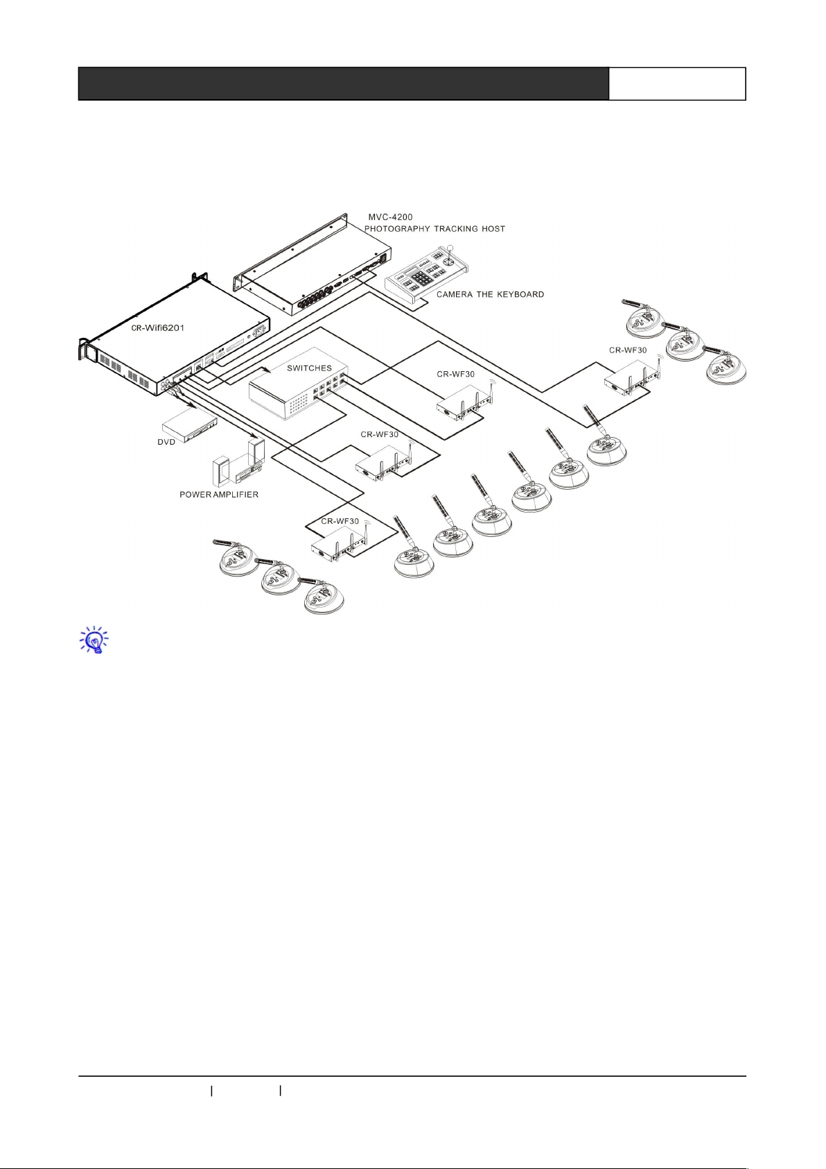
6.2 Schematic Diagram of Multiple Wireless AP Access Device
Application System Connection
When multiple wireless AP access device are used at the same time, must pay attention to
the following matters:
1, When set up wireless AP access device, you need to set each AP with different SSID, and stagger the
5G signal channels used by each AP;
2, with the AUDIO ON/OFF switch of wireless AP access device, make sure that 2.4G RF audio
frequency of different wireless AP access device do not interfere with each other in launching.
CREATOR CHINA 2013-09 WWW.CREATOR1997.COM
Page 30
24
WiFi Conference System User‘s Manual
Chapter 7 Accessories
7.1 Charging Box
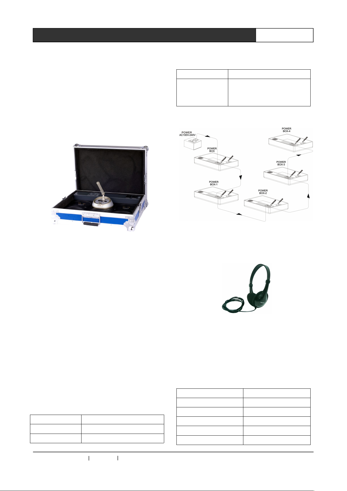
The WiFi conferencing system unit charging box
CR-WFDS06 is used for charging function.To
charge the 6 units at the same time, the power
input is connected in series; fast charging, the
longest charging time is 3 hours.
Charging diagram:
Function Characteristics
◆Can charge for the 6 units
◆Universal power supply;
◆The power input has the function of being
connected in series;
◆Fast charging: the longest charging time is 3
hours;
◆The charging box also has the function of
storage unit.
Controls and indicators
◆Turn on/off;
◆Charging status indicator
Interconnection
◆Serial interface of mains power supply: the
European type, male socket;
◆ 24 charging contacts
Technical Parameters
Dimension 497LX397WX120H(mm)
Weight About 5kg
Power 100W
consumption
Power
consumption
(standby)
3W
Charging box series connection diagram
7.2 CR-P2 Headphones
Function Description
◆It can be used in conference units for
monitoring;
◆Used in the conference system can avoid the
influences from other people;
◆ It comes with 1.5 meters long line;
◆ High fidelity sound quality.
Technical Parameters
Unit interface 3.5mm mono plug
Frequency response 30Hz -16KHz
Sensitivity 90dB
Signal to noise ratio > 80dB
Distortion < 0.1dB
Impedance 32 Ω
CREATOR CHINA 2013-09 WWW.CREATOR1997.COM
Page 31
25
WiFi Conference System User‘s Manual
Dynamic range > 85 dB
7.3 CR-W6KL215B 215mm
Heart-shaped Folding Rod
Microphone Rod
Function description
◆ Cardioid condenser microphone
◆ High density 5 core air interface;
◆ Normal speech indicator
◆Speech application indicator.
7.4 CR-M4KL415 Knob Type
415mm Microphone Rod
(Optional)
Function description
◆Cardioid condenser microphone;
◆ High density 5 core air interface;
◆ Normal speech indicator;
◆Speech application indicator.
7.5 CR-DOCK10B Wireless
Conference Unit Charging Socket
(Optional)
Function description
◆ Used by wireless conference speech unit for
power charge;
◆ With 4 anti-skid pads, can be fixed on the
desktop for charging while working;
◆ The charge indicator.
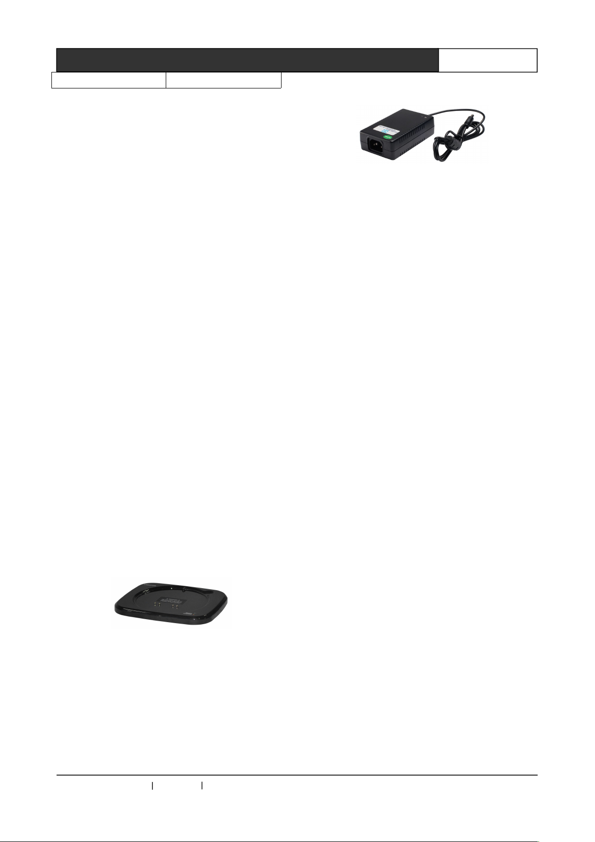
7.6 The Power Adapter
Function description
◆Used by speech unit for power supply and
power charge;
◆INPUT: 100V-240ac--1.5A;
◆OUTPUT: DC12V--3A.
CREATOR CHINA 2013-09 WWW.CREATOR1997.COM
Page 32
26
WiFi Conference System User‘s Manual
Chapter 8 Enclosure
8.1 CREATOR Conference System Protocol Code Formats and Their
Descriptions
Communication protocol:9600.N.8.1
Control code:The codes below are Hex format codes.
Format:A0 [XX] 10 00 07 [YY] FF FF FF AF [ZZ]
Description:
◆ The [XX], [YY] and [ZZ] are 16 hexadecimal formats, where [YY] represents the ID mapping code;
◆ Algorithm: [ZZ]=FFFF- ([XX]+10+00+07+[YY]+FF+FF+FF), choose the last 16 HEX as the result;
◆ Adopt "128 bit" algorithm, whenever speech unit ID (number) increases 128, the ID mapping code
should increase 7F, ID mapping code [YY] high bit should increase 1, and [XX] increases 1.If the
speech unit ID (number) continues to increase, [YY] is to start increasing at 0, the value of [ZZ] is to
comply with the above algorithm, as follows shown in the table:
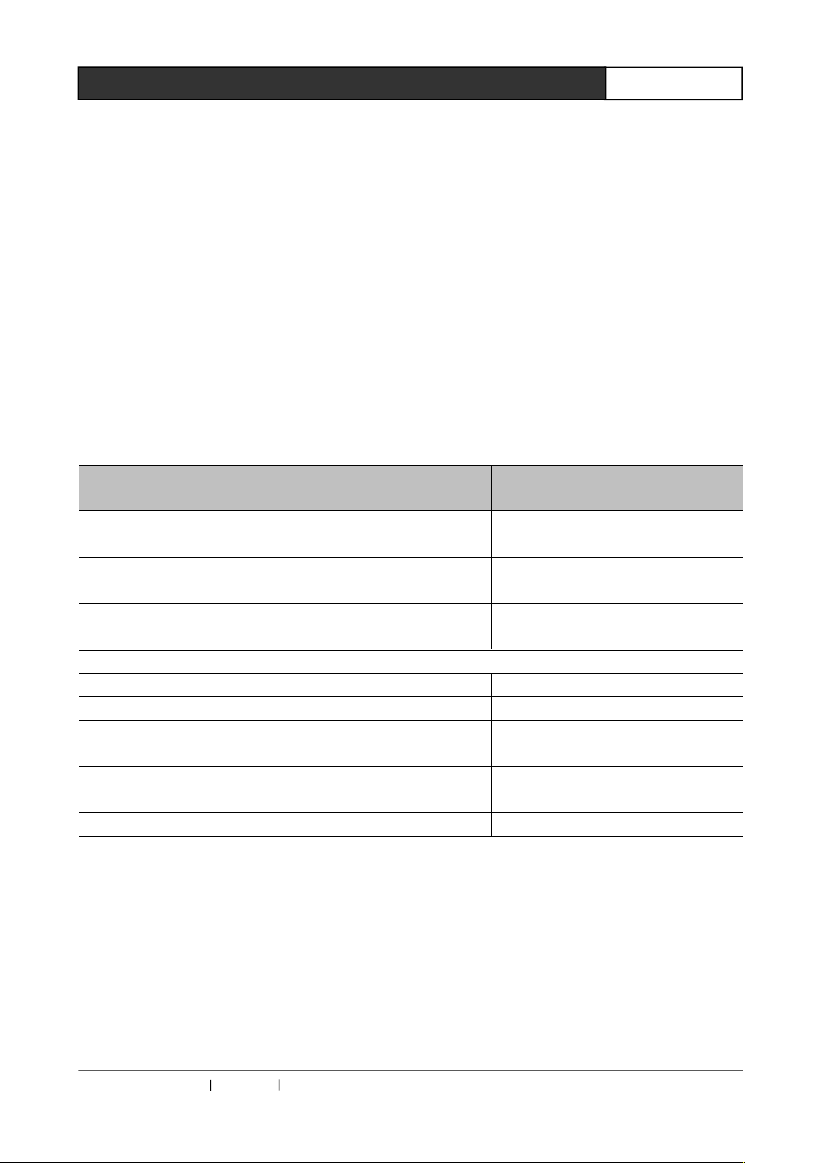
ID number of speech unit (10
hexadecimal format)
001 1 A0 10 10 00 07 01 FF FF FF AF DA
002 2 A0 10 10 00 07 02 FF FF FF AF D9
003 3 A0 10 10 00 07 03 FF FF FF AF D8
004 4 A0 10 10 00 07 04 FF FF FF AF D7
… … …
127 7F A0 10 10 00 07 7F FF FF FF AF 5C
ID mapping code of return
code (16 hexadecimal format)
Serial return code (16 hexadecimal
format)
128 100 A0 11 10 00 07 00 FF FF FF AF DA
129 101 A0 11 10 00 07 01 FF FF FF AF D9
130 102 A0 11 10 00 07 02 FF FF FF AF D8
131 103 A0 11 10 00 07 03 FF FF FF AF D7
132 104 A0 11 10 00 07 04 FF FF FF AF D6
… … …
255 17F A0 11 10 00 07 7F FF FF FF AF 5B
This table is the example list of the corresponding relationship between each coded speech unit
ID (number), serial code and the ID mapping code.
CREATOR CHINA 2013-09 WWW.CREATOR1997.COM
Page 33
27
WiFi Conference System User‘s Manual
8.2 PELCO-D Camera Control Protocol Code Formats and Their
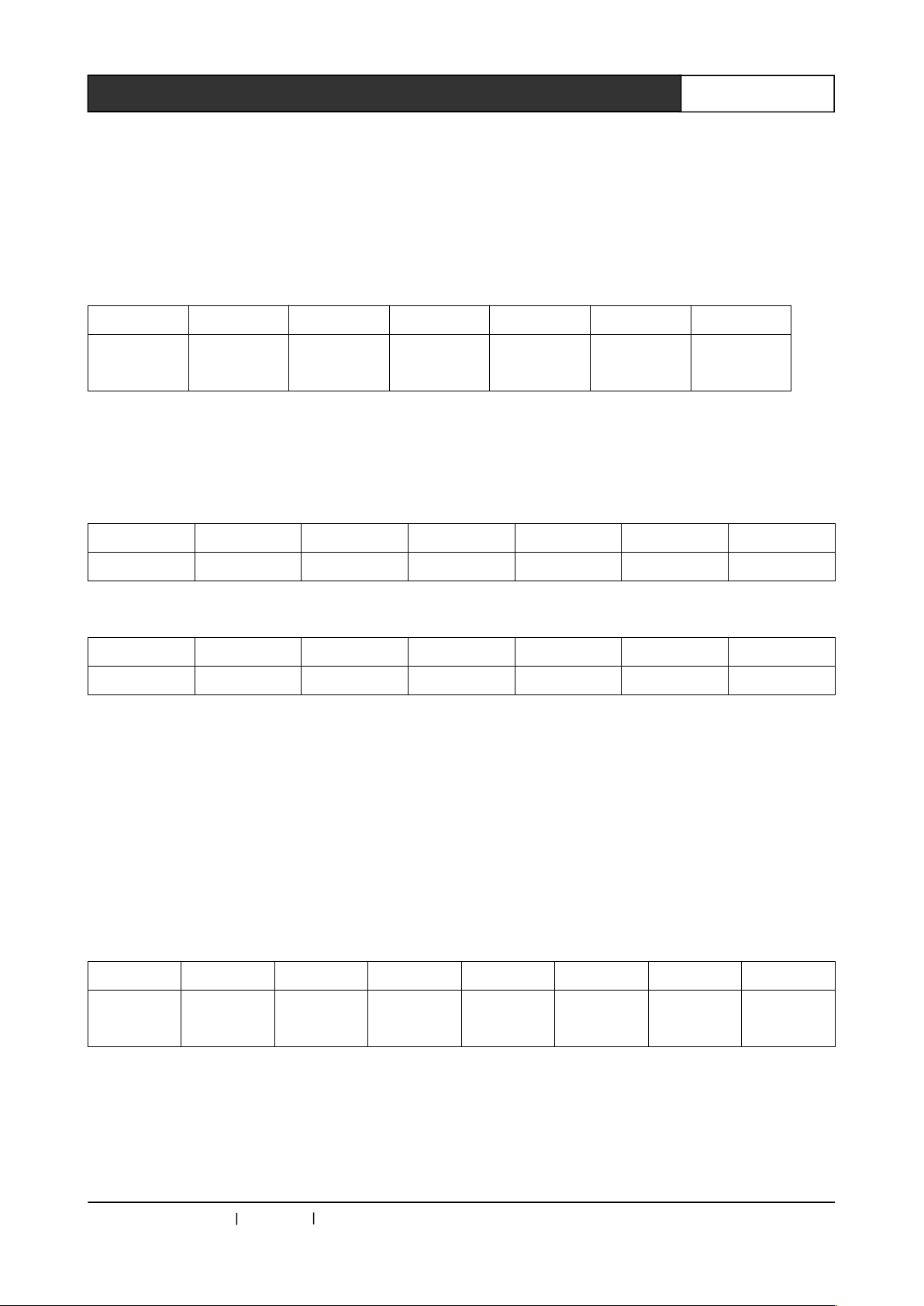
Byte 1 Byte2 Byte 3 Byte 4 Byte 5 Byte 6 Byte 7
FFH Address
code
Instruction
code1
Instruction
code 2
Data code1Data code
2
Check
code
◆Address code is the camera’s logical address, fixed as: 01H;
◆Algorithm: check code = MOD [(byte2 +byte 3 + byte 4 + byte5 + byte6) /100H];
Byte 1 Byte2 Byte 3 Byte 4 Byte 5 Byte 6 Byte 7
FFH 01H 00H 03H 00H Preset No. Check code
The camera preset recall command:
Byte 1 Byte2 Byte 3 Byte 4 Byte 5 Byte 6 Byte 7
FFH 01H 00H 07H 00H Preset No. Check code
Byte 1 Byte2 Byte 3 Byte 4 Byte 5 Byte 6 Byte 7 Byte 8
A0H
Address
code
Instruction
code 1
Instruction
code 2
Data code1Data code
2
AFH
Check
code
◆The address code is the camera’s logical address, fixed as: 01H;
◆Algorithm: check code = byte 1 XOR byte 2 XOR byte3 XOR byte 4 XOR byte 5 XOR byte 6 XOR byte
7. (XOR of bytes 1 to 7);
Descriptions
Communication protocol:9600.N.8.1
Control code:The codes below are Hex format codes.
PELCO-D command formats:
Description:
The camera preset setting command:
After the coding of the preset number and speech unit ID of the above table, each speech unit ID are
consistent. There are preset settings of 127 speech units, the 128th preset spot is for a panoramic
picture.
8.3 PELCO-P Camera Control Protocol Code Formats and Their
Descriptions
Communication protocol:9600.N.8.1
Control code:The codes below are Hex format codes.
PELCO-P command formats:
Description:
CREATOR CHINA 2013-09 WWW.CREATOR1997.COM
Page 34
28
WiFi Conference System User‘s Manual
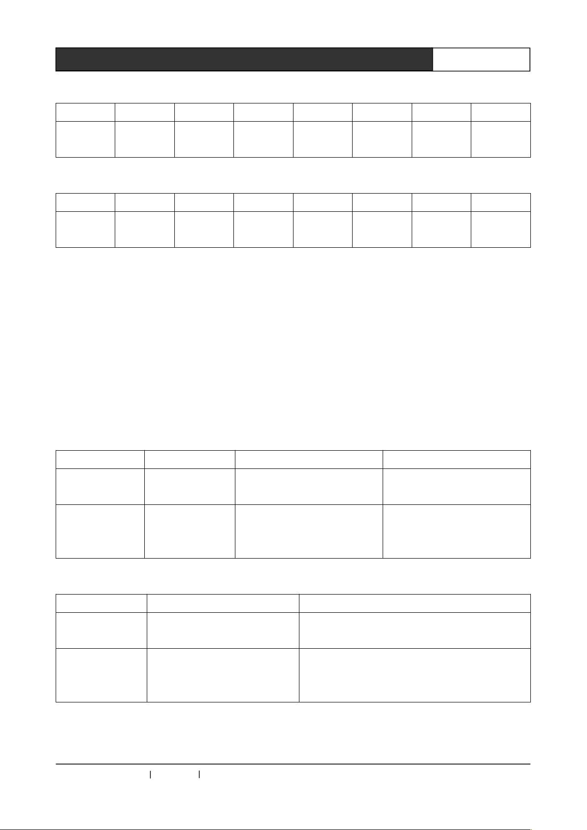
The camera preset setting command:
Byte 1 Byte2 Byte 3 Byte 4 Byte 5 Byte 6 Byte 7 Byte 8
A0H 01H 00H 03H 00H
Preset No.
AFH
Check
code
The camera preset recall command:
Byte 1 Byte2 Byte 3 Byte 4 Byte 5 Byte 6 Byte 7 Byte 8
A0H 01H 00H 07H 00H
Preset No.
AFH
Check
code
◆The address code is the camera’s logical address, fixed as: 01H;
Inquiry Packet Inq Packet Reply Description
CAM_ZoomPosInq8x 09 04 47 FF Y0 50 0Z 0Z 0Z 0Z FF ZZZZ:zoom data.
Pan-tiltPosInq 8x 09 06 12 FF
Y0 50 0W 0W 0W 0W 0Z 0Z
0Z 0Z FF
8x:81;
WWWW:pan;
ZZZZ:tilt.
The camera preset recall command:
Commad VISCA Packet Comments
CAM_Zoom 8x 01 04 47 0Z 0Z 0Z 0Z FF 8x:81;
ZZZZ:zoom data.
Pan-tiltDrive 8x 01 06 02 VV WW 0Y 0Y 0Y
0Y 0Z 0Z 0Z 0Z FF
8x:81;
YYYY:pan position data;
ZZZZ:tilt position data.
After the coding of the preset number and speech unit ID of the above table, each speech unit ID are
consistent. There are preset settings of 127 speech units. The 128th preset spot is for a panoramic
picture.
8.4 VISCA Camera Control Protocol Code Formats and Their
Descriptions
Communication protocol:9600.N.8.1
Control code:The codes below are Hex format codes.
Description:
The camera preset setting command:
When adopt VISCA camera protocol, the conference controller will preserve an absolute address for
each speech unit. You can directly recall the camera’s position. It supports the preset settings for 127
speech units and 1 panoramic picture.
CREATOR CHINA 2013-09 WWW.CREATOR1997.COM
Page 35

CREATOR CORPORATION(CHINA)
Copyright by CREATOR
Last Revision:09/2013
 Loading...