

Page 1

Professional
Professional
SDI/DVI/HDMI
SDI/DVI/HDMI
Switch
Switch
Scaler
Scaler
User
User
User
User
User
User
User
User
’
s
’
’
’
’
’
’
’
Manual
s
Manual
s
s
Manual
Manual
s
Manual
s
Manual
s
s
Manual
Manual
V1.1
CREATOR Corporation (China)
Page 2

Meaning of Symbols
■ Safety Instruction
Symbols are used in the Manual and devices, referring to the possible risk to users or others, as
well as the damage to property, for helping you to safely and properly use the devices. The instruction
and the implications are as follows. Please make sure your correct understanding of these instructions
before using the Manual.
To
remind user to conduct according to the attached operation
and maintenance commands. If ignore these information,
death or injury could possibly happen.
To
remind the user that the risky uninsulated voltage in the
device could caused electric shock to human.
CE authentication indicates the product is in line with the EU
safety regulation, and for assurance of safety use.
SGS Authentication indicates the product has reached the QC
standard of the global-biggest Swiss universe surveyor.
This product has acquired the ISO9001 International Quality
Authentication (Authentication authority: Germany Rheinland
TUV)
Caution:
nor put the useless parts in it. Please contact with qualified
service staff.
To
avoid electric shock, please don't open the case,
■ General information instruction
List the situation could cause unsuccessful operation or setup,
and relevant information needed to notice.
Page 3

Important Notices
Caution
To
ensure the device in reliable use and
personal safety, please abide by the following
items when in installation, use and maintenance:
Notice in installation
◆ Please DO NOT use the product in following
places: the places with dust, oily smoke,
electrical conductive dust, corrosive gas,
inflammable gas; the places with high
temperature, due, rain and wind exposures; the
places endangered by shock and vibration.
Electric shock, fire and incorrect operation could
also cause damage and deterioration to the
product.
◆ When conducting screw drilling and wiring
process, DO NOT let metal irons and wire lead
drop into the controller and air vent, which could
possibly cause fire, failure and accidental
operation.
◆ After finishing the installation, it is necessary
to ensure there is no foreign matter including the
packing material like contact paper on the
ventilation surface, otherwise, it could cause
poor heat dissipation while running, as well as
fire, failure and accidental operation.
◆ Avoid conducting wiring and plugging in/out
cable socket with electricity, otherwise, electric
shock, circuit damage could easily happen.
◆ Installation and wiring should be firm and
reliable. Poor contact could cause malfunction.
◆ With regard to the application situations with
strong interference, shielded cable should be
used for the input and output of HF signal, to
improve the anti-interference performance of the
system.
Note in Wiring
◆ Installation and wiring shouldn't be conducted
until external electric power is cut off, otherwise,
electric shock or device damage could happen.
◆ The product is grounded by the earth lead of
the power cable.
earth lead is necessary to be connected with the
ground. Before making connection with the
output end or input end of the product, please
ensure it is correctly grounding.
◆ Upon finish wiring, remove the sundries.
Please cover up the terminal plate for avoiding
electric shock.
Note for Operation and Maintenance
◆ Please DO NOT touch the terminal when with
electricity, otherwise, electric shock could
happen.
◆ Don't clean up and screw the terminal tight
before power is off. Such operation could cause
electric shock when with electricity.
◆ Please turn off the power before connecting or
disconnecting the communication signal cable,
peripheral modules or control units, otherwise,
device could be damaged and accidental
operation could happen.
◆ Please DO NOT disassemble the device, so
as to avoid internal electric components damage.
◆ It is necessary to read through the Manual and
fully ensure the safety, before altering the
program, trial running, starting and stopping
operation.
◆ Button battery shouldn't be replaced before
the power is off. If it has to be replaced when the
To
avoid electric shock, the
Page 4

device is running, it should be conducted by
professional electric technician wearing insulated
gloves.
Note for declaration of worthless.
When declaring of worthless, please note
◆ Explosion of electrolytic capacitor on the
circuit board could happen when burning it.
◆ Please classify and dispose it. Don't dispose it
into household garbage.
◆ Please deal it as industrial waste, or in
accordance with local environmental protection
regulation.
Page 5

Foreword
Professional SDI/DVI/HDMI Switch Scaler User’s Manual primarily introduces the exterior
structure and key functions and parameters of CR-SC-390, as well as its application in LED display
systems.
The Manual serves as an instruction for user's operation, rather than for maintenance service
purpose. Since the date of release, any function or relevant parameter alteration will be in supplement
command. Please refer to the manufacturer or dealers for inquiry.
CREATOR Electronics own the copyright of the Manual. Without permission, any unit or person
shall not take part or total of the Manual for business purpose.
The copyright of the Manual is protected by Copyright Law of People’s Republic of China and other
Intellectual Property Law. Without written permission, any copy or distribution is prohibited.
Page 6

Index
Chapter 1 Overview .............................................................................................................................................. 1
1.1 Functions and Features ........................................................................................................................ 1
1.2 Installation of Main Unit ........................................................................................................................ 2
Chapter 2 Main Unit Hardware ............................................................................................................................ 3
2.1 Panel functions ....................................................................................................................................... 3
2.2 Interface ................................................................................................................................................... 4
2.2.1 COM Port ................................................................................................................................. 4
2.2.2 RJ45 Internet Cable Production Method ............................................................................. 4
2.2.5 KEYBOARD Interface ............................................................................................................ 5
2.3 System Connection Diagram ............................................................................................................... 6
2.4 Operation with Panel Keys ................................................................................................................... 6
2.4.1 LCD Display ............................................................................................................................. 6
2.4.2 Key Light .................................................................................................................................. 6
2.4.3 Menu Setting ........................................................................................................................... 6
2.4.4 Example of Operations .......................................................................................................... 7
2.5 Menu Structure Diagram ....................................................................................................................... 8
Chapter 3 Control Keyboard Operations ........................................................................................................... 9
3.1 Control Keyboard Panel ........................................................................................................................ 9
3.2 Control Keyboard Operations ............................................................................................................ 10
Chapter 4 Command Set ....................................................................................................................................
4.1 Audio/video Switch Command ...........................................................................................................
4.1.1 Audio/video Switch Return Command ............................................................................... 12
4.2 Audio Tuning Command ..................................................................................................................... 12
4.2.1 Audio Tuning Return Command ......................................................................................... 12
4.3 Output Resolution Commands ........................................................................................................... 12
4.3.1 Output Resolution Return Commands .............................................................................. 13
4.4 Gamma Value Setting Command ...................................................................................................... 14
4.4.1 Gamma Value Setting Return Command ......................................................................... 14
4.5 Contrast Setting Command ................................................................................................................ 14
4.5.1 Contrast Setting Return Command .................................................................................... 15
11
11
4.6 Detail Enhancement Setting Command ........................................................................................... 15
4.6.1 Detail Enhancement Setting Return Command ............................................................... 15
4.7 Image Color Offset Setting command .............................................................................................. 15
4.7.1 Image Offset Setting Return Command ............................................................................ 16
Page 7

4.8 Network Setting Command ................................................................................................................ 16
4.9 Network Inquiry Command ................................................................................................................. 17
4.10 Network Interface Default Parameters ........................................................................................... 17
4.11 Equipment Status Reading Command ........................................................................................... 17
4.12 Factory Default Setting Restoring Command ................................................................................ 18
Chapter 5 Technical Parameters ....................................................................................................................... 19
Page 8

1Professional SDI/DVI/HDMI Switch Scaler User ’ s Manual
Chapter
Chapter
Chapter
Chapter 1
Professional SDI/DVI/HDMI switch scaler
SC-390 is a highly-integrated audio/video
converter and switcher for both video input of
YUV, YC, CV, VGA, DVI, HDMI and 3G-SDI
formats and video output of DVI, HDMI and SDI
formats. It is designed with CREATOR’s unique
audio/video switching technology to meet with
today’s need for use of display equipments of
high quality and high definition video, compatible
with multiple input/output resolutions, and offering
synchronous operation by panel keys and PC
software.
1.1
Functions
1.1
Functions
1.1
1.1 Functions
Functions and
◆ Compatible with YUV, YC, CV , VGA, DVI,
HDMI and 3G-SDI multiple signal source input,
supporting high definition display under DVI,
HDMI and 3G-SDI signal modes;
◆ Compatible with 4-way audio stereo input and
1-way audio stereo output, either balance or
non-balance;
◆ Audio input with video, namely, combined
conversion and switch of audio/video signal;
◆ Processing 1-way audio/video input or output
only at one time;
◆ Compatible with multiple input resolutions:
CV : 480i, 480P , 576i, 576P;
YC : 480i, 480P , 576i, 576P;
YUV : 480i, 480P , 576i, 576P, 720P , 1080i , 1080P;
VGA : 800X600@60Hz, 1024X768@60Hz,
1280X1024@60Hz , 1600X1200@60Hz;
and
Features
and
Features
and Features
Features
1
Overview
1
Overview
1 Overview
Overview
DVI : 800X600@60Hz, 1024X768@60Hz,
1152X864@75Hz, 1280X768@60Hz,
1280X960@60Hz, 1280X1024@60Hz,
1360X768@60Hz, 1366X768@60Hz,
1440X900@60Hz, 1600X1200@60Hz,
1920X1080@60Hz;
HDMI : 480i, 480P, 576i, 576P , 720P , 1080i , 1080P ,
800x600@60HZ ,
1024x768@60HZ, 1280x960@60HZ,
1280x1024@60HZ, 1440x900@60HZ,
1680x1050@60HZ, 1600x1200@60HZ;
SDI : 720X480P29.97, 720X480P59.94,
720X576P25, 720X576P50, 1280X720P60,
1280X720P59.94, 1280X720P50,
1280X720P30, 1280X720P29.97,
1280X720P25, 1280X720P24,
1280X720P23.97, 1920X1080P30,
1920X1080P29.97, 1920X1080P25,
1920X1080P24, 1920X1080P23.98,
1920X1080P60 , 1920X1080P59.94 ,
1920X1080P50, 1920X1035I60,
1920X1035I59.94, 1920X1080I50,
1920X1080I60, 1920X1080I59.94;
◆ Compatible with multiple output resolutions:
DVI/HDMI : 800X600@60Hz, 1024X768@60Hz,
1152X864@75Hz, 1280X720@60Hz,
1280X768@60Hz, 1280X960@60Hz,
1280X1024@60Hz, 1360X768@60Hz,
1366X768@60Hz, 1440X900@60Hz,
1600X1200@60Hz, 1920X1080@60Hz;
SDI : 1280X720P60, 1280X720P59.94,
1280X720P50, 1920X1080P30,
1920X1080P29.97, 1920X1080P25,
1920X1080P24, 1920X1080P23.98,
1920X1080P60, 1920X1080P59.94,
1920X1080P50, 1920X1080I50,
CREATOR CHINA 20
11
- 08 WWW.CREATOR199 7 .COM
Page 9
2Professional SDI/DVI/HDMI Switch Scaler User ’ s Manual
1920X1080I60, 1920X1080I59.94;
◆ Compatible with multiple ways of control, such
as CREATOR keyboard control, dual serial
interface control and Ethernet remote control, and
with operation information displayed on the front
panel LCD screen synchronously, for more direct,
convenient and flexible operation;
◆ Compatible with output on two separate
screens (DVI/HDMI, 3G-SDI), and enabling
parameter setting of the output format of either
way separately;
◆ Compatible with color enhancement, contrast
adjustment and isoparametric adjustment ,
satisying your needs for different image and
screen visual effects;
1.2
Installation
1.2
Installation
1.2
1.2 Installation
Installation of
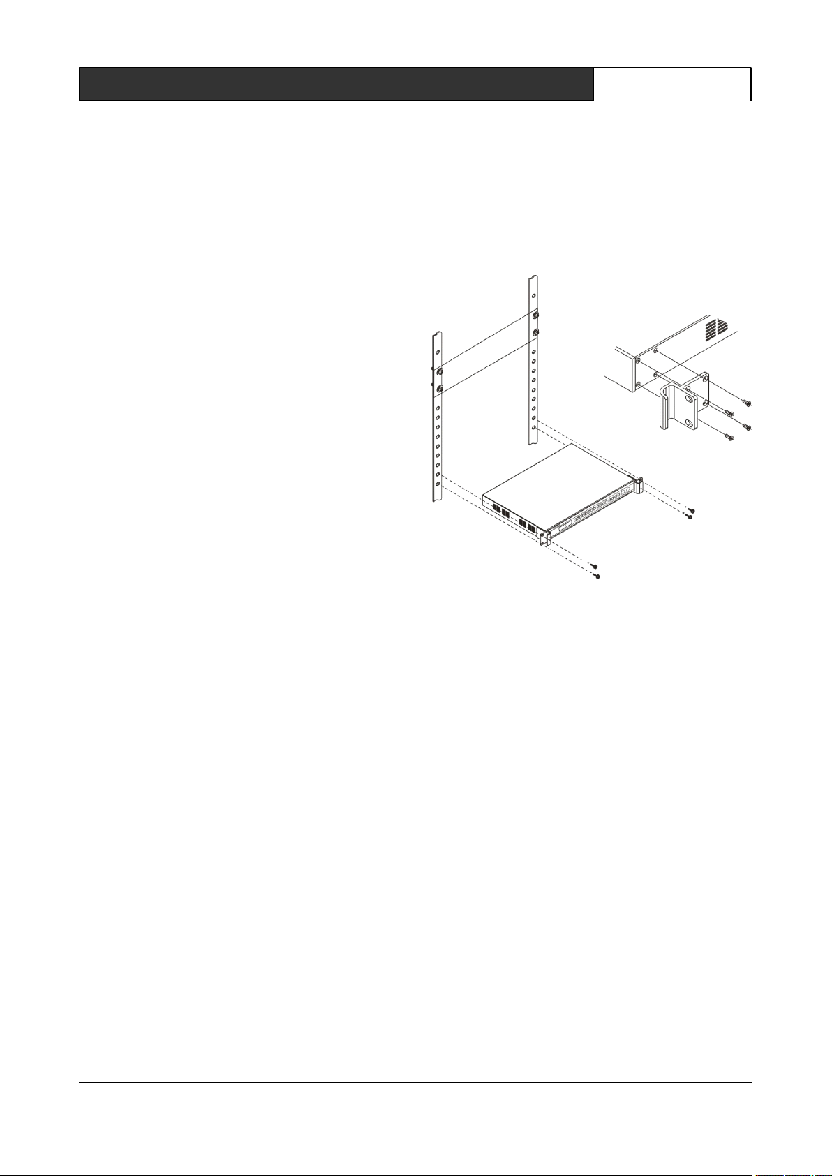
CR-SC-390’s main unit may be installed on a
standard 19 ” housing. The accessories of each
main unit include a pair of brackets and a bag of
screws for mounting on the housing, in the way as
shown below.
of
Main
of
Main
of Main
Main Unit
Unit
Unit
Unit
◆ Featuring operation memory function, with
which function the system automatically saves
the current status when there is no other
operation in 10 seconds after setting is done;
◆ Featuring temperature self-detecting function,
with which function the system reads the
temperature every 3 seconds and displays on the
LCD screen, to ensure safety in use;
◆ Featuring automatic fan on function, with which
function the fan will be automatically on when the
equipment temperature reaches 30oC for cooling
the equipment, and the fan will be automatically
off when the equipment temperature drops to
28oC;
◆ Featuring factory default value restoring
function;
◆ Adopting 1U standard 19 ” housing design to fit
with a standard 19 ” housing.
CREATOR CHINA 20
11
- 08 WWW.CREATOR199 7 .COM
Page 10
3Professional SDI/DVI/HDMI Switch Scaler User ’ s Manual
Chapter
Chapter
Chapter
Chapter 2
2.1
Panel
2.1
Panel
2.1
2.1 Panel
Panel functions
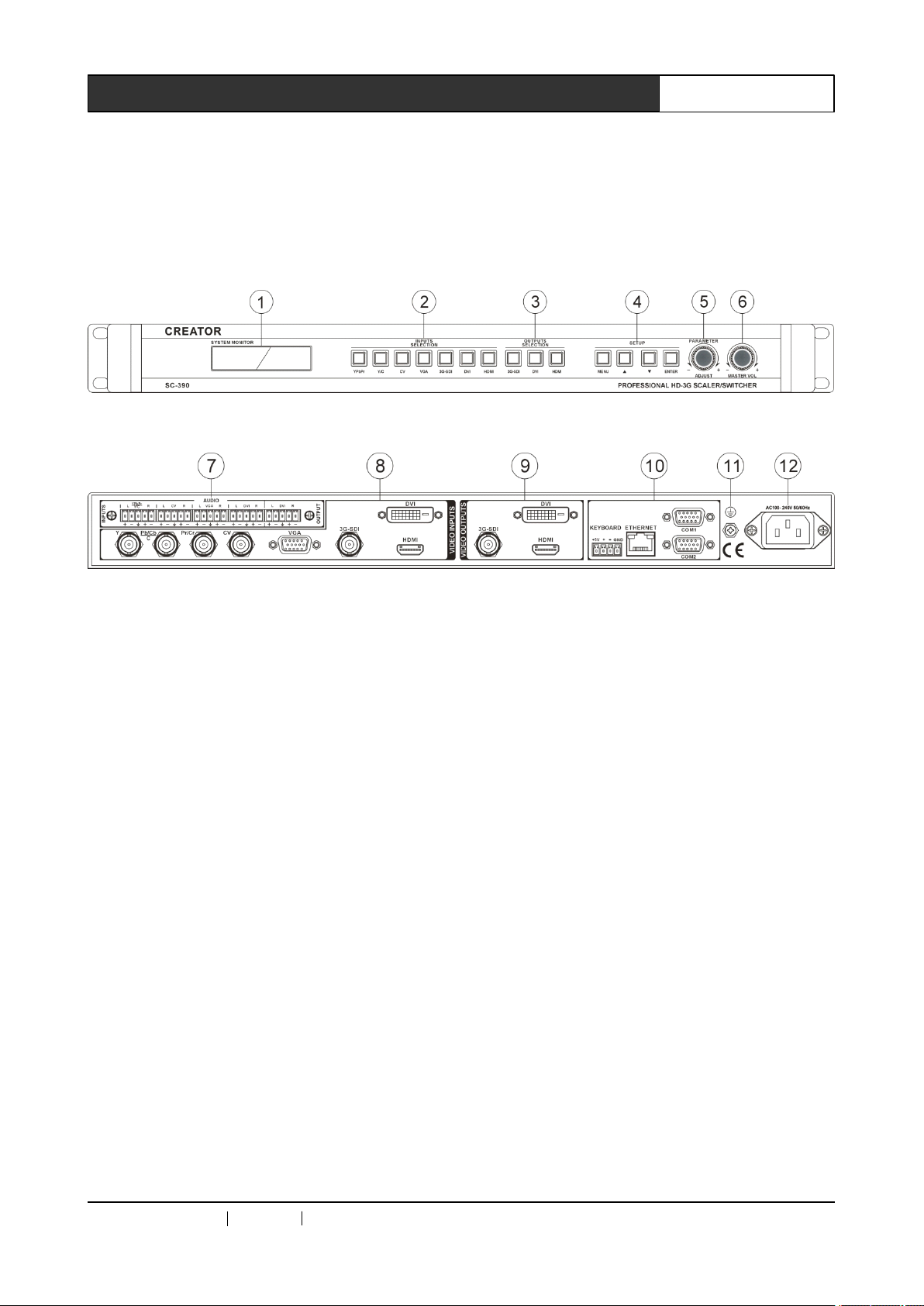
Front panel:
Rear panel:
1)
LCD
1)
LCD
1)
1) LCD
LCD DISPLAY
For display of the current status of the output
screen and operation information.
2)
INPUTS
2)
INPUTS
2)
2) INPUTS
INPUTS SELECTION
Input signal selection, including YPbPr, Y/C,
CV, VGA, 3G-SDI, DVI and HDMI total 7-way
signals for selection.
3)
OUTPUTS
3)
OUTPUTS
3)
3) OUTPUTS
OUTPUTS SELECTION
Output signal selection, including 3G-SDI,
DVI and HDMI total 3-way signals for selection,
corresponding to the output ports on the rear
panel.
4)
MENU
4)
MENU
4)
4) MENU
MENU
Menu setting selection key is configured on
the front panel. Press this key to enter menu
setting, and the menu key on the front panel will
be shown on the LCD display, and at the same
time the key lights will be on.
▲ ▼
Direction key. Use this key to move up/down
functions
functions
functions
DISPLAY
DISPLAY
DISPLAY
SELECTION
SELECTION
SELECTION
SELECTION
SELECTION
SELECTION
2
Main
2
Main
2 Main
Main Unit
Unit
Unit
Unit Hardware
to select the required parameters for the item to
be set.
next level from the menu on the front panel keys.
5)
5)
5)
5) PARAMETER/ADJUST
knob is used as the direction key for selecting
parameters for the required items between left
and right.
6)
6)
6)
6) MASTER
audio volume (not adjustable under HDMI and
3G-SDI signal input).
7)
7)
7)
7) AUDIO
audio signal input (YPbPr/Y/C, CV, VGA, DVI)
and 1-way DVI audio signal output.
8)
VIDEO
8)
VIDEO
8)
8) VIDEO
VIDEO INPUTS
Hardware
Hardware
Hardware
ENTER
ENTER
ENTER
ENTER
Press Enter and move to the menu in the
PARAMETER/ADJUST
PARAMETER/ADJUST
PARAMETER/ADJUST
In the menu setting with front panel keys, this
MASTER
MASTER
MASTER VOL
Volume adjust knob, for adjusting the input
AUDIO
AUDIO
AUDIO INPUTS/
Audio input and output port, offering 4-way
VOL
VOL
VOL
INPUTS/
INPUTS/
INPUTS/ AUDIO
INPUTS
INPUTS
INPUTS
AUDIO
AUDIO
AUDIO OUTPUTS
OUTPUTS
OUTPUTS
OUTPUTS
CREATOR CHINA 20
11
- 08 WWW.CREATOR199 7 .COM
Page 11
Video input port, available to 7-way video
input (YPbPr, Y/C, CV, VGA, 3G-SDI, DVI and
HDMI), for connection with peripheral video signal
source equipment such as DVD, PC,
high-definition player, etc.
9)
VIDEO
9)
VIDEO
9)
9) VIDEO
VIDEO OUTPUTS
Video output port, offering 3-way video
output (3G-SDI, DVI, HDMI), for connection with
3G-SDI, DVI, HDMI interface video displayers,
such as high-definition display and player, or for
connection with such equipment as video player.
OUTPUTS
OUTPUTS
OUTPUTS
4Professional SDI/DVI/HDMI Switch Scaler User ’ s Manual
Difference between ▲ ▼ direction key and
PARAMETER/ADJUST knob:
▲ ▼ direction key can only be used when
inquiring about and selecting parameters of
resolution and current status;
PARAMETER/ADJUST knob can not only be
used when performing the above functions, but
also be used when selecting and setting such
parameters as gamma, contrast, detail strong and
image color.
2.2
Interface
2.2
Interface
2.2
2.2 Interface
Interface
The input/output of audio of 3G-SDI and
HDMI signal formats is transmitted and switched
together with its video signal input/output.
10)
10)
10)
10) KEYBOARD
interface
interface
interface
interface
for use together with CREATOR CR-MCP100
control keyboard.
ETHERNET--RJ45
ETHERNET--RJ45
ETHERNET--RJ45
ETHERNET--RJ45 network
connection with LAN and Ethernet. Green light
when on indicates connection is proper, while
flashing orange light indicates data are being
received or sent.
RS-232
RS-232
RS-232
RS-232
for connection with PC or a third party control
equipment (such as CREATOR, CRESTRON,
AMX control main unit, etc.).
11)
11)
11)
11) Grounding
KEYBOARD
KEYBOARD
KEYBOARD —
Offering 1-way extension keyboard interface,
Providing 1-way Ethernet connection port, for
Serial interface, offering 2-way RS-232 port,
Grounding
Grounding
Grounding post.
—
Extension
—
Extension
— Extension
Extension keyboard
network
network
network interface
post.
post.
post.
interface
interface
interface
keyboard
keyboard
keyboard
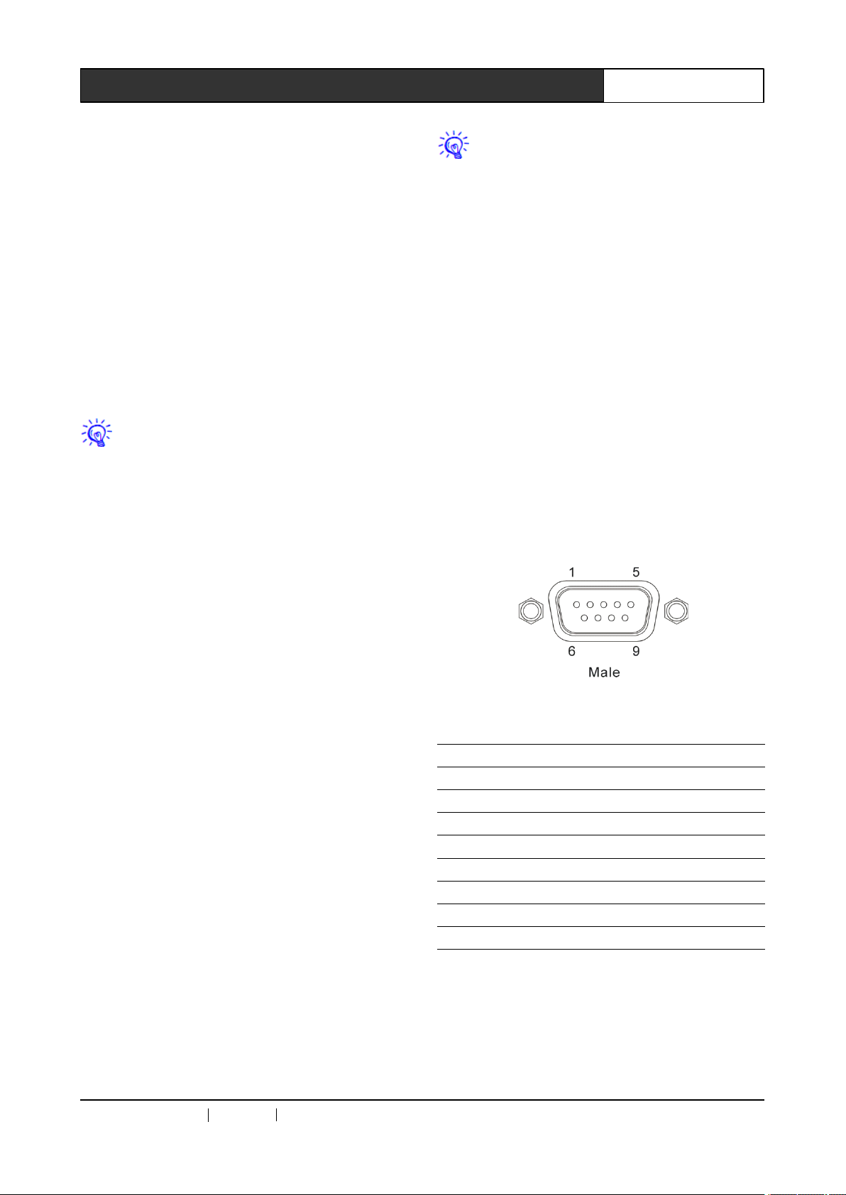
2.2.1
COM
2.2.1
COM
2.2.1
2.2.1 COM
COM Port
Professional SDI/DVI/HDMI switch scaler
may be used to control various types of control
systems. LED screen controller may be controlled
through RS-232 serial interface or the optional
Ethernet control port.
COM port pins are described as follows:
Pin Signal Description
1 - Empty
2 TXD Transmitting data
3 RXD Receiving data
4 - Empty
5 GND Signal Ground
6 - Empty
7 - Empty
8 - Empty
9 - Empty
Port
Port
Port
12)
System
12)
System
12)
12) System
System power
System power input is AC 100V-240V
50/60Hz.
CREATOR CHINA 20
power
power
power input
input
input
input port
11
port
port
port
- 08 WWW.CREATOR199 7 .COM
2.2.2
2.2.2
2.2.2
2.2.2 RJ45
Method
Method
Method
Method
wiring material in this system, and is connected
with internet equipment through RJ45 connector
RJ45
RJ45
RJ45 Internet
CAT-5 (Category-5 Cable) is used as the
Internet
Internet
Internet Cable
Cable
Cable
Cable Production
Production
Production
Production
Page 12
5Professional SDI/DVI/HDMI Switch Scaler User ’ s Manual
(commonly known as the crystal head) on both
ends. The standard way for connection of the
twisted pair is not a casual rule, but provided for
the purpose of ensuring symmetric layout of wire
and cable connectors, so as to offset the possible
interruption between wires and cables between
connectors. Generally, CAT-5e cables have four
pairs of stranded wires inside, which are marked
by different colors.
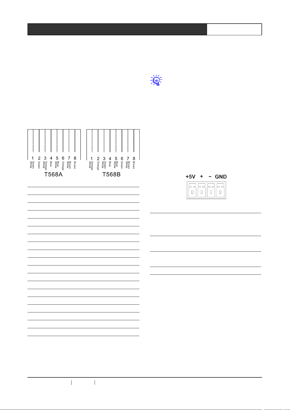
There are two ways of connection: EIA/TIA
568B standard and EIA/TIA 568A standard.
Crossover wiring: with one end connected
subject to the T568A wiring sequence, and with
the other connected subject to the T568B wiring
sequence.
In connection with a network router,
straight through wiring method will be used; in
connection with a PC computer, crossover wiring
method will be used.
2.2.5
KEYBOARD
2.2.5
KEYBOARD
2.2.5
2.2.5 KEYBOARD
KEYBOARD Interface
1-way KEYBOARD interface is provided,
through which connection with CR-MCP100
extension keyboard is enabled to conduct
channel switch operation on the switch scaler.
KEYBOARD has a 4-digit 3.8mm phoenix
interface, and its pins are described as follows:
Interface
Interface
Interface
T568A Wiring Sequence
1 White Green
2 Green
3 White Orange
4 Blue
5 White Blue
6 Orange
7 White Brown
8 Brown
T568B Wiring Sequence
1 White Orange
2 Orange
3 White Green
4 Blue
5 White Blue
6 Green
7 White Brown
8 Brown
Pin Signal Description
Output DC5V/0.5A
1 +5V
2 +
3 -
4 GND Signal Ground
Able to provide power to the
operation of MCP100
For use of RS-485 protocol,
DAT A+
For use of RS-485 protocol,
DAT A-
Straight through wiring: both ends are
connected subject to the standard T568B wiring
sequence.
CREATOR CHINA 20
11
- 08 WWW.CREATOR199 7 .COM
Page 13
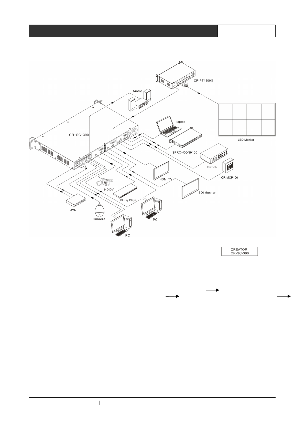
2.3
System
2.3
System
2.3
2.3 System
System Connection
Connection
Connection
Connection Diagram
Diagram
Diagram
Diagram
6Professional SDI/DVI/HDMI Switch Scaler User ’ s Manual
2.4
Operation
2.4
Operation
2.4
2.4 Operation
Operation with
2.4.1
2.4.1
2.4.1
2.4.1 LCD
the LCD background light will be off. Press any
key to turn it on.
2.4.2
2.4.2
2.4.2
2.4.2 Key
indication lights flashing in red color. When a key
is pressed down, the indication light in the key will
be flashing.
2.4.3
2.4.3
2.4.3
2.4.3 Menu
background light of the LCD display will be on at
the same time, and the system status “ Loading …”
will be shown on the display. After the system is
LCD
Display
LCD
Display
LCD Display
Display
When there is no operation in 10 seconds,
Key
Light
Key
Light
Key Light
Light
The keys on the front panel have operating
Menu
Menu
Menu Setting
After power connection is properly done, the
Setting
Setting
Setting
with
with
with Panel
Panel
Panel
Panel Keys
Keys
Keys
Keys
started, the main screen will be
displayed.
Menu
Menu
Menu
Menu operation
follows:
follows:
follows:
follows:
Enter menu setting Select the item to be
set Select parameter for the item to be set
Confirm setting
in 10 seconds, the system will automatically save
the set parameters.
Operating
Operating
Operating
Operating steps
Step
Step
Step
Step 1,
and press “ MENU ” to enter menu setting;
Step
Step
Step
Step 2,
knob to move up/down or left/right to select the
operation
operation
operation steps
After setting is done, if there is no operation
steps
steps
steps in
1,
1,
1, press any key to turn on the LCD display,
2,
2,
2, press “▲ and ▼” key or PARAMETER
steps
steps
steps may
in
in
in details:
may
may
may be
details:
details:
details:
be
summarized
be
summarized
be summarized
summarized as
as
as
as
CREATOR CHINA 20
11
- 08 WWW.CREATOR199 7 .COM
Page 14
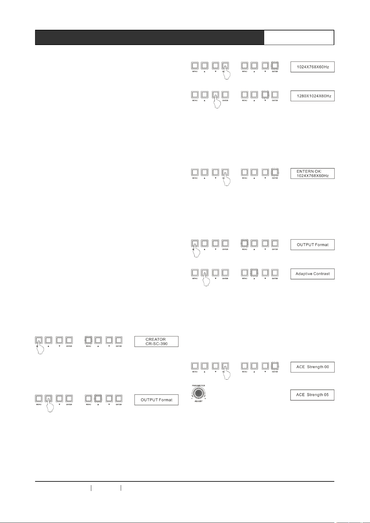
item to be set, and then press “ ENTER ” key to
confirm enter;
Step
3,
Step
3,
Step
Step 3,
3, press “▲ and ▼” key or PARAMETER
knob to move up/down or left/right to select the
parameter for the item to be set, and
corresponding parameter information will be
shown by turns on the LCD display upon every
pressing;
After entering the parameter setting menu,
the current status of the item to be set in the
system will be shown as the first parameter
information;
Step
4,
Step
4,
Step
Step 4,
press “ ENTER ” key to confirm selection;
Step
Step
Step
Step 5,
parameters, then after confirming each parameter,
press “ MENU ” key to return to the menu of the
upper level, and simply repeat the operations in
Step 2, 3 and 4.
4, after selecting the needed parameter,
5,
5,
5, if it is necessary to set multiple
7Professional SDI/DVI/HDMI Switch Scaler User ’ s Manual
4 、 Press “ ENTER ” to confirm change, and the
parameter information is shown on the LCD
screen after successful setting;
5 、 Press “ MENU ” key to return to the upper menu,
and use the “▲▼” key to search for the item
“ Adaptive Contrast ” to be set;
2.4.4
2.4.4
2.4.4
2.4.4 Example
1280X1024@60Hz, and set contrast to 5.0.
1 、 Press “ MENU ” key to enter menu setting, and
on the LCD display it is shown as follows;
2 、 Press “ MENU ” key to enter menu setting, and
use the “▲▼” key to select the parameter for the
“ OUTPUT Format ” ;
3 、 Press “ ENTER ” to confirm setting, and enter
parameters setting. At this moment, on the LCD
display shows the current status of the item to be
set. Use the “▲▼” key to search for the
parameter 1280X1024@60Hz;
Example
Example
Example of
E.g.: Set the output resolution as
of
Operations
of
Operations
of Operations
Operations
6 、 Press “ ENTER ” to confirm setting, and enter
parameters setting. At the moment, the LCD
display should show the current status of the item
to be set. Use “ PARAMETER ” knob to roll
left/right to set to the required parameter “ 5.0 ” and
finish setting.
CREATOR CHINA 20
11
- 08 WWW.CREATOR199 7 .COM
Page 15
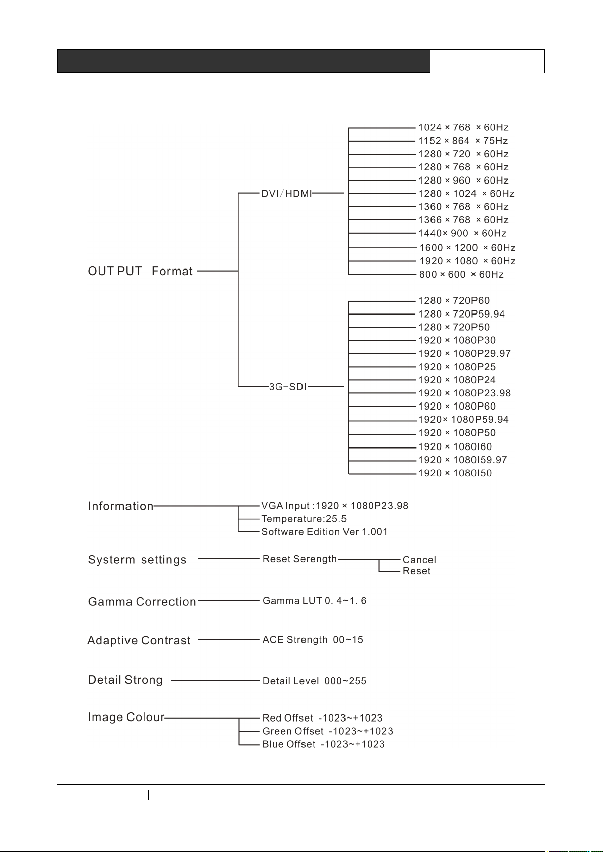
2.5
Menu
2.5
Menu
2.5
2.5 Menu
Menu Structure
Structure
Structure
Structure Diagram
Diagram
Diagram
Diagram
8Professional SDI/DVI/HDMI Switch Scaler User ’ s Manual
CREATOR CHINA 20
11
- 08 WWW.CREATOR199 7 .COM
Page 16
9Professional SDI/DVI/HDMI Switch Scaler User ’ s Manual
Chapter
Chapter
Chapter
Chapter 3
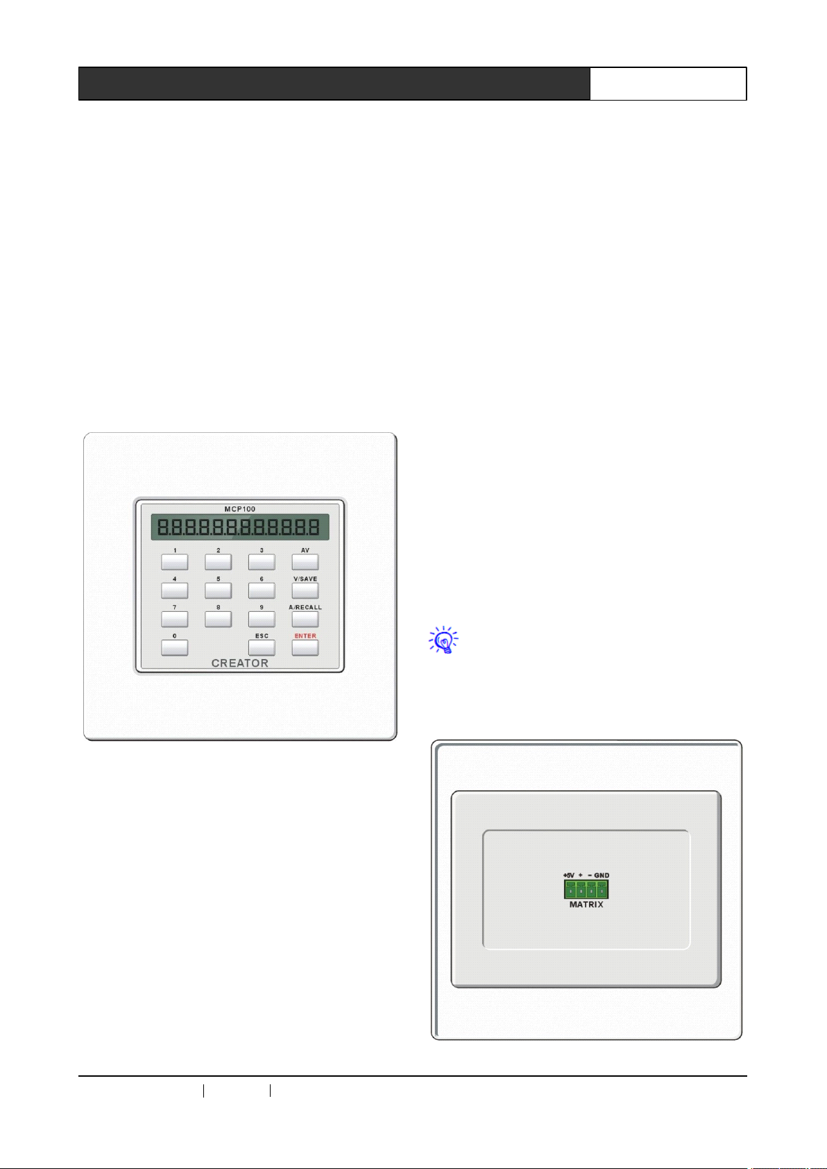
CREATOR ’ s CR-MCP100 matrix control
keyboard may be used together with its
professional SDI/DVI/HDMI switch scaler through
KEYBOARD interface under RS-485
communication protocol, for conducting remote
audio/video switch control operation with the
switch scaler.
3.1
Control
3.1
Control
3.1
3.1 Control
Control Keyboard
Front panel:
Keyboard
Keyboard
Keyboard Panel
3
Control
3
Control
3 Control
Control Keyboard
Panel
Panel
Panel
Keyboard
Keyboard
Keyboard Operations
key 6 stands for DVI input
key 7 stands for HDMI input
Output channel selection key:
key 1 stands for 3G-SDI output
key 2 stands for DVI output
key 3 stands for HDMI output
AV--Audio/video
AV--Audio/video
AV--Audio/video
AV--Audio/video synchronous
selection
selection
selection
selection key
signal in the same channel onto the same output
channel.
E.g.: Press “ 1 ” , “ AV ” , “ 2 ” , “ ENTER ” in turn, to
synchronously switch the YpbPr input signal in
the channel 1 to the DVI output channel 2.
key
key
key
For synchronously switching the audio/video
Operations
Operations
Operations
synchronous
synchronous
synchronous switch
switch
switch
switch
0,
1
…
7
—
0,
1
0,
0, 1
1 …
and input channel, corresponding to the 7-way
input channel selection keys and the 3-way output
channel selection keys on the front panel of the
professional SDI/DVI/HDMI switch scaler , as
follows:
Input channel selection key:
key 1 stands for YpbPr input
key 2 stands for YC input
key 3 stands for CV input
key 4 stands for VGA input
key 5 stands for 3G-SDI input
Output/input
…
7
—
Output/input
… 7
7 —
— Output/input
Output/input channel
Used for setting audio/video signal output
channel
channel
channel selection
selection
selection
selection key
key
key
key
ENTER
ENTER
ENTER
ENTER —
action.
the professional SDI/DVI/HDMI switch scaler.
Rear panel:
—
Order
—
Order
— Order
Order execution
Confirm switch selection, and perform switch
Other keys are inoperable for operation of
execution
execution
execution key
key
key
key
CREATOR CHINA 20
11
- 08 WWW.CREATOR199 7 .COM
Page 17
—
MATRIX —
interface, used for connection with the
KEYBOARD interface of the professional
SDI/DVI/HDMI switch scaler , from which power is
supplied to the CR-MCP100 matrix control
keyboard. For its pin description, please refer to
Section 2.2.5: KEYBOARD Interface Description,
of this Manual.
—
— is the RS-485 communication
10Professional SDI/DVI/HDMI Switch Scaler User ’ s Manual
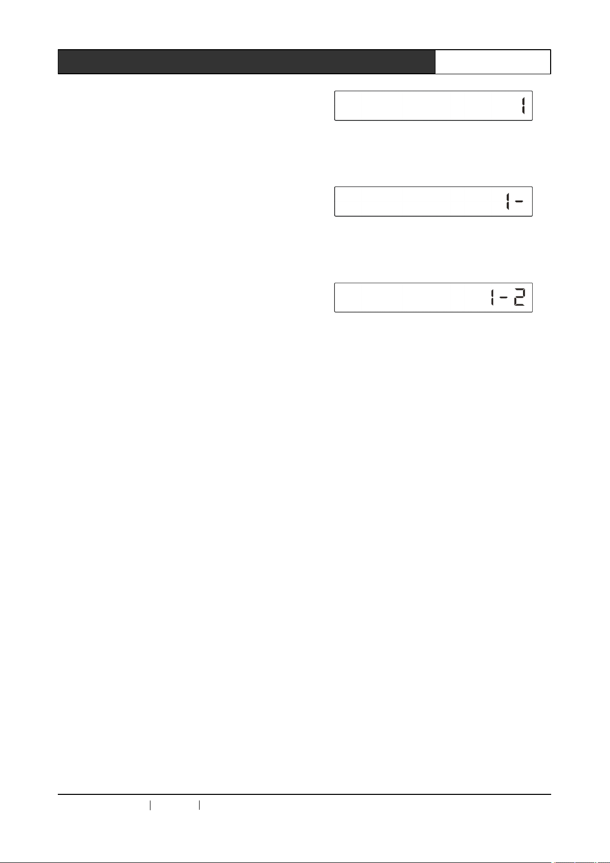
2 、 Press the
audio/video synchronous switch mode, and the
LCD display shows the following:
AV
key quickly and select the
3.2
Control
3.2
Control
3.2
3.2 Control
Control Keyboard
In operation, the operating status will be
shown in real time on the LCD screen of the
control keyboard panel and the front panel key of
the professional SDI/DVI/HDMI switch scaler.
Input/output
Input/output
Input/output
Input/output switch
follows:
follows:
follows:
follows:
“ input channel ” + “ AV ” + “ output channel ” + “ ENTER ”
Input/output
Input/output
Input/output
Input/output switch
follows:
follows:
follows:
follows:
Step
1,
Step
1,
Step
Step 1,
1, press numeric key to select input channel.
A
maximum of 7 input channels may be selected,
and other numeric keys inoperable;
Step
2,
Step
2,
Step
Step 2,
2, select the switch mode AV;
Step
3,
Step
3,
Step
Step 3,
3, press the numeric key to select the output
channel.Amaximum of 3 output channels may be
selected, and other numeric keys are inoperable;
Keyboard
Keyboard
Keyboard Operations
switch
switch
switch operation
switch
switch
switch operation
operation
operation
operation method
operation
operation
operation steps
Operations
Operations
Operations
method
method
method is
steps
steps
steps are
is
is
is as
are
are
are as
3 、 Select the output channel, quickly press
numeric key 1, and the LCD display shows the
following:
as
as
as
as
as
as
4 、 Lastly, quickly press ENTER key to perform the
switch operation.A“ beep ” will be heard, and the
switch operation is done.
Step
Step
Step
Step 4,
operation and perform switch action. The buzzer
will produce a short “ beep ” .
Example:
Example:
Example:
Example:
synchronously
synchronously
synchronously
synchronously switched
channel
channel
channel
channel 2,
1 、 Select the input channel. Press numeric key 1
quickly, and at this moment the LCD display
shows the following:
CREATOR CHINA 20
4,
4,
4, press ENTER key to confirm switch
If
the
If
the
If
If the
the YpbPr
2,
YpbPr
YpbPr
YpbPr signal
the
2,
the
2, the
the operation
signal
signal
signal in
switched
switched
switched to
operation
operation
operation is
11
in
channel
in
channel
in channel
channel 1
to
the
to
to the
is
as
is
as
is as
as follows:
- 08 WWW.CREATOR199 7 .COM
DVI
the
DVI
the DVI
DVI output
follows:
follows:
follows:
1
1
1 is
output
output
output
is
is
is
Page 18
Professional SDI/DVI/HDMI Switch Scaler User ’ s Manual
11
Chapter
Chapter
Chapter
Chapter 4
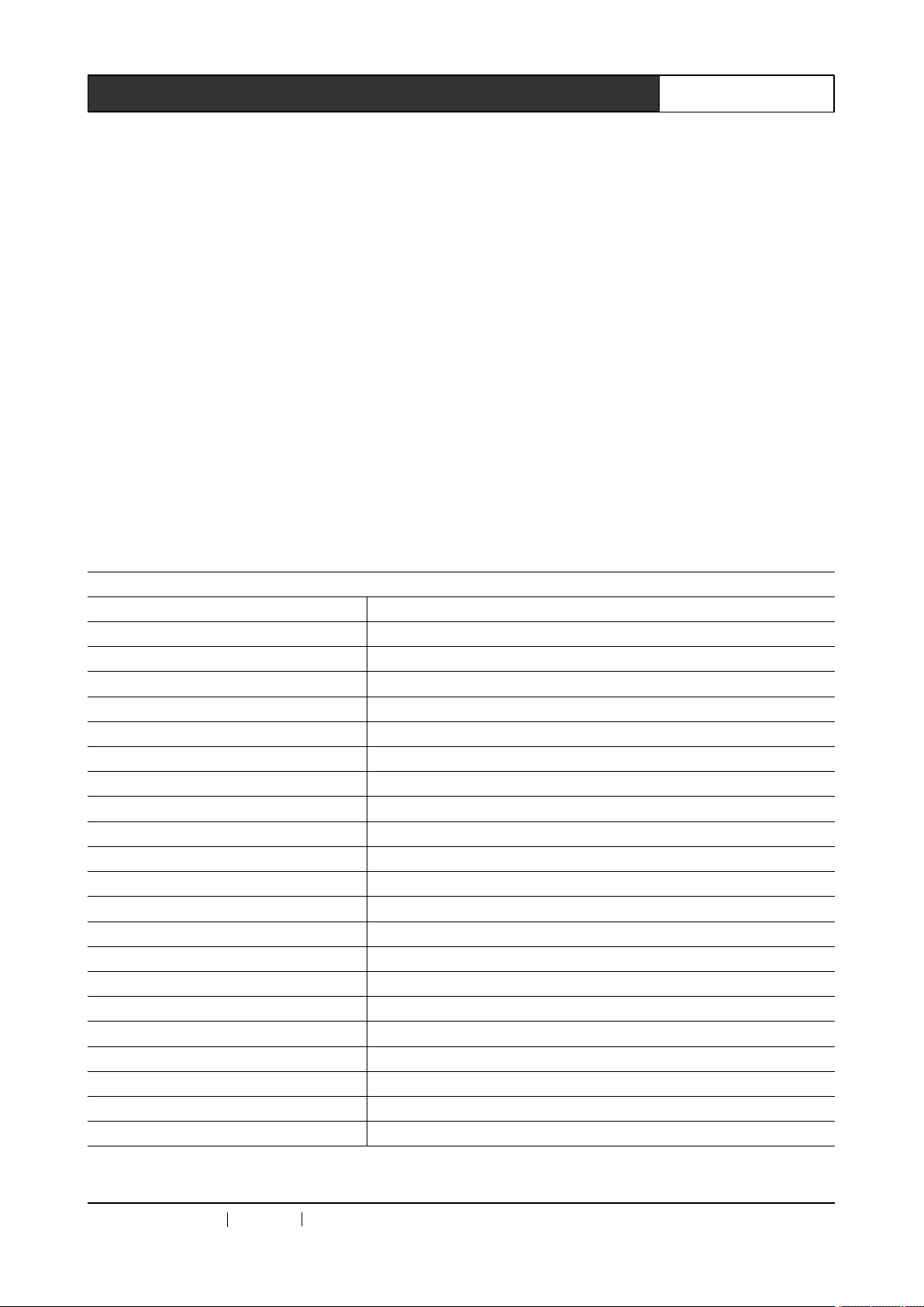
Serial interface baud rate: 9600 Data bit: 8 Stop bit: 1 Parity check: No
Network: This machine operates in the TCP server mode
Input num 1 stands for YpbPr
Input num 2 stands for YC
Input num 3 stands for CV
Input num 4 stands for VGA
Input num 5 stands for 3G-SDI
Input num 6 stands for DVI
Input num 7 stands for HDMI
Output num 1 stands for 3G-SDI
Output num 2 stands for DVI
Output num 3 stands for HDMI
4.1
Audio/video
4.1
Audio/video
4.1
4.1 Audio/video
Audio/video Switch
format: *X->Y! X: Input num
Command Function Description
*1->1! YpbPr input 3G-SDI output
*1->2! YpbPr input DVI output
*1->3! YpbPr input HDMI output
*2->1! Y/C input 3G-SDI output
*2->2! Y/C input DVI output
*2->3! Y/C input HDMI output
*3->1! CV input 3G-SDI output
*3->2! CV input DVI output
*3->3! CV input HDMI output
*4->1! VGA input 3G-SDI output
*4->2! VGA input DVI output
*4->3! VGA input HDMI output
*5->1! 3G-SDI input 3G-SDI output
*5->2! 3G-SDI input DVI output
*5->3! 3G-SDI input HDMI output
*6->1! DVI input 3G-SDI output
*6->2! DVI input DVI output
*6->3! DVI input HDMI output
*7->1! HDMI input 3G-SDI output
*7->2! HDMI input DVI output
*7->3! HDMI input HDMI output
Switch
Switch
Switch Command
Command
Command
Command
Y:
Output num
4
Command
4
Command
4 Command
Command Set
Set
Set
Set
CREATOR CHINA 20
11
- 08 WWW.CREATOR199 7 .COM
Page 19
12Professional SDI/DVI/HDMI Switch Scaler User ’ s Manual
4.1.1
4.1.1
4.1.1
4.1.1 Audio/video
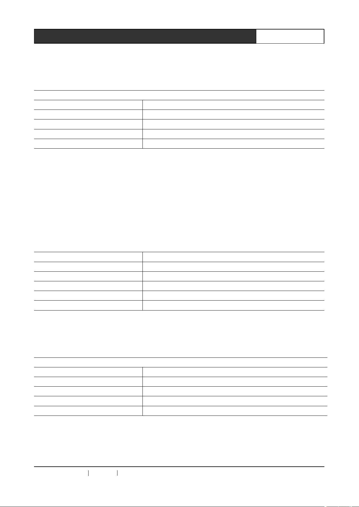
audio/video switch, except that “ key operate: ” is added before the command, and both share the same
function description. E.g.:
4.2
4.2
4.2
4.2 Audio
Audio
Audio
Audio
Audio tuning
Volume range -60.00dB ~ +8.00dB
Tuning step is 00.5dB
format: #X->YdB! X: Input num
YpbPr and YC share the same audio way. Set #1->+00.0dB! and get the same result as the #2->+00.0dB!
command, both meaning YpbPr YC input volume set as +00.0dB.
3G-SDI and HDMI input audio volume is not adjustable.
Example:
Audio/video
Audio/video
Audio/video Switch
The audio/video switch return command in the panel key operation is similar with the command for
format: key operate: *X->Y! X: Input num
Command Function Description
key operate: *1->1! YpbPr input 3G-SDI output
key operate: *1->2! YpbPr input DVI output
key operate: *1->3! YpbPr input HDMI output
key operate:...... ......
Audio
Audio
Audio Tuning
tuning
tuning
tuning commands
Command Function description
#1->+00.0dB! YpbPr YC input volume set as +00.0dB
#2->-01.0dB! YpbPr YC input volume set as -01.0dB
#3->+05.0dB! CV input volume set as +05.0dB
#4->-20.0dB! VGA input volume set as -20.0dB
#6->+08.0dB! DVI input volume set as +08.0dB
Tuning
Tuning
Tuning Command
commands
commands
commands
Switch
Switch
Switch Return
Return
Return
Return Command
Command
Command
Command
Y:
Command
Command
Command
Y:
Volume value
Output num
4.2.1
4.2.1
4.2.1
4.2.1 Audio
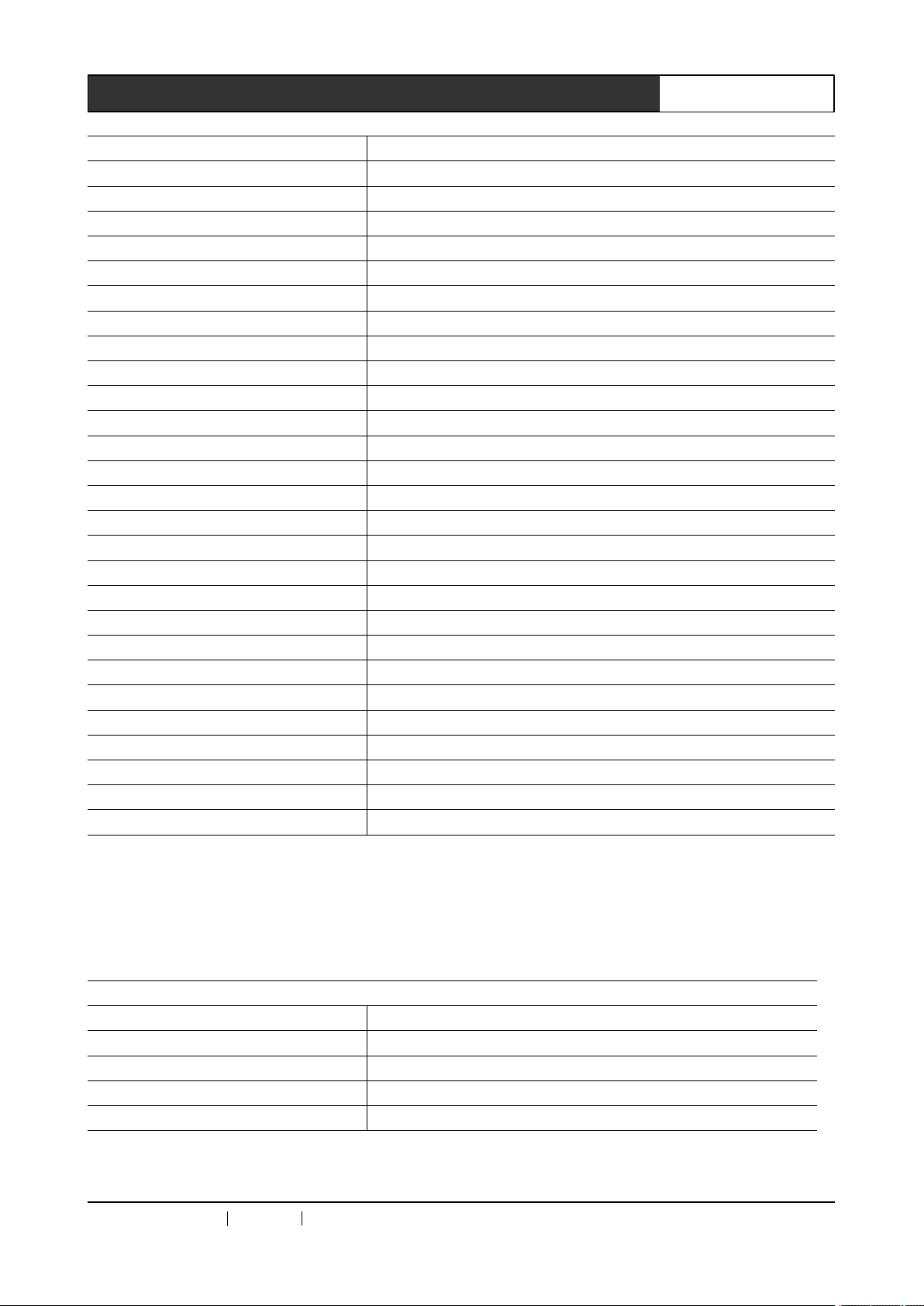
tuning, except that “ key operate: ” is added before the command, and both share the same function
description. E.g.:
4.3
4.3
4.3
4.3 Output
format: $X->Y! X: Output num
CREATOR CHINA 20
Audio
Audio
Audio Tuning
The audio tuning return command in the panel key operation is similar with the command for audio
format: key operate: #X->YdB! X: Input num
Command Function description
key operate: #1->+00.0dB! YpbPr YC input volume set as +00.0dB
key operate: #2->-01.0dB! YpbPr YC input volume set as -01.0dB
key operate: #3->+05.0dB! CV input volume set as +05.0dB
key operate:...... ......
Output
Output
Output Resolution
Tuning
Tuning
Tuning Return
Resolution
Resolution
Resolution Commands
Return
Return
Return Command
11
- 08 WWW.CREATOR199 7 .COM
Command
Command
Command
Commands
Commands
Commands
Y:
output format
Y:
Volume value
Page 20
Command Function description
$1->720p60! 3G-SDI output 720p60
$1->720p59.94! 3G-SDI output 720p59.94
$1->720p50! 3G-SDI output 720p50
$1->720p60! 3G-SDI output 720p60
$1->1080i50! 3G-SDI output 1080i50
$1->1080i60! 3G-SDI output 1080i60
$1->1080i59.94! 3G-SDI output 1080i59.94
$1->1080p30! 3G-SDI output 1080p30
$1->1080p29.97! 3G-SDI output 1080p29.97
$1->1080p25! 3G-SDI output 1080p25
$1->1080p24! 3G-SDI output 1080p24
$1->1080p23.98! 3G-SDI output 1080p23.98
$1->1080p60! 3G-SDI output 1080p60
$1->1080p59.94! 3G-SDI output 1080p59.94
$1->1080p50! 3G-SDI output 1080p50
$2->800x600x60HZ! DVI HDMI output 800x600x60HZ
$2->1024x768x60HZ! DVI HDMI output 1024x768x60HZ
$2->1152x864x75HZ! DVI HDMI output 1152x864x75HZ
$2->1280x720x60HZ! DVI HDMI output 1280x720x60HZ
$2->1280x768x60HZ! DVI HDMI output 1280x768x60HZ
$2->1280x960x60HZ! DVI HDMI output 1280x960x60HZ
$2->1280x1024x60HZ! DVI HDMI output 1280x1024x60HZ
$2->1360x768x60HZ! DVI HDMI output 1360x768x60HZ
$2->1366x768x60HZ! DVI HDMI output 1366x768x60HZ
$2->1440x900x60HZ! DVI HDMI output 1440x900x60HZ
$2->1600x1200x60HZ! DVI HDMI output 1600x1200x60HZ
$2->1920x1080x60HZ! DVI HDMI output 1920x1080x60HZ
13Professional SDI/DVI/HDMI Switch Scaler User ’ s Manual
4.3.1
4.3.1
4.3.1
4.3.1 Output
output resolution setting, except that “ key operate: ” added before the command, and both share the
same function description. E.g.:
CREATOR CHINA 20
Output
Output
Output Resolution
The output resolution return command in the panel key operation is similar with the command for
format: key operate: $X->Y! X: Output num
Command Function description
key operate: $1->1080p59.94! 3G-SDI output 1080p59.94
key operate: $2->800x600x60HZ! DVI HDMI output 800x600x60HZ
key operate: $2->1024x768x60HZ! DVI HDMI output 1024x768x60HZ
key operate:...... ......
Resolution
Resolution
Resolution Return
11
- 08 WWW.CREATOR199 7 .COM
Return
Return
Return Commands
Commands
Commands
Commands
Y:
output format
Page 21
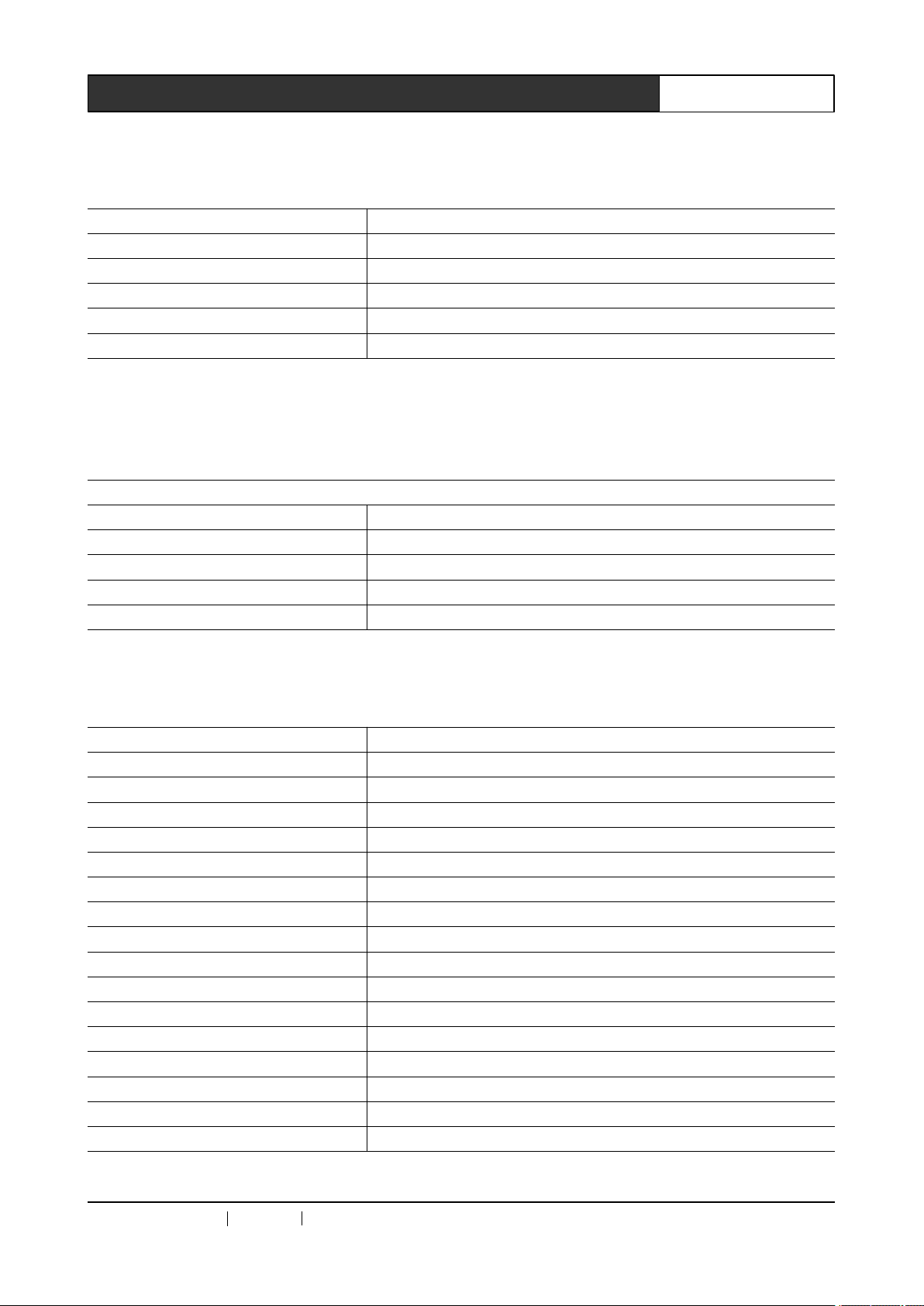
4.4
Gamma
4.4
Gamma
4.4
4.4 Gamma
Gamma Value
format: @gamma->X! X: gamma value range 0.4~1.6 stepping as 0.2
Command Function description
@gamma->0.6! Set the output gamma value as 0.6
@gamma->0.8! Set the output gamma value as 0.8
@gamma->1.0! Set the output gamma value as 1.0
@gamma->1.2! Set the output gamma value as 1.2
@gamma->1.4! Set the output gamma value as 1.4
Value
Value
Value Setting
Setting
Setting
Setting Command
Command
Command
Command
14Professional SDI/DVI/HDMI Switch Scaler User ’ s Manual
4.4.1
4.4.1
4.4.1
4.4.1 Gamma
for gamma value setting, except that “ key operate: ” is added before the command. Both share the same
function description, e.g.
4.5
4.5
4.5
4.5 Contrast
format: &ACE->X! X: ACE Strength value range 00~15 stepping as 01
Gamma
Gamma
Gamma Value
The gamma value setting return command in the panel key operation is similar with the command
format: key operate: @gamma->X! X: gamma value range 0.4~1.6 stepping as 0.2
Command Function description
key operate: @gamma->0.6! Set the output gamma value as 0.6
key operate: @gamma->0.8! Set the output gamma value as 0.8
key operate: @gamma->1.0! Set the output gamma value as 1.0
key operate:...... ......
Contrast
Contrast
Contrast Setting
Command Function description
&ACE->00! Set ACE Strength value as 00
&ACE->01! Set ACE Strength value as 01
&ACE->02! Set ACE Strength value as 02
&ACE->03! Set ACE Strength value as 03
&ACE->04! Set ACE Strength value as 04
&ACE->05! Set ACE Strength value as 05
&ACE->06! Set ACE Strength value as 06
&ACE->07! Set ACE Strength value as 07
&ACE->08! Set ACE Strength value as 08
&ACE->09! Set ACE Strength value as 09
&ACE->10! Set ACE Strength value as 10
&ACE->11! Set ACE Strength value as
&ACE->12! Set ACE Strength value as 12
&ACE->13! Set ACE Strength value as 13
&ACE->14! Set ACE Strength value as 14
&ACE->15! Set ACE Strength value as 15
Value
Value
Value Setting
Setting
Setting
Setting Return
Setting
Setting
Setting Command
Return
Return
Return Command
Command
Command
Command
Command
Command
Command
11
CREATOR CHINA 20
11
- 08 WWW.CREATOR199 7 .COM
Page 22
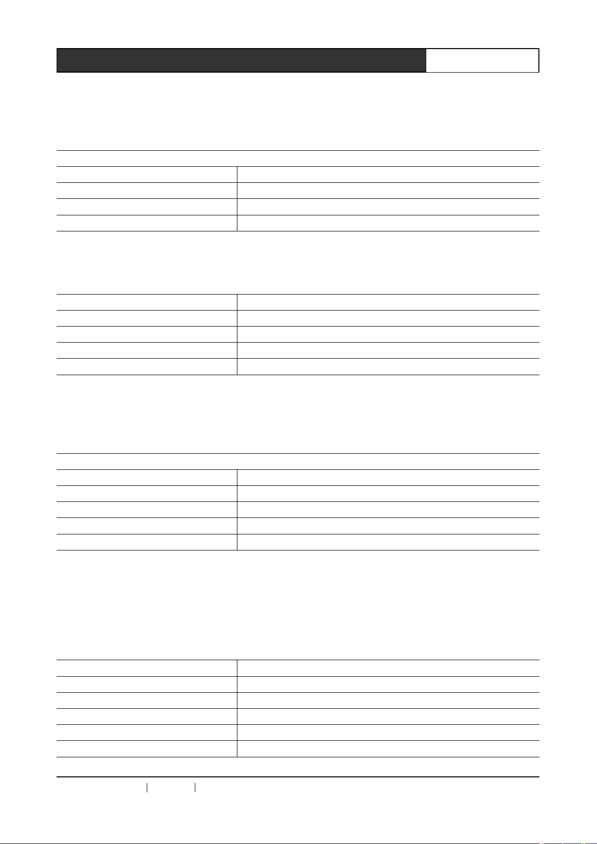
15Professional SDI/DVI/HDMI Switch Scaler User ’ s Manual
4.5.1
4.5.1
4.5.1
4.5.1 Contrast
contrast setting, except that “ key operate: ” is added before the command, and both share the same
function description. E.g.:
4.6
4.6
4.6
4.6 Detail
format: %DetailLevel->X! X: Detail Level range 000~255 stepping as 001 . Example :
Contrast
Contrast
Contrast Setting
The contrast setting return command in the panel key operation is similar with the command for
format: key operate: &ACE->X! X: ACE Strength value range 00~15 stepping as 01
Command Function description
key operate: &ACE->02! Set ACE Strength value as 02
key operate: &ACE->03! Set ACE Strength value as 03
key operate:...... ......
Detail
Detail
Detail Enhancement
Command Function description
%DetailLevel->000! Set Detail Level value as 000
%DetailLevel->123! Set Detail Level value as 123
%DetailLevel->222! Set Detail Level value as 222
%DetailLevel->255! Set Detail Level value as 255
Setting
Setting
Setting Return
Enhancement
Enhancement
Enhancement Setting
Return
Return
Return Command
Command
Command
Command
Setting
Setting
Setting Command
Command
Command
Command
4.6.1
4.6.1
4.6.1
4.6.1 Detail
enhancement setting command, except that “ key operate: ” is added before the command, and both
share the same function description. E.g.:
4.7
4.7
4.7
4.7 Image
format: ^offset->X,Y ,Z! X: Red offset range -1023~+1023 stepping is 0001
Example:
Detail
Detail
Detail Enhancement
The detail enhancement setting return command in the panel key operation is similar with the detail
format: key operate: %DetailLevel->X! X: Detail Level range 000~255 stepping is 001
Command Function description
key operate: %DetailLevel->123! Set Detail Level value as 123
key operate: %DetailLevel->222! Set Detail Level value as 222
key operate: %DetailLevel->255! Set Detail Level value as 255
key operate:...... ......
Image
Image
Image Color
Command Function description
^offset->+0000,+0000,+0000! Set red Offset +0000, blue Offset +0000, green Offset +0000
^offset->+0010,+0020,+0030! Set red Offset +0010, blue Offset +0020, green Offset +0030
^offset->+0400,+0500,+0600! Set red Offset +0400, blue Offset +0500, green Offset +0600
^offset->+1000,+1000,+1000! Set red Offset +1000, blue Offset +1000, green Offset +1000
^offset->+1023,+1023,+1023! Set red Offset +1023, blue Offset +1023, green Offset +1023
Enhancement
Enhancement
Enhancement Setting
Color
Color
Color Offset
Y:
Blue offset range -1023~+1023 stepping is 0001
Z: Green Offset range -1023~+1023 stepping is 0001
Offset
Offset
Offset Setting
Setting
Setting
Setting Return
Setting
Setting
Setting command
Return
Return
Return Command
command
command
command
Command
Command
Command
CREATOR CHINA 20
11
- 08 WWW.CREATOR199 7 .COM
Page 23
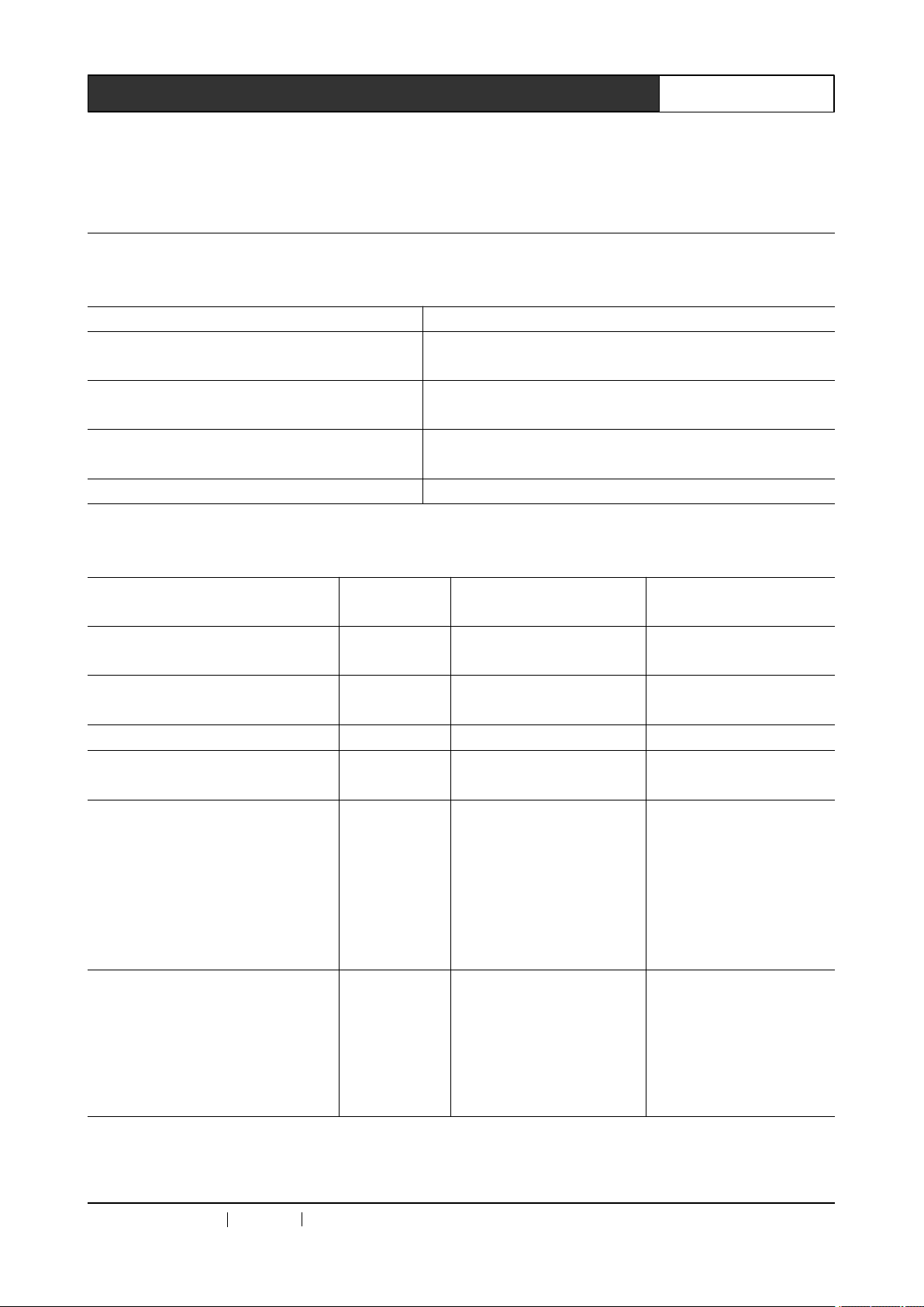
16Professional SDI/DVI/HDMI Switch Scaler User ’ s Manual
4.7.1
4.7.1
4.7.1
4.7.1 Image
setting command, except that “ key operate: ” is added before the command, and both share the same
function description. E.g.:
4.8
4.8
4.8
4.8 Network
Image
Image
Image Offset
The image offset setting return command in the panel key operation is similar with the image offset
format: key operate: ^offset->X,Y ,Z! X: Red offset range -1023~+1023 stepping is 0001
Command Function description
key operate: ^offset->+0000,+0000,+0000!
key operate: ^offset->+0010,+0020,+0030!
key operate: ^offset->+0400,+0500,+0600!
key operate:...... ......
Network
Network
Network Setting
ASCII command
(computer to switch scaler)
<#SPORT[5000]>
<#SIPR[192]. [168]. [0]. [2]>
<#GAR [192]. [168]. [0]. [1]> Set gateway GAR:[192].[168].[0].[1] <# GAR 192. 168. 0. 1>
<#SUBR [255]. [255]. [255]. [0]>
<# SHAR 0x[00]. 0x[11]. 0x[22].
[0x33]. [0x44]. [0x55]>
<#NETDEFAULT>
Offset
Offset
Offset Setting
Setting
Setting
Setting Return
Y:
Blue offset range -1023~+1023 stepping is 0001
Z: Green Offset range -1023~+1023 stepping is 0001
Setting
Setting
Setting Command
Command
Command
Command
Return
Return
Return Command
Command
Command
Command
Command
function
Set network
port number
Set network
IP
Set subnet
mask
Set MAC
address
(MAC
address is in
the
hexadecimal
system)
Restore the
default value
of the
network
factory
configuration
Set red Offset +0000, blue Offset +0000, green Offset
+0000
Set red Offset +0010, blue Offset +0020, green Offset
+0030
Set red Offset +0400, blue Offset +0500, green Offset
+0600
return (switch scaler to
computer)
SPORT: [5000] <#SPORT5000>
SIPR:[192].[168].[0].[2] <#SIPR192. 168. 0. 2>
SUBR:[255].[255].[255].[0]<# SUBR255. 255.255.
0x[00]. 0x[11]. 0x[22].
[0x33]. [0x44]. [0x55]>
NETDEFAULT: [OK] <#NETDEFAULT>
Example
0>
<#SHAR0x00.0x11.0x2
2.0x33.0x44.0x55>
CREATOR CHINA 20
11
- 08 WWW.CREATOR199 7 .COM
Page 24
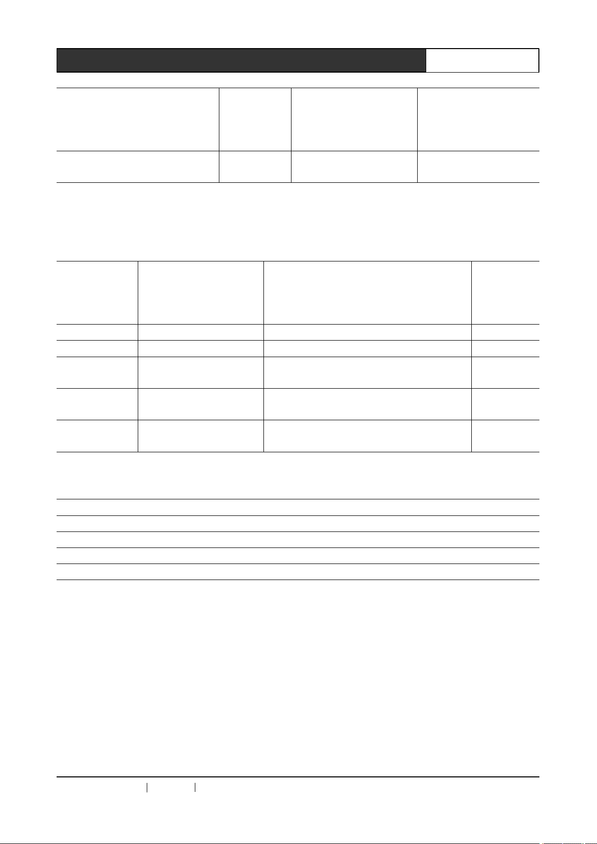
17Professional SDI/DVI/HDMI Switch Scaler User ’ s Manual
Set network
parameters
value
wrongly
Set network
successfully
Remarks:
Remarks:
Remarks:
Remarks: When
when the network is set successfully, the system will return as “ NETSET:OK ” .
4.9
4.9
4.9
4.9 Network
ASCII
command
(computer to
switch scaler)
<^SPORT> Inquire working port SPORT:[X12] <^SPORT>
<^SIPR> Inquire IP SIPR:[X12].[X13].[X14].[X15] <^SIPR>
<^SUBR>
<^GAR>
<^SHAR>
When
When
When network parameters value is wrongly set, the system will return as “ Out of range! ” ;
Network
Network
Network Inquiry
Inquiry
Inquiry
Inquiry Command
Command function Return (switch scaler to computer) Example
Inquire current network
subnet mask number
Inquire current network
gateway number
Inquire current network
MAC address number
Command
Command
Command
Out of range!
NETSET:OK
SUBR:[X12].[X13].[X14].[X15] <^SUBR>
GAR:[X12].[X13].[X14].[X15] <^GAR>
SHAR:[X12].[X13].[X14].[X15].[X16].[X17] < ^SHAR>
4.10
4.10
4.10
4.10 Network
Note: you need to restart the switch scaler to enable all the set network parameters.
4.11
4.11
4.11
4.11 Equipment
Command
Command
Command
Command
command: ~read stauts!
Reply format as follows:
Input: VGA
Input Format: NO INPUT
Output: DVI
DVI Output Format: 1024x768x60HZ
Network
Network
Network Interface
Switch scaler’s network port number: 5000
Switch scaler’s network IP: 192.168.0.2
Switch scaler’s network gateway number: 192.168.0.1
Switch scaler’s network subnet mask: 255.255.255.0
Switch scaler’s network MAC address: 0x00.0x11.0x22.0x33.0x44.0x55;
Equipment
Equipment
Equipment Status
Interface
Interface
Interface Default
Status
Status
Status Reading
Default
Default
Default Parameters
Reading
Reading
Reading
Parameters
Parameters
Parameters
CREATOR CHINA 20
11
- 08 WWW.CREATOR199 7 .COM
Page 25

HDMI Output Format: 1024x768x60HZ
3G-SDI Output Format: 720p60
YPbPr YC Input Volume: +00.0dB
CV Input Volume: +00.0dB
VGA Input Volume: +00.0dB
DVI Input Volume: +00.0dB
Gamma LUT : 1.0
Adaptive Contrast: 00
Detail Level: 000
ImageColor Red Offset: +0000
ImageColor Blue Offset: +0000
ImageColor Green Offset: +0000
Machine Temperature: +36.5 ℃
Software Edition: Ver 1.001
18Professional SDI/DVI/HDMI Switch Scaler User ’ s Manual
4.12
4.12
4.12
4.12 Factory
Restoring
Restoring
Restoring
Restoring Command
Restore factory default setting command (but not
restoring network parameters):
format:/Reset Settings!
Factory default setting value:
Input: DVI
Input Format: NO INPUT
Output: DVI
DVI Output Format: 1024x768x60HZ
HDMI Output Format: 1024x768x60HZ
3G-SDI Output Format: 720p60
YPbPr YC Input Volume: +00.0dB
CV Input Volume: +00.0dB
VGA Input Volume: +00.0dB
DVI Input Volume: +00.0dB
Gamma LUT : 1.0
Adaptive Contrast: 00
Detail Level: 000
ImageColor Red Offset: +0000
ImageColor Blue Offset: +0000
ImageColor Green Offset: +0000
Factory
Factory
Factory Default
Default
Default
Default Setting
Command
Command
Command
Setting
Setting
Setting
CREATOR CHINA 20
11
- 08 WWW.CREATOR199 7 .COM
Page 26
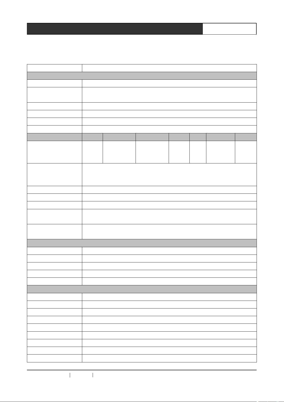
19Professional SDI/DVI/HDMI Switch Scaler User ’ s Manual
Chapter
Chapter
Chapter
Chapter 5
Model no.Technical Specs CR-SC-390
Video
Gain 0 dB
Pixel bandwidth
Differential phase I/OS
Differential phase error 0.1 ° , 3.58-4.43 MHz
Differential gain error time 0.1%, 3.58-4.43 MHz
Signal type VGA, S-video, COMP separate video (YPbPr/YCbCr), complex video (CVBS), DVI, HDMI.
Video input CV S-Video VGA COMP DVI HDMI 3G-SDI
Interface
Signal strength
Min./max. level analog signal: -2V/+2V
Impedance analog signal: 75 Ω HDMI/DV I signal: 50 Ω
Echo loss < -30dB@5MHz
Horizontal frequency
response
Vertical frequency
response
VGA video input
Interface DB-15
Min./max. level -2.0V/ +2.0V
Impedance 75 Ω
Echo loss
DC compensation max. ± 5mV
VGA Synchronous signal
Input/output signal type RGBHV, RGBS, RGsB, RsGsBs, complex video, component video, separate video.
Video system NTSC 3.58, NTSC 4.43, PAL, SECAM
Input level 0.5V- 5.0V p-p,: 4.0V p-p normal
Output level AGC-TTL: 5Vp-p, unterminated
Input impedance 510 Ω
Output impedance 75 Ω
Max. transmission delay horizontal:90ns vertical:160ns
Max. up/down time 4ns
Polarity Positive or negative (completely the same as input
Video, S-video, YPbPr/YCbCr: 6MHz, VGA video: 250 MHz, DVI video: 165MHz,
HDMI: 165MHz 3G-SDI:2.970Gb/s
< 1.28 ° , 3.58 MHz
BNC
connect
or
1V p-p: Y component video, S-video, complex video;
0.7V p-p: VGA (computer signal);
0.3V p-p: separate video, S-video C, HDMI/DVI video.
30-200KHZ
20Hz-240Hz
< -40dB@5MHz
5
Technical
5
Technical
5 Technical
Technical Parameters
BNC
connector
15-pin HD
female
interface
Parameters
Parameters
Parameters
BNC
connect
or
DVI-
HDMI-A
D
F emale
connector
BNC
connect
or
CREATOR CHINA 20
11
- 08 WWW.CREATOR199 7 .COM
Page 27
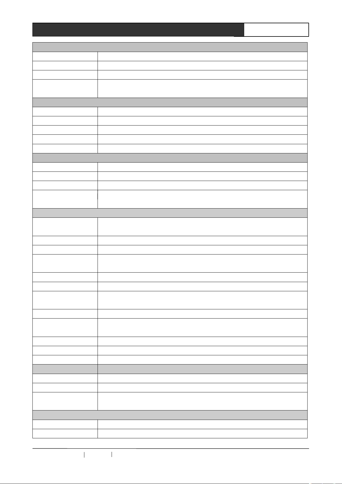
20Professional SDI/DVI/HDMI Switch Scaler User ’ s Manual
DVI Video Signal Output
Interface DVI-D interface
Min./max. level T.M.D.S+/-0.4Vpp
impedance 50 Ω
Recommended max.
transmission distance
3G-SDI Output
Interface BNC mother connector
Impedance 75 Ω
Echo loss
Max. DC compensation ± 5Mv
Output impedance 75 Ω
HDMI output
Interface HDMI-A mother interface
Min./max. level T.M.D.S. 2.9V/3.3V
Impedance 50 Ω
Recommended max.
output distance
Audio Signal
Input/output interface 4-way 3.8mm phoenix interface stereo audio input, 1-way 3.8mm phoenix interface stereo
Gain 0 dB
Frequency response 20 Hz ~ 20 kHz,
Total
Harmonic Distortion
+ Noise
Signal/Noise Ratio (S/N)
Stereo Crosstalk > 80dB @ 1 kHz
Common Mode Rejection
Ratio (CMRR)
Signal type Stereo (Non-end-to-end audio)
Impedance
Max. input level +19.5dBu, (balance or/ non-balance way of connection)
Gain error ± 0.1dB @20 Hz ~ 20 kHz
Max. output level +19.5dBu, (balance or/ non-balance way of connection)
Control
Control
Control
Control Type
Serial control interface RS-232, 9-pin mother D-type interface RS-485
Baud rate and protocol Baud rate: 9600, data bit: 8 bit, stop bit: 1, no parity check bit
Serial control port
structure
Specification
Specification
Specification
Specification
Power 100VAC-240VAC 50/60 Hz, automatically adaptable to international power
Storage temperature -40 ° C ~ +80 ° C
Type
Type
Type Network
Less than 7 meters, when at 1920X1080@60 (Recommend to use the certified DVI
professional cables, such as Molex TM cables)
< -15dB,DC@1MHz to 1.5GHz
Less than 10 meters, when at 1920X1080@60 (Recommend to use the certified HDMI
professional cables, such as Molex TM cables)
audio output
0.05% @ 1 kHz (under the rated voltage)
> 58dB
> 75dB @: 20 Hz ~ 20 kHz
input: >10 k Ω (balance or/ non-balance way of connection)
output: 50 Ω (non-balance way of connection), 100 Ω (balance way of connection)
Network
Network
Network Control
2 = TX, 3 = RX, 5 = GND
Control
Control
Control
CREATOR CHINA 20
11
- 08 WWW.CREATOR199 7 .COM
Page 28
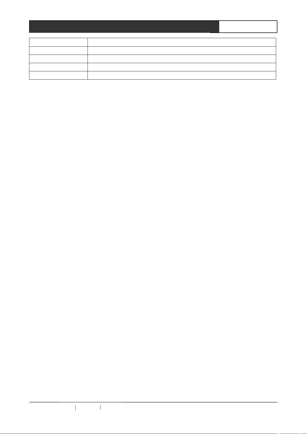
Storage humidity 10% ~ 90%
Operating temperature
Operating humidity
Housing Dimension 1U
Product Weight 1.9kg
-20 ° C ~ +70 ° C
10% ~ 70%
21Professional SDI/DVI/HDMI Switch Scaler User ’ s Manual
CREATOR CHINA 20
11
- 08 WWW.CREATOR199 7 .COM
Page 29

Page 30

CREATOR CORPORATION (CHINA)
Copyright by CREATOR
Last Revision: 08/2011
 Loading...