


Digital Conference System

U
U
s
s
e
e
r
r
’
’
s
s
M
M
a
a
n
n
u
u
a
a
l
l
o
o
f
f
I
I
n
n
t
t
e
e
l
l
l
l
i
i
g
g
e
e
n
n
t
t
D
D
i
i
g
g
i
i
t
t
a
a
l
l
C
C
o
o
n
n
f
f
e
e
r
r
e
e
n
n
c
c
e
e
S
S
y
y
s
s
t
t
e
e
m
m
V2.0
CREATOR CHINA
CREATOR CORPORATION

Meaning of the Icons
■ Safety Instruction
Symbols are used in the Manual and devices, referring to the possible risk to users or others,as well as
the damage to property, for helping you to safely and properly use the devices. The instruction and the
implications are as follows. Please make sure your correct understanding of these instructions before
using the Manual.
To remind user to conduct according to the attached
operation and maintenance instructions. If ignore these
information, death or injury could possibly happen.
To remind the user that the risky uninsulated voltage in the
device could caused electric shock to human.
CE authentication indicates the product is in line with the
EU safety regulation, and for assurance of safety use.
SGS Authentication indicates the product has reached the
QC standard of the global-biggest Swiss universe
surveyor.
This product has acquired the ISO9001 International
Quality Authentication (Authentication authority: Germany
Rheinland TUV)
Caution: To avoid electric shock, please don't open the
case, nor put the useless parts in it. Please contact with
qualified service staff.
■ General Information Instruction
List the situation could cause unsuccessful operation or
setup, and relevant information needed to notice.

Important Notices
Caution
To ensure the device in reliable use and
personal safety, please abide by the following
items when in installation, use and maintenance:
Notice in installation
◆ Please DO NOT use the product in following
places: the places with dust, oily smoke,
electrical conductive dust, corrosive gas,
inflammable gas; the places with high
temperature, due, rain and wind exposures; the
places endangered by shock and vibration.
Electric shock, fire and incorrect operation could
also cause damage and deterioration to the
product.
◆ When conducting screw drilling and wiring
process, DO NOT let metal irons and wire lead
drop into the controller and air vent, which could
possibly cause fire, failure and accidental
operation.
◆ After finishing the installation, it is necessary
to ensure there is no foreign matter including the
packing material like contact paper on the
ventilation surface, otherwise, it could cause
poor heat dissipation while running, as well as
fire, failure and accidental operation.
◆ Avoid conducting wiring and plugging in/out
cable socket with electricity, otherwise, electric
shock, circuit damage could easily happen.
◆ Installation and wiring should be firm and
reliable. Poor contact could cause malfunction.
◆ With regard to the application situations with
strong interference, shielded cable should be
used for the input and output of HF signal, to
improve the anti-interference performance of the
system.
Note in Wiring
◆ Installation and wiring shouldn't be conducted
until external electric power is cut off, otherwise,
electric shock or device damage could happen.
◆ The product is grounded by the earth lead of
the power cable. To avoid electric shock, the
earth lead is necessary to be connected with the
ground. Before making connection with the
output end or input end of the product, please
ensure it is correctly grounding.
◆ Upon finish wiring, remove the sundries.
Please cover up the terminal plate for avoiding
electric shock.
Note for Operation and Maintenance
◆ Please DO NOT touch the terminal when with
electricity, otherwise, electric shock could
happen.
◆ Don't clean up and screw the terminal tight
before power is off. Such operation could cause
electric shock when with electricity.
◆ Please turn off the power before connecting or
disconnecting the communication signal cable,
peripheral modules or control units, otherwise,
device could be damaged and accidental
operation could happen.
◆ Please DO NOT disassemble the device, so
as to avoid internal electric components damage.
◆ It is necessary to read through the Manual and
fully ensure the safety, before altering the
program, trial running, starting and stopping
operation.
Note for declaration of worthless.
When declaring of worthless, please note

◆ Explosion of electrolytic capacitor on the
circuit board could happen when burning it.
◆ please classify and dispose it. Don't dispose it
into household garbage.
◆ please deal it as industrial waste, or in
accordance with local environmental protection
regulation.

Preface
User’s Manual of Intelligent Digital Conference System primarily introduce the operation of
CR-M4101,CR-M4201,CR-ME4000,CR-M4104A1,CR-M4102A2,CR-M4104A2,CR-M4202A2,CR-M42
04A2,CR-M4102B,CR-M4104B,CR-M4202B2,CR-M4204B2,CR-M4202G,CR-M4204G,CR-M4102C1,
CR-M4104C1,CR-M4102C4,CR-M4104C4,CR-M4102D2,CR-M4104D2,CR-TP4104D,CR-M4102E,C
R-M4104E,CR-M4102F,CR-M4104F,CR-MC4032B,CR-MC4034B,CR-M4103E3,CR-TP4102,CR-IR20
00-12,CR-IR2001-12,CR-IR2002-12,CR-V101*, MVC-4200, CR-T1000, key parameters and trouble
shootings.
The Manual serves as user's operation instruction, rather than for maintenance service purpose.
Since the date of release, any function or relevant parameter alteration will be in supplement instruction.
Please refer to the manufacturer or dealers for inquiry.
CREATOR Electronics own the copyright of the Manual. Without permission, any unit or person
shall not take part or total of the Manual for business purpose.
The copyright of the Manual is protected by Copyright Law of People’s Republic of China and other
Intellectual Property Law. Without written permission, any copy or distribution is prohibited.

Index
Chapter 1 Overview ................................................................................................................................... 1
1.1 System Features ........................................................................................................................... 1
1.2 System Devices ............................................................................................................................ 2
1.3 Controller Installation .................................................................................................................... 2
Chapter 2 DCS Control System ................................................................................................................ 3
2.1 Conference Controlling Controller ................................................................................................ 3
2.1.1 Panel Functions Instruction............................................................................................. 3
2.1.2 Functions and Features .................................................................................................. 5
2.1.3 Port Pin Instruction .......................................................................................................... 5
2.2 Conference Extended Controller .................................................................................................. 6
2.2.1 Panel Functions Instruction............................................................................................. 6
2.2.2 Functions and Features .................................................................................................. 7
2.3 ID Setup in Conference Unit ......................................................................................................... 7
2.4 System Connection Diagram ........................................................................................................ 7
2.5 Technical Parameters ................................................................................................................... 8
Chapter 3 DCS Discussion Unit ................................................................................................................ 9
3.1 Type of DCS Discussion Unit ........................................................................................................ 9
3.2 CR-M4104A1 Discussion Unit .................................................................................................... 10
3.2.1 Panel Functions Instruction........................................................................................... 10
3.2.2 Functions and Features ................................................................................................ 10
3.3 CR-M4102/4A2 Chairman/Delegate Unit ................................................................................... 11
3.3.1 Panel Functions Instruction........................................................................................... 11
3.3.2 Functions and Features ................................................................................................ 12
3.4 CR-M4202/4A2 Chairman/Delegate Unit ................................................................................... 12
3.4.1 Panel Functions Instruction........................................................................................... 12
3.4.2 Functions and Features ................................................................................................ 13
3.5 CR-M4102/4B Chairman/Delegate Unit ..................................................................................... 14
3.5.1 Panel Functions Instruction........................................................................................... 14
3.5.2 Functions and Features ................................................................................................ 14
3.6 CR-M4202/4B2 Chairman/Delegate Unit ................................................................................... 15
3.6.1 Panel Functions Instruction........................................................................................... 15
3.6.2 Functions and Features ................................................................................................ 16
3.7 CR-M4202/4G Chairman/Delegate Unit ..................................................................................... 17

3.7.1 Panel Functions Instruction........................................................................................... 17
3.7.2 Functions and Features ................................................................................................ 18
3.8 Embedded Unit ........................................................................................................................... 18
3.8.1 Panel Functions Instruction........................................................................................... 18
3.8.2 Functions and Features ................................................................................................ 19
3.9 CR-M4102/4D2 Chairman/Delegate Unit ................................................................................... 20
3.9.1 Panel Functions Instruction........................................................................................... 20
3.9.2 Functions and Features ................................................................................................ 21
3.10 CR-TP4102D Chairman Unit .................................................................................................... 22
3.10.1 Panel Functions Instruction......................................................................................... 22
3.10.2 Touch Screen Functions Instruction ............................................................................ 23
3.10.3 Functions and Features .............................................................................................. 25
3.11 CR-TP4102D Chairman Unit..................................................................................................... 26
3.11.1 Panel Functions Instruction ......................................................................................... 26
3.11.2 Functions and Features .............................................................................................. 27
3.12 CR-M4102/4F Chairman/Delegate Unit .................................................................................... 27
3.12.1 Panel Functions Instruction......................................................................................... 27
3.12.2 Functions and Features .............................................................................................. 28
3.13 Connection Diagram ................................................................................................................. 29
3.13.1 Diagram of T-shaped Connection Mode ..................................................................... 29
3.13.2 Diagram of Hand-in-hand Connection Mode .............................................................. 29
3.13.3 Diagram of Embedded Unit Connection ..................................................................... 29
3.14 Technical Parameters ............................................................................................................... 30
Chapter 4 DCS Simultaneous Interpretation ........................................................................................... 32
4.1 CR-M4103E3 Interpretation Unit ................................................................................................ 32
4.1.1 Panel Functions Instruction........................................................................................... 32
4.1.2 Monitor Description ....................................................................................................... 33
4.1.3 Menu Setup ................................................................................................................... 33
4.1.4 Monitoring Unit .............................................................................................................. 35
4.1.5 Functions and Features ................................................................................................ 35
4.2 Technical Parameters ................................................................................................................. 36
4.3 Diagram of System Connection .................................................................................................. 37
Chapter 5 DCS Infrared Voice Distribution System ................................................................................ 38
5.1 Products and Devices ................................................................................................................. 38
5.2 CR-IR2000-12 Infrared Transmission Controller ........................................................................ 38
5.2.1 Panel Functions Instruction........................................................................................... 38
5.2.2 Functions and Features ................................................................................................ 39
5.2.3 Technical Parameters ................................................................................................... 39
5.3 CR-IR2001-12 Infrared Radiation Panel ..................................................................................... 39

5.3.1 Panel Functions Instruction........................................................................................... 39
5.3.2 Functions and Features ................................................................................................ 40
5.3.3 Technical Parameters ................................................................................................... 40
5.4 CR-IR2002-8/12 Infrared Receiving Unit .................................................................................... 40
5.4.1 Panel Functions Instruction........................................................................................... 40
5.4.2 Functions and Features ................................................................................................ 40
5.4.3 Technical Parameters ................................................................................................... 41
5.5 Diagram of System Connection .................................................................................................. 41
hapter 6 DCS Camera Tracing ................................................................................................................ 42
6.1 Products and Devices ................................................................................................................. 42
6.2 MVC-4200 Camera Tracing Mixing Controller ............................................................................ 42
6.2.1 Panel Functions Instruction........................................................................................... 42
6.2.2 Functions and Features ................................................................................................ 43
6.2.3 Technical Parameters ................................................................................................... 43
6.3 CR-V1011/V1012 High-speed Camera....................................................................................... 43
6.3.1 Functions and Features ................................................................................................ 43
6.3.2 Technical Parameters ................................................................................................... 44
6.4 Diagram of System Connection .................................................................................................. 45
Chapter 7 DCS Telephone Conference .................................................................................................. 46
7.1 Product s and Devices ................................................................................................................ 46
7.2 CR-T1000Panel Functions Instruction ........................................................................................ 46
7.3 Functions and Features .............................................................................................................. 46
7.4 Technical Parameters ................................................................................................................. 47
7.5 Diagram of System Connection .................................................................................................. 47
Chapter 8 Accessories ............................................................................................................................ 48
8.1 CR-P2 Headset(Without MIC) ............................................................................................. 48
8.1.1 Product Profile ............................................................................................................... 48
8.1.2 Technical Parameters ................................................................................................... 48
8.2 CR-P4 Headset with MIC ............................................................................................................ 48
8.2.1 Product profile ............................................................................................................... 48
8.2.2 Technical Parameters ................................................................................................... 48
8.3 Cable Installation ......................................................................................................................... 48
8.4 CR-M5KL415 Turning 415mm MIC Stand .................................................................................. 49
8.5 CR-CT10 T-shaped Connector ................................................................................................... 49
8.6 CR-CT20 Conference Desktop Socket ....................................................................................... 49
8.7 CR-CT30 Jumping Conference Socket ...................................................................................... 49

8.8 CR-CT50 8-pin Aviation Connector ............................................................................................ 49
8.9 CR-HMP24 Extended Power Supply .......................................................................................... 49
8.10 CR-link20 Signal Amplifier ........................................................................................................ 50
Chapter 9 Annex ...................................................................................................................................... 51
9.1 Code Specification ...................................................................................................................... 51

CREATOR CHINA 2010-09 WWW.CREATOR1997.COM
1
User’s Manual of Intelligent Digital Conference System
Chapter 1 Overview
CREATOR intelligent digital conference
system is a high-tech professional products
series after the launch of multimedia central
control products and audio and video matrix
products, including discussion and Discussion,
simultaneously interpretation, infrared voice
distribution, remote telephone conference, voting,
camera tracing etc.
Inherited with the idea of complete system
integrating resolution as CREATOR has been
advocating all along, CREATOR making close
compatibility between two different system of
DCS (digital conference system) and MCS
(multimedia central system), delivering an
complete intelligent conference system resolution
comprising of CREATOR products.
This Manual is made for the controlling
controller of CREATOR intelligent digital
conference system, Discussion unit, camera
tracking system, telephone conference system
and infrared voice distribution system.
1.1 System Features
◆ Security
For any conference, the priority is to ensure
the security of every delegate presented.
1) Conference unit adopt passive device,
with power supply from the controller;
2) All parts are adopted with the materials
with security certificate ;
3) Anti-static.
◆ Anti-interference
In communication and application system,
unique technical processing is adopted, for
preventing from external radiation interference.
◆ Complete Function
Intelligent digital conference system
integrates with discussion, voting, simultaneously
interpretation as a whole. Press the keys on the
unit to choose conference discussion, conference
voting and voice channel.
◆ Clear Voice Transportation
Adopting quality sound pick-up, built-in
speaker, high-fidelity speaker for ensuring to have
clear transportation and receiving when each
delegate is giving a Discussion.
◆ Reliable Encryption System
Adopting unique secure encryption measure
to ensure the privacy of the conference and the
content of the whole conference won’t be leaked
or tapped malignantly.
◆ Good for Maintenance, Easy Operation
1) The whole conference system is easy for
operation. The system is connected in the way of
hand-in-hand or T-shaped. The installation is very
simple. In conference, participant may just press
on the Discussion key to give a Discussion, with
adjustable volume.
2) After taking short-term training, user can
maintain the system, without very professional
technique needed.
◆ Extendibility
As the number of participants of the
conference vary, the extendibility of the
conference system becomes increasingly
important. CREATOR intelligent conference
system is with simple and reasonable structure,
and strong extendibility.
◆ Various Options
CREATOR intelligent digital conference
system may opt to different conference system
according to different occasions and needs,

CREATOR CHINA 2010-09 WWW.CREATOR1997.COM
2
User’s Manual of Intelligent Digital Conference System
including discussion conference, digital voting
conference system, simultaneous interpretation
system, camera tracing conference system,
telephone conference system etc.
1.2 System Devices
CREATOR intelligent digital conference
system comprises of the following devices:
◆ DCS Control System
Conference Control Controller
CR-M4101、CR-M4201
Conference Extended Controller
CR-ME4000
◆ DCS Discussion Unit
Conference Chairman Unit
CR-M4102A2 、 CR-M4202A2 、 CR-M4102B 、
CR-M4202B2 、 CR-M4202G 、 CR-M4102C1、
CR-M4102C4、 CR-M4102D2、 CR-TP4102D、
CR-M4102E、CR-M4102F
Conference Delegate Unit
CR-M4104A1、CR-M4104A2、CR-M4204A2、
CR-M4104B、CR-M4204B2、CR-M4204G、
CR-M4104C1、 CR-M4104C4、CR-M4104D2、
CR-M4104E、CR-M4104F
Audio Cabinet
CR-MC4032B、CR-MC4034B
◆ DCS Simultaneous Interpretation
CR-M4103E3
◆ Infrared Voice Distribution System
Infrared Transmission Controller
CR-IR2000-12
Infrared Radiation Panel
CR-IR2001-12
Infrared Receiving Unit
CR-IR2002-12
◆ DCS Camera Tracing
Camera tracing mixed controller
MVC- 4200
High-speed Camera
CR-V1011、V1012
◆ DCS Telephone Conference
Telephone Coupler
CR-T1000
◆ DCS Relevant Accessories
Headset
CR-P2、CR-P4
Cable
CR-HL005、CR-HL010、CR-HL020、CR-HL050 、
CR-HL100、CR-HT002、CR-HT005
Other Accessories
CR-M5KL415 Turning MIC stand, CR-CT10
T-shaped connector, CR-CT20 conference
desktop socket, CR-CT30 jumping conference
socket、CR-CT50 8-pin aviation plug、CR-HMP24
extending power supply 、 CR-link20 signal
amplifier
1.3 Controller Installation
The controlling controller of CREATOR
intelligent digital conference system can be
installed into a standard 19-inch cabinet. The
controller is with accessory of a pair of cabinet
installation supports. Please see the following
picture for installation:

CREATOR CHINA 2010-09 WWW.CREATOR1997.COM
3
User’s Manual of Intelligent Digital Conference System
Chapter 2 DCS Control System
2.1 Conference Controlling
Controller
The controlling controller of intelligent digital
conference is an important bridge over
conference units and PC management. Using the
navigation keyboard on the panel, along with the
conference management function of the software,
you may have centralized control on all
conference functions, with a variety of conference
mode options (delegate number option,
Discussion mode option), super extending
function, DSP audio processing, equalizer
module, environmental noise suppressing
technology.
2.1.1 Panel Functions Instruction
CR-M4101 Front Panel:
CR-M4201 Front Panel:
CREATOR CHINA 2010-09 WWW.CREATOR1997.COM
4
User’s Manual of Intelligent Digital Conference System
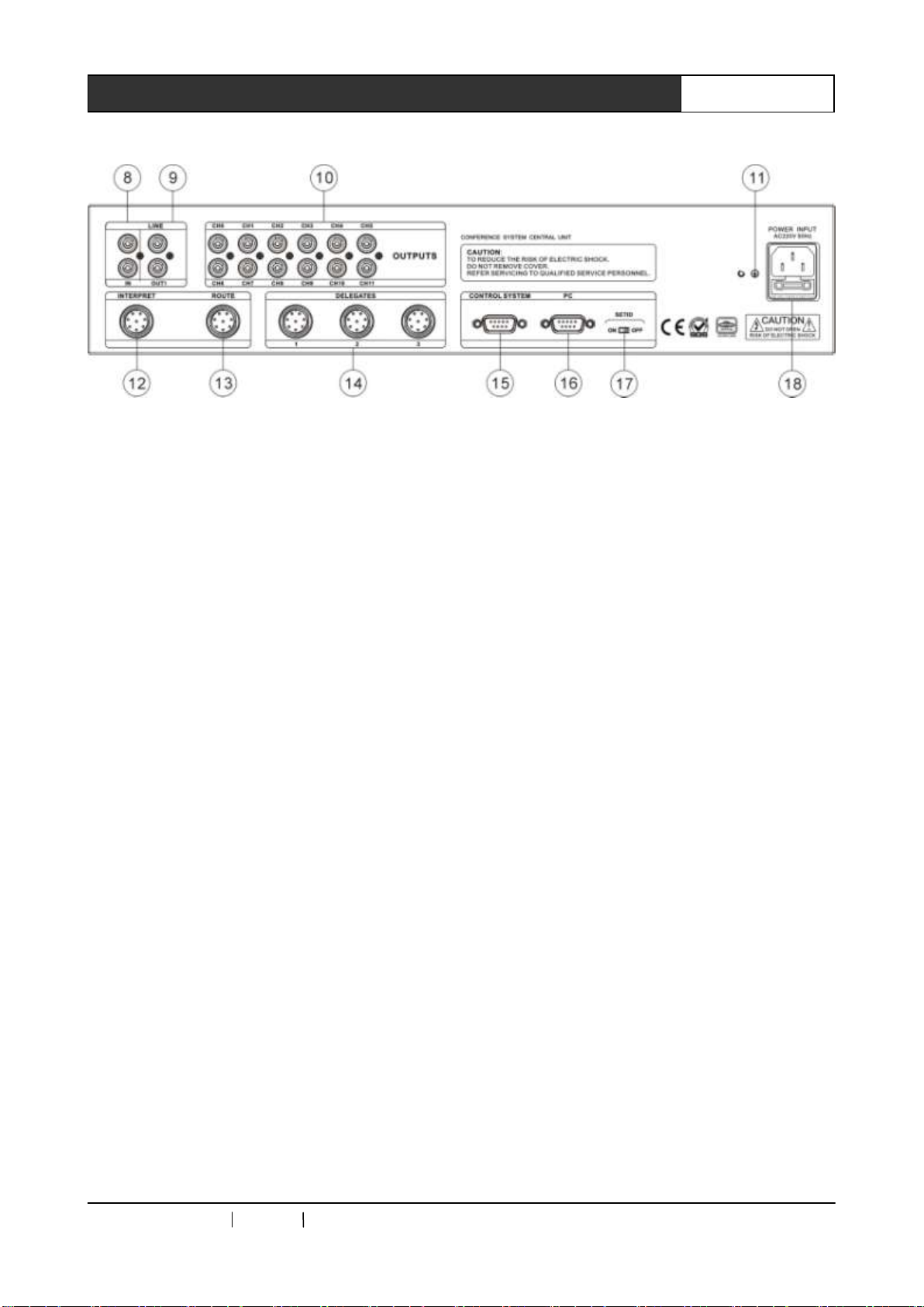
CR-M4101/CR-M4201 Rear Panel:
1) Power Switch
2) MODE
FIFO mode, after reaching the number to
turn on the unit, the earlier-turned-on unit will be
shut down by the unit turned on later.
NORMAL mode,after reaching the number to
turn on the unit, the delegate with request to give
a Discussion will be automatically queue up.
FREE mode, allowing 20 delegate units
online at the same time, without limitation from
the controller. If a delegate request to give a
Discussion, he will automatically queue up
APPLY mode,delegate unit cannot give a
Discussion before getting the approval from
chairman unit or operator.
3) ACTIVE MICRO’S —— Number of speaker
limitation, the delegate units online at the same
time can be set as 1/2/4/6.
4) Audio Effect Setup
A:AFC anti-feedback function setup, press
the AFC key on controller panel to activate
anti-feedback function, at the meantime, the
indicator of the key will be on. Press AFC key
again to turn off the indicator, and shut down
anti-feedback function.
B: ANC noise suppression function setup,
AGC MIC auto-gain control function setup is
operated in the same way as AGC
5) BASS —— Output bass volume adjustment
6) TREBLE——Output treble volume
adjustment.
7) VOLUME ——Output volume adjustment.
8 ) IN ——Cable audio input, such as
background music or remote telephone
conference terminal output
9) OUT ——Connect to audio amplifying system
or recording device, including conference audio
and cable input audio.
10) OUTPUTS ——11+1 channels audio output,
connecting to infrared transmission controller.
11) Connect to grounding pole.
12) INTERPRET ——Connect to 36 interpreter
units at maximum, realizing 11+1 languages
simultaneous interpretation. Interpreter units are
connected hand-in-hand.
13) ROUTE ——Connect to extended controller,
with hand-in-hand serial connections within
CREATOR CHINA 2010-09 WWW.CREATOR1997.COM
5
User’s Manual of Intelligent Digital Conference System
multiple extended controllers.
14) DELEGATES —— Connect to Discussion
unit。
15) CONTROL SYSTEM ——connect to
controller of central controlling system or camera
tracing controller, realize auto-camera and tracing
function.
16) PC ——Connect to PC serial port, realize
conference management function via software.
17) SET ID ——ID setup of Conference unit
18) POWER INPUT ——Power input, support
AC110V/220V
2.1.2 Functions and Features
◆ Conference controlling controller can connect
up to 128 conference units, via conference
extended controller, a set of conference system
can connect to 4096 conference units at
maximum.
◆ Connect to 36 interpreter units at maximum,
realizing the function of 11+1 languages
simultaneous interpretation;
◆ Adopt special 8-pin aviation plug;
◆ Hand-in-hand or T-shaped connection mode;
◆ With audio input port;
◆ With multiple original audio channels output;
◆ Number of speakers limitation; Adjustable
number of 1/2/4/6 for speaking units. Chairman
unit is not limited.
◆ Support a variety of conference modes of FIFO,
NORMAL, FREE and APPLY.
◆ Support auto-camera tracing function;
◆ Hold remote telephone conference along with
telephone coupler;
◆ Support sign-up, voting and data management
function;
◆ The controller can be installed into a standard
19-inch cabinet.
2.1.3 Port Pin Instruction
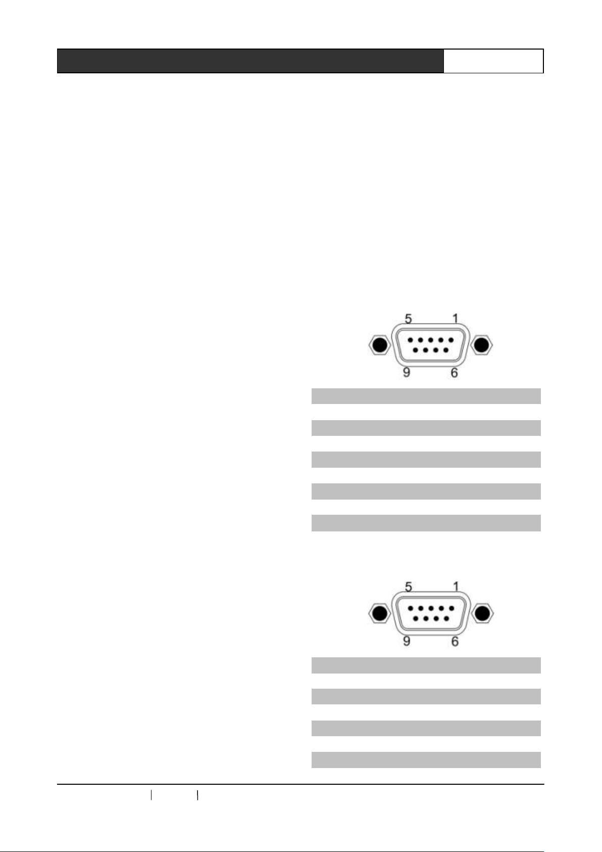
2.1.3.1 Pin instruction to CONTROL SYSTEM
COM
Pin
Signal
Instruction
1
—
—
2
—
—
3
TXD
Data transmission
4
—
—
5
GND
Signal ground
6
—
—
7
—
—
8
—
—
9
—
—
2.1.3.2 PC COM pin instruction
Pin
Signal
Instruction
1
—
—
2
TXD
Data transmission
3
RXD
Data receiving
4
—
—
5
GND
Signal ground
6
—
—

CREATOR CHINA 2010-09 WWW.CREATOR1997.COM
6
User’s Manual of Intelligent Digital Conference System
7
—
—
8
—
—
9
—
—
2.2 Conference Extended
Controller
CR-ME4000 Conference system extended
controller supports hand-in-hand serial
connection within multiple extended controllers.
2.2.1 Panel Functions Instruction
CR-ME4000 Front Panel:
CR-ME4000 Rear Panel:
1) POWER —— Power switch
2) ACTIVE ——Working indicator
3) NETWORK ——Network indicator
4 ) COMMUNICATION ——communication
indicator
5) ID ——For configuring the network ID of
ME4000.
6) DELEGATES ——3-way Discussion units
port.
7) ROUTE ——Cascade connection port. A for
connecting to preamp device and B for

CREATOR CHINA 2010-09 WWW.CREATOR1997.COM
7
User’s Manual of Intelligent Digital Conference System
connecting to amp device.
8) Connect to grounding pole
9 ) POWER INPUT——Power input, support
AC110V/220V.
2.2.2 Functions and Features
◆ Adopt 8-pin aviation plug for connection;
◆ Connect to Discussion unit along with the
AUX of conference controlling controller;
◆ Undertaken high-pressure (3500V) test;in
accordance with safety standard;
◆ The controller adopts metal shell, with 8000V
anti-static power;
◆ The controller can be installed into a 19-inch
standard cabinet.
2.3 ID Setup in Conference Unit
1、Conference ID setting is to allocate a unique
address for each conference unit (including
interpreter unit and Discussion unit) to be
identified by the controller.
2、 Conference unit is configured in the following
way: after finishing connecting the conference
system, turn on the power of conference
controller, and turn ―SET ID‖ switch to ―ON‖, and
turn on the Discussion units and interpreter units,
indicator on MIC will be on. After all conference
units are opened, turn ―SET ID‖ switch to ―OFF‖,
all MIC indicators of conference units will be off,
and the system accesses to normal status in use.
2.4 System Connection Diagram

CREATOR CHINA 2010-09 WWW.CREATOR1997.COM
8
User’s Manual of Intelligent Digital Conference System
2.5 Technical Parameters
Parameters
CR-M4101
CR-M4201
CR-ME4000
Power
Switch power 110V / 220V
Switch power 110V / 220V
Switch power 110V / 220V
Static power
consumption
10W
10W
10W
Max power
350W
350W
350W
Output power
≤110W/24V each way
≤110W/24V each way
≤110W/24V each way
Audio output
Impedance : 100Ω way :
non-balanced audio effect:
N/A
Impedance: 100Ω way :
non-balanced audio effect:
support audio effect setup
Impedance: 100Ω way :
non-balanced
MIC input
Impedance:100kΩ
LEV:-60 dB
Way:Non-balanced
Impedance:100kΩ
LEV:-60 dB
Way:Non-balanced
Impedance:100kΩ
LEV:-60 dB
Way:Non-balanced
Frequency
response
60-8kHz
60-8kHz
60-8kHz
S/N
>80dB
> 80dB
> 80dB
THD
< 0.5%
< 0.5%
< 0.5%
Carrier distortion
<1%
<1%
<1%
Cross talk
attenuation(1kHz)
>50dB
>50dB
>50dB
Weight
About 6.5KG
About 6KG
About 6KG
Dimension
483L x 275W x88H (mm)
483L x 275W x88H (mm)
483L x 275W x88H (mm)
Color
Grey
Grey
Grey

CREATOR CHINA 2010-09 WWW.CREATOR1997.COM
9
User’s Manual of Intelligent Digital Conference System
Chapter 3 DCS Discussion Unit
3.1 Type of DCS Discussion Unit
Model
Name
Shape
MIC Key
Voting
Channel
Switch
LCD
Monitor
VFD
Monitor
CR-M4104A1
Delegate
Discussion
unit
Flipping
Yes
N/A
N/A
N/A
N/A
CR-M4102A2
Chairman unit
Flipping
Yes
Yes
N/A
Yes
N/A
CR-M4104A2
Delegate unit
Flipping
Yes
Yes
N/A
N/A
N/A
CR-M4202A2
Chairman unit
Flipping
Yes
Yes
N/A
Yes
N/A
CR-M4204A2
Delegate unit
Flipping
Yes
Yes
N/A
Yes
N/A
CR-M4102B
Chairman
Discussion
unit
Desktop
Yes
N/A
N/A
N/A
N/A
CR-M4104B
Delegate
Discussion
unit
Desktop
Yes
N/A
N/A
N/A
N/A
CR-M4202B2
Chairman
Discussion
unit
Desktop
Yes
Yes
N/A
Yes
Yes
CR-M4204B2
Delegate
Discussion
unit
Desktop
Yes
Yes
N/A
Yes
Yes
CR-M4202G
Chairman
Discussion
unit
Desktop
Yes
N/A
N/A
N/A
N/A
CR-M4204G
Delegate
Discussion
unit
Desktop
Yes
N/A
N/A
N/A
N/A
CR-M4102C1
Chairman
Discussion
unit
Embedd
ed
Yes
N/A
N/A
N/A
N/A
CR-M4104C1
Delegate
Discussion
unit
Embedd
ed
Yes
N/A
N/A
N/A
N/A
CR-M4102C4
Chairman
voting unit
Embedd
ed
N/A
Yes
N/A
N/A
N/A
CR-M4104C4
Delegate
voting unit
Embedd
ed
N/A
Yes
N/A
N/A
N/A

CREATOR CHINA 2010-09 WWW.CREATOR1997.COM
10
User’s Manual of Intelligent Digital Conference System
CR-M4102D2
Chairman unit
Pulling
Yes
Yes
N/A
Yes
N/A
CR-M4104D2
Delegate unit
Pulling
Yes
Yes
N/A
Yes
N/A
CR-TP4102D
Chairman unit
Pulling
Yes
Yes
N/A
Yes
N/A
CR-M4102E
Chairman
Discussion
unit
Desktop
Yes
N/A
N/A
N/A
N/A
CR-M4104E
Delegate
Discussion
unit
Desktop
Yes
N/A
N/A
N/A
N/A
CR-M4102F
Chairman unit
Embedd
ed
Yes
Yes
N/A
Yes
N/A
CR-M4104F
Delegate unit
Embedd
ed
Yes
Yes
N/A
Yes
N/A
CR-MC4032B
Chairman
dual-audio
cabinet
N/A
N/A
N/A
N/A
N/A
CR-MC4034B
Delegate
dual-audio
cabinet
N/A
N/A
N/A
N/A
N/A
3.2 CR-M4104A1 Discussion Unit
3.2.1 Panel Functions Instruction
CR-M4104A1 Front view Side view
① MIC port
② MIC switch
③ Panel speaker
④ Headset port
⑤ Volume adjustment knob
3.2.2 Functions and Features
◆ Pure discussion flipping delegate unit;
◆ Adopts especial 8-pin high-intensity aviation
plug;
◆ Heart-shaped directional condenser pickup,
with dual-color indicator, as red for Discussion
and green for applying for Discussion;
◆ Adopt turning plugging MIC stand;
◆ With connection cable with length of 2
meters;
◆ With inside magnetic speaker, headset port
and volume adjustment knob;
◆ The units are passive devices, and with 24V
power supply from the system controller;
 Loading...