

Page 1
User
User’’ss
Manual
Manual
for
for
MAX-1301HD-B
MAX-1301HD-B
Scaler
Scaler
Switching
Switching
System
System
V1.1
V1.1
CREATOR CORPORATION(CHINA
)
Page 2
CREATOR Corporation China
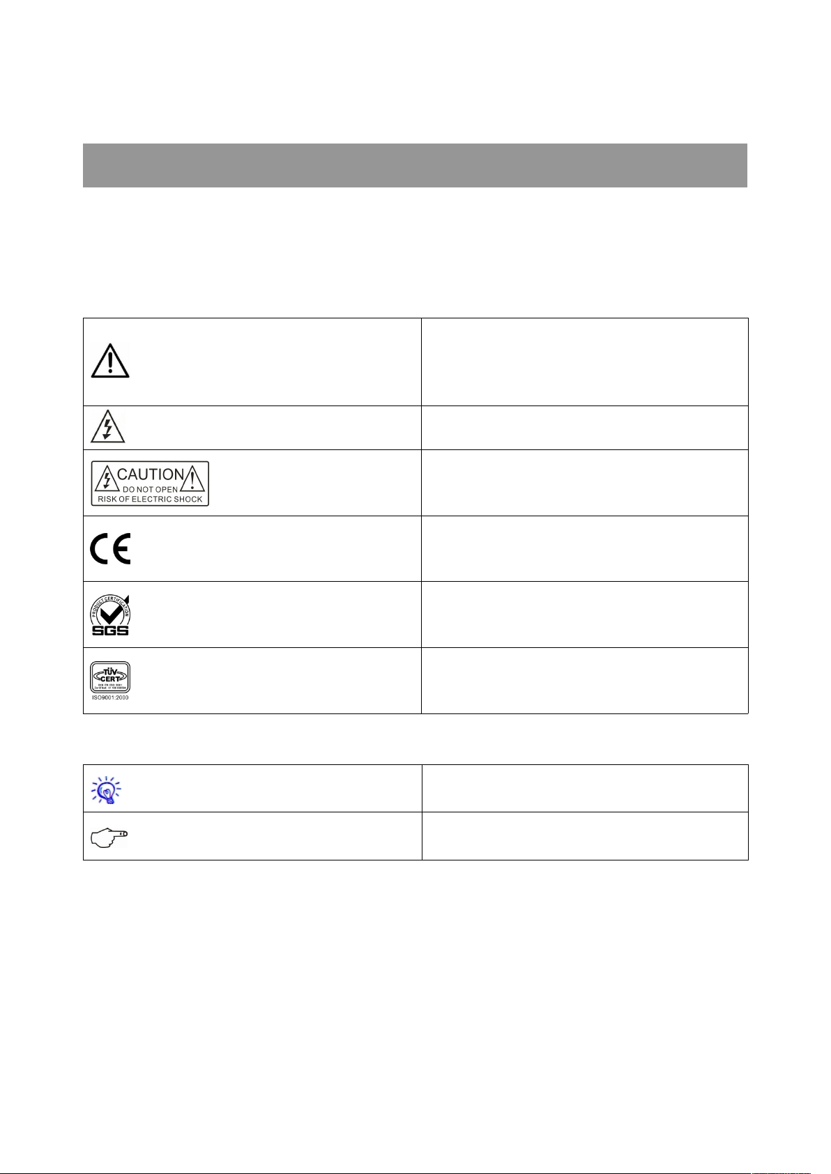
Meaning of the symbols
■ Safety Instruction
Symbols are used in the Manual and devices, referring to the possible risk to users or others , as well as the
damage to property, for helping you to safely and properly use the devices. The instruction and the implications
are as follows. Please make sure your correct understanding of these instructions before using the Manual.
To remind user to conduct according to the attached
operation and maintenance instructions. If ignore
Warning
Caution
these information, death or injury could possibly
happen.
To remind the user that the risky uninsulated voltage
in the device could caused electric shock to human.
Caution: To avoid electric shock, please don't open
the case, nor put the useless parts in it. Please
contact with qualified service staff.
CE authentication indicates the product is in line
with the EU safety regulation, and for assurance of
safety use.
SGS Authentication indicates the product has
reached the QC standard of the global-biggest Swiss
universe surveyor.
This product has acquired the ISO9001 International
Quality Authentication (Authentication authority:
Germany Rheinland TUV)
■ General Information Instruction
List the situation of causing unsuccessful operation
or setup, and relevant information needed to notice.
Lead to the page with detailed information on
relevant topic.
Page 3

Important Notices
Caution
To ensure the device in reliable use and personal
safety, please abide by the following items when in
installation, use and maintenance:
Notice in installation
◆ Please DO NOT use the product in following
places: the places with dust, oily smoke, electrical
conductive dust, corrosive gas, inflammable gas; the
places with high temperature, due, rain and wind
exposures; the places endangered by shock and
vibration. Electric shock, fire and incorrect operation
could also cause damage and deterioration to the
product.
◆ When conducting screw drilling and wiring
process, DO NOT let metal irons and wire lead drop
into the controller and air vent, which could possibly
cause fire, failure and accidental operation.
◆ After finishing the installation, it is necessary to
ensure there is no foreign matter including the
packing material like contact paper on the ventilation
surface, otherwise, it could cause poor heat
dissipation while running, as well as fire, failure and
accidental operation.
◆ Avoid conducting wiring and plugging in/out
cable socket with electricity, otherwise, electric shock,
circuit damage could easily happen.
◆ Installation and wiring should be firm and reliable.
Poor contact could cause malfunction.
◆ With regard to the application situations with
strong interference, shielded cable should be used for
the input and output of HF signal, to improve the
anti-interference performance of the system.
Note in Wiring
◆ Installation and wiring shouldn't be conducted
until external electric power is cut off, otherwise,
electric shock or device damage could happen.
◆ The product is grounded by the earth lead of the
power cable. To avoid electric shock, the earth lead is
necessary to be connected with the ground. Before
making connection with the output end or input end
of the product, please ensure it is correctly grounding.
◆ Upon finish wiring, remove the sundries. Please
cover up the terminal plate for avoiding electric
shock.
Note for Operation and Maintenance
◆ Please DO NOT touch the terminal when with
electricity, otherwise, electric shock could happen.
◆ Don't clean up and screw the terminal tight
before power is off. Such operation could cause
electric shock when with electricity.
◆ Please turn off the power before connecting or
disconnecting the communication signal cable,
peripheral modules or control units, otherwise, device
could be damaged and accidental operation could
happen.
◆ Please DO NOT disassemble the device, so as to
avoid internal electric components damage.
◆ It is necessary to read through the Manual and
fully ensure the safety, before altering the program,
trial running, starting and stopping operation.
◆ Button battery shouldn't be replaced before the
power is off. If it has to be replaced when the device
is running, it should be conducted by professional
electric technician wearing insulated gloves.
Note for declaration of the worthless.
Page 4

When declaring of worthless, please note
◆ Explosion of electrolytic capacitor on the circuit
board could happen when burning it.
◆ Please classify and dispose it. Don't dispose it into
household garbage.
◆ Please deal it as industrial waste, or in accordance
with local environmental protection regulation.
Forward
MAX-1301HD-B Scaler Switching System User’s Manual mainly introduces the operation manner, primary
parameters and trouble shootings of the host of MAX-1301HD-B.
The Manual serves as user's operation instruction only, rather than for maintenance service purpose. Since the
date of release, any function or relevant parameter alteration will be provided in supplement instruction. Please
refer to the manufacturer or dealers for inquiry.
CREATOR Electronics own the copyright of the Manual. Without permission, any unit or person shall not take
part or total of the Manual for business purpose.
The copyright of the Manual is protected by Copyright Law of People’s Republic of China and other Intellectual
Property Law. Without written permission, any copy or distribution is prohibited.
Page 5

Index
Chapter 1 General Introduction.............................................................................................................................1
1.1 Functions and Features..........................................................................................................................1
1.2 Product Dimension.................................................................................................................................. 1
Chapter 2 System Host Introduction.................................................................................................................... 2
2.1 MAX-1301HD-B Front Panel..................................................................................................................2
2.2 MAX-1301HD-B Rear Panel.................................................................................................................. 3
2.3 System Connection Diagram................................................................................................................. 4
2.4 Supplementary Introduction to Keys on Panel................................................................................... 4
2.4.1 CV Intruction................................................................................................................................4
2.4.2 COMP Instruction....................................................................................................................... 4
2.4.3 Y/C Instruction.............................................................................................................................5
2.4.4 VGA Instruction...........................................................................................................................5
2.4.5 HDMI Instruction......................................................................................................................... 5
2.5 Menu Functions Instruction....................................................................................................................6
2.5.1 VGA Channel Menu................................................................................................................... 6
2.5.2 HDMI、Video、S-video Channel Menu................................................................................. 7
Chapter 3 Remote Controller Instruction.............................................................................................................9
Chapter 4 RS-232 Control Protocol................................................................................................................... 10
Chapter 5 Performance Parameters..................................................................................................................15
Chapter 6 General Trouble Shootings............................................................................................................... 18
Page 6
Chapter 1 General Introduction
MAX-1301HD-B is a Scaler switcher incorporated
with the functions of video signal format
transforming (SCALER) and switching,
supporting a variety of video signal sources. They
are composite video signal (CV), component
video signal (Pr/Cr, Pb/Cb, Y ), S-Video (Y/C),
VGA and HDMI (High Definition Multimedia
Interface), which will all be transformed / switched
to unified VGA/HDMI/DVI signal. And the switcher
supports MIC signal input.
This product is mainly applied in broadcast
television project, multimedia conference room,
big-screen display project, TV education and
command and control center etc.
1.1 Functions and Features
◆ 12-way video signal input: 2-way CV, 2-way
S-Video, 2-way component video, 2-way VGA,
4-way HDMI/DVI. Any way of them can be
transformed / switched to unified VGA/HDMI/DVI
output.
◆ 2-way video signal output: 1-way HDMI, 1-way
VGA
◆ It supports and self-adapts to composite video
(CV) in a variety of formats including NTST, PAL,
SECAM, component video (Pr/Cr, Pb/CB, Y) and
S-Video.
◆ VIDEO(CV),COMP, S-Video and HDMI are
with separated adjustable brightness, contrast,
saturation, sharpness and hue. VGA is with
separated adjustable brightness, contrast, color
temperature and phase.
◆ It supports of switching any way of the
relevant 8-way unbalance audio input 【 5-Pin
phoenix port (each way) 】 to imbalanced audio
output.
◆ Separate control of the volume of 8-way
imbalanced audio input
◆ Support the adjustment of the bass and treble,
and balance of left and right channels.
◆ Support 1-way MIC input, which can be
inserted into main audio, and support separate
MIC.
◆ Support two modes of audio and video
separate switching to output and audio and video
combined switching to output. Audio and video
separate switching is controlled by RS232.
◆ Support power off memory function
◆ Support OSD menu
◆ After switching all input signals to
VGA/HDMI/DVI video signal output. The following
12 output resolutions are supported:
800×600 @60Hz
1024×768@60Hz
1280×720@60Hz
1280×800@60Hz
1280×1024@60Hz
1366×768@60Hz
1400×1050@60Hz
1440×900@60Hz
1600×900@60Hz
1600×1200@60Hz
1680×1050@60Hz
1920×1080@60Hz
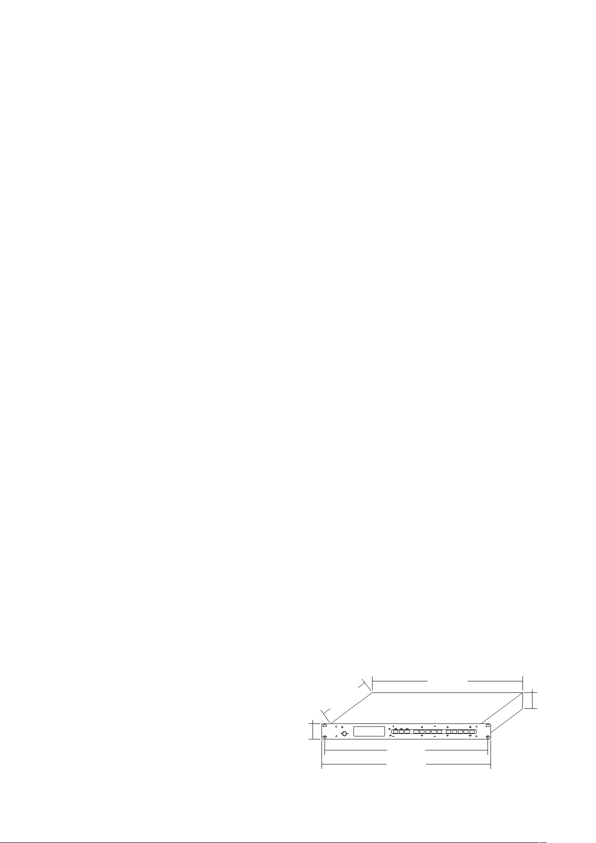
1.2 Product Dimension
42 .0 0 m m
43 .6 0 m m
23 0 .0 0 m m
43 0 .5 0 m m
4 8 2 .60 m m
46 5 .90 m m
Page 7

2
User’s Manual for MAX-1301HD-B Scaler Switching System
Chapter 2 System Host Introduction
2.1 MAX-1301HD-B Front Panel
Instruction
1 MIC Input Port
2 LCD Screen
3 SENSOR
Infrared receiving window is for the control of
infrared device, and receiving code when in
infrared learning.
4 Signal Source Selection Key --- for
choosing signal source input type, used
along with⑤
CV Signal Switching Key
For choosing CV signal, press and hold it for 1
second to access the adjustment mode of
brightness, contrast, saturation, sharpness and
chroma.
P4 2.4.1 CV Instruction
COMP Signal Switching Key
For choosing the input of VOMP signal, press and
hold it 1 second to access to the adjustment
mode of brightness, contrast, saturation,
sharpness and chroma
P4 2.4.2 COMP Instruction
Y/C Signal Switching Key
For choosing the input of Y/C signal, press and
hold it 1 second to access to the adjustment
mode of brightness, contrast, saturation,
sharpness and chroma
P 5 2.4.3 Y/C Instruction
HDMI Signal Switching Key
For choosing DVI/HDMI signal input, press and
hold for 1 second to access to adjustment mode
of brightness, contrast, saturation, sharpness and
chroma
P5 2.4.4“HDMI Instruction
VGA Signal Switching Key
For choosing VGA signal input, press and hold it
for 1 second to access to the adjustment mode of
brightness and contrast.
P5 2.4.5 VGA Instruction
The indicators on the signal source
selection keys are corresponding with the signal
CREATOR Corporation China 2010-06 WWW.CREATOR1997.COM
Page 8
3
User’s Manual for MAX-1301HD-B Scaler Switching System
channels. When signal passes through, the
corresponding indicator will be on.
5 Signal Source Switching Key
It is for choosing the input channel corresponding
to signal source (e.g. 1, 2, 3, 4), please choose
signal source before switching.
When choosing DVI/HDMI signal source input,
please slightly press the signal source switching
key (e.g. key 1, 2, 3, 4) to choose input channel of
HDMI signal source.
Press and hold the signal switching key (e.g. key
1.2.3.4) for 1 second, choose HDMI (DVI) video
signal +Y/C audio signal / VGA audio signal as
corresponding input channel (e.g. press and hold
1/2 key, choose HDMI (DVI) channel 1/2 video
signal +Y/C channel 1/2 audio signal as input
signal channel; press and hold 3/4 key, choose
HDMI (DVI) channel 3/4 audio signal + VGA
channel 1/2 audio signal as input signal channel.)
6 Display Resolution Selection Key
Press resolution switcher once to access to
resolution setup mode, press in rotation to select
the resolutions. LCD displays current operation
mode, and switches the resolution after it is
selected and held for 1 second.
In the adjustment mode of brightness, saturation,
sharpness, chroma of the signal source, this key
is also for option execution and confirmation
(Enter key)
7 MIC Volume Increase/Decrease Key
When adjusting volume, there are volume value
and bar indications in LCD display. MIC volume is
set default with intermediate value every time
turning on the device.
Press VOL-key: decrease volume
Press VOL+key: increase volume
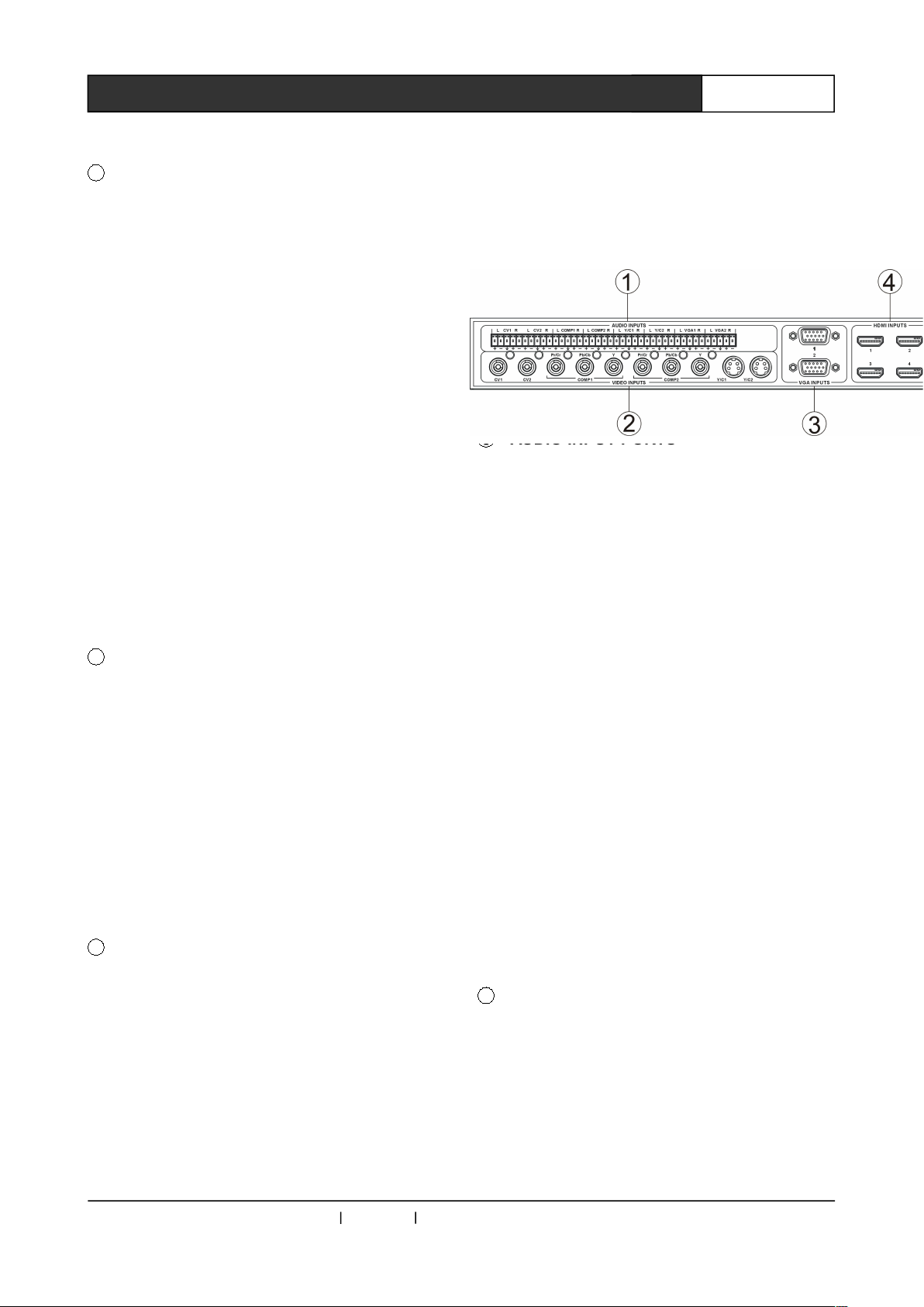
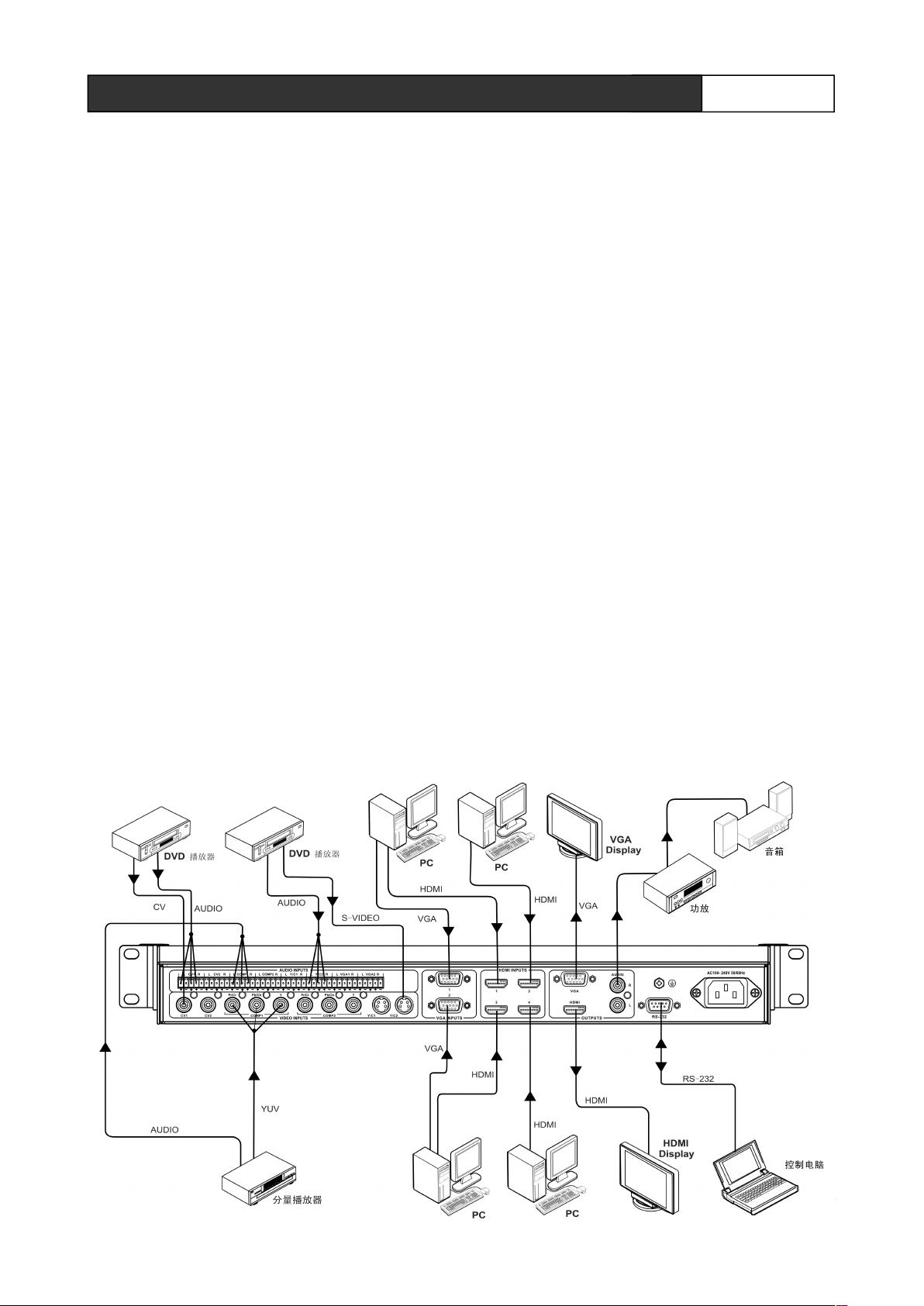
2.2 MAX-1301HD-B Rear Panel
Instruction
1 AUDIO INPUT PORTS
8-way audio input, 2-way for composite A/V input,
2-way COMP audio input, 2-way for S-view audio
input, 2-way for VGA audio input.
② VIDEO INPUT PORTS
6-way video input including 2-way composite
video signal input, 2-way COMP video signal
input, 2-way S-Video signal input.
③ VGA INPUT PORTS
Provide 2-way VGA input, for connecting to the
player or PC with VGA port.
④ HDMI INPUT PORTS
Provide 4-way HDMI inputs, for connecting to
HDMI peripheral devices like PC.
⑤ AUDIO OUTPUT PORTS
The system provides 1-way VGA output, 1-way
HDMI output, 1-way stereo output for connecting
to the peripheral devices like screen or amplifier.
8 MUTE KEY and MAIN VOLUME
INCRESE/DECREASE KEY
Mute key is effective to both MIC and main
volume.
Main VOLUME KEY
Press VOL-key: decrease volume
Press VOL+key: increase volume
CREATOR Corporation China 2010-06 WWW.CREATOR1997.COM
Page 9
4
User’s Manual for MAX-1301HD-B Scaler Switching System
⑥ RS-232 PORT
Connect to computer or other central control
devices with RS-232 port.
⑦ CONNECT TO GROUND POLE
⑧ POWER INPUT PORT
For system power input, with built-in switch
power supply, self-adapting to AC100V-240V,
50Hz/60Hz
2.3 System Connection Diagram
2.4 Supplementary Instruction to
Keys on Panel
2.4.1 CV Instruction
In CV mo de, pre ss and hol d C V ke y f or 1
sec ond to fi ne- t un e CV sy ste m
par ame ter s.
1、 function_1:1 CV brightness adjustment,used
along with parameter+ and parameter- keys.
When finishing adjustment, press Enter key to
save it in the system.
2 、 function_2:2 CV Contrast adjustment, used
along with parameter+ and parameter- keys ,
When finishing adjustment, press Enter key to
save it in the system.
3 、 function_3:3 CV Saturation adjustment ,
used along with parameter+ and parameterkeys , When finishing adjustment, press Enter
key to save it in the system.
4、 function_4:4 CV Sharpness, 锐度 调 节,与
parameter+,parameter- 键联用,调节好后,再按
Enter 键,保存到系统中。
CREATOR Corporation China 2010-06 WWW.CREATOR1997.COM
Page 10

5
User’s Manual for MAX-1301HD-B Scaler Switching System
5、function_5:5 CV Hue adjustment,used along
with parameter+ and parameter- keys , When
finishing adjustment, press Enter key to save it
in the system.
6 、 function_6:6 RESTORE CVBS DEFAULT
VALUE parameters setup, used along with
ENTER key for restoring default setup.
2.4.2 COMP Instruction
In COMP mode, press and hold COMP key for 1
second to fine-tune the system parameters of
COMP.
1、 function_1:1 COMP brightness adjustment,
used along with parameter+ and parameterkeys , When finishing adjustment, press Enter
key to save it in the system.
2 、 function_2:2 COMP Contrast adjustment ,
used along with parameter+ and parameterkeys , When finishing adjustment, press Enter
key to save it in the system.
3、 function_3:3 COMP Saturation adjustment,
used along with parameter+ and parameterkeys , When finishing adjustment, press Enter
key to save it in the system.
4、 function_4:4 COMP Sharpness adjustment,
used along with parameter+ and parameterkeys , When finishing adjustment, press Enter
key to save it in the system.
5、 function_5:5 COMP Hue adjustment ,used
along with parameter+ and parameter- keys ,
When finishing adjustment, press Enter key to
save it in the system.
6 、 function_6:6 RESTORE COMP DEFAULT
VALUE, used along with ENTER key for restoring
default setup.
2.4.3 Y/C Instruction
In Y/C mode, press and hold Y/C key for 1 second
to fine-tune Y/C system parameters.
1、 function_1:1 Y/C brightness adjustment,used
along with parameter+ and parameter- keys ,
When finishing adjustment, press Enter key to
save it in the system.
2、 function_2:2 Y/C Contrast adjustment,used
along with parameter+ and parameter- keys ,
When finishing adjustment, press Enter key to
save it in the system.
3、 function_3:3 Y/C Saturation adjustment,used
along with parameter+ and parameter- keys ,
When finishing adjustment, press Enter key to
save it in the system.
4、 function_4:4 Y/C Sharpness adjustment,used
along with parameter+ and parameter- keys ,
When finishing adjustment, press Enter key to
save it in the system.
5、 function_5:5 Y/C Hue adjustment,used along
with parameter+ and parameter- keys , When
finishing adjustment, press Enter key to save it
in the system.
6 、 function_6:6 RESTORE Y/C DEFAULT
VALUE, used along with ENTER key for restoring
default setup.
2.4.4 VGA Instruction
In VGA mode, press and hold VGA key for 1
second to fine-tune VGA parameters.
1 、 function_1:1 VGA brightness adjustment ,
used along with parameter+ and parameterkeys , When finishing adjustment, press Enter
key to save it in the system.
2、 function_2:2 VGA Contrast adjustment,used
along with parameter+ and parameter- keys ,
When finishing adjustment, press Enter key to
CREATOR Corporation China 2010-06 WWW.CREATOR1997.COM
Page 11
6
User’s Manual for MAX-1301HD-B Scaler Switching System
save it in the system.
3 、 function_3:3 RESTORE VGA DEFAULT
VALUE, used along with ENTER key for restoring
default setup.
2.4.5 HDMI Instruction
In HDMI mode, press and hold HDMI key for 1
second to fine-tune HDMI system parameters.
1、 function_1:1 HDMI brightness adjustment ,
used along with parameter+ and parameterkeys , When finishing adjustment, press Enter
key to save it in the system.
2、 function_2:2 HDMI Contrast adjustment,used
along with parameter+ and parameter- keys ,
When finishing adjustment, press Enter key to
save it in the system.
3、 function_3:3 HDMI Saturation adjustment ,
used along with parameter+ and parameterkeys , When finishing adjustment, press Enter
key to save it in the system.
4、 function_4:4 HDMI Sharpness adjustment ,
used along with parameter+ and parameterkeys , When finishing adjustment, press Enter
key to save it in the system.
5 、 function_5:5 HDMI Hue adjustment , used
along with parameter+ and parameter- keys ,
When finishing adjustment, press Enter key to
save it in the system.
6 、 function_6:6 RESTORE HDMI DEFAULT
VALUE, used along with ENTER key for restoring
default setup.
2.5 Menu Instruction
2.5.1 VGA Channel Menu
When selecting VGA signal source input, firstly
press the MENU key on the remote controller to
access to main menu with options including
PICTURE, SOUND, ADVANCE, OSD and
GEOMETRY. In menu interface, press functional
key “-” and “+” to select corresponding option,
and press functional key ENTER to access to
corresponding setup screen for adjustment. All
option can be adjustable with “-” and “+” keys.
Press MENU to return to upper level menu screen,
until exiting menu setup.
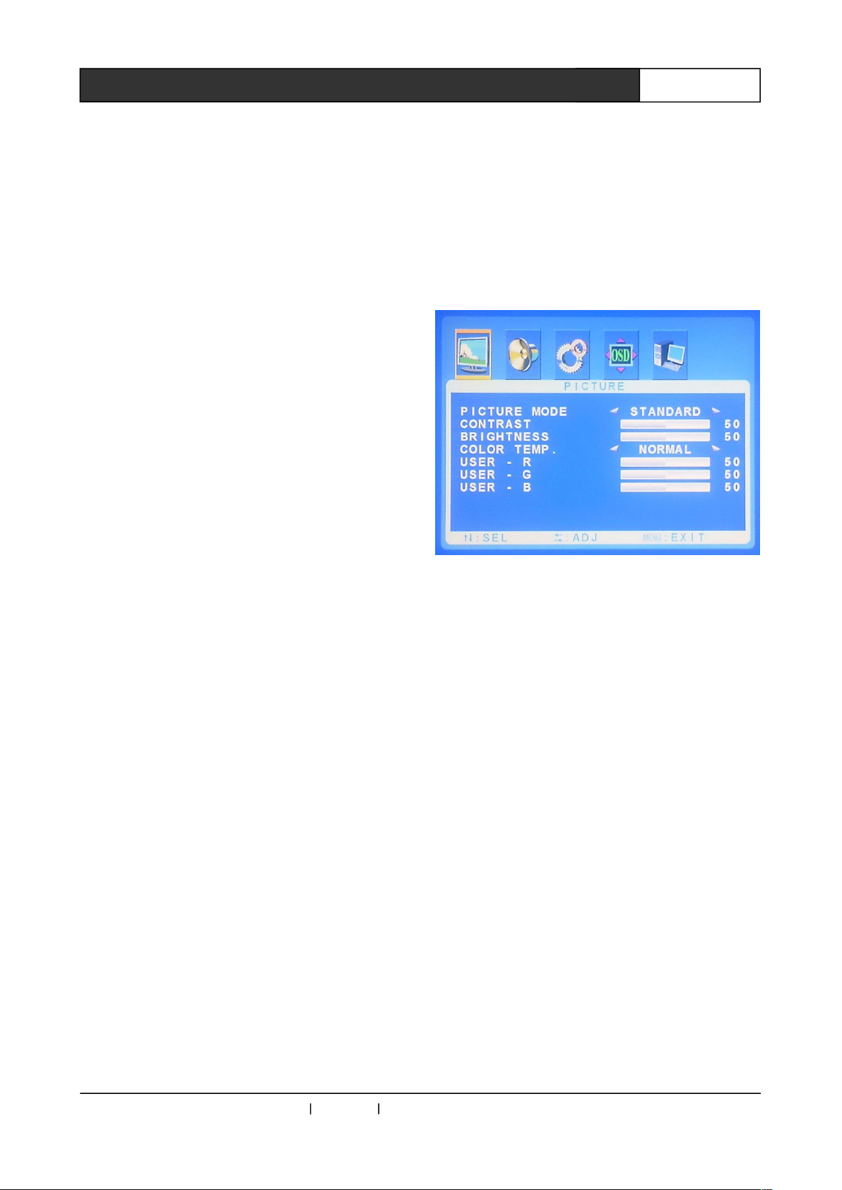
PICTURE Menu Setup Options
PICTURE MODE : Select picture display
modes including Standard, Dynamic, Sofe,
Personal.
CONTRAST:Contrast adjustment
BRIGHTNESS:Brightness adjustment
COLOR TEMP : Color temperature mode
selection including Normal, Warm, Cold and User
USER-R: When COLOR TEMP is in User
mode, configure the parameter R.
USER-G: When COLOR TEMP is in User
mode, configure the parameter G.
USER-B : When COLOR TEMP is in User
mode, configure the parameter B.
CREATOR Corporation China 2010-06 WWW.CREATOR1997.COM
Page 12
7
User’s Manual for MAX-1301HD-B Scaler Switching System
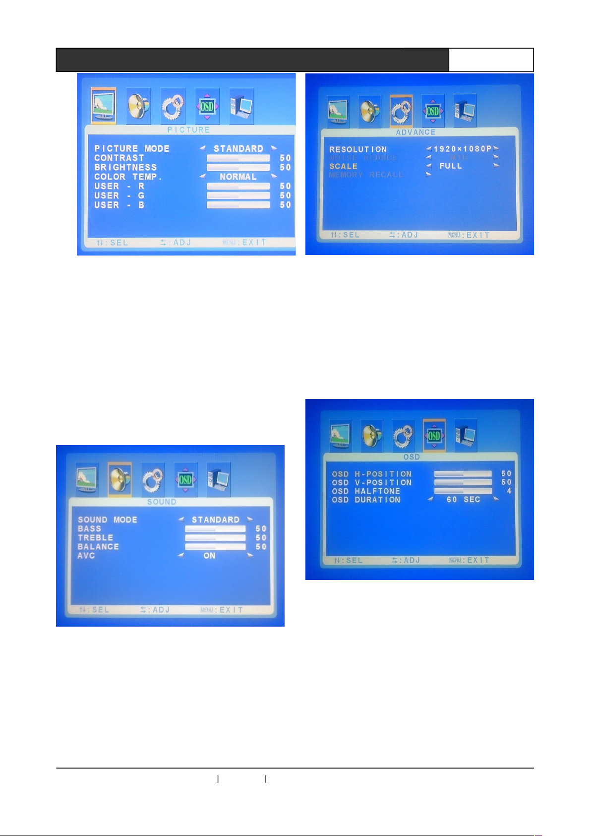
SOUND Menu Setup Option:
Select sound modes including Standard, News,
Music and Personal.
BASS:BASS parameter adjustment
TREBLE:TREBLE parameter adjustment
BALANC:BALANCE parameter adjustment
AVC:AVC ON/OFF。
ADVANCE Menu Setup Option:
RESOLUTION:Select display resolution
SCALE : Picture Zoom in/out selection
including FULL, Normal and Auto
OSD Menu Setup Option:
OSD H-POSITION:OSD horizontal position
adjustment
OSD V-POSITION : OSD vertical position
adjustment
OSD HALFTONE:OSD halftone adjustment
OSD DURATION : OSD display duration
adjustment
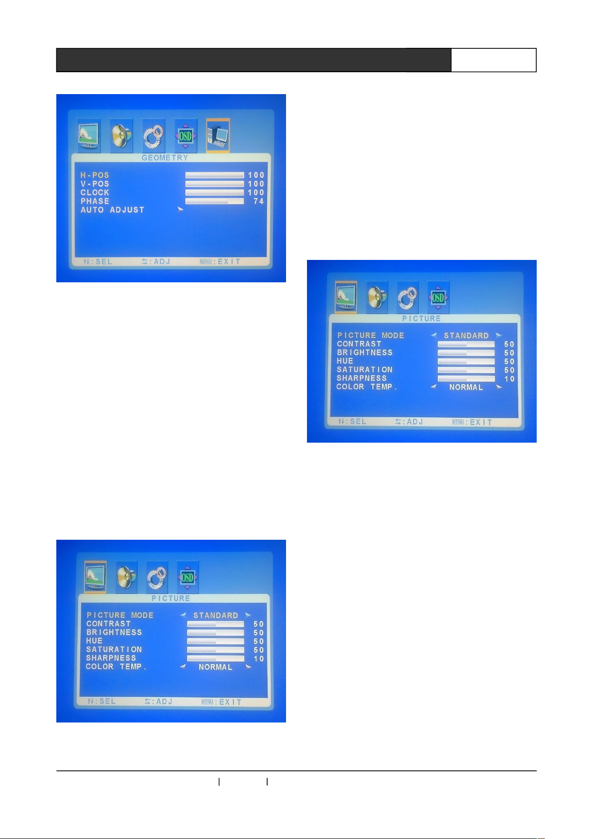
GEOMETRY Menu Setup Option:
H-POS:Manual adjust horizontal position.
V-POS:Manual adjust vertical position.
CLOCK:Manual adjust the clock.
PHASE:Manual adjust the phase.
AUTO ADJUST : Screen automatic
CREATOR Corporation China 2010-06 WWW.CREATOR1997.COM
Page 13
8
User’s Manual for MAX-1301HD-B Scaler Switching System
adjustment
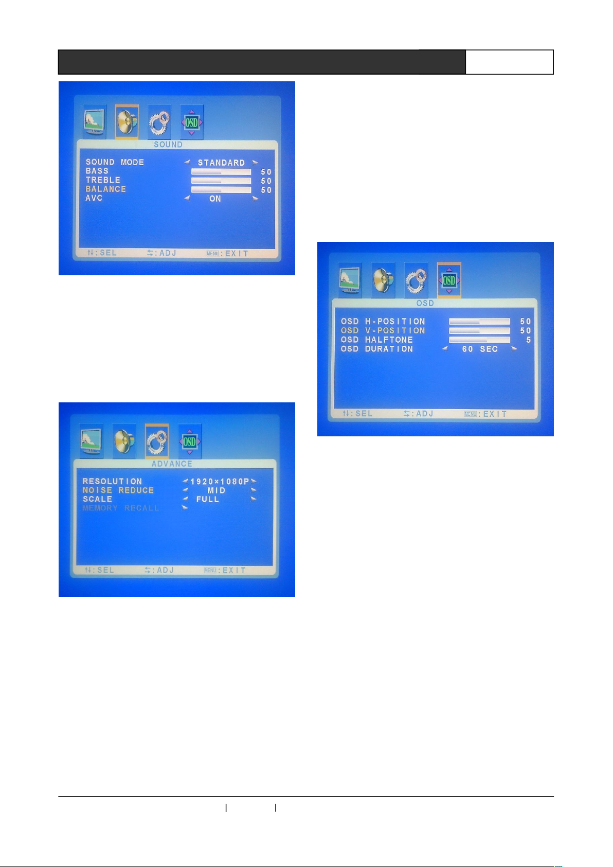
2.5.2 HDMI、Video、S-video Channel
Menu
Select the signal sources like HDMI, Video and
S-Video, firstly press the MENU key in the remote
controller to access to main menu with the
options of PICTURE, SOUND, ADVANCE and
OSD. In menu screen, press functional keys “-”
and “+” to select corresponding option, and press
the ENTER key in the menu to access to
corresponding option screen, and use “-” and “+”
keys to adjust. Press MENU return to upper level
screen, until exiting menu setup.
PICTURE Menu Setup Options:
PICTURE MODE : Including Standard,
Dynamic, Soft, Personal.
CONTRAST:Contrast adjustment
BRIGHTNESS:Brightness adjustment
HUE:Hue adjustment
SATURATION:Saturation adjustment
SHARPNESS:Sharpness adjustment
COLOR TEMP:Color temperature selection
including Normal, Warm, Cold and User.
SOUND Menu Setup Option:
SOUND MODE : Sound selection modes
including Standard, News, Music, Personal
BASS:BASS parameter adjustment
TREBLE:TREBLE parameter adjustment
BALANCE:BALANCE parameter adjustment
AVC:AVC ON/OFF。
CREATOR Corporation China 2010-06 WWW.CREATOR1997.COM
Page 14
9
User’s Manual for MAX-1301HD-B Scaler Switching System
ADVANCE Menu Setup Option:
RESOLUTION:Select display resolution
NOISE REDUCE : Select noise reduction,
including Off, Low, Mid, High, Auto.
SCALE : Screen zoom in/out selection
including the 3 modes of FULL, Normal, and Auto.
OSD Menu Setup Option
OSD H-POSITION:OSD horizontal position
adjustment
OSD V-POSITION : OSD vertical position
adjustment
OSD HALFTONE:OSD halftone adjustment
OSD DURATION : OSD display duration
adjustment
Chapter 3 Remote Controller Instruction
CREATOR Corporation China 2010-06 WWW.CREATOR1997.COM
Page 15
9
User’s Manual for MAX-1301HD-B Scaler Switching System
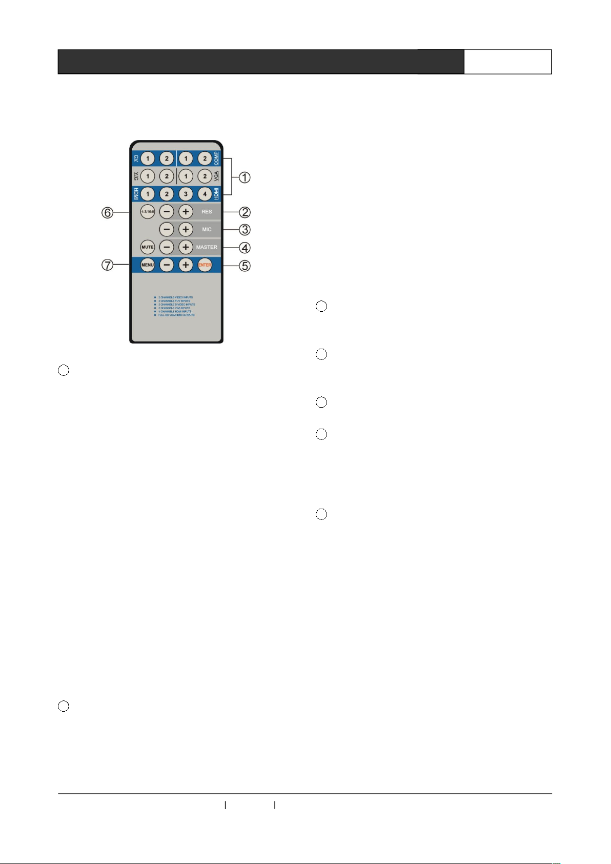
The operation and function are the same as those
of front panel. The following is the panel of remote
controller.
1 Mode and Channel Selection
Remote controller can quickly select the
corresponding channels to CV, COMP, Y/C, VGA,
DVI/HDMI modes.
When selecting HDMI signal input, slightly press
signal source switching key (e.g. key 1, 2, 3 or 4)
to select input channel for HDMI signal source.
Press and hold signal source switching key (e.g.
key 1, 2, 3 or 4) for 1 second to select HDMI (DVI)
video signal + Y/C audio/VGA audio signal as
corresponding input channel. (e.g. press and hold
1/2 key, select HDMI (DVI) channel 1/2 video
signal + Y/C channel 1/2 audio signal as channel
for signal input; Press and hold 3/4 key to select
HDMI (DVI) channel 1/2 video signal + VGA
channel 1/2 audio signal as channel for signal
input).
2 Resolution Selection Key
Press resolution selection key to select the
following resolutions in rotations.
800×600 @60Hz
1024×768@60Hz
1280×720@60Hz
1280×800@60Hz
1280×1024@60Hz
1366×768@60Hz
1400×1050@60Hz
1440×900@60Hz
1600×900@60Hz
1600×1200@60Hz
1680×1050@60Hz
1920×1080@60Hz
Note: In the mode of 800×600 @60Hz, OSD
menu cannot be displayed.
3 MIC Volume Increase/Decrease Selection
Key and Screen Zoom in/out Key.
4 Main Volume Increase/Decrease Selection
Key, MUTE Key.
5 Confirm Key
6 Screen Mode Selection Key
Press screen zoom in/out key to select within the
modes of Full, Normal and Auto, with 16:9/4:3
screen output.
7 Menu Function Selection Key
See 2.5 in Chapter 2 of the Manual for detailed
menu function instruction.
CREATOR Corporation China 2010-06 WWW.CREATOR1997.COM
Page 16
10
User’s Manual for MAX-1301HD-B Scaler Switching System
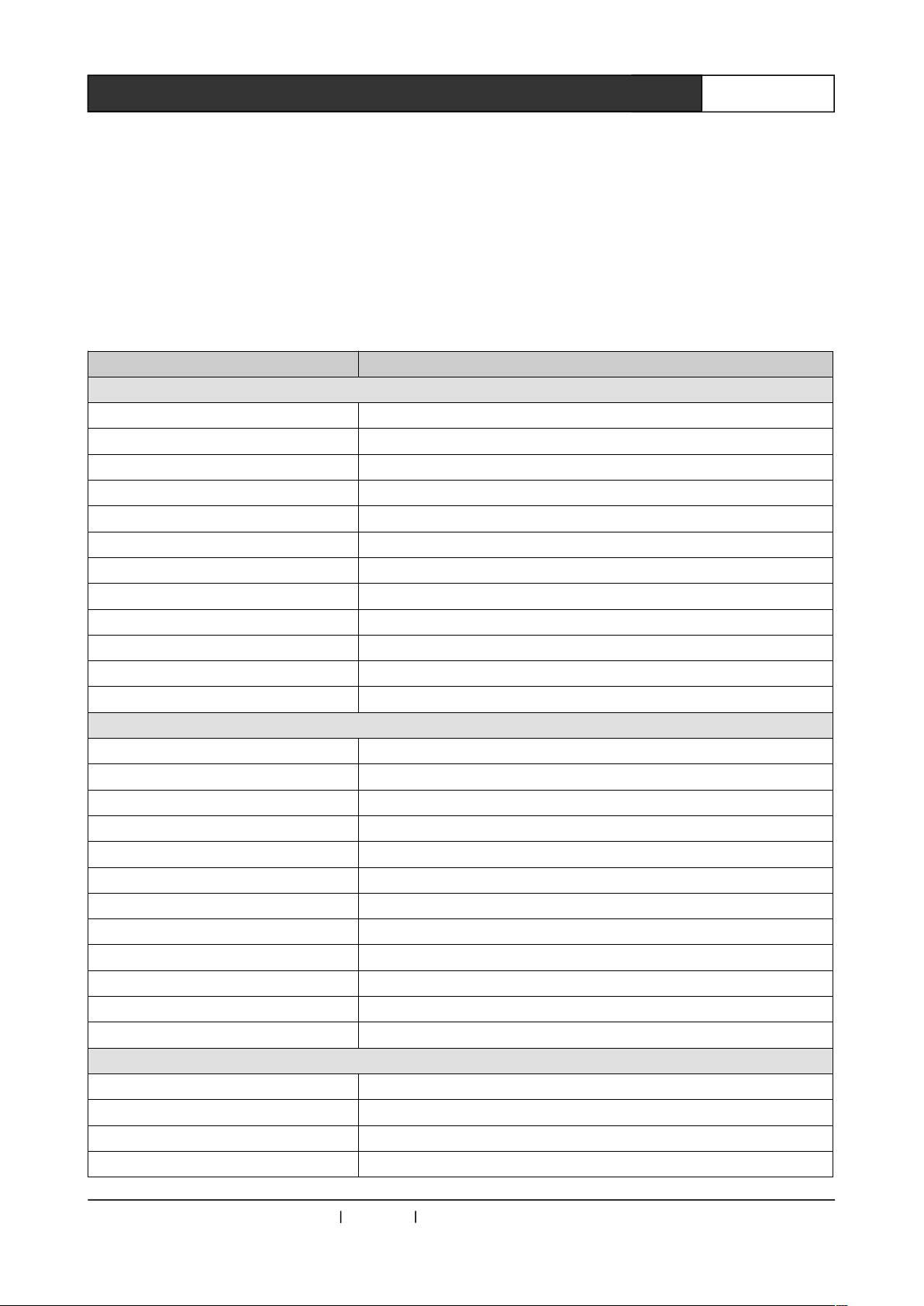
Chapter 4 RS-232 Control Protocol
Baud: 9600bps 8,n,1 format: ASCII
The System supports the third party central control device. User may take optional combinations
according to their needs. The system control codes are as follows:
Code Function
Video and Audio Switch Out:
01*01! CV1 with audio switch out
02*01! CV2 with audio switch out
03*01! COMP1 with audio switch out
04*01! COMP2 with audio switch out
05*01! Y/C1 with audio switch out
06*01! Y/C2 with audio switch out
07*01! VGA1 with audio switch out
08*01! VGA2 with audio switch out
09*01! HDMI1 with audio switch out
10*01! HDMI2 with audio switch out
11*01! HDMi3 with audio switch out
12*01! HDMI4 with audio switch out
Video Switch Out :
01*02! CV1 video switch out
02*02! CV2 video switch out
03*02! COMP1 video switch out
04*02! COMP2 video switch out
05*02! Y/C1 video switch out
06*02! Y/C2 video switch out
07*02! VGA1 video switch out
08*02! VGA2 video switch out
09*02!
10*02!
11*02! HDMI3(DVI) video switch out
12*02! HDMI4(DVI) video switch out
HDMI1(DVI) video switch out
HDMI2(DVI) video switch out
Audio Switch Out :
01*03! CV1 audio switch out
02*03! CV2 audio switch out
03*03! COMP1 audio switch out
04*03! COMP2 audio switch out
CREATOR Corporation China 2010-06 WWW.CREATOR1997.COM
Page 17
18
User’s Manual for MAX-1301HD-B Scaler Switching System
05*03! Y/C1 audio switch out
06*03! Y/C2 audio switch out
07*03! VGA1 audio switch out
08*03! VGA2 audio switch out
HDMI Sound Style :
01*04! HDMI switch out with the Sound of MIC
02*04! HDMI switch out without the Sound of MIC
HDMI Output Mode:
01*05! HDMI Output is DVI mode
02*05! HDMI Output is HDMI mode
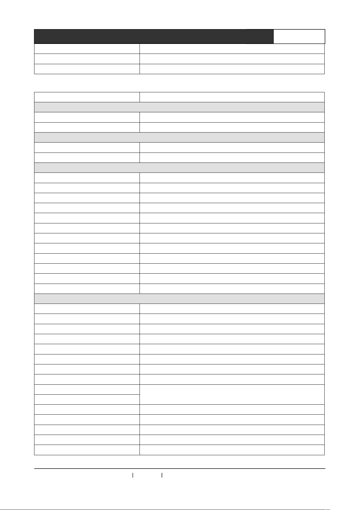
General Command :
xx$47! Set MIC volume;(0< xx <100)
xx$48! Set Master volume;(0< xx <100)
01$01! MIC volume level up
02$01! MIC volume level down
03$01! Master volume level up
04$01! Master volume level down
05$01! Mute on
06$01! Mute off
07$01! Menu
08$01! Menu Left
09$01! Menu Right
10$01! Menu Enter
Video Output Command :
01$02! 800*600(SVGA) at 60 Hz
02$02! 1024 x 768 (XGA) at 60 Hz (default)
03$02! 1280 x 720 (HDTV 720p) at 60 Hz
04$02! 1280 x 800 at 60 Hz
05$02! 1280 x 1024 (SXGA) at 60 Hz
06$02! 1366 x 768 (HDTV 768p) at 60 Hz
07$02! 1400 x 1050 at 60 Hz
08$02! 1440 x 900 at 60 Hz
09$02! 1600 x 900 at 60 Hz
10$02! 1600 x 1200 (UXGA) at 60 Hz
11$02! 1680 x 1050 at 60 Hz
12$02! 1920 x 1080 (HDTV 1080p) at 60 Hz
13$02!
14$02!
15$02! Noise Reduce:Mid
Noise Reduce:Off
Noise Reduce:Low
CREATOR Corporation China 2010-06 WWW.CREATOR1997.COM
Page 18
18
User’s Manual for MAX-1301HD-B Scaler Switching System
16$02! Noise Reduce:High
17$02! Noise Reduce:Auto
18$02! Scale Full 16:9
19$02! Scale Normal 4:3
20$02! Scale Auto
OSD Command :
01$03! OSD Duration 5s
02$03! OSD Duration 15s
03$03! OSD Duration 30s
04$03! OSD Duration 60s
xx$04! select the OSD h-position, 00--99% (0< xx <100)
xx$05! select the OSD v-position, 00--99% (0< xx <100)
xx$06! select the OSD halftone, 0--8 (0< xx <=8)
Sound Command :
01$07! Sound Mode:Standard
02$07! Sound Mode:News
03$07!
04$07!
05$07! Sound AVC off
06$07 Sound AVC on
xx$08! select the Sound BASS, 00--99% (0< xx <100)
xx$09! select the Sound TREBLE, 00--99% (0< xx <100)
xx$10! select the Sound BALANCE, 00--99% (0< xx <100)
CV Channel Command :
01$11!
02$11!
03$11! CV Picture Mode:Soft
04$11! CV Picture Mode:Personal
05$11!
06$11!
07$11! CV Color Temp:Cold
08$11! restore the CV Brightness… to the default value
xx$12! select the CV brightness, 00--99% (0< xx <100)
xx$13! select the CV contrast, 00--99% (0< xx <100)
xx$14! select the CV saturation, 00--99% (0< xx <100)
xx$15! select the CV sharpness, 00--20 (0< xx <=20)
xx$16! select the CV hue, 00--99% (0< xx <100)
COMP Channel Command :
01$17! COMP Picture Mode:Standard
02$17! COMP Picture Mode:Dynamic
Sound Mode:Music
Sound Mode:Personal
CV Picture Mode:Standard
CV Picture Mode:Dynamic
CV Color Temp:Normal
CV Color Temp:Warm
CREATOR Corporation China 2010-06 WWW.CREATOR1997.COM
Page 19
18
User’s Manual for MAX-1301HD-B Scaler Switching System
03$17! COMP Picture Mode:Sofe
04$17! COMP Picture Mode:Personal
05$17!
06$17! COMP Color Temp:Warm
07$17! COMP Color Temp:Cold
08$17! restore the COMP Brightness… to the default value
xx$18! select the COMP brightness, 00--99% (0< xx <100)
xx$19! select the COMP contrast, 00--99% (0< xx <100)
xx$20! select the COMP saturation, 00--99% (0< xx <100)
xx$21! select the COMP sharpness, 00--20 (0< xx <=20)
xx$22! select the COMP hue, 00--99% (0< xx <100)
Y/C Channle Command :
01$23! Y/C Picture Mode:Standard
02$23! Y/C Picture Mode:Dynamic
03$23!
04$23!
05$23! Y/C Color Temp:Normal
06$23! Y/C Color Temp:Warm
07$23!
08$23! restore the Y/C Brightness… to the default value
xx$24! select the Y/C brightness, 00--99% (0< xx <100)
xx$25! select the Y/C contrast, 00--99% (0< xx <100)
xx$26! select the Y/C saturation, 00--99% (0< xx <100)
xx$27! select the Y/C sharpness, 00--20 (0< xx <=20)
xx$28! select the Y/C hue, 00--99% (0< xx <100)
VGA Channle Command :
01$29!
02$29!
03$29! VGA Picture Mode:Soft
04$29! VGA Picture Mode:Personal
05$29!
06$29!
07$29! VGA Color Temp:Cold
08$29! VGA Color Temp:User
xx$30! select the VGA Color temp user-R, 00--99% (0< xx <100)
xx$31! select the VGA Color temp user-G, 00--99% (0< xx <100)
xx$32! select the VGA Color temp user-B, 00--99% (0< xx <100)
09$29! select VGA Auto Adjust
xx$33! select the VGA H-Position, 00--99% (0< xx <100)
xx$34! select the VGA V-Position, 00--99% (0< xx <100)
COMP Color Temp:Normal
Y/C Picture Mode:Soft
Y/C Picture Mode:Personal
Y/C Color Temp:Cold
VGA Picture Mode:Standard
VGA Picture Mode:Dynamic
VGA Color Temp:Normal
VGA Color Temp:Warm
CREATOR Corporation China 2010-06 WWW.CREATOR1997.COM
Page 20
18
User’s Manual for MAX-1301HD-B Scaler Switching System
xx$35! select the VGA Clock, 00--99% (0< xx <100)
xx$36! select the VGA Phase, 00--99% (0< xx <100)
10$29! restore the VGA Brightness… to the default value
xx$37! select the VGA brightness, 00--99% (0< xx <100)
xx$38! select the VGA contrast, 00--99% (0< xx <100)
HDMI Channle Command :
01$39!
02$39!
03$39! HDMI Picture Mode:Sofe
04$39! HDMI Picture Mode:Personal
05$39!
06$39!
07$39! HDMI Color Temp:Cold
08$39! restore the HDMI Brightness… to the default value
xx$40! select the HDMI brightness, 00--99% (0< xx <100)
xx$41! select the HDMI contrast, 00--99% (0< xx <100)
xx$42! select the HDMI saturation, 00--99% (0< xx <100)
xx$43! select the HDMI sharpness, 00--20 (0< xx <=20)
xx$44! select the HDMI hue, 00--99% (0< xx <100)
LCD light time command:
xx$45! select LCD light time.( (0< xx <=60))
EDID command:
01$46! Read EDID from HDMI sink device.
Background setting:
01$49! Select black Backgrounds.
02$49!
Display channel information:
01$50!
Special Command :
HDMI Picture Mode:Standard
HDMI Picture Mode:Dynamic
HDMI Color Temp:Normal
HDMI Color Temp:Warm
Select blue Background.
Display information on screen. and Auto exit after 3s.
01#01! read present state
02#01! read present Firmware Ver.
03#01! read system information
04#01! Reset to factory value.
CREATOR Corporation China 2010-06 WWW.CREATOR1997.COM
Page 21
18
User’s Manual for MAX-1301HD-B Scaler Switching System
Chapter 5 Performance Parameters
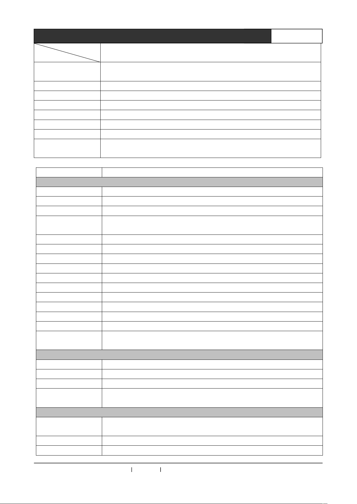
VGA,S-video, COMP Component Video(YPbPr/YCbCr),Composite Video(CVBS),
HDMI/DVI。
Model
Tech. Spec.
Video
Gain 0 dB
Bandwidth AV :150MHz, S-Video:150MHz, VGA:375 MHz,HDMI/DVI:2.25Gbps。
Input Multi-channel vs.
single channel crosstalk
Differential Phase I/OS <1.28°,3.58 MHz
Differential Phase Error 0.1°, 3.58-4.43 MHz
Differential Gain Error
Time
Switching Speed 100 ns (Longest Time)
Signal Type
Video Input CV S-Video VGA COMP HDMI/DVI
Interface
Signal Strength
Min/Max Level Analogue Signal: -2V/+2V
Impedance 75 Ω
Return Loss <-30dB@5MHz
Horizontal Frequency
Response
Vertical Frequency
Response
VGA Video Output
Interface 15-pin HD Female Connector
Min/Max Level -2.0V / +2.0V
Impedance 75 Ω
Return Loss <-40dB@5MHz
DC Offset Max ±5mV
VGA Sync Signal
-50dB @50 MHz, -45dB @10 MHz
0.1%, 3.58-4.43 MHz
RCA
Female
Connector
1V p-p : Y Component Video, S-Video,Composite Video;
0.7V p-p: VGA(Computer Signal);
0.3V p-p: Component Video、 S-Video 的 C ,HDMI/DVI video
30-200KHZ
20Hz-240Hz
S-Video
Terminal(Y-C
Terminal)
MAX1301HD
15-pin HD
Female
Connector
RCA
Female
Connector
HDMI Terminal
CREATOR Corporation China 2010-06 WWW.CREATOR1997.COM
Page 22
38
User’s Manual for MAX-1301HD-B Scaler Switching System
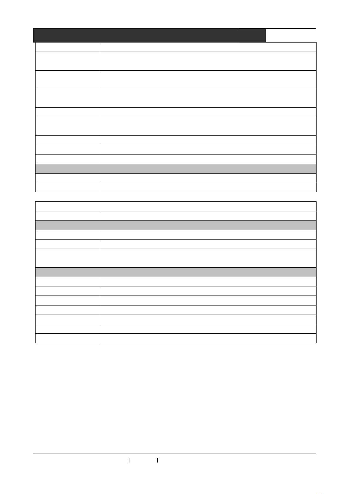
Model
4-way 10pin Phoenix Connector / each way is with imbalanced audio input. 1-way 2RCA
connector imbalanced input.
Tech. Spec.
Input / Output Signal
Type
Video System
Input Level 0.5V- 5.0V p-p,: 4.0V p-p Normal
Output Level AGC-TTL: 5Vp-p, unterminated
Input Impedance 510 Ω
Output Impedance 75 Ω
Max Transfer Delay Horizontal :90ns Vertical:160ns
Max Ascend/Descend
Time
RGBHV, RGBS, RGsB, RsGsBs, Composite Video, Component Video
NTSC 3.58,NTSC 4.43,PAL,SECAM
4ns
MAX1301HD
Polar
HDMI Video Input
Protocol Supported HDMI1.3a, DVI1.0, HDCP1.3, x.v.Color, TrueHD, DTS-HD
PIXEL Bandwidth 165MHz, Full Digital
Interface Bandwidth 2.25Gbps
Max Resolution
Clock Jitter <0.15 Tbit
Rise time <0.3Tbit (20%--80%)
Fall time <0.3Tbit (20%--80%)
Signal Type HDMI / DVI-D full digital T.M.D.S. signal in HDMI 1.3a / DVI 1.0 Specification
Interface HDMI-A Interface (Type A connector )
Signal Strength T.M.D.S. +/- 0.4Vpp
Min/Max Level T.M.D.S. 2.9V/3.3V
Impedance 50 Ω
Input EDID Use System Default EDID,( Support Terminal EDID mapping to input terminal)
Max. DC Bias Error 15mV
Max Input Distance
Recommended
HDMI Video Output
Interface HDMI-A Interface(Type A connector )
Min/Max Level T.M.D.S. 2.9V/3.3V
Impedance 50 Ω
Max Input Distance
Recommended
Audio Signal
Input/output Interface
Positive or Negative(Fully the same as input)
HDPC 1600x1200@60_24bit Color Depth
HDTV 1920x1080P@60_24bit Color Depth
Less than 25m, at 1920x1080p@60 (Recommended to use special HDMI wire with
authentication, like Molex TM)
Less than 10m, at 1920x1080p@60 (Recommended to use special HDMI wire with
authentication, like Molex TM)
Gain 0 dB
Frequency Response 20 Hz ~ 20 kHz,
CREATOR Corporation China 2010-06 WWW.CREATOR1997.COM
Page 23
17
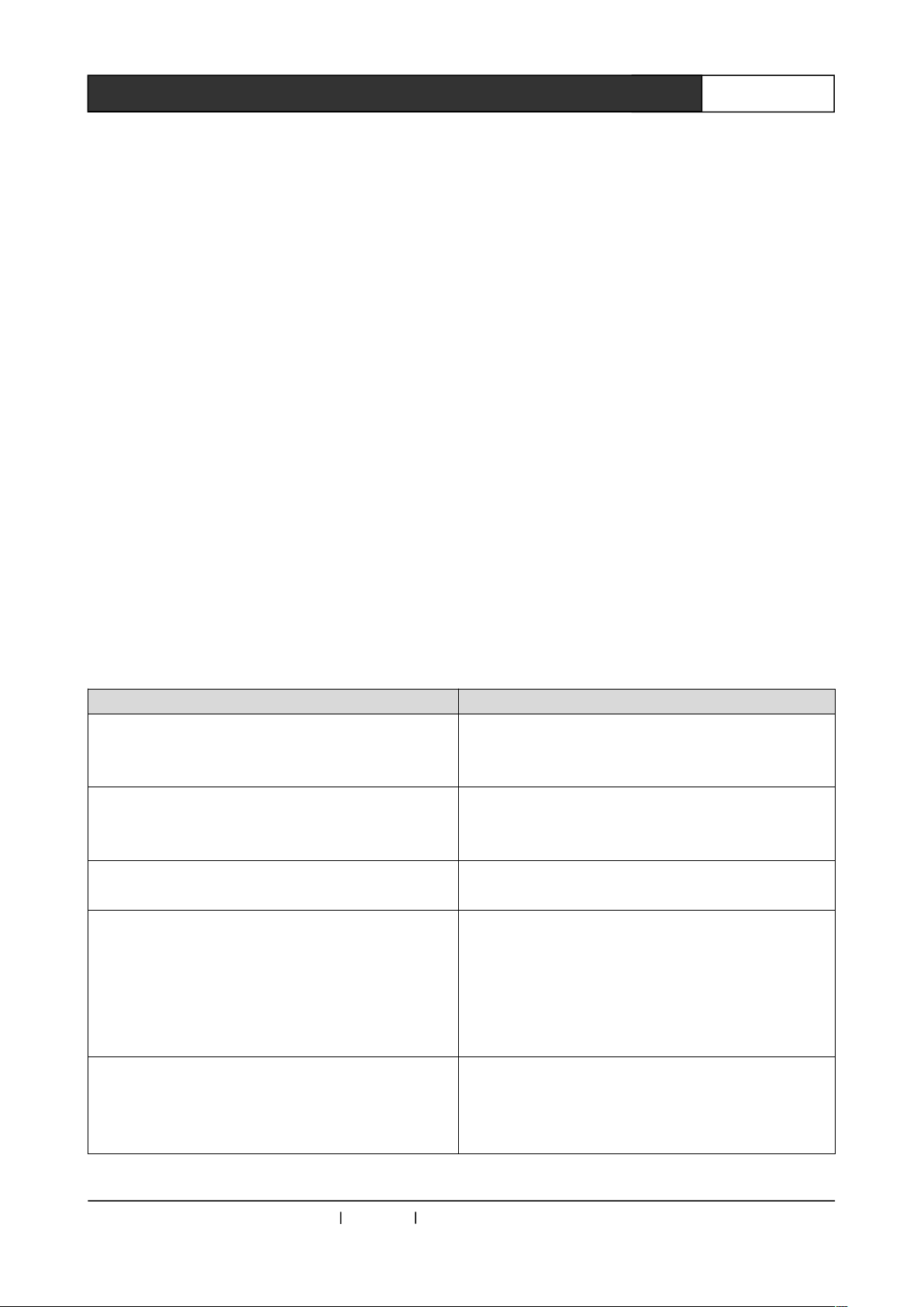
User’s Manual for MAX-1301HD-B Scaler Switching System
THD + Noise 0.05% @ 1 kHz (Rated Voltage)
Signal to Noise Ratio
(S/N )
Common-Mode
Rejection Ratio(CMRR)
>58dB
Stereo Channel
Crosstalk
Signal Type Stereo (Imbalanced Connecting Audio)
Impedance
Max Input Level +19.5dBu, (Balanced or Imbalanced Connection)
Gain Error ±0.1dB @20 Hz ~ 20 kHz
Max Output Level
MIC
MIC Type Moving-coil Response
Input Sensitivity 25mV
Band Response 50Hz-16K Hz
Interface Type Mono Input
Control Type
Serial Control Interface RS-232, 9-pin Female D type interface
Baud Rate and Protocol Baud Rate:9600, Data Bit, Stop Bit:1, No Parity Bit
Structure of Serial
Control Interface
Specification
Power
Temp
Humidity
Case Dimension 483(L)X230(W)X44mm(H)
Weight 1.9kg
Average Failure Interval 30,000 Hours
Warranty 1 year free repair, and life-time maintenance
>80dB @ 1 kHz
>75dB @: 20 Hz ~ 20 kHz
Input:>10 kΩ(Balanced or Imbalanced Connection)
Output:50 Ω (Imbalanced Connection), 100 Ω( Balanced Connection)
+19.5dBu, (Balanced or Imbalanced Connection)
2 = TX, 3 = RX, 5 = GND
100VAC-240VAC~50/60 Hz, International Self-adapted Power
Storage and in use: -20°~ +70°C
Storage and in use: 10% ~90%
CREATOR Corporation China 2010-06 WWW.CREATOR1997.COM
Page 24
18
User’s Manual for MAX-1301HD-B Scaler Switching System
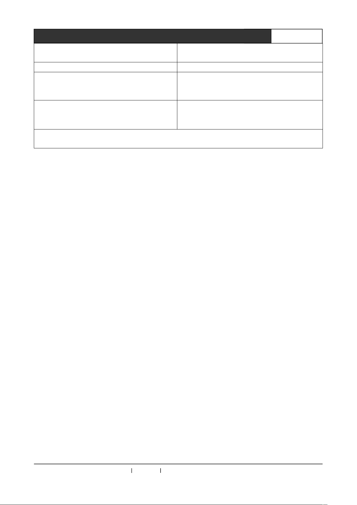
Chapter 6 General Trouble Shootings
When the peripheral device connected to MAX1301HD
has ghost image. E.g. Projector has ghost image or
unclear picture.
Possibly the VGA signal wire doesn’t have the terminals at
both end correspondingly connected or there is broken
circuit (short circuit) in the wire.
● Check the communication port configured by control
software to see whether it is corresponding with the serial
port of the device connected.
● Check to see whether the communication port of the
computer is in good condition, whether it is using correct
communication protocol.
Please check to see whether there is signal at the input
terminal (May use oscilloscope or multi-meter). If no signal
input, possibly the input wire is broken or the connector is
loose. Please replace the wire.
Trouble Solution
Color lost or without video signal output
Possibly the projector is not correctly fine-tuned or using
unqualified wire. Please adjust corresponding keys of the
projector, or replace the wire.
Remote controller cannot control MAX 1301HD Scaler
Serial port (generally referring to computer port) cannot
control MAX1301HD Scaler.
When MAX1301HD is switching, there is return code, but
without corresponding image output.
CREATOR Corporation China 2010-06 WWW.CREATOR1997.COM
● Possibly the battery is running out, please replace it.
● Possibly the controller is out of order, please repair it.
Page 25
38
User’s Manual for MAX-1301HD-B Scaler Switching System
If POWER indicator is off and without LCD display, no
Possibly there is broken connection wire, please replace it.
If the panel keys, communication and remote controller of MAX1301HD Scaler are all out of control, possibly the host
has internal damage, please ask professional technician for maintenance.
response for operation
Output image is interfered Possibly the input or output device is not well-grounded.
When plugging A/V port, feel obvious static electricity.
LCD display is normal, and there is return code from
communication port, but without image or audio output.
Check to see whether the input power is in good contact.
Maybe the ground wire of the device is not well-grounded.
Please use correct way to ground to floor, otherwise, the
host would be easily damaged and have shorter lifetime.
Possibly the A/V port is loose, please replace it.
Possibly the wire is short-circuited, please replace it.
CREATOR Corporation China 2010-06 WWW.CREATOR1997.COM
Page 26

CREATOR CORPORATION(CHINA)
Copyright by CREATOR
Last Revision:06/2010
 Loading...