


Operator’s Manual
®
6.5 Horse Power
POWER PROPELLED YARD VACUUM
Model No. 247.770990
CAUTION: Before using this product, read this manual and follow all safety rules and operating instructions.
SAFETY
ASSEMBLY
•OPERATION
•MAINTENANCE
•PARTS LIST
•ESPAÑOL
Sears, Roebuck and Co., Hoffman Estates, IL 60179, U.S.A.
Visit our web site: www.sears.com/craftsman
FORM NO. 769-01281B 06/27/2006

TABLE OF CONTENTS
Warranty Statement.................................. |
Page 2 |
Off-Season Storage.................................. |
Page 20 |
Repair Protection Agreement.................... |
Page 3 |
Trouble Shooting....................................... |
Page 21 |
Safe Operation Practices.......................... |
Pages 4-5 |
Parts List................................................... |
Page 22-30 |
Assembly................................................... |
Pages 6-9 |
Safety Labels............................................. |
Page 31 |
Operation................................................... |
Pages 10-13 |
Español...................................................... |
Page 33 |
Maintenance.............................................. |
Pages 14-15 |
Service Numbers....................................... |
Back Cover |
Service And Adjustment........................... |
Page 16-19 |
|
|
WARRANTY
One Year Full Warranty on Craftsman Yard Vacuum
This equipment is covered by a one-year warranty, provided that it is maintained, lubricated, and tuned up according to the instructions in the operator’s manual. During the warranty year, if this equipment experiences any failure due to defects in material or workmanship, RETURN IT TO YOUR NEAREST SEARS PARTS & REPAIR CENTER, and Sears will repair it, free of charge. In-home warranty service is available, but you will have to pay a trip charge.
This warranty does not cover:
•Expendable items which become worn during normal use, such as spark plugs, air cleaners, belts, and oil filters.
•Tire replacement or repair caused by punctures from outside objects, such as nails, thorns, stumps, or glass.
•Repairs necessary because of operator abuse, including but not limited to, damage caused by objects, such as stones, metal debris or oversized pieces of wood, or impacting objects that bend the frame or crankshaft, or over-speeding the engine.
•Repairs necessary because of operator negligence, including but not limited to, electrical and mechanical damage caused by improper storage, failure to use the proper grade and amount of engine oil, or failure to maintain the equipment according to the instructions contained in the operator’s manual.
•Engine (fuel system) cleaning or repairs caused by fuel determined to be contaminated or oxidized (stale). In general, fuel should be used within 30 days of its purchase date.
•Equipment if used for commercial or rental purposes.
TO LOCATE THE NEAREST SEARS PARTS & REPAIR CENTER OR TO SCHEDULE SERVICE, SIMPLY CONTACT SEARS AT 1-800-4-MY- HOME®.
This warranty gives you specific legal rights and you may also have other rights which may vary from state to state.
SEARS, ROEBUCK AND CO., D/817WA, HOFFMAN ESTATES, IL 60179
PRODUCT SPECIFICATIONS
Horse Power: |
6.5 |
Engine Oil Type: |
SAE 30 |
Engine Oil Capacity: |
18 ounces |
Fuel Capacity: |
1 1/2 Quarts |
Spark Plug: |
Champion® RJ19LM |
Spark Plug Gap: |
.030” |
|
|
MODEL NUMBER
Model Number..............................................................
Serial Number...............................................................
Date of Purchase..........................................................
Record the model number, serial number
and date of purchase above

REPAIR PROTECTION AGREEMENT
Congratulations on making a smart purchase. Your new Craftsman® product is designed and manufactured for years of dependable operation. But like all products, it may require repair from time to time. That’s when having a Repair Protection Agreement can save you money and aggravation.
Here’s what’s included in the Agreement:
•Expert service by our 12,000 professional repair specialists
•Unlimited service and no charge for parts and labor on all covered repairs
•Product replacement if your covered product can’t be fixed
•Discount of 10% from regular price of service and service-related parts not covered by the agreement; also, 10% off regular price of preventive maintenance check
•Fast help by phone – phone support from a Sears technician on products requiring in-home repair, plus convenient repair scheduling
Purchase a Repair Protection Agreement now and protect yourself from unexpected hassle and expense.
Once you purchase the Agreement, a simple phone call is all that it takes for you to schedule service. You can call anytime day or night, or schedule a service appointment online.
Sears has over 12,000 professional repair specialists, who have access to over 4.5 million quality parts and accessories. That’s the kind of professionalism you can count on to help prolong the life of your new purchase for years to come. Purchase your Repair Protection Agreement today!
Some limitations and exclusions apply. For prices and additional information call 1-800-827-6655.
Sears Installation Service
For Sears professional installation of home appliances, garage door openers, water heaters, and other major home items, in the U.S.A. call 1-800-4-MY-HOME®

SAFE OPERATION PRACTICES
WARNING: Engine Exhaust, some of its constituents, and certain vehicle components contain or emit chemicals known to State of California to cause cancer and birth defects or other reproductive harm.
DANGER: This machine was built to be operated according to the rules for safe operation in this manual. As with any type of power equipment, carelessness or error on the part of the operator can result in serious injury. This machine is capable of amputating hands and feet and throwing objects. Failure to observe the following safety instructions could result in serious injury or death.
WARNING: This symbol points out important safety instructions which, if not followed, could endanger the personal safety and/or property of yourself and others. Read and follow all instructions in this manual before attempting to operate this machine. Failure to comply with these instructions may result in personal injury.
When you see this symbol. HEED ITS WARNING!
Training
1.Read, understand, and follow all instructions on the machine and in the manual(s) before attempting to assemble and operate. Keep this manual in a safe place for future and regular reference and for ordering replacement parts.
2.Be familiar with all controls and their proper operation. Know how to stop the machine and disengage them quickly.
3.Never allow children under 16 years old to operate this machine. Children 16 years old and over should read and understand the operation instructions and safety rules in this manual and should be trained and supervised by a parent.
4.Never allow adults to operate this machine without proper instruction.
5.Keep bystanders, helpers, pets, and children at least 75 feet from the machine while it is in operation. Stop machine if anyone enters the area.
6.Never run an engine indoors or in a poorly ventilated area. Engine exhaust contains carbon monoxide, an odorless and deadly gas.
7.Do not put hands and feet near rotating parts or in the feeding chambers and discharge opening. Contact with the rotating impeller can amputate fingers, hands, and feet.
8.Never attempt to unclog either the feed intake or discharge opening, remove or empty vacuum bag, or inspect and repair the machine while the engine is running. Shut the engine off and wait until all moving parts have come to a complete stop. Disconnect the spark plug wire and ground it against the engine.
Preparation
1.Thoroughly inspect the area where the equipment is to be used. Remove all rocks, bottles, cans, or other foreign objects which could be picked up or thrown and cause personal injury or damage to the machine.
2.Always wear safety glasses or safety goggles during operation or while performing an adjustment or repair, to protect eyes. Thrown objects which ricochet can cause serious injury to the eyes.
3.Wear sturdy, rough-soled work shoes and close-fitting slacks and shirts. Loose fitting clothes or jewelry can be caught in movable parts. Never operate this machine in bare feet or sandals. Wear leather work gloves when feeding material in the chipper chute.
4.Before starting, check all bolts and screws for proper tightness to be sure the machine is in safe working condition. Also, visually inspect machine for any damage at frequent intervals.
5.Maintain or replace safety and instructions labels, as necessary.
6.To avoid personal injury or property damage use extreme care in handling gasoline. Gasoline is extremely flammable and the vapors are explosive. Serious personal injury can occur when gasoline is spilled on yourself
or your clothes which can ignite. Wash your skin and change clothes immediately.
a.Use only an approved gasoline container.
b.Extinguish all cigarettes, cigars, pipes, and other sources of ignition.
c.Never fuel machine indoors.
d.Never remove gas cap or add fuel while the engine is hot or running.
e.Allow engine to cool at least two minutes before refueling.
f.Never over fill fuel tank. Fill tank to no more than 1/2 inch below bottom of filler neck to provide space for fuel expansion.
g.Replace gasoline cap and tighten securely.
h.If gasoline is spilled, wipe it off the engine and equipment. Move machine to another area. Wait 5 minutes before starting the engine.
i.Never store the machine or fuel container inside where there is an open flame, spark, or pilot light (e.g. furnace, water heater, space heater, clothes dryer, etc.).
j.To reduce a fire hazard, keep machine free of grass, leaves, or other debris build-up. Clean up oil or fuel spillage and remove any fuel soaked debris.
k.Allow machine to cool at least 5 minutes before storing.

SAFE OPERATION PRACTICES
Operation
1.Do not put hands and feet near rotating parts or in the feeding chambers and discharge opening. Contact with the rotating impeller can amputate fingers, hands, and feet.
2.Before starting the machine, make sure the chipper chute, feed intake, and cutting chamber are empty and free of all debris.
3.Thoroughly inspect all material to be shredded and remove any metal, rocks, bottles, cans, or other foreign objects which could cause personal injury or damage to the machine.
4.If the impeller strikes a foreign object or if your machine should start making an unusual noise or vibration, immediately shut the engine off. Allow the impeller to come to a complete stop. Disconnect the spark plug wire, ground it against the engine and perform the following steps:
a.Inspect for damage.
b.Repair or replace any damaged parts.
c.Check for any loose parts and tighten to assure continued safe operation.
5.Do not allow an accumulation of processed material to build up in the discharge area. This can prevent proper discharge and result in kickback of material through the feed opening.
6.Do not attempt to shred or chip material larger than specified on the machine or in this manual. Personal injury or machine damage could result.
7.Never attempt to unclog either the feed intake or discharge opening while the engine is running. Shut the engine off, wait until all moving parts have stopped, disconnect the spark plug wire and ground it against the engine before clearing debris.
8.Never operate without vacuum bag and discharge chute properly attached to the machine. Never empty or change vacuum bag while the engine is running. Zippered end of vacuum bag must be kept closed at all times during operation.
9.Never operate without either the inlet nozzle or optional hose attachment properly attached to the machine. Never attempt to attach or change either attachment while the engine is running.
10.Keep all guards, deflectors and safety devices in place and operating properly.
11.Keep your face and body back and to the side of the chipper chute while feeding material into the machine to avoid accidental kickback injuries.
12.Never operate this machine without good visibility or light. Always be sure of your footing and keep a firm hold on the handles.
13.Do not operate this machine on a gravel surface.
14.Do not operate this machine while under the influence of alcohol or drugs.
15.Muffler and engine become hot and can cause a burn. Do not touch.
16.Never pick up or carry machine while the engine is running.
Maintenance & Storage
1.Never tamper with safety devices. Check their proper operation regularly.
2.Check bolts and screws for proper tightness at frequent intervals to keep the machine in safe working condition. Also, visually inspect machine for any damage and repair, if needed.
3.Before cleaning, repairing, or inspecting, stop the engine and make certain the impeller and all moving parts have stopped. Disconnect the spark plug wire and ground it against the engine to prevent unintended starting.
4.Do not change the engine governor settings or overspeed the engine. The governor controls the maximum safe operating speed of the engine.
5.Maintain or replace safety and instruction labels, as necessary.
6.Follow this manual for safe loading, unloading, transporting, and storage of this machine.
7.Never store the machine or fuel container inside where there is an open flame, spark or pilot light such as a water heater, furnace, clothes dryer, etc.
8.Always refer to the operator’s manual for proper instructions on off-season storage.
9.If the fuel tank has to be drained, do this outdoors.
10.Observe proper disposal laws and regulations for gas, oil, etc. to protect the environment.
Do not modify engine
To avoid serious injury or death, do not modify engine in any way. Tampering with the governor setting can lead to a runaway engine and cause it to operate at unsafe speeds. Never tamper with factory setting of engine governor.
Your Responsibility
Restrict the use of this power machine to persons who read, understand and follow the warnings and instructions in this manual and on the machine.
ASSEMBLY
Upper Handle
Drive Control
 Speed Control
Wing Nut
Upper Hose
Handle Bracket 
Rope Guide |
Cable Guide |
|
Handle Knobs 
Lower Hose
Handle Bracket Carriage
Screws
Lower Handle
Wing Nuts
 Bag
Bag
Safety Glasses |
Hose |
|
Assembly |
Bottle of Engine Oil |
Blower Chute |
|
|
Operator’s Manual |
|
Fresh StartTM |
|
Cartridge |
|
IMPORTANT: This unit is shipped without gasoline or oil in the engine. Be certain to service engine with gasoline and oil as instructed in the separate engine manual before operating your machine.
NOTE: Reference to right and left hand side of the Yard Vacuum is observed from the operating position.
OPENING CARTON
1.Cut each corner of the carton vertically from top to bottom.
2.Remove all loose parts.
3.Remove loose packing material.
REMOVING UNIT FROM CARTON
1.Lift unit from the rear to detach it from underlying carton material and roll unit out of carton.
2.Check carton thoroughly for any other loose parts.
NOTE: Make sure not to crimp cables while removing loose parts or the entire unit from the carton.
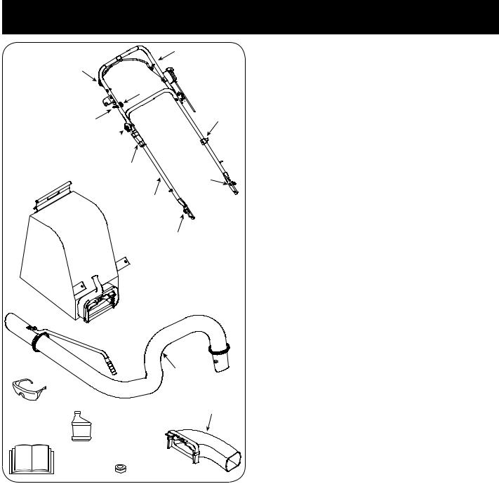
LOOSE PARTS IN CARTON
(See Figure 1)
a.Upper and Lower Handle
b.Hose Assembly
c.Safety Glasses
d.Engine Oil (May be located in bag)
e.Bag
f.Blower Chute
g.Operator’s Manual
h.FreshStart™ Cartridge
Figure 1

#ARRIAGE 3CREW
7ING .UT
(ANDLE "RACKET |
(AIRPINR#LIP |
Figure 2
Rope Guide
B
A
ASSEMBLY
ATTACHING THE HANDLE
1.Remove the hairpin clips from the handle brackets and remove the carriage screws and wing nuts from the lower handle.
a.Place the bottom holes in lower handle over the pins on the handle brackets and secure with hairpin clips. See Figure 2.
b. Insert carriage screws through upper hole in lower handle from the inside and secure with wing nuts. See Figure 2.
2.a. Unfold the upper handle until it aligns with lower handle. Make sure the rope guide is on the right side of upper handle. See Figure 3.
IMPORTANT: Make sure the cables are routed outside the lower handle. Also, do not crimp the cables while lifting up the handles.
b. Secure the two handles by tightening the handle knobs (carriage bolts must be seated properly into the handle). See Figure 3.
3.Pull the two cable ties attached to the cables tight approximately 8 inches from each cable end and place the cables into the cable guide. See Figure 3.
4.Loosen the wing nut that secures the rope guide to the right side of upper handle.
a.Pull the starter rope out of the engine slowly. See Figure 4.
b.Slip the starter rope into the rope guide. Tighten the wing nut. See Figure 4.
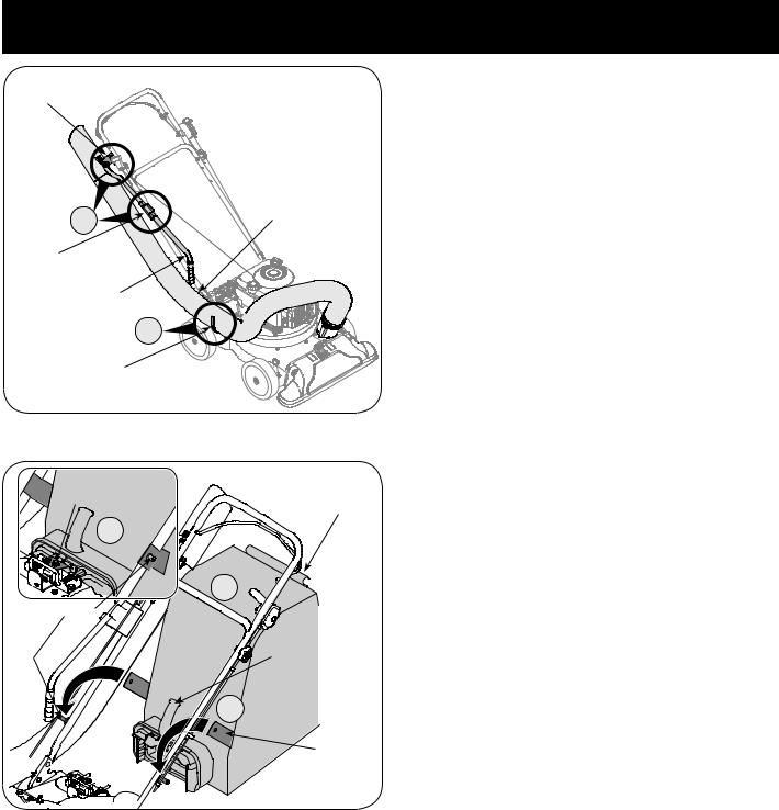
ATTACHING THE HOSE
ASSEMBLY
5.a. Slide hose adapter of hose assembly into the base adapter located on the left front of the Yard Vacuum. See Figure 5.
b.Pull spring loaded pin out on the base and align pin with the first hole (closest to the end of the tube) in the hose adapter.
c.Release the pin to lock the hose in place.
Figure 3
B 
A
A
Align pin with this hole.
B
Figure 4 |
Figure 5 |
ASSEMBLY
Upper
Hose
Handle
Bracket
Lower |
A |
Hose |
|
||
Hose |
|
|
Handle |
|
|
Bracket |
Hose |
|
|
|
|
|
Handle |
|
|
|
B |
|
Hangar |
|
|
Bracket |
|
|
|
Figure 6 |
Bag/Chute
Switch Button Bag
Clip
A
B
Stud
Bag
Handle
C
Strap
6.a. Snap the hose handle first into the upper hose handle bracket and then into the lower hose handle bracket.
b.Lay hose tubing on hanger bracket next to chipper chute. See Figure 6.
ATTACHING THE BAG
7.Grasp bag handle with one hand and slide locking rod on mounting bracket with other hand toward engine. Use the end of mounting bracket as leverage when sliding the locking rod.
a.Slip bag over the rim of the discharge opening and release locking rod to secure bag in place. See Figure 7.
b.Snap bag clip to the top of the lower handle.
c.Place the lower straps on the bag over the top of lower handle, hooking them on the studs. See Figure 7.
NOTE: The bag/chute switch button attached to the mounting bracket must be fully depressed by the tip of front tab on bag handle when securing the bag or engine will not start.
Figure 7

ASSEMBLY
ATTACHING THE BLOWER CHUTE
NOTE: The bag must be removed before installing the blower chute.
8.a. Grasp blower chute with one hand and slide locking rod on mounting bracket with other hand toward engine. Use the end of mounting bracket as leverage when sliding the locking rod. See Figure 8.
b.Slip blower chute over rim of discharge opening and release locking rod to secure chute in place, as in Figure 8.
c.Raise the nozzle height to the highest setting when using the blower chute. Refer to nozzle height adjustment in the ADJUSTMENT section on page 16.
NOTE: The bag/chute switch button attached to the mounting bracket must be fully depressed by the tip of front tab on the blower chute or engine will not start.
 B A
B A 
B
Figure 8

OPERATION
Drive Control
Speed Control
Starter Handle |
|
Bag |
Throttle Control Choke Control |
|
|
|
Bag Handle |
|
|
Oil Fill |
|
Hose |
Gasoline Fill |
|
|
|
|
Handle |
Hose |
|
|
|
|
|
Assembly |
Blower |
Chipper Chute |
Nozzle/Hose |
|
||
|
Vac Lever |
|
Chute |
|
|
|
Nozzle |
|
|
|
|
|
Nozzle Height |
|
|
Adjustment Lever |
|
|
Figure 9 |
|
Now that you have set up your yard vacuum for operation, get acquainted with its controls and features. These are described below and illustrated on this page. This knowledge will allow you to use your new equipment to its fullest potential.
WARNING: The operation of any chipper shredder can result in foreign objects being thrown into the eyes, which can damage your eyes severely. Always wear the safety glasses provided with this unit or eye shields while operating or while performing any adjustments or repairs.
Speed Control
Located on the left side of the upper handle, the speed control is used to select the forward speed of the yard vacuum.
IMPORTANT: Move the speed control only when the engine is running. Changing the speed control setting with the engine off can damage the yard vacuum.
Nozzle Height Adjustment Lever
Used to adjust the nozzle ground clearance ranging approximately from 5/8” to 4 1/8”. See Figure 9.
Throttle Control
Chipper Chute
Allows twigs and small branches up to 1-1/2” in diameter to be fed into the impeller for chipping. See Figure 9.
Drive Control
Located on the underside of the upper handle, the drive control is used to engage/disengage wheels. Fully squeeze the drive control against the upper handle to engage the wheels; release to disengage. (DO NOT slip clutch).
This lever controls the engine speed and stop function. Through three separate positions on the lever from left to right, the operation is as follows:
34/0
3TART 2UN |
3LOW O)DLE |
%NGINE /FF |
Meets ANSI Safety Standards
Craftsman Yard Vacuums conform to the safety standard of the American National Standards Institute (ANSI).
10
OPERATION
Choke Control
The choke control is used to choke the carburetor and assist in starting the engine.
Starter Handle
Used to start the engine.
Nozzle
Yard waste such as leaves or pine needles can be vacuumed up through the nozzle for shredding.
Hose Assembly
Used as an alternative to the nozzle to vacuum yard waste such as leaves or pine needles in hard to reach places. See Figure 9.
Nozzle/ Hose Vac Lever
The nozzle/hose vac handle is located on top of the nozzle. Use it to switch vacuum suction between the nozzle and the hose assembly.
Hose Handle
Used to guide hose assembly when vacuuming.
Bag Handle
Used to grasp bag in order to assist in attaching, removing, and emptying bag. See Figure 9.
Bag
Collects shredded material fed through the chipper chute or vacuumed through the nozzle or hose.
Blower Chute
When attached to unit, the blower chute is used to discharge yard waste such as leaves, pine needle, or small twigs across yard.
GAS AND OIL FILL-UP
Oil (one bottle shipped with unit)
First Time Use
1.Remove oil fill dipstick.
2.With the Yard Vacuum on level ground, use a funnel to empty entire contents of oil bottle provided into the engine.
3.Replace oil fill dipstick and tighten.
Subsequent Uses
Only use high quality detergent oil rated with API service classification SF, SG, or SH. Select the oil’s SAE viscosity grade according to the expected operating temperature. Follow the chart below.
#OLDER |
& |
7ARMER |
|
7 |
3!% |
|
/ILI6ISCOSITYS#HART |
|
Although multi-viscosity oils (5W30, 10W30, etc.) improve starting in cold weather, they will result in increased oil consumption when
used above 32°F. Check your engine oil level more frequently to avoid possible engine damage from running low on oil.
1.Check the oil level making certain not to rub the dipstick along the inside walls of the oil fill tube. This would result in a false dipstick reading. Refill to FULL mark on dipstick, if necessary. Capacity
is approximately 18 oz. Overfilling will cause the engine to smoke profusely and will result in poor engine performance.
2.Replace oil fill dipstick and tighten.
3.Keep oil level at FULL. Running the engine with too little oil can result in permanent engine damage.
Gasoline
1.Remove fuel cap from the fuel tank.
2.Make sure the container from which you will pour the gasoline is clean and free from rust or foreign particles. Never use gasoline that may be stale from long periods of storage in its container.
Gasoline that has been sitting for any period longer than four weeks should be considered stale.
3.Fill fuel tank with clean, fresh, unleaded regular gasoline only. Do not use gasoline containing METHANOL. Replace fuel cap.
IMPORTANT: To avoid engine problems, the fuel system should be emptied before storage for 30 days or longer. Drain the fuel from the tank by running the engine until the fuel tank is empty. Use fresh fuel next season. See STORAGE section for additional information.
NOTE: Check the fuel level periodically to avoid running out of gasoline while operating the Yard Vacuum. If the unit runs out of gas as it is chipping, it may be necessary to unclog the discharge area before it can be restarted. Refer to SERVICE AND ADJUSTMENT section on page 17.
FreshStart™ Gas Cap
This unit is equipped with a FreshStart™ continuous fuel preserver gas cap which automatically drips continuous fuel preserver into your fuel tank for up to six months depending on conditions, such as temperature, usage patterns, fuel type and blend. To activate the gas cap, follow the instructions below:
1.Snap the fuel preserver cartridge that comes with your unit into the fuel cap.
2.Peel off the white tab from the cartridge.
3.Twist the FreshStart™ cap onto the fuel tank.
When you visually see that the fuel preserver cartridge is empty, replacement cartridges are available through your local Sears Parts & Repair Center and most Sears stores.
WARNING: Use extreme care when handling gasoline. Gasoline is extremely flammable and the vapors are explosive. Never fuel machine indoors or while the engine is hot or running. Extinguish cigarettes, cigars, pipes, and other sources of ignition.
11

OPERATION
4HROTTLE #ONTROL
#HOKEO#ONTROL
TO STOP ENGINE
1.Move throttle control lever to STOP or OFF position.
2.Disconnect spark plug wire and ground it to the retaining post to prevent accidental starting while the equipment is unattended.
WARNING: When moving throttle control lever, be careful of heated surfaces and sharp edges on muffler guard.
Figure 10
B
D
 C
C
A
Figure 11

 Buttons
Inner


 Flap
Flap
Outer Flap
Figure 12
TO START ENGINE
1.Attach spark plug wire and rubber boot to spark plug.
2.The bag/chute switch button must be fully depressed by the tip of front tab on bag handle or blower chute for engine to start.
3.Make sure bag/chute switch wire is connected to engine and grounded to mounting bracket.
4.Gas tank should be filled 3/4 to full before starting.
5.Move throttle control to START/RUN (Rabbit) position. See Figure 10.
6.Move the choke control toward the throttle control to choke the engine’s carburetor. (A warm engine may not require choking.) See Figure 10.
7.Standing behind the unit, grasp starter handle and pull rope out until you feel a drag.
8.Pull the rope with a rapid, continuous, full arm stroke. Keep a firm grip on the starter handle. Let the rope rewind slowly.
9.Repeat, if necessary, until engine starts. When engine starts, move choke control gradually away from the throttle control.
10.If engine falters, move choke control back toward the throttle control and repeat steps 7 through 9.
11.ALWAYS keep the throttle control in the START/RUN position when operating the Yard Vacuum.
TO EMPTY BAG
1.a. Unhook bag straps from the lower handle.
b.Unsnap bag clip from the top of lower handle. See Figure 11.
c.Grasp bag handle with one hand and pull lock rod on mounting bracket with other hand toward engine to release.
d.Lift bag off back of unit.
2.Twist the two buttons on the back of the bag to unlock and empty contents. See Figure 12. Hold bag handle and bag clip while emptying the contents.
3.Compress bag opening and fold inner flap over opening.
4.Fold outer flap over inner flap and insert buttons on the bag through metal outlets. See Figure 12.
5.Twist the buttons to lock bag. Place bag back onto unit as instructed on page 8.
12

OPERATION
TO REMOVE BLOWER CHUTE
1.Grasp blower chute with one hand and pull lock rod on mounting bracket with other hand toward engine to release. Refer to Figure 7.
2.Remove blower chute from over the rim of the discharge opening.
USING THE NOZZLE VACUUM
1.Place nozzle/hose vac lever in the top position on the nozzle to vacuum through nozzle. See Figure 13.
2.The spring loaded pin must be in the first hole (closest to the end of the tube) of the hose adapter to operate the nozzle vac.
3.Place both hands on top of the upper handle and fully lift the drive control against the upper handle to propel the unit over yard.
4.Use the speed control to choose either the high or low speed. The speed control may be moved either while the unit is propelling or before engaging the wheels.
IMPORTANT: Move the speed control only when the engine is running. Changing the speed control setting with the engine off can damage the yard vacuum.
Yard waste such as leaves and pine needles can be vacuumed up through the nozzle for shredding. After material has been shredded by the flail blades on the impeller assembly, it will be discharged into catcher bag or through blower chute. Do not attempt to shred or chip any material other than vegetation found in a normal yard (i.e. branches, leaves, twigs, etc.) Avoid fibrous plants such as tomato vines until they are thoroughly dried out. Materials such as stalks or heavy branches up to 1-1/2” in diameter may be fed into the chipper chute.
WARNING: Do not attempt to shred, chip, or vacuum any material larger than specified on the machine or in this manual. Personal injury or damage to the machine could result.
.OZZLE (OSEE |
(OSE |
|
!DAPTER |
||
6AC ,EVER |
||
|
||
4OP 0OSITION |
|
|
|
|
.OZZLE
3PRING ,OADED 0INO&IRST (OLE
Figure 13
.OZZLE (OSE 6AC ,EVER"OTTOMT0OSITION 0 


3PRING ,OADED 0INO3ECONDC(OLE
IMPORTANT: The flail screen is located inside the housing in the |
Figure 14 |
discharge area. If the flail screen becomes clogged, remove and clean |
|
as instructed in the Service & Adjustments section on page 17. For |
|
best performance, it is also important to keep the chipper blade sharp. |
|
WARNING: Do not at any time make any adjustments without first stopping engine and disconnecting spark plug wire.
USING THE HOSE ASSEMBLY
1.Place nozzle/hose vac handle in the bottom position on the nozzle to redirect vacuum to the hose assembly. See Figure 14.
2.The spring loaded pin must be in the second hole of the hose adapter to operate the hose assembly.
3.Unhook the hose from upper handle bracket and grasp the hose handle to guide while vacuuming yard waste such as leaves or pine needles in hard to reach places.
13

MAINTENANCE
CLEAN EQUIPMENT

 !IRI#LEANERL (OUSING
Figure 15
1.Clean the Yard Vacuum thoroughly after each use.
2.Wash bag periodically with water. Allow to dry thoroughly in shade.
3.If the flail screen becomes clogged, remove and clean as instructed in the SERVICE AND ADJUSTMENTS section.
NOTE: Cleaning with a forceful spray of water is not recommended as it could contaminate the fuel system.
CHECK ENGINE OIL
1.Stop engine and wait several minutes before checking oil level. With engine on level ground, the oil must be to FULL mark on dipstick.
2.Remove oil fill dipstick.
3.Check oil level on dipstick. Level should be at FULL mark. (If not, see “Subsequent Uses” on page 11).
4.Replace oil fill dipstick and tighten.
GENERAL RECOMMENDATIONS
1.Always observe safety rules when performing any maintenance.
2.The warranty on this yard vacuum does not cover items that have been subjected to operator abuse or negligence. To receive full value from warranty, operator must maintain the equipment as instructed here.
3.Some adjustments will have to be made periodically to maintain your unit properly.
4.Periodically check all fasteners and make sure these are tight.
WARNING: Always stop engine and disconnect spark plug wire before performing any maintenance or adjustments. Always wear safety glasses during operation or while performing any adjustments or repairs.
LUBRICATION
1.Wheels- Place a few drops of SAE 30 oil on each shoulder screw once a season. Refer to Figure 23 on page 18.
2.Nozzle height adjustment levers- Lubricate nozzle height adjustment levers with light oil. Refer to Figure 9.
3.Locking Rod- Lubricate the lock rod and compression springs which attach to the mounting bracket. Refer to Figure 8.
CHANGE ENGINE OIL
•Only use high quality detergent oil rated with API service classification SF, SG, or SH. Select the oil’s SAE viscosity grade according to the expected operating temperature. Refer to operation section for viscosity chart.
•Change engine oil after the first five hours of operation, and every twenty-five hours thereafter.
TO DRAIN OIL
Drain oil while engine is warm. Follow the instructions given below:
1.Drain the fuel from the tank by running the engine until the fuel tank is empty.
2.Remove oil fill dipstick.
3.Tip unit on its side to drain through the oil fill tube.
4.When engine is drained of all oil, refill with approximately 18 oz. of fresh oil. Refer to Gas And Oil Fill-Up in OPERATION section.
5.Replace oil fill dipstick and tighten.
SERVICE AIR CLEANER
The air cleaner prevents damaging dirt, dust, etc., from entering the carburetor and being forced into the engine and is important to engine life and performance. The air cleaner consists of a pleated filter. Never run the engine without an air cleaner completely assembled.
To Service Air Cleaner:
1.Loosen screw and tilt plastic housing cover on side of engine down. See Figure 15.
14

MAINTENANCE
2.Remove pleated filter from plastic housing cover and replace with clean or new filter.
3.Tilt cover up into place and tighten screw.
NOTE: If the filter is torn or damaged in any way, replace it.
WARNING: Temperature of muffler and nearby areas may exceed 150˚ F (65˚C). Avoid these areas.
SERVICE SPARK PLUG
Clean the spark plug and reset the gap to .030” at least once a season or every 50 hours of operation. See Figure 15. Spark plug replacement is recommended at the start of each season. Refer to engine parts list for correct spark plug type.
NOTE: Do not sandblast spark plug. Spark plug should be cleaned by scraping or wire brushing and washing with a commercial solvent.
SERVICE MUFFLER
•Inspect muffler periodically, and replace if necessary.
•If your engine is equipped with a spark arrester screen assembly, remove after every 50 hours of use for cleaning and inspection. Replace if damaged.
WARNING: Do not operate the Yard Vacuum without a muffler or tamper with the exhaust system. Damaged mufflers or spark arresters could create a fire hazard.
CLEAN ENGINE
•Clean engine by removing dirt and debris with a cloth or brush.
•Frequently remove grass clippings, dirt, and debris from cooling fins, air intake screen, levers, and linkage. This will help ensure adequate cooling and engine speed.
|
|
|

MM 'AP%LECTRODES
0ORCELAIN
Figure 16
15

SERVICE & ADJUSTMENTS
.OZZLE (EIGHT 


 !DJUSTMENT


 ,E
,E VER
VER


.OZZLE
Figure 17
! $RIVEI#ONTROL


 ! " #
! " #
"
$RIVEI#ONTROL
: &ITTING
&RONTO(OLE
2EAR (OLE |
$RIVEI#ONTROL##ABLE |
|
|
|
Figure 18 |
WARNING : Do not at any time make any adjustment to the unit without first stopping engine and disconnecting spark plug wire.
NOZZLE HEIGHT ADJUSTMENT
The nozzle can be adjusted to any six positions, ranging from 5/8” to 4 1/8” ground clearance. The nozzle height has to be adjusted according to yard conditions.
1.Depress nozzle height adjustment lever towards wheel. See Figure 17.
2.Move the height adjustment lever forward or backward to adjust the nozzle upwards or downwards. Make sure both levers are in the same position.
3.Release lever towards deck.
NOTE: In general, raise the nozzle height to vacuum a thick layer of leaves or to operate with the blower chute. Lower the nozzle height for smoother surfaces.
DRIVE CONTROL CABLE ADJUSTMENT
Adjust the drive control cable if the yard vacuum does not self propel with the drive control engaged, or if the unit hesitates while the engine maintains the same speed after approximately 20 hours of use.
To move the z-fitting of the drive control cable from its factory set position in the front hole of the drive control to the rear hole, proceed as follows:
1.a. Push the right side of the control out of the right hole in the upper handle. See Figure 18A.
b.Pivot control down towards the lower handle.
c.Pivot straight up to remove it from the left hole in the upper handle. See Figure 18A.
2.Grasp the z-fitting with your hand and move it from the front hole to the rear hole of the drive control. See Figure 18B.
IMPORTANT: Make sure to insert the z-fitting into the rear hole as it was inserted in the front hole, that is from the outside of the drive control.
3.Reinstall the drive control by performing the previous steps in the opposite order and manner of removal.
IMPORTANT: Once assembled and prior to restarting, make sure that the cable is properly adjusted. With the drive control disengaged, the unit should freely pull in reverse.
16
SERVICE & ADJUSTMENTS
CARBURETOR ADJUSTMENT
WARNING: If any adjustments (e.g. carburetor) are made to the engine while the engine is running, keep clear of all moving parts. Be careful of heated surfaces and muffler.
The carburetor has been pre-set at the factory and should not require adjustment. If your engine does not operate properly due to suspected carburetor problems, take your Yard Vacuum to a Sears Parts & Repair Center for repair and adjustment.
ENGINE SPEED
The engine speed on your Yard Vacuum has been set at the factory. Do not attempt to increase the engine RPM. If you think that the engine is running too fast or too slow, take your Yard Vacuum to the nearest Sears Parts & Repair Center for repair and adjustment.
WARNING: Do not attempt to alter the engine speed by tampering with the engine’s governor linkage. Doing so could result in serious personal injury and damage to the engine. The engine RPM has been set at the factory.
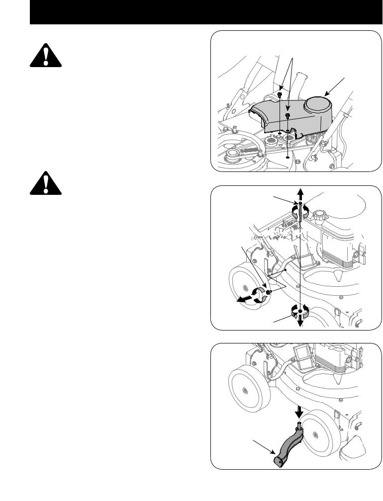
REMOVING THE FLAIL SCREEN
If the discharge area becomes clogged, remove the flail screen and clean area as follows.
1.Stop the engine. Make certain the chipper/shredder vacuum has come to a complete stop.
2.Before unclogging the discharge chute, disconnect and ground the spark plug wire to retaining post.
3.Remove the vacuum bag or blower chute from the unit as instructed in the OPERATION section to obtain access to flail screen.
4.Remove the three self tapping screws securing the belt cover, and remove the belt cover. See Figure 19.
5.Remove self tapping screw on right side of unit that attaches to the flail screen. See Figure 20.
6.Remove hex screw on top of rear housing near mounting bracket and the flange lock nut that secures flail screen. See Figure 20.
7.Remove and clean the screen by scraping or washing with water. See Figure 21.
8.Reinstall the screen.
3ELF
4APPING
3CREWS
"ELT #OVER
Figure 19
(EXE3CREW
3ELF 
4APPING


3CREW 


&LANGE ,OCK .UT
Figure 20
&LAILA3CREEN
Figure 21
17
 Loading...