


XD3 RGB
WEB: corsair.com |
BLOG: corsair.com/blog |
PHONE: (888) 222-4346 |
FORUM: forum.corsair.com |
SUPPORT: support.corsair.com |
YOUTUBE: youtube.com/corsairhowto |
© 2019 CORSAIR MEMORY Inc. All rights reserved. CORSAIR and the sails logo are registered trademarks in the United States and/or other countries. All other trademarks are the property of their respective owners. Product may vary slightly from those pictured. 49-002027 AA
BETTER
TOGETHER
corsair.com/downloads
XD3 RGB
Pump/Reservoir Combo

ENGLISH........................................................ |
1 |
FRANÇAIS................................................... |
11 |
DEUTSCH.................................................... |
21 |
ITALIANO..................................................... |
31 |
ESPAÑOL..................................................... |
41 |
PУССКИЙ...................................................... |
51 |

ENGLISH
IMPORTANT NOTICE |
PREREQUISITES (NOT INCLUDED) |
Quick Start Guide is a general installation guide and does not cover the specifics of individual case or radiator mounting.
CORSAIR recommends you thoroughly leak-test your custom cooling system for at least 24 hours to ensure that the system is securely sealed and operating reliably. CORSAIR warranty does not cover any hardware damage resulting from poorly executed, improper and otherwise hasty assembly of your custom water-cooling system.
Disassembly of CORSAIR HYDRO products is highly discouraged due to complex design of components. Such action may result in irreparable mechanical, electrical or chemical damage that may void the warranty.
For an exact and up-to-date product compatibility list, please refer to CORSAIR website. |
|
M |
O |
||||
PACKAGE CONTENTS |
|
|
|
|
|
|
|
|
A |
B |
|
C |
D |
E |
|
|
|
|
|
|
|
N |
|
F |
G |
H |
I |
J |
K |
L |
|
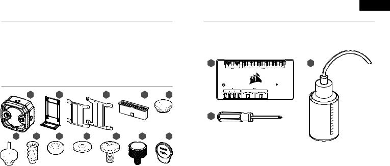
A — x1 XD3 RGB PUMP/RESERVOIR |
G — |
x4 FAN SELF-TAPPING SCREW |
M — CORSAIR iCUE COMMANDER PRO SMART RGB LIGHTING AND FAN SPEED CONTROLLER |
|
|||
B — x1 PERPENDICULAR MOUNTING BRACKET |
H — |
x4 M4 HEX NUT |
N — PHILLIPS-HEAD SCREWDRIVER |
|
|||
C — x1 120mm & 140mm FAN MOUNTING ADAPTER PLATE |
I — |
x4 M4 WASHER |
O — FILLING FLASK & CORSAIR XL5 COOLANT |
|
|||
D — x1 ATX 24 - PIN PSU JUMPER BRIDGE |
J — |
x4 M4x8mm SCREW |
|
E — x3 CORSAIR G1/4˝ PLUGS |
K — |
x8 M3 THUMB SCREW |
Note: CORSAIR iCUE Commander PRO or CORSAIR Lighting Node PRO are required for driving and controlling |
|
|
|
the RGB LED illumination. CORSAIR iCUE Commander PRO is required for automatic control of the pump and |
F — x1 CORSAIR G1/4˝ TEMPERATURE SENSOR PLUG |
L — |
x1 PLUG TOOL |
for monitoring the liquid temperature using iCUE software suite. |
|
|
|
|
1 |
2 |
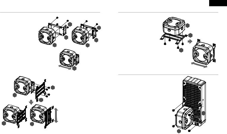
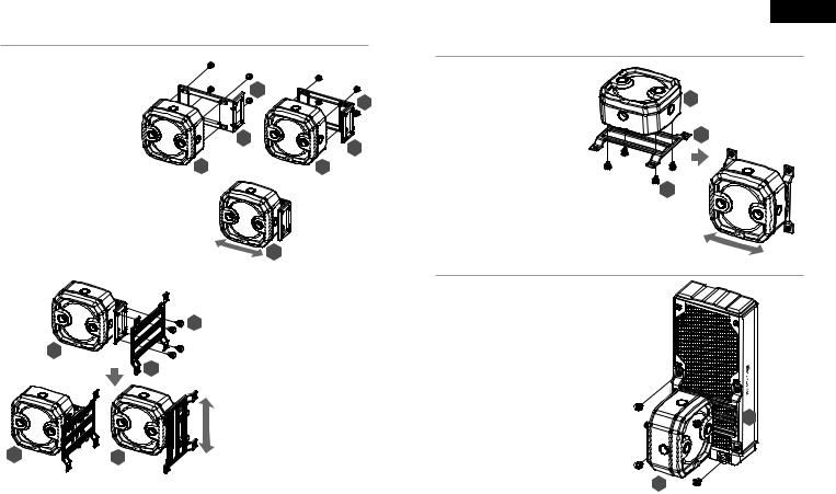
MOUNTING THE XD3 RGB TO PERPENDICULAR MOUNTING BRACKET
1.Secure the Perpendicular mounting bracket (B) to the XD3 RGB (A) using four (4) M3 thumb screws (K).
2.The Perpendicular mounting bracket can be oriented in two ways and allows free movement along the horizontal axis.
A
C
A  A
A
Horizontal
K
K
B
B
A  A
A
A
3.Secure the XD3 RGB (A) with the perpendicular mounting bracket onto a 120mm or 140mm fan mounting adapter plate (C) using four M3 thumb screws (K).
K4. The fan adapter brackets can be mounted horizontally or vertically thus allowing free movement along the horizontal or vertical axis (depending on orientation).
Vertical
3
ENGLISH
MOUNTING THE XD3 RGB TO A FAN MOUNTING ADAPTER PLATE
1. Place the XD3 RGB (A) on the 120mm or 140mm fan mounting adapter plate (C). Secure the XD3 RGB to the mounting adapter plate using four M3
thumb screws (K).
A
2. The fan adapter brackets can be mounted horizontally thus allowing free movement along the horizontal axis.
C
K
MOUNTING THE XD3 RGB TO A CORSAIR XR RADIATOR
Secure the XD3 RGB (A) with the preinstalled 120mm or 140mm fan mounting adapter plate
(C) to the CORSAIR XR radiator with the short 6mm (0.25˝) M4XP0.7 screws supplied with the CORSAIR XR radiator itself.
C
A
4

MOUNTING THE XD3 RGB TO A CASE FAN
Secure the XD3 RGB (A) with the preinstalled 120mm |
|
or 140mm fan mounting adapter plate (C) to a fan |
|
using four enclosed self-tapping fan screws (G). |
C |
|
A
G
MOUNTING THE XD3 RGB DIRECTLY TO A CASE FAN SLOT
Secure the XD3 RGB (A) with the preinstalled 120mm or 140mm fan mounting adapter plate (C) onto a case fan opening. Use the enclosed M4x8mm screws (J) along with washers (I) and M4 hex nuts (H).
C
A 
 H
H
I
J
5
ENGLISH
MOUNTING THE XD3 RGB DIRECTLY TO A CASE FAN SLOT
Locate the suitable cut-out hole pattern in the chassis that would fit 88mm x 55mm hole pattern (if mounting the XD3 RGB directly) or 27.5mm x 55mm if using the perpendicular mounting bracket.
If there are no hole patterns available, there is an option to drill the holes using a Ø3,4mm - Ø4mm drill bit. Secure the unit by screwing four M3 thumb screws (K).
K
K
A  A
A
XD3 RGB MOUNTING ORIENTATION
The XD3 RGB must be installed vertically (see picture below).
6

FINALIZING THE SETUP
1.Install the two (2) appropriate CORSAIR XF G1/4 BSPP threaded-type fittings (not included) into the reservoir ports and tighten them by hand. Do not use any tools (i.e. pliers) (Figure 1).
2.It is mandatory to use the front-left port as the OUTLET. The recommended INLET (return) port is marked on the image below. Optionally, you can use the top G1/4 port as an INLET (return) line as well (Figure 2 and 3).
3.Install the CORSAIR G1/4 Temperature Sensor Plug (F) into the G1/4 port located on the base of the unit. Do not install the temperature sensor on any of the top ports.
4.Close the remaining three (3) open (unused) ports with the included CORSAIR G1/4 plugs and tighten them using a plug tool (L). Refrain from using a screwdriver as it may result in damage to the surface of the plugs.
Figure 1
INLET
OUTLET |
L |
|
F |
FILL port |
Must be used as |
OUTLET port |
|
Figure 2 |
Figure 3 |
Can be used as |
Temperature |
INLET port |
sensor |
ENGLISH
CONNECTING THE PUMP AND USING THE INTEGRATED DIGITAL RGB ILLUMINATION
A CORSAIR iCUE Commander PRO or Lighting Node PRO (either) is required in order to use the integrated RGB illumination on
the XD3 RGB. CORSAIR iCUE software is used to program the visual effects. CORSAIR iCUE Commander PRO is required for automatic control of the pump and for monitoring the liquid temperature using iCUE software suite.
The XD3 RGB Pump/Reservoir can be connected to the appropriate CORSAIR controller either directly or "daisy"-chained with other CORSAIR addressable RGB component(s).
1.Identify the correct RGB connector on the reservoir-pump unit (Figure 1).
2.Insert the RGB connector in a CORSAIR iCUE Commander PRO port or Lighting Node PRO port (Figure 2).
3.Download and install CORSAIR iCUE software suite from the following website: https://www.corsair.com/icue. Configure visual and lighting effects by following the manual for iCUE software.
4.Connect the XD3 RGB’s pump 4-pin fan connector into Fan Port #6 on your CORSAIR iCUE Commander PRO (Figure 3).
5.Connect the XD3 RGB’s temperature sensor into temperature Port #1 on your CORSAIR iCUE Commander PRO (Figure 4).
6.Connect the XD3 RGB’s main power cable by plugging in a 4-pin Molex connector from your power supply (Figure 5).
Figure 1
Direct Attach (IN)
 Daisy Chain (to NEXT)
Figure 2 |
Figure 3 |
Figure 4 |
Figure 5 |
PSU
XD3 RGB
7 |
8 |

FILLING AND PRIMING THE XD3 RGB
1.Disconnect PSU power cables from all computer components except the XD3 RGB 4-pin Molex power connector. Make sure the PSU is turned OFF, either at the plug socket, or via the toggle switch on the rear of the PSU. Connect the enclosed ATX 24-pin PSU Jumper Bridge starter to your PSU 24-pin ATX cable. This will allow you to power on your XD3 RGB without powering on the PC (Figure 1).
2.Fill the reservoir through the top G1/4 opening with CORSAIR XL5 coolant using a filling flask to about 0.5cm (1/5˝) below the top (Figure 2).
3.Turn on the power by flipping the ON switch on the PSU. The pump motor will be primed with coolant from the reservoir and will start flowing through the system. Turn the power OFF before the reservoir is emptied. Do not let the pump run dry or without coolant in the reservoir as this will damage the pump (Figure 3)!
4.Repeat steps 2 and 3 until your custom cooling system is full. CORSAIR recommends not to fill the reservoir more than about 0.5cm (1/5˝) from the top.
5.Once the system is filled with coolant, CORSAIR recommends running it for 24 hours to remove any air trapped in the components and to make sure there are no leaks in the system. Once you have thoroughly leak-tested the system, turn OFF the PSU and disconnect ATX 24-pin PSU Jumper Bridge. Reconnect the power to other computer peripherals and start the computer.
Figure 1
D
Figure 2
Figure 3
ENGLISH
FAQ
1.Can I use the XD3 RGB as a standalone part?
No, this is a water-cooling pump with integrated reservoir which requires a complete custom water-cooling system, including cold plates (water blocks) and radiator. For more information, please visit corsair.com.
2.Can I use the XD3 RGB with aluminium water-cooling equipment?
No, you cannot. Certain parts are made from copper and brass and should not be mixed with aluminium.
3.Can I connect the RGB header directly to my motherboard?
No, you cannot. The RGB function is only compatible with the CORSAIR iCUE Commander PRO and the CORSAIR Lighting Node PRO controllers.
4.Can the XD3 RGB pump be controlled without the use of CORSAIR iCUE Commander PRO?
While it is possible to use XD3 RGB without a CORSAIR iCUE Commander PRO, doing so will remove the automated pump speed control in CORSAIR iCUE software. The pump speed may be manually controlled by motherboard UEFI when XD3 RGB’s 4-pin fan PWM connector is connected.
5.How many RGB devices can I daisy-chain to a single channel on a CORSAIR controller?
CORSAIR recommends you connect no more than three (3) Hydro X Series RGB devices of any type connected in a series on a single channel. However, you can connect one (1) XC7/XC9 water block, two (2) XG7 RGB water blocks and one (1) XD3 RGB pump unit for a total of four (4) devices. Do not mix CORSAIR fans or RGB LED strips and CORSAIR HYDRO X products on the same channel on the controller. Use a dedicated channel for other components.
9 |
10 |
FRANÇAIS
AVIS IMPORTANT |
MATÉRIEL NÉCESSAIRE (NON INCLUS) |
Ce Guide de démarrage rapide est un guide général d’installation et ne traite pas des détails des cas individuels ou de montage de radiateur.
CORSAIR vous recommande de tester minutieusement l’étanchéité de votre circuit de refroidissement personnalisé pendant au moins 24 heures pour vous assurer que le circuit est absolument hermétique et fonctionne de façon fiable. La garantie CORSAIR ne couvre pas tout dommage matériel résultant d’un montage mal exécuté, inadéquat ou trop rapide de votre circuit de refroidissement à eau personnalisé.
Le démontage des produits CORSAIR HYDRO est vigoureusement déconseillé à cause de la conception complexe des composants. Cette action peut entraîner des dommages mécaniques, électriques ou chimiques irréparables, qui peuvent annuler la garantie.
Pour une liste exacte et actualisée de compatibilité des produits, veuillez consulter le site web CORSAIR.
CONTENU DE L’EMBALLAGE
A B C D E
F G H I J K L
M O
N
A — POMPE/RÉSERVOIR XD3 RGB x1 |
G — |
VIS AUTOTARAUDEUSE POUR |
M — CONTRÔLEUR DE VITESSE DU VENTILATEUR ET DE LA LAMPE INTELLIGENTE RGB CORSAIR |
B — SUPPORT DE MONTAGE PERPENDICULAIRE x1 |
|
LE VENTILATEUR x4 |
iCUE COMMANDER PRO |
|
|
|
|
C — PLAQUE D'ADAPTATION POUR LE MONTAGE DU |
H — |
ÉCROU HEXAGONAL M4 x4 |
N — TOURNEVIS CRUCIFORME PHILLIPS |
|
|
|
|
VENTILATEUR 120mm et 140mm x1 |
I — |
RONDELLE M4 x4 |
O — BALLON DE REMPLISSAGE ET LIQUIDE DE REFROIDISSEMENT CORSAIR XL5 |
D — PONT DE CAVALIER DE LA BROCHE DU BLOC |
J — |
VIS M4x8mm x4 |
|
D'ALIMENTATION - ATX 24 x1 |
K — |
VIS PAPILLON M3 x8 |
Note: Le CORSAIR iCUE Commander PRO ou le CORSAIR Lighting Node PRO sont nécessaires pour activer et |
|
|||
E — PRISES CORSAIR G1/4˝ x3 |
L — |
OUTIL POUR PRISES x1 |
contrôler l’éclairage LED RGB. Le CORSAIR iCUE Commander PRO est nécessaire pour le contrôle automatique |
|
de la pompe et pour surveiller la température du liquide en utilisant la suite logicielle iCUE. |
||
F — PRISE DU CAPTEUR DE TEMPÉRATURE CORSAIR G1/4˝ x1 |
|
|
|
|
|
|
|
11 |
12 |
MONTAGE DU XD3 RVB SUR LE SUPPORT DE MONTAGE PERPENDICULAIRE
1.Fixez le support de montage perpendiculaire (B) à la pièce XD3 RVB (A) l'aide de quatre (4) vis à oreilles M3 (K).
2.Vous pouvez orienter le support de montage perpendiculaire de deux manières, ce qui lui permet un mouvement libre le long de
l'axe orizontal.
A
C
A  A
A
Horizontal
K
K
B
B
A  A
A
A
3.Fixez l'XD3 RVB (A) avec le support de montage perpendiculaire sur une
plaque d’adaptation pour le montage du ventilateur de 120mm ou de 140mm (C)
Kà l’aide de quatre vis à oreilles M3 (K).
4.Les supports d'adaptation de ventilateur peuvent être fixés horizontalement
ou verticalement, permettant ainsi un mouvement libre le long de l'axe horizontal ou vertical (en fonction de l'orientation).
Vertical
13
FRANÇAIS
MONTAGE DU XD3 RVB SUR LA PLAQUE D'ADAPTATION POUR LE MONTAGE SUR LE VENTILATEUR
1.Placez le XD3 RVB (A) sur la plaque d’adaptation pour le montage du ventilateur de 120mm ou 140mm (C). Fixez l'XD3 RVB à la plaque d'adaptation
à l'aide de quatre vis à oreilles M3 (K). |
A |
2. Les supports d'adaptation du ventilateur |
|
peuvent être fixés horizontalement ce |
|
qui leur permet un mouvement libre le |
C |
long de l'axe horizontal. |
K
MONTAGE DU XD3 RGB SUR UN CORSAIR RADIATEUR
Fixez l'XD3 RVB (A) à l'aide de la plaque d'adaptation pour le montage du ventilateur de 120 ou de 140mm (C) sur la radiateur CORSAIR XR à l'aide des vis courtes M4XP0.7
de 6mm (0.25˝) fournies avec le radiateur même CORSAIR XR.
C
A
14

MONTAGE DU XD3 RGB SUR UN CORSAIR VENTILATEUR BOÎTIER
Fixez l'XD3 RVB (A) à l'aide de la plaque d'adaptation préinstallée pour le montage du ventilateur de
120mm ou de 140mm (C) au ventilateur à l'aide des C vis autotaraudeuses fournies (G).
A
G
MONTAGE DU XD3 RGB DIRECTEMENT SUR UN SLOT DE VENTILATEUR BOÎTIER
Fixez l'XD3 RVB (A) à l'aide de la plaque d'adaptation pour le montage du ventilateur de 120mm ou 140 mm
(C) sur l'ouverture du ventilateur. Utilisez les vis (J) M4x8 mm fournies avec les rondelles (I) et les écrous hexagonaux M4 (H).
C
A 
 H
H
I
J
15
FRANÇAIS
MONTAGE DU XD3 RGB DIRECTEMENT SUR LA TÔLE DU BOÎTIER
Cherchez le modèle de découpe approprié dans le châssis qui convient au modèle de trou de 88mm x 55mm (si vous fixez l'XD3 RVB directement) ou au modèle de trou de 27.5mm x 55mm si vous utilisez le support de montage perpendiculaire.
S'il n'y a aucun modèle de trous disponibles, il est possible de percer les trous à l'aide d'un foret de Ø3,4mm - Ø4mm. Fixez l'unité à l'aide de quatre vis à oreilles M3 (K).
K
K
A  A
A
ORIENTATION DE LA FIXATION DU XD3 RGB
L'XD3 RVB doit être installé verticalement (voir la figure ci-dessou).
16
FINALISATION DE L’INSTALLATION
1.Installez les deux (2) raccords filetés CORSAIR XF G1/4 BSPP appropriés (non inclus) dans les ports du réservoir et serrez-les à la main. N’utilisez aucun outil (tel que des pinces) (Figure 1).
2.Il est obligatoire d’utiliser le port avant-gauche comme port de sortie et tout autre port du bas comme entrée. Le port d’entrée (INLET) recommandé est marqué sur l’image ci-dessous. En option, vous pouvez également utiliser le port G1/4 du haut avec tube intégré comme ligne d’entrée (retour) (Figure 2 et 3).
3.Installez le connecteur de sonde de température CORSAIR G1/4 (F) dans le port G1/4 situé au bas du produit. N’installez pas la sonde de température sur un des ports du haut.
4.Fermez les trois (3) ports ouverts restants (non utilisés) avec les bouchons CORSAIR G1/4 inclus et serrez-les en utilisant une pièce de monnaie (Plug Tool) (L). Retenez-vous d’utiliser un tournevis car cela pourrait entraîner l’endommagement de la surface des bouchons.
Figure 1
ENTRÉE
SORTIE |
L |
|
F |
Port de remplissage |
Doit être utilisé comme |
port de SORTIE |
|
Figure 2 |
Figure 3 |
Peut être utilisé comme |
Capteur de |
port d'ENTRÉE |
température |
FRANÇAIS
RACCORDEMENT DE LA POMPE ET UTILIZATION DE
L’ÉCLAIRAGE DIGITAL RGB INTÉGRÉ
Un CORSAIR iCUE Commander PRO ou un Lighting Node PRO (l’un ou l’autre) est nécessaire afin d’utiliser l‘éclairage RGB intégré
sur le XD3 RGB. Le logiciel CORSAIR iCUE est utilisé pour programmer les effets visuels. Le CORSAIR iCUE Commander PRO est nécessaire pour le contrôle automatique de la pompe et pour surveiller la température du liquide en utilisant la suite logicielle iCUE.
La Pompe/Réservoir XD3 RGB peut être raccordée au contrôleur CORSAIR approprié, soit directement, soit en chaîne dite "guirlande" avec d’autres composants CORSAIR RGB adressables.
1.Identifiez le connecteur RGB approprié sur l’unité pompe-réservoir (Figure 1).
2.Insérez la connexion RGB dans le port d’un CORSAIR iCUE Commander PRO ou d’un Lighting Node PRO. (Figure 2).
3.Téléchargez et installez la suite logicielle CORSAIR iCUE depuis le site web suivant : https://www.corsair.com/icue. Configurez les effets visuels et d’éclairage en suivant le manuel du logiciel iCUE.
4.Connectez le connecteur de ventilateur 4-pin de la pompe XD3 RGB au Port Ventilateur n°6 sur votre CORSAIR iCUE Commander PRO (Figure 3).
5.Connectez la sonde de température du XD3 RGB au Port Température n°1 sur votre CORSAIR iCUE Commander PRO (Figure 4).
6.Connectez le câble d’alimentation principal du XD3 RGB en branchant un connecteur Molex 4-pin venant de votre bloc d’alimentation (Figure 5).
Figure 1
Connexion directe (DANS)
 Connexion en série
(au SUIVANT)
Figure 2 |
Figure 3 |
Figure 4 |
Figure 5 |
PSU
XD3 RGB
17 |
18 |
 Loading...