


|
|
corsair.com |
||
|
|
|
|
|
EMAIL: support@corsair.com |
|
|
|
FORUM: forum.corsair.com |
FACEBOOK: facebook.com/corsairmemory |
|
|
|
TWITTER: twitter.com/corsairmemory |
BLOG: corsair.com/blog/ |
|
|
|
H55 PAGE: corsair.com/h55 |
|
|
|
|
|
|
|
|||
USA and CANADA: (800) 205-7657 | |
INTERNATIONAL: (510) 657-8747 | FAX: (510) 657-8748 |
|||
|
|
|
|
|
46221 Landing Parkway • Fremont • California • 94538 • USA
© 2013 Corsair Components, Inc. All Rights Reserved. The Corsair logo is a registered trademark, and Hydro Series are trademarks of Corsair in the United States and/or other countries. All other names and products are trademarks and property of their respective owners. Printed in China.
Document Number: 49-000182 rev AB
TM
QUICK START GUIDE
GUIDE DE DÉMARRAGE RAPIDE
SCHNELLSTARTANLEITUNG
GUIDA INTRODUTTIVA
GUÍA BREVE DE INICIO
КРАТКОЕ РУКОВОДСТВО
LIQUID CPU COOLING UPGRADE KIT
Note: Most newer PC cases include a CPU cutout to allow access to the bottom of the motherboard. If your case does not include a cutout, you will need to remove your motherboard from the case before installation.
Remarque : la plupart des nouveaux boîtiers de PC comportent un accès facilité au processeur qui permet d'accéder à la base de la carte mère. Si aucun accès n'est prévu sur votre boîtier, vous devrez retirer votre carte mère du boîtier avant de procéder à l'installation.
Hinweis: Bei neueren PC-Gehäusen gibt in der Regel eine CPU-Ö nung Zugang zur Unterseite der Hauptplatine. Falls Ihr Gehäuse keine derartige Ö nung aufweist, müssen Sie vor der Installation die Hauptplatine ausbauen.
Nota: la maggior parte dei più recenti case per PC prevede un ritaglio dietro la CPU che consente l'accesso alla parte inferiore della scheda madre. Se il case non include un ritaglio, occorrerà rimuovere la scheda madre dal case prima di procedere con l'installazione.
Nota: La mayoría de las carcasas de las nuevas PC incluyen una puerta trasera para el CPU a fin
de permitir el acceso a la parte inferior del motherboard. Si su carcasa no tiene esta entrada, deberá retirar el motherboard de la carcasa antes de
la instalación.
Примечание. На большинстве современных корпусов ПК имеется прорезь для предоставления доступа к нижней части материнской платы. Если на вашем корпусе нет такой прорези, то перед установкой необходимо удалить материнскую плату из корпуса.
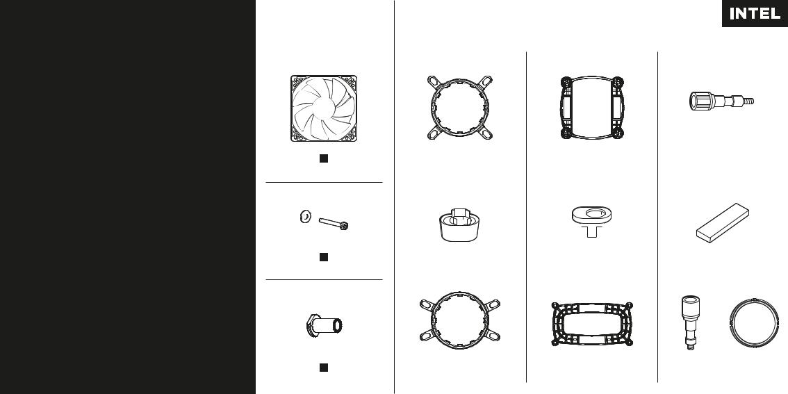
Included Hardware
Matériel inclus • Mitgelieferte Montageteile • Hardware incluso Hardware incluido • Включено
следующее оборудование
A
FAN
E
x4
I
x4
Highlighted parts for Intel installation only • Les sections en surbrillance concernent uniquement l'installation Intel • Die markierten Passagen beziehen sich nur auf die Intel • Parti evidenziate solo per l'installazione di Intel • Componentes de instalación solamente para Intel • Части, выделенные цветом, только для установки Intel
|
|
B |
|
|
|
|
|
|
C |
|
|
|
|
|
|
|
D |
|
|
INTEL 115x/1366 |
|
INTEL 115x/1366 |
|
x4 • INTEL 1155/1156/1366 |
|||||||||||||||
|
|
|
|
|
|
|
|
|
|
|
|
|
|
|
|
& AMD AM2/AM3 |
|||
|
|
|
|
|
|
|
|
|
|
|
|
|
|
|
|
|
|
|
|
|
|
|
|
|
|
|
|
|
|
|
|
|
|
|
|
|
|
|
|
|
|
|
|
|
|
|
|
|
|
|
|
|
|
|
|
|
|
|
|
|
|
|
|
|
|
|
|
|
|
|
|
|
|
|
|
|
|
|
|
|
|
|
|
|
|
|
|
|
|
|
|
|
|
|
|
|
|
|
|
|
F |
|
|
|
G |
|
|
|
||
H |
|
|||||||||
|
x4 |
|
|
x4 |
|
|||||
|
|
|
x2 |
|
||||||
|
|
|
|
|
|
|
|
|
|
|
|
|
|
|
|
|
|
|
|
|
|
|
|
|
|
|
|
|
|
|
|
|
|
|
|
|
|
|
|
|
|
|
|
|
|
|
|
|
J |
|
K |
|
L |
|
|
|
M |
AMD AM2/AM3 |
|
AMD AM2/AM3 |
x4 • INTEL LGA 2011 |
|
x1 |
|||
|
|
|
|
|
|
|
|
|
|
|
|
|
|
|
|
|
|

|
|
|
|
|
|
|
|
|
|
|
|
|
|
|
|
|
|
|
|
|
|
|
|
|
|
|
|
|
|
|
|
|
|
|
|
1 |
Prepare Retention Ring for Installation |
2 |
Assemble and Install Intel Backplate |
|||||
|
|
|
|
|
||||
|
|
|
Préparez l'anneau de retenue pour l'installation • Halterungsring für die Installation präparieren • |
|
Assemblez et installez la plaque arrière Intel • Intel-Rückwand zusammenbauen und montieren • |
|||
|
|
|
Preparare l'anello di sicurezza per l'installazione • Prepare la anilla de sujeción para |
|
Assemblare e installare la piastra posteriore Intel • Ensamble e instale la placa de soporte Intel • |
|||
|
|
|
su instalación • Подготовьте крепежное кольцо к установке |
|
Соберите и установите опорную пластину Intel |
|||
Fig. A
Intel 1366/2011
Fig. B
Intel 1155/1156
Assemble the retention ring. For Intel 1366/2011 Socket Follow Fig (A). For Intel 1155/1156 Socket follow Fig (B)
Installez l'anneau de retenue Pour une fiche Intel 1366/2011, suivez la Figure A. Pour une fiche Intel 1155/1156, suivez la Figure B.
1366 775
|
66 |
3 |
|
1 |
|
7
7 5
Bauen Sie den Halterungsring zusammen (s. Abbildung |
5 |
|
|
6 |
11 |
A für Socket Intel 1366/2011 oder Abbildung B für Socket |
|
|
|
|
|
Intel 1155/1156). |
1156 |
|
|
|
|
Assemblare l'anello di sicurezza. Socket Intel 1366/2011:
seguire la figura A. Socket Intel 1155/1156: seguire H la figura B.
Monte la anilla de sujeción. Para zócalos Intel 1366/2011, |
Fig. A |
|
|
siga la Figura A. Para zócalos Intel 1155/1156, siga la |
|
Figura B. |
|
Соберите крепежное кольцо. Для процессорного гнезда |
|
Intel 1366/2011 следуйте Рисунку A. Для процессорного |
|
гнезда Intel 1155/1156 следуйте Рисунку B. |
I |
G |
INTEL |
D
B
F |
L |
|
INTEL 2011 |
||
|
Fig. B
Insert the pins (I) into the appropriate location
(LGA 1155/1156/1366) marked on the backplate. Install and remove the adhesive backing (Figure A). Install the assembled backplate (Figure B).
Note: Intel LGA 2011 does not require a backplate
Insérez les broches (I) dans l'emplacement approprié (LGA 1155/1156/1366) marqué sur la plaque arrière. Installez et retirez la protection adhésive (Figure A). Installez la plaque arrière assemblée (Figure B).
Remarque : Intel LGA 2011 ne nécessite aucune plaque arrière
Befestigen Sie die Stifte (I) an der auf der Rückwand markierten Stelle (LGA 1155/1156/1366). Bringen Sie die Klebefläche an und ziehen Sie den Schutzfilm ab (Abbildung A). Montieren Sie die zusammengebaute Rückwand (Abbildung B).
Hinweis: Der Intel LGA 2011 erfordert keine Rückwand
Inserire i pin (I) nella posizione appropriata
(LGA 1155/1156/1366), indicata sulla piastra posteriore. Installare e rimuovere lo strato adesivo (figura A). Installare la piastra posteriore assemblata (figura B).
Nota: Intel LGA 2011 non necessita di una piastra posteriore
Introduzca las patillas (I) en el lugar adecuado (LGA 1155/1156/1366) marcado en la placa de soporte. Realice la instalación y retire la cubierta del adhesivo (Figura A). Instale la placa de soporte ensamblada (Figura B).
Nota: Los zócalos Intel LGA 2011 no requieren placa de soporte
Вставьте контакты (I) в соответствующее положение (LGA 1155/1156/1366), отмеченное на опорной пластине. Установите и удалите клейкое покрытие (рисунок A). Установите собранную опорную пластину (рисунок B).
Примечание. Для Intel LGA 2011 опорная пластина не требуется.
 Loading...