


INSTALLATION AND OPERATION MANUAL
MINI INDUSTRIAL OUTDOOR 802.11A/N WIRELESS ETHERNET
This manual serves the following ComNet Model Numbers:
NW1/M
NW2/M
NWK1/M
NWK2/M
Thank you for purchasing NetWave® from ComNet. This installation guide applies to the following models:
NW1/M: Industrial Multipoint, FCC Version, User Configurable NW2/M: Industrial Multipoint, ETSI Version, User Configurable
NWK1/M: Industrial Multipoint Kit, FCC Version (Includes NWK1/M_AP and NWK1/M_CL)
NWK2/M: Industrial Multipoint Kit, ETSI Version (Includes NWK2/M_AP and NWK2/M_CL)
The NetWave industrially hardened wireless Ethernet transmission link from ComNet can be configured through the embedded User Interface as a Client or as an Access Point. This point-to-multipoint model allows multiple Ethernet endpoints to be connected to a central Access Point. Up to 15 endpoints can be linked to a central access point. The NW1/M and NW2/M support up to 95Mbps throughput using MIMO technology. An easy to read LED array displays unit operational status along with received signal strength ensuring optimal installation and operation. The units are passive powered by PoE (Power over Ethernet) through a supplied PoE injection module. The NW1/M is FCC certified and the NW2/M is ETSI, DFS and TPC certified.
INSTALLATION AND OPERATION MANUAL |
NW(1,2)/M |
|
|
About This Guide
This guide is intended for different users such as engineers, integrators, developers, IT managers, and technicians.
It assumes that users have some PC competence and are familiar with Microsoft Windows operating systems and web browsers such as Windows Internet Explorer and Mozilla Firefox, as well as have knowledge of the following:
»»Installation of electronic equipment »»Electrical regulations and guidelines
»»Knowledge of Local Area Network technology
Related Documentation
The following documentation is also available:
»»NW(1,2)/M Datasheet
»»NW(1,2)/M Quick Start Guideº
»»NWK(1,2)/M Datasheet
»»NWK(1,2)/M Quick Start Guideº
Website
For information on ComNet’s entire product line, please visit the ComNet website at http://www.comnet.net
Support
For any questions or technical assistance, please contact your sales person (sales@comnet.net) or the customer service support center (techsupport@comnet.net)
Safety
»»Only ComNet service personnel can service the equipment. Please contact ComNet Technical Support.
»»The equipment should be installed in locations with controlled access, or other means of security, and controlled by persons of authority.
TECH SUPPORT: 1.888.678.9427
INS_NW(1,2)/M_REV– 06/10/13 PAGE 2
INSTALLATION AND OPERATION MANUAL |
NW(1,2)/M |
|
|
Contents
About This Guide |
2 |
Related Documentation |
2 |
Website |
2 |
Safety |
2 |
Overview |
6 |
Legal Information |
6 |
1.0 Introduction |
7 |
1.1 System Requirements |
7 |
2.0 Point to Multi-Point |
8 |
3.0 Point-to-Point Topology Utilizing Dual Ports |
8 |
4.0 Cabling Requirements |
9 |
5.0 Hardware Installation |
9 |
5.1 Outdoor Ethernet Gland Installation |
9 |
5.2 NW1/M and NW2/M Indicating LED Details |
11 |
5.3 Outdoor Standard Mounting Hardware |
11 |
5.4 Outdoor Upgrade Mounting Hardware |
12 |
6.0 Key Default Configurations |
13 |
7.0 Quick Configuration |
14 |
Detailed Configuration |
15 |
8.0 Getting Started |
15 |
8.1 Operating Modes |
16 |
8.2 Buttons and Alerts |
16 |
9.0 Status Tab |
18 |
9.1 Overview |
18 |
9.2 Wireless |
19 |
9.3 Wireless (for AP Mode) |
19 |
9.4 Wireless (for Station Mode) |
20 |
9.5 Associated Stations (for AP Mode) |
21 |
9.6 System |
21 |
9.7 Memory |
21 |
TECH SUPPORT: 1.888.678.9427
INS_NW(1,2)/M_REV– 06/10/13 PAGE 3
INSTALLATION AND OPERATION MANUAL |
|
NW(1,2)/M |
||
|
|
|
|
|
|
9.8 Network |
22 |
||
|
9.9 DHCP Leases |
22 |
||
|
9.10 Link Status (for Station Mode) |
22 |
||
|
9.11 Routes |
23 |
|
|
|
9.12 Kernel Log |
24 |
|
|
|
9.13 Real-time Graphs |
25 |
|
|
10.0 System Tab |
28 |
|
||
|
10.1 |
System Properties |
28 |
|
|
10.2 Time Synchronization |
29 |
|
|
|
10.3 Administration |
30 |
|
|
|
10.4 Services |
32 |
|
|
|
10.5 SNMP |
33 |
|
|
|
10.6 Reset Button |
34 |
|
|
|
10.7 Indicating LEDs |
35 |
|
|
|
10.8 Backup/Flash Firmware |
36 |
|
|
|
10.9 Reboot |
36 |
|
|
11.0 Network Tab |
37 |
|
||
|
11.1 Interfaces – WAN |
38 |
|
|
11.2 |
Interfaces – LAN |
41 |
|
|
11.3 |
WiFi – Overview |
44 |
|
|
11.4 |
WiFi – Wireless Network |
48 |
|
|
11.5 |
Hostnames |
58 |
|
|
11.6 |
Static Routes |
58 |
|
|
|
11.7 Firewall |
59 |
|
|
11.8 |
Diagnostics |
61 |
|
|
|
11.9 Quality of Service |
62 |
|
|
12.0 AP Controller Tab |
63 |
|
||
|
12.1 Getting Started with Managing APs using the APc |
63 |
|
|
|
12.2 L2TPv3 Settings |
63 |
|
|
|
12.3 IPSec |
64 |
|
|
|
12.4 APc SNMP Settings |
64 |
|
|
|
12.5 AP SNMP Settings |
64 |
|
|
TECH SUPPORT: 1.888.678.9427
INS_NW(1,2)/M_REV– 06/10/13 PAGE 4
INSTALLATION AND OPERATION MANUAL |
|
NW(1,2)/M |
|
|
|
|
|
|
13.0 Troubleshooting |
65 |
|
|
13.1 Troubleshooting steps |
65 |
|
|
13.2 Resetting to factory default |
65 |
|
|
14.0 Glossary |
66 |
|
|
15.0 Agency Compliance |
69 |
|
|
16.0 GPL (General Public License) Statement |
71 |
|
TECH SUPPORT: 1.888.678.9427
INS_NW(1,2)/M_REV– 06/10/13 PAGE 5
INSTALLATION AND OPERATION MANUAL |
NW(1,2)/M |
|
|
Overview
Legal Information
No part of this document may be reproduced or transmitted in any form or by any means, electronic and mechanical, for any purpose, without the express written permission of ComNet.
Copyright
Copyright © 2015 Communication Networks, LLC (dba ComNet). All rights reserved.
Disclaimer
ComNet reserves the right to make changes in specifications at any time without notice. The information furnished by ComNet in this material is believed to be accurate and reliable. However, ComNet assumes no responsibility for its use.
TECH SUPPORT: 1.888.678.9427
INS_NW(1,2)/M_REV– 06/10/13 PAGE 6
INSTALLATION AND OPERATION MANUAL |
NW(1,2)/M |
|
|
1.0 Introduction
The NetWave® industrially hardened wireless Ethernet transmission link from ComNet can be configured through the embedded User Interface as a Client or as an Access Point. This point-to- multipoint model allows multiple Ethernet endpoints to be connected to a central Access Point. Up to 15 endpoints can be linked to a central access point. The NW1/M and NW2/M support up to 95Mbps throughput using MIMO technology. An easy to read LED array displays unit operational status along with received signal strength ensuring optimal installation and operation. The units can be powered by an IEEE 802.3af PoE compliant switch or through the supplied power injection module. The NW1/M is FCC certified and the NW2/M is ETSI, DFS and TPC certified.
This user manual is a guide for the NetWave NW(1,2)/M wireless Ethernet device as well as the NWK(,2)/M preconfigured kits. ComNet NetWave Wireless offers OpenWRT with the most
advanced Qualcomm Atheros 10.1.x wireless drivers. NetWave now includes a new user-friendly LuCI web interface for configuring the device. OpenWRT is an extensible GNU/Linux distribution for embedded devices. It is built from the ground up to be a full-featured, easily modifiable operating system. It is powered by a Linux kernel that's more recent than most other distributions. LuCI is a free, clean, extensible and easily maintainable web user interface for embedded devices. It has high performance, small installation size, fast runtimes, and good maintainability. The units come configured for either point to point or point to multipoint applications.
This manual contains detailed operational and configuration information not covered in the quick start guides.
This guide applies to the following models:
NW1/M - Industrial Multipoint, FCC Version, User Configurable
NW2/M - Industrial Multipoint, ETSI Version, User Configurable
NWK1/M - Industrial Multipoint Kit, FCC Version (Includes NWK1/M_AP and NWK1/M_CL)
NWK2/M - Industrial Multipoint Kit, ETSI Version (Includes NWK2/M_AP and NWK2/M_CL)
1.1 System Requirements
Operating System:
Microsoft Windows XP, Windows Vista, Windows 7, Windows 8, Linux, or Mac OS X.
Web Browser:
Mozilla Firefox, Google Chrome, Apple Safari, or Microsoft Internet Explorer 8 or above.
TECH SUPPORT: 1.888.678.9427
INS_NW(1,2)/M_REV– 06/10/13 PAGE 7
INSTALLATION AND OPERATION MANUAL |
NW(1,2)/M |
|
|
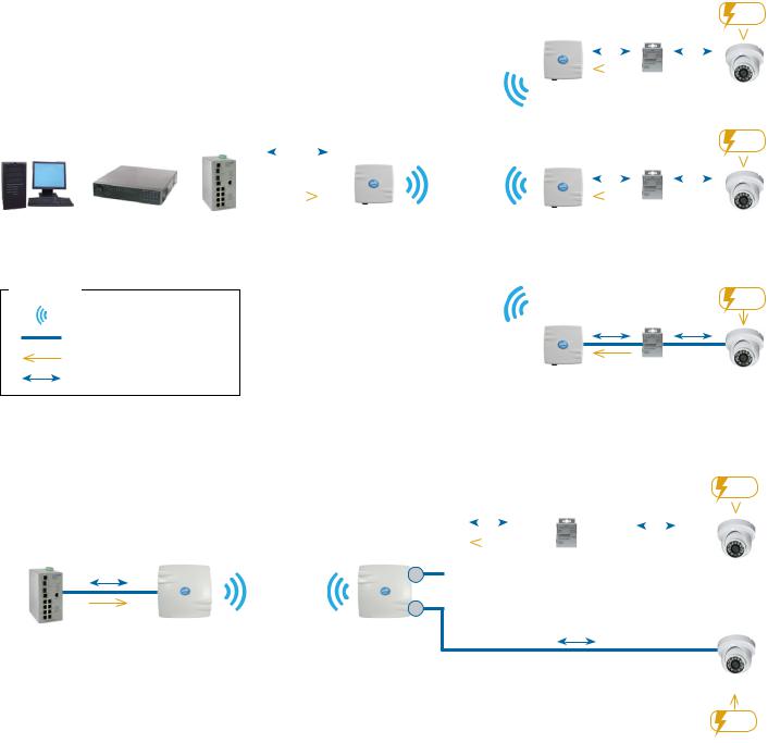
2.0 Point to Multi-Point
These individual units allow the user to configure for either multipoint access point or client operation. There is a MAC address lock feature that can be enabled through the user interface but is not enabled by default. The NW(1,2)/M includes a 16dBi 30° internal antenna and there is an optional 8dBi 70° internal antenna. See the ComNet website for the latest information regarding antenna support.
Preconfigured NWK kits do not support point-to-multipoint topologies.
|
|
|
|
|
|
|
|
|
|
|
|
|
PIM or other |
|
Power |
|||
|
|
|
|
|
|
|
|
NW1/M (Client) |
PSE device |
|
|
|
||||||
|
|
|
|
|
|
|
|
|
|
|
||||||||
|
|
|
|
|
|
|
|
|
|
Ethernet |
Ethernet |
|
|
|
||||
|
|
|
|
|
|
|
|
|
|
|
|
|
||||||
|
|
|
|
|
|
|
|
|
|
|
|
|
|
|
|
|
|
|
|
|
|
|
|
|
|
|
|
|
|
|
|
|
|
|
|
|
|
|
|
|
|
|
|
|
|
|
|
|
|
|
|
|
|
|
|
|
|
|
|
|
|
|
|
|
|
|
|
PoE |
|
|
|
IP Camera |
|||
|
|
|
|
|
|
|
|
|
|
|
|
|
|
|
|
|||
|
|
|
|
|
|
|
|
|
|
|
|
|
PIM or other |
|
Power |
|||
|
|
|
|
|
|
|
|
NW1/M (Client) |
PSE device |
|
|
|
||||||
|
|
10/100 Ethernet |
|
|
|
|
||||||||||||
|
|
|
|
|
Ethernet |
Ethernet |
|
|
|
|||||||||
|
|
|
|
|
|
|
|
|||||||||||
|
|
|
|
|
|
|
|
|
|
|
|
|
|
|
|
|
|
|
|
|
|
|
|
|
|
|
|
|
|
|
|
|
|
|
|
|
|
|
|
|
|
|
|
|
|
|
|
|
|
|
|
|
|
|
|
|
|
|
|
|
PoE |
|
|
|
|
PoE |
|
|
|
IP Camera |
|||||
|
|
|
|
|
|
|
|
|
|
|
|
|
||||||
PC |
NVR |
ComNet Gigabit |
NW1/M/IA870 |
|
|
|
||||||||||||
|
|
|
|
|
|
|||||||||||||
|
|
Managed Switch |
(Recommended |
|
|
|
|
|
|
|||||||||
|
|
with 30W PoE+ |
Access Point) |
|
|
|
|
|
|
|||||||||
LEGEND |
|
PIM or other |
Power |
|
|
||
WIRELESS |
NW1/M (Client) |
PSE device |
|
Ethernet |
Ethernet |
|
|
CAT5 |
|
||
|
|
|
|
POWER |
PoE |
|
|
|
|
|
|
ETHERNET DATA |
|
|
|
3.0 Point-to-Point Topology Utilizing Dual Ports
NW1/M
10/100 Mbps (Access Point)
Ethernet
PoE
ComNet Managed
Switch with 30W PoE
Connected to Network
|
|
|
|
|
|
|
PIM or other |
|
|
|
Power |
||
|
|
|
|
|
|
|
PSE device |
|
|
|
|
|
|
|
|
|
|
|
|
|
|||||||
NW1 |
|
|
|
Ethernet |
Ethernet |
|
|
||||||
|
|||||||||||||
|
|
|
|
|
|
|
|
|
|
|
|
|
|
|
|
|
|
|
|
|
|
|
|
|
|
|
|
|
|
|
|
|
|
|
|
|
|
|
|
|
|
(Client) |
|
|
|
|
PoE |
|
|
|
|
|
|
||
|
P1 |
|
|
|
|
|
|
|
|
IP Camera |
|||
|
|
||||||||||||
P2
Ethernet
IP Camera
Power
TECH SUPPORT: 1.888.678.9427
INS_NW(1,2)/M_REV– 06/10/13 PAGE 8
INSTALLATION AND OPERATION MANUAL |
NW(1,2)/M |
|
|
4.0 Cabling Requirements
Shielded CAT 5 or better should be used for all out of plant Ethernet connection and should be properly grounded through the PoE AC ground. Industrial grade shielded Ethernet cable is recommended to help prevent ESD damage commonly experienced with outdoor installations. Visit www.comnet.net/comnet-products/cables
5.0Hardware Installation
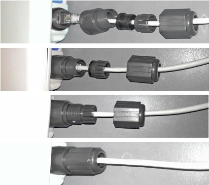
5.1Outdoor Ethernet Gland Installation
There will be at least one cable gland included with each outdoor enclosure. Below is an image of the individual parts of the gland with an Ethernet cable routed through.
Note: The split rubber washer allows a pre-terminated Ethernet cable to be used.
Once the cable has been routed through the weather connection, and the RJ45 connection has been made, screw in the gland into the housing making sure it is tight enough for a water tight seal. Push the split rubber gasket into place and loosely screw the cap that goes over the rubber washer.
Once the gland is tight in the housing, tighten the outer nut/cap making sure the rubber seal squeezes and seals the Ethernet cable to the gland as shown below.
TECH SUPPORT: 1.888.678.9427
INS_NW(1,2)/M_REV– 06/10/13 PAGE 9
INSTALLATION AND OPERATION MANUAL |
NW(1,2)/M |
|
|
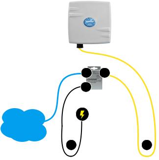
Connect one end of an RJ-45 Ethernet cable to the LAN OUT port of the Power Injection Module (PIM) and the other end to LAN of the access point – as sown below.
Note: Maximum length of the RJ-45 CAT5 cable is 90 meters.
Connect the RJ-45 Ethernet cable attached to the PIM to a network device, such as a switch or to the configuration PC. Then plug the power adaptor to an AC power outlet and power plug into the socket of the PIM – as shown in the diagram below.
Note: DC Passive PoE input for the NW(1,2)/M and NWK(1,2)/M is 48 VDC.
Ethernet
Network
A.Connect one end of an RJ-45 Ethernet cable to the OUT port of the Power Injection Module (PIM) and the other end to LAN of the access point.
Maximum length of the RJ-45 CAT5 cable is 100 meters.*
B.Connect the RJ-45 Ethernet cable attached to the PIM to a network device, such as to a switch or to the PC you will use to configure the access point.
B |
A |
C. Connect the power adaptor to the main electrical supply |
|
|
and the power plug into the socket of the PIM. |
C
PoE power input: Passive PoE (range 42 to 56 VDC).
The unit can also be powered by a suitable IEEE 802.3af/at PSE device such as a PoE switch or injector.
D.A Drip Loop is recommended as additional precaution against moisture entering the Access Point housing.
D |
D |
* Up to 200mW radio. For higher power radio upgrade to higher rating |
power adapter. |
TECH SUPPORT: 1.888.678.9427
INS_NW(1,2)/M_REV– 06/10/13 PAGE 10

INSTALLATION AND OPERATION MANUAL |
|
NW(1,2)/M |
|||||||||
|
|
|
|
|
|
|
|
||||
5.2 NW1/M and NW2/M Indicating LED Details |
|||||||||||
|
|
|
|
|
|
|
|
|
|
|
|
RSSI1 |
RSSI2 |
RSSI3 |
RSSI4 |
LED |
VISUAL CUE |
INDICATION |
|||||
|
|
|
|||||||||
POWER |
SOLID GREEN |
Power is supplied to the unit |
|||||||||
|
|
|
|
|
|
|
|
||||
|
|
|
|
|
|
|
|
OFF |
No power is supplied to the unit or the unit is in reset. |
||
|
|
|
|
|
|
|
|
|
|||
|
|
|
|
|
|
|
|
|
|
|
|
|
|
|
|
|
|
|
|
LAN |
SOLID GREEN |
LAN Connected |
|
|
|
|
|
|
|
|
|
||||
|
|
|
|
|
|
|
|
|
|
||
|
|
|
|
|
|
|
|
OFF |
No Connectivity |
||
|
|
|
|
|
|
|
|
|
|||
|
|
|
|
|
|
|
|
|
|
|
|
|
|
|
|
|
|
|
|
RSSI1 |
SOLID RED |
Weak Connection |
|
|
|
|
|
|
|
|
|
|
|
|
|
|
|
|
|
|
|
|
|
RSSI2 |
SOLID ORANGE |
Moderate Connection |
|
|
|
|
|
|
|
|
|
||||
|
|
|
|
|
|
|
|
|
|
|
|
|
|
|
|
|
|
|
|
RSSI3 |
SOLID GREEN |
Solid Connection |
|
POWER |
LAN |
|
|
|
|
||||||
|
|
|
|
|
|
|
|||||
|
|
|
|
RSSI4 |
SOLID GREEN |
Excellent Connection |
|||||
|
|
|
|
|
|
|
|
||||
|
|
|
|
|
|
|
|
(Advisable to check Status Page to confirm RSSI is > -55) |
|||
|
|
|
|
|
|
|
|
|
|
||
SIGNAL STRENGTH: |
|
|
|
|
|
||||||
|
|
|
|
|
|||||||
WEAK SIGNAL |
EXCELLENT SIGNAL |
5.3 Outdoor Standard Mounting Hardware
This mounting hardware will support pole diameters up to 2 in (5.8 cm). Below are the parts contained in the standard mounting hardware.
Here is the mounting hardware assembled shown in a +30° and -30°vertical position
TECH SUPPORT: 1.888.678.9427
INS_NW(1,2)/M_REV– 06/10/13 PAGE 11
INSTALLATION AND OPERATION MANUAL |
NW(1,2)/M |
|
|
6.0 Key Default Configurations
IP Address of Web Server |
192.168.10.100 (NWKX_AP) |
|
192.168.10.101 for all others |
LAN Mode for Web Server |
Static Addressing |
Web Server User ID |
admin |
Web Server Password |
admin |
SSID |
NetWave-1 |
WPA Pre-shared Key |
12345678 |
Channel-Frequency (AP) |
Auto |
Channel Spectrum Width |
20/40M |
Long Range Parameters |
Enabled and defaulted to 1000m |
Note: A Reset to defaults (performed on the ADMIN page or via the RESET button) will erase all user configurations.
TECH SUPPORT: 1.888.678.9427
INS_NW(1,2)/M_REV– 06/10/13 PAGE 12
INSTALLATION AND OPERATION MANUAL |
NW(1,2)/M |
|
|
7.0 Quick Configuration
1.Connect an Ethernet cable from the port labelled as IN on the power Injection Module to either a laptop or a PC LAN port.
2.Connect the second Ethernet cable from the OUT port on the Power Injection Module to the NetWave LAN port.
3.Apply 48 VDC to the Power Injection Module with the provided power supply. You should notice the green LED illuminate in the Power Injection Module and the power LED on the NetWave unit.
4.Set the IP address of the laptop being used to configure NetWave to static and the subnet to 192.168.10.x/24 subnet.
5.Point the browser to 192.168.10.101. This is the default address.
For preconfigured kits (NWKX_AP and NWKX_CL) point the Browser to 192.168.10.100 for the Access Point or 192.168.10.101 for the Client.
6.A login prompt will pop up. Enter:
Username admin
Password admin
7.Select the NETWORK » WIFI tab and set the desired network settings. Select Apply & Save
Note: This will be the network address for the NetWave web server. It is not necessary to set to the same subnet as the operating network but it is recommended.
8.Select the NETWORK -> WIFI tab and set:
•Wireless mode – Set to AP or Client
•Country code – Only required if setting up the NW2/M (ETSI) model
Note: It is the user’s responsibility to ensure that the correct country is chosen. ComNet accepts no liability for incorrect equipment set up.
•Output RF power – if received signal strength is greater than -40 dBm, it is recommended to reduce RF TX power
•Set SSID – if changing from the default setting
•Channel Spectrum Width – May want to reduce to 20M from the default 20/40M if the 5GHz spectrum is crowded
•Wireless Security – if changing from default settings
•Select Apply Settings
•Select Save
Note: NW1/M and NW2/M Multipoint nodes will need to have the Wireless Mode set to either AP or Client (default is Client). And the IP addresses will need to be all set to different addresses (default address is 192.168.10.101). Once this is done, all the clients will connect to the multipoint AP with all other setting kept at default.
TECH SUPPORT: 1.888.678.9427
INS_NW(1,2)/M_REV– 06/10/13 PAGE 13
INSTALLATION AND OPERATION MANUAL |
NW(1,2)/M |
|
|
TECH SUPPORT: 1.888.678.9427
INS_NW(1,2)/M_REV– 06/10/13 PAGE 14
INSTALLATION AND OPERATION MANUAL |
NW(1,2)/M |
|
|
Detailed Configuration
8.0 Getting Started
To access the NetWave configuration interface, perform the following steps:
1.Connect the local area network (LAN) port of the router to the network port of your computer using an Ethernet cable. Ethernet cables are also known as LAN cables or network cables. They connect devices such as computers, routers, and switches on wired networks.
2.Next, take the power adapter that comes with the set and connect it to a power socket as well as the router. Turn on the power.
3.Assign the Ethernet adapter on your computer with a static IP address on the 192.168.1.x network, e.g. 192.168.10.10 and with a subnet mask 255.255.255.0.
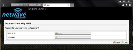
4.Launch a web browser and enter the default IP address of the router, 192.168.10.101, into the address bar.
The first page that you see is the login page. The words on the top left denote the hardware part number and the firmware build version e.g. NW1 NW1_v1.78.0
The login page is presented upon requesting the Netwave Radio’s IP address.
The default authorization details are:
Username: admin
Password: admin
TECH SUPPORT: 1.888.678.9427
INS_NW(1,2)/M_REV– 06/10/13 PAGE 15
INSTALLATION AND OPERATION MANUAL |
NW(1,2)/M |
|
|
8.1 Operating Modes
The Netwave Radio can operate in the following modes:
1.Access Point WDS
2.Station (Client) WDS
In a commonly used setup, the WAN port of an access point connects to a modem via an Ethernet cable. A modem can be a cable, digital subscriber line (DSL), or fiber optic modem. A modem translates the signal from the internet service provider (ISP) to Ethernet signals that the access point can understand. This allows the access point to have internet connection.
Other devices called stations connect wirelessly to this access point. These devices can be mobile phones, printers, IP cameras, laptops, or even other routers. The stations obtain internet connection from the access point.
An access point WDS and a station WDS together extend the wireless coverage, like a repeater.
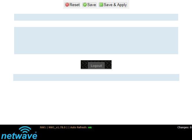
8.2 Buttons and Alerts
The buttons are described here.
Reset |
Undo the changes. |
Save |
Saves the changes but does not take effect till settings are applied |
Save & Apply |
Saves and applies the changes. |
|
Please use this button instead of the 'Save' button so that the |
|
changes would be applied immediately. |
|
It is recommended to click this button before moving to a different |
|
page. |
Logout |
Logs out of the router's web page. |
Note: At the top right corner of the NetWave configuration web page, there may be either of the following texts displayed:
Changes: 0: Means that all changes on the configuration web page have been applied to the Wireless Device.
Unsaved Changes: Shows the number of changes that have not yet been Save & Apply.
TECH SUPPORT: 1.888.678.9427
INS_NW(1,2)/M_REV– 06/10/13 PAGE 16
INSTALLATION AND OPERATION MANUAL |
NW(1,2)/M |
|
|
8.2.1 Reset Button
 The reset button is a physical hardware button on the board.
Please refer to Section "Reset Button."
8.2.2 Indicating LEDs
The light emitting diodes (LEDs) on the board are described in Section "LEDs on the Board".
8.2.3 Buzzer
The new NetWave buzzer makes the following sounds:
•Power up: Beep once.
•End of Firmware Loading: Beep twice.
•Alignment: Beep according to signal thresholds defined. The alignment buzzer is described in Section "Link Status (for Station Mode)".
TECH SUPPORT: 1.888.678.9427
INS_NW(1,2)/M_REV– 06/10/13 PAGE 17
INSTALLATION AND OPERATION MANUAL |
NW(1,2)/M |
|
|
9.0 Status Tab
After login, when you click on the Status top-level tab, you can see the second-level tabs of Overview, Routes, System Log, Kernel Log, and Real-time Graphs. This is shown in Figure 2.
Figure 2: The Status Tab.
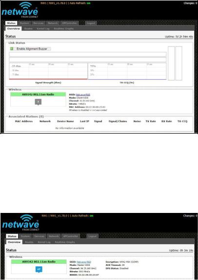
9.1 Overview
The Status » Overview page is divided into the sections Wireless, Associated Stations, System, Memory, Network, and DHCP Leases.
Uptime: Displays the duration of time since the router was turned on or rebooted.
Figure 3: The Status » Overview page.
TECH SUPPORT: 1.888.678.9427
INS_NW(1,2)/M_REV– 06/10/13 PAGE 18
INSTALLATION AND OPERATION MANUAL |
NW(1,2)/M |
|
|
9.2 Wireless
The wireless chipset model is shown in the little box on the left e.g. AR9342 802.11an Radio.
Figure 4: Wireless chipset model.
The characters AP in the small callout box means that the radio is operating in the Access Point (AP) mode. If the characters are CPE, it means that the radio is operating as a customer-premises equipment (CPE) i.e. a station. The character X is shown if the radio is disabled.
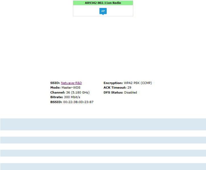
9.3 Wireless (for AP Mode)
The Wireless section in the Status » Overview page shows a summary of the wireless parameters. The following describes the parameters when the device is in the AP mode.
Figure 5: A summary in the Wireless section for a device operating as an 802.11 access point.
SSID |
Displays the name of the wireless network that this access point (AP) is offering, the Service |
|
Set Identifier (SSID). |
Mode |
This is 'Master' if the device is in AP WDS mode. |
Channel |
Shows the channel number and frequency that this AP is using. |
Bitrate |
This is the maximum bitrate supported by the radio in the current configuration. |
BSSID |
This is the MAC address of the AP's radio. |
Encryption |
Displays the wireless encryption used. |
ACK Timeout |
Shows the maximum acknowledgment time in microseconds. |
DFS Status |
If DFS is enabled, the AP automatically switches channel if radar is detected on the current |
|
channel. |
TECH SUPPORT: 1.888.678.9427
INS_NW(1,2)/M_REV– 06/10/13 PAGE 19
INSTALLATION AND OPERATION MANUAL |
NW(1,2)/M |
|
|
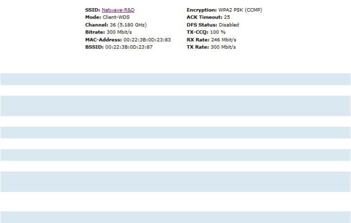
9.4 Wireless (for Station Mode)
The following describes the parameters for a device operating in Station mode.
Figure 6: A summary in the Wireless section for a device operating as an 802.11 station.
SSID |
Displays the name of the wireless network that this station should be associated with. |
Mode |
This is 'Client' if the device is in Station WDS mode. |
Channel |
Shows the channel number and frequency that this station is using. Normally, it would |
|
automatically select the same channel as the AP. |
Bitrate |
This is the maximum bitrate supported by the radio in the current configuration. |
MAC-Address |
States the MAC address of the device's radio. |
BSSID |
This is the MAC address of the AP's radio. |
Encryption |
Displays the wireless encryption used. |
ACK Timeout |
Shows the maximum acknowledgment time in microseconds. |
DFS Status |
If DFS is enabled, the AP automatically switches channel if radar is detected on the |
|
current channel. |
TX-CCQ |
Displays the transmission quality in %. A higher percentage means a better wireless |
|
connection quality. |
RX Rate |
Shows the receive bit rate of this station. |
TX Rate |
Shows the transmit bit rate of this station. |
TECH SUPPORT: 1.888.678.9427
INS_NW(1,2)/M_REV– 06/10/13 PAGE 20
INSTALLATION AND OPERATION MANUAL |
NW(1,2)/M |
|
|
9.5 Associated Stations (for AP Mode)
This section shows the connected devices, if the Radio is in the AP mode.
Figure 7: List of Associated Stations.
If there are no associated stations, the text “No information available” is displayed. The parameters shown are as follows:
MAC-Address |
Displays the MAC address of the station's radio. |
Network |
States the name of the wireless network. |
Device Name |
Shows the name of the station. |
Last IP |
States the most recent IP address of the station as seen by the Radio. |
Signal |
Displays the received signal strength from the station e.g. -31 dBm. |
Signal/Chains |
Shows the received signal strengths from the station on each antenna e.g. -52, -35, -34 dBm. |
|
The value of -95 dBm is taken to mean “no antenna” if the radio has only 2 antennas. |
Noise |
Displays the received noise power at the AP. |
TX Rate |
Shows the transmit bit rate from the AP towards this station. |
RX Rate |
Shows the receive bit rate at the AP from this station. |
TX-CCQ |
Indicates the wireless connection quality. |
9.6 System
This section shows the Router Name, Router Model,
Firmware Version, Kernel Version, and Local Time.
Figure 8: System parameters.
9.7 Memory
Here, the Total Available and Free memory are shown.
Figure 9: Total Available and Free Memory.
TECH SUPPORT: 1.888.678.9427
INS_NW(1,2)/M_REV– 06/10/13 PAGE 21
INSTALLATION AND OPERATION MANUAL |
NW(1,2)/M |
|
|
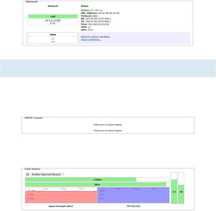
9.8 Network
This section displays the status of the LAN and WAN networks.
|
Figure 10: Network summary. |
Status: |
Shows summaries of the interfaces for the LAN and WAN zones. This may include uptime, MAC |
|
address, protocol, bytes and packets received by the device, bytes and packets transmitted by |
|
the device, and its IPv4 address. |
9.9 DHCP Leases
This section shows a table of MAC and IP addresses of connected computers with static DHCP leases. They are specified in the Network » Interfaces » LAN » Static Leases section of the device's configuration web page.
Figure 11: Currently active static DHCP leases.
9.10 Link Status (for Station Mode)
This section only applies if the device operates as an 802.11 station.
Figure 12: The Link Status section.
In the Link Status section on the Status » Overview web page, the value in the top left box denotes the current received signal strength e.g. -48 dBm. The box directly below it shows the current TX-CCQ (transmission client connection quality) e.g. 71 %. The bottom left box shows a real-time graph of the received signal strength over the last 60 seconds.
TECH SUPPORT: 1.888.678.9427
INS_NW(1,2)/M_REV– 06/10/13 PAGE 22
 Loading...