


INSTALLATION AND OPERATION MANUAL
CWGE9MS
COMMERCIAL GRADE 9 PORT GIGABIT MANAGED ETHERNET SWITCH
WITH (7) 10/100/1000TX + (2) 1000FX SFP
OR 10/100/1000TX PORTS
V1.02 – October 2010
The ComNet™ CWGE9MS Managed Ethernet Switch provides transmission of (7) 10/100/1000 BASE-TX and
(2) 1000FXcombo ports. These units are available for use with either conventional CAT-5e copper or optical transmission media. Ports 1 – 7 support the 10/100/1000 Mbps Ethernet IEEE 802.3 protocol, and auto-negotiating and auto-MDI/MDIX features are provided for simplicity and ease of installation. Ports 8 – 9 are 10/100/1000 configurable for copper or 1000 fiber media for use with multimode or single mode optical fiber without need for configuration, selected by optional SFP modules. These network managed layer 2 switches are optically and electrically compatible with any IEEE 802.3 compliant Ethernet devices. Plug-and-play design ensures ease of installation, and no electrical or optical adjustments are ever required. The CWGE9MS incorporates LED indicators for monitoring the operating status of the managed switch and network.
FCC Warning
This Equipment has been tested and found to comply with the limits for a Class-A digital device, pursuant to Part 15 of the FCC rules. These limits are designed to provide reasonable protection against harmful interference in a residential installation. This equipment generates uses and can radiate radio frequency energy and, if not installed and used in accordance with the instructions, may cause harmful interference to radio communications. However, there is no guarantee that interference will not occur in a particular installation. If this equipment does cause harmful interference to radio or television reception, which can be determined by turning the equipment off and on, the user is encouraged to try to correct the interference by one or more of the following measures:
!Reorient or relocate the receiving antenna.
!Increase the separation between the equipment and receiver.
!Connect the equipment into an outlet on a circuit different from that to which the receiver is connected.
!Consult the dealer or an experienced radio/TV technician for help.
CE Mark Warning
This is a Class-A product. In a domestic environment this product may cause radio interference in which case the user may be required to take adequate measures.

Content |
|
|
Chapter 1 Introduction............................................................................................. |
6 |
|
1.1 |
Hardware Features ...................................................................................................... |
6 |
1.2 |
Software Feature.......................................................................................................... |
8 |
1.3 |
Package Contents...................................................................................................... |
10 |
Chapter 2 Hardware Description .......................................................................... |
11 |
|
2.1 |
Physical Dimension.................................................................................................... |
11 |
2.2 |
Front Panel................................................................................................................. |
11 |
2.3 |
Rear Panel ................................................................................................................. |
12 |
2.4 |
LED Indicators............................................................................................................ |
13 |
Chapter 3 Hardware Installation ........................................................................... |
14 |
|
3.1 |
Desktop Installation.................................................................................................... |
14 |
3.2 |
Attaching Rubber Feet ............................................................................................... |
14 |
3.3 |
Power On ................................................................................................................... |
14 |
Chapter 4 Network Application............................................................................. |
15 |
|
4.1 |
Desktop Application ................................................................................................... |
15 |
4.2 |
Segment Application .................................................................................................. |
15 |
4.3 |
X-Ring Application...................................................................................................... |
16 |
4.4 |
Coupling Ring Application .......................................................................................... |
18 |
4.5 |
Dual Homing Application............................................................................................ |
18 |
Chapter 5 Console Management .......................................................................... |
20 |
|
5.1 |
Connecting to the Console Port ................................................................................. |
20 |
5.2 |
Login in the Console Interface ................................................................................... |
20 |
5.3 |
CLI Management........................................................................................................ |
22 |
Chapter 6 Web-Based Management ..................................................................... |
24 |
|
6.1 |
About Web-based Management ................................................................................ |
24 |
6.2 |
Preparing for Web Management ................................................................................ |
24 |
6.3 |
System Login ............................................................................................................. |
25 |
6.4 |
System Information .................................................................................................... |
26 |
6.5 |
IP Configuration ......................................................................................................... |
26 |
6.6 |
DHCP Server ............................................................................................................. |
27 |
|
6.6.1 System configuration ....................................................................................... |
28 |
|
6.6.2 Client Entries.................................................................................................... |
29 |
|
6.6.3 Port and IP Bindings ........................................................................................ |
29 |
6.7 TFTP .......................................................................................................................... |
30 |
|
|
6.7.1 Update Firmware ............................................................................................. |
30 |
|
6.7.2 Restore Configuration ...................................................................................... |
30 |
|
6.7.3 Backup Configuration....................................................................................... |
31 |
6.8 System Event Log ...................................................................................................... |
32 |
|
|
6.8.1 Syslog Configuration........................................................................................ |
32 |
|
6.8.2 SMTP Configuration......................................................................................... |
33 |
|
6.8.3 Event Configuration ......................................................................................... |
35 |
6.9 SNTP Configuration ................................................................................................... |
37 |
|
6.10 |
IP Security................................................................................................................ |
39 |
6.11 |
User Authentication.................................................................................................. |
41 |
6.12 |
Port Statistics ........................................................................................................... |
42 |
6.13 |
Port Control .............................................................................................................. |
43 |
6.14 |
Port Trunk ................................................................................................................ |
44 |
|
6.14.1 Aggregator setting.......................................................................................... |
45 |
|
6.14.2 Aggregator Information .................................................................................. |
47 |
|
6.14.3 State Activity .................................................................................................. |
48 |
6.15 |
Port Mirroring ........................................................................................................... |
50 |
6.16 |
Rate Limiting ............................................................................................................ |
51 |
6.17 |
VLAN configuration .................................................................................................. |
52 |
|
6.17.1 Port-based VLAN ........................................................................................... |
52 |
|
6.17.2 802.1Q VLAN................................................................................................. |
56 |
6.18 |
Rapid Spanning Tree ............................................................................................... |
60 |
|
6.18.1 RSTP - System Configuration........................................................................ |
60 |
|
6.18.2 RSTP - Port Configuration ............................................................................. |
61 |
6.19 |
SNMP Configuration ................................................................................................ |
63 |
|
6.19.1 System Configuration..................................................................................... |
63 |
|
6.19.2 Trap Configuration ......................................................................................... |
64 |
|
6.19.3 SNMPV3 Configuration.................................................................................. |
65 |
6.20 |
QoS Configuration.................................................................................................... |
69 |
|
6.20.1 QoS Policy and Priority Type ......................................................................... |
69 |
|
6.20.2 Port-based Priority ......................................................................................... |
70 |
|
6.20.3 COS Configuration......................................................................................... |
70 |
|
6.20.3 TOS Configuration ......................................................................................... |
71 |
6.21 |
IGMP Configuration.................................................................................................. |
72 |
6.22 |
X-Ring ...................................................................................................................... |
73 |
6.23 |
LLDP ........................................................................................................................ |
76 |
|
6.25.4 Multicast Filtering ........................................................................................... |
77 |
6.23 |
Security-802.1X/Radius Configuration ..................................................................... |
78 |
|
6.23.1 System Configuration..................................................................................... |
78 |
|
6.23.2 Port Configuration .......................................................................................... |
79 |
|
6.23.3 Misc Configuration ......................................................................................... |
80 |
6.24 |
MAC Address Table ................................................................................................. |
81 |
|
6.24.1 Static MAC Address....................................................................................... |
81 |
|
6.24.2 MAC Filtering ................................................................................................. |
82 |
|
6.24.3 All MAC Addresses ........................................................................................ |
83 |
6.25 |
Factory Default......................................................................................................... |
84 |
6.26 |
Save Configuration................................................................................................... |
84 |
6.27 |
System Reboot......................................................................................................... |
85 |
Problem Solving..................................................................................................... |
86 |
|
Appendix A Command Sets .................................................................................. |
88 |
|
Commands Set List.......................................................................................................... |
88 |
|
System Commands Set ................................................................................................... |
88 |
|
Port Commands Set......................................................................................................... |
91 |
|
Trunk Commands Set ...................................................................................................... |
94 |
|
VLAN Commands Set ...................................................................................................... |
95 |
|
Spanning Tree Commands Set........................................................................................ |
98 |
|
QOS Commands Set ..................................................................................................... |
101 |
|
IGMP Commands Set .................................................................................................... |
102 |
|
Mac / Filter Table Commands Set.................................................................................. |
103 |
|
SNMP Commands Set ................................................................................................... |
104 |
|
Port Mirroring Commands Set........................................................................................ |
107 |
802.1x Commands Set................................................................................................... |
108 |
TFTP Commands Set .................................................................................................... |
111 |
SystemLog, SMTP and Event Commands Set .............................................................. |
111 |
SNTP Commands Set.................................................................................................... |
114 |
X-ring Commands Set.................................................................................................... |
116 |

Chapter 1 Introduction
The CWGE9MS managed Ethernet switch is a multi-port switch that can be used to build high-performance switched workgroup networks. It provides wire-speed, Fast Ethernet switching function that allows for a high-performance, low-cost connection. The switch features a store-and-forward switching and it can auto-learn and store source address on an 8K-entry MAC address table.
The CWGE9MS managed Ethernet switch has 7 auto-sensing 10/100/1000Base-TX RJ45 ports and 2 SFP/Giga copper combo port for higher connection speed.
1.1 Hardware Features
IEEE 802.3 10BASE-T
IEEE 802.3u 100BASE-TX
IEEE 802.3z Gigabit fiber
IEEE 802.3ab 1000Base-T
IEEE 802.3x Flow Control and Back Pressure Standards IEEE 802.3ad Port Trunk with LACP
IEEE 802.1d Spanning Tree Protocol IEEE 802.1w Rapid Spanning Tree IEEE 802.1p Class of Service
IEEE 802.1q VLAN Tagging IEEE 802.1x User Authentication
Protocol |
CSMA/CD |
Per unit: Power (Green)
LED Indicators Per port: Link/Activity (Green), speed 1000(Green) SFP: Link/Activity (Green)
6

|
10/100/1000TX: 7 x RJ45 with Auto MDI/MDI-X |
|
Connector |
function |
|
Gigabit fiber: 2 x Mini-GBIC socket |
||
|
||
|
Console port: RS-232 connector |
|
|
Store and forward switch architecture. 18Gbps |
|
Switch architecture |
system backplane. System throughput up to |
|
|
26.7Mbps. |
|
Packet buffer |
1Mbits for packet buffer |
|
RS-232 connector |
One RS-232 DB-9 Female connector for switch |
|
management |
||
|
||
Dimensions |
217mm(W) x 140mm(D) x 43mm(H) |
|
MAC Address |
8K MAC address table with Auto learning function |
|
Storage Temp. |
-40 ~70 , 95% RH |
|
Operational Temp. |
0 ~60 , 5%~95%RH |
|
Operational Humidity |
10% to 90% (Non-condensing) |
|
Power Supply |
AC 100~240V, 50/60Hz |
|
Power Consumption |
19.3 Watts |
|
Ventilation |
1 |
|
EMI |
FCC Class A, CE |
|
Safety |
CE/EN60950-1 |
7

1.2 Software Feature
Management |
SNMP v1 v2c, v3/ Web/Telnet/CLI Management |
|
|
Port Based VLAN |
|
VLAN |
IEEE 802.1Q Tag VLAN (256 entries)/ VLAN ID (Up to |
|
4K, VLAN ID can be assigned from 1 to 4094.) |
||
|
||
|
GVRP (256 Groups) |
|
Port Trunk with |
LACP Port Trunk: 4 Trunk groups/Maximum 4 trunk |
|
LACP |
members |
|
Spanning Tree |
IEEE802.1d Spanning tree |
|
IEEE802.1w Rapid spanning tree |
||
|
||
|
Support X-ring, Dual Homing and Couple Ring |
|
X-ring |
Provide redundant backup feature and the recovery time |
|
|
below 300ms |
|
Quality of service |
The quality of service determined by port, Tag and IPv4 |
|
Type of Service, IPv4/IPv6 Different Service |
||
|
||
Class of Service |
Support IEEE 802.1p Class of Service, per port provides |
|
4 priority queues |
||
|
||
Port Security |
Supports 100 entries of MAC address for static MAC and |
|
another 100 for MAC filter |
||
|
||
Port Mirror |
Supports 3 mirroring types: “RX, TX and Both packet” |
8

Support IGMP snooping v1,v2
IGMP
256 multicast groups and IGMP query
Provide 10 IP addresses that have permission to access IP Security the switch management and to prevent unauthorized
intruder
Support IEEE802.1x User-Authentication and can report to RADIUS server.
! |
Reject |
Login Security |
Accept |
! |
|
! |
Authorize |
! |
Disable |
The egress rate control supports all of packet type and the limit rates are 100K~250Mbps
Ingress filter packet type combination rules are
Bandwidth Control Broadcast/Multicast/Unknown Unicast packet,
Broadcast/Multicast packet, Broadcast packet only and all of packet. The packet filter rate can be set from 100k to 250Mbps
Flow Control
Support Flow Control for Full-duplex and Back Pressure for Half-duplex
System Log Support system log record and remote system log server
SMTP
Support SMTP Server and 6 email account for receiving event alert
Up to 3 trap stations
SNMP Trap
Cold start, Port link up, Port link down, Authentication failure, Private Trap for power status, X-ring topology change
9
RFC 1215 Trap, RFC1213 MIBII, RFC 1157 SNMP MIB,
SNMP MIB RFC 1493 Bridge MIB, RFC 2674 VLAN MIB, RFC 1643 , RFC 1757, RSTP MIB, Private MIB
DHCP |
DHCP Client, DHCP Server |
DNS
Provides DNS client feature and support Primary and
Secondary DNS server
Support Simple Network Time Protocol to synchronize
SNTP
system clock in Internet
Firmware Upgrade
Support TFTP firmware upgradeable, TFTP backup and restore
Configuration
Support text format configuration file for system quick
upload and
installation
download
1.3 Package Contents
Unpack the contents of the CWGE9MS managed Ethernet switch and verify them against the checklist below.
!CWGE9MS managed Ethernet switch
!Power Cord
!Four Rubber Feet
!RS-232 cable
!User Manual
Compare the contents of the CWGE9MS managed Ethernet switch package with the standard checklist above. If any item is missing or damaged, please contact ComNet for service.
10
Chapter 2 Hardware Description
This section describes the hardware of the CWGE9MS managed Ethernet switch.
2.1 Physical Dimension
The physical dimensions of the CWGE9MS managed Ethernet switch is 217mm(W) x
140mm(D) x 43mm(H)
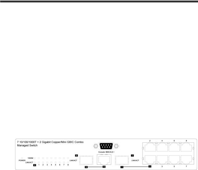
2.2 Front Panel
The front panel of the CWGE9MS managed Ethernet switch consists of 7x auto-sensing
10/100/1000Mbps Ethernet RJ45 ports (automatic MDI/MDIX), 2 SFP/Giga copper combo ports, and the LED indicators are also located on the front panel of the switch.
Front Panel of the 7 10/100/1000TX + 2 10/100/1000T and 1000 SFP Combo Managed Switch
RJ45 Ports (Auto MDI/MDIX)
There are 7 10/100/1000 auto-sensing RJ45 ports for 10Base-T, 100Base-TX, or 1000Base-T connections. In general, MDI means connecting to another Hub or Switch while MDIX means connecting to a workstation or PC. Therefore, Auto MDI/MDIX means that you can connect to another Switch or workstation without changing non-crossover or crossover cabling.
11
2 SFP/Giga copper combo port
Traditional RJ45 ports can be used for unlinking wide-band paths in short distance (<100m), or the appropriate replaceable mini-GBIC ports can be used for the application of wideband unlinking and long distance transmissions to fit the flexible field request.
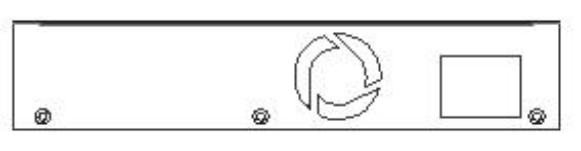
2.3 Rear Panel
The 3-pronged power plug are located at the rear panel of the CWGE9MS managed Ethernet switch as shown in figure. The switch will work with AC in the range 100-240V
AC, 50-60Hz.
Rear panel of the CWGE9MS managed Ethernet switch
12
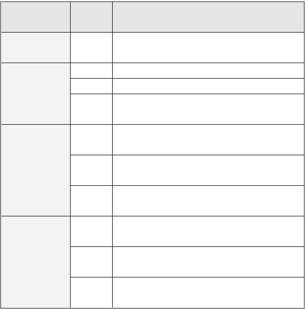
2.4 LED Indicators
The following table provides descriptions of the LED statuses and meaning. They provide a real-time indication of systematic operation status.
LED |
Status |
Description |
|
Power |
Green |
Power On |
|
|
Yellow |
The port is operating at the speed of 1000Mbps. |
|
1000M |
Amber |
The port is operating at the speed of 100Mbps. |
|
|
The port is operating at the speed of 10Mbps or |
||
|
Off |
||
|
no device attached |
||
|
|
||
|
Green |
The port is successfully connecting with the |
|
|
device. |
||
|
|
||
LNK / ACT |
Blinks |
The port is receiving or transmitting data. |
|
|
Off |
No device attached. |
|
|
Green |
The port is successfully connecting with the |
|
|
device. |
||
|
|
||
LNK / ACT |
Blinks |
The port is receiving or transmitting data. |
|
(SFP) |
|||
|
|
||
|
Off |
No device attached. |
13

Chapter 3 Hardware Installation
3.1 Desktop Installation
Set the switch on a sufficiently large flat space with a power outlet nearby. The surface where you put your Switch should be clean, smooth, level, and sturdy. Make sure there is enough clearance around the Switch to allow attachment of cables, power cord and air circulation.
3.2Attaching Rubber Feet
1.Make sure mounting surface on the bottom of the switch is grease and dust free.
2.Remove adhesive backing from your rubber feet.
3.Apply the rubber feet to each corner on the bottom of the switch. These footpads can prevent the switch from shock/vibration.
3.3Power On
Connect the power cord to the power socket on the rear panel of the Switch. The other side of power cord connects to the power outlet. The internal power works with AC in the voltage range 90-240VAC, frequency 50~60Hz. Check the power indicator on the front panel to see if power is properly supplied.
14
Chapter 4 Network Application
This section provides you a few samples of network topology in which the switch is used.
In general, the CWGE9MS managed Ethernet switch is designed to be used as a desktop or segment switch.
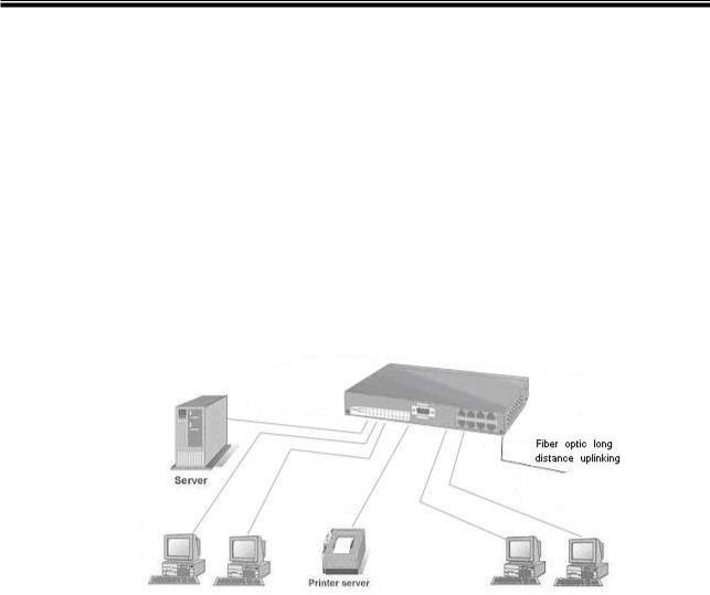
4.1 Desktop Application
The CWGE9MS managed Ethernet switch is designed to be a desktop size switch that is an ideal solution for small workgroup. The switch can be used as a standalone switch to which personal computers, server, printer server are directly connected to form small workgroup.
4.2 Segment Application
For enterprise networks where large data broadcast are constantly processed, this switch is suitable for department user to connect to the corporate backbone.
15
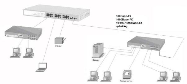
You can use the CWGE9MS managed Ethernet switch to connect PCs, workstations, and servers to each other by connecting these devices directly to the switch. All the devices in this network can communicate with each other. Connecting servers to the backbone switch allow other users to access the server’s data.
The switch automatically learns node address, which are subsequently used to filter and forward all traffic based on the destination address. You can use any of the RJ45 port of the CWGE9MS managed Ethernet switch to connect with another Switch or Hub to interconnect each of your small-switched workgroups to form a larger switched network.
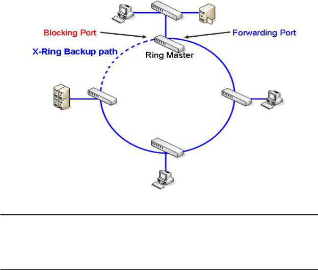
4.3 X-Ring Application
This industrial switch supports the X-Ring protocol that can help the network system to recovery from network connection failure within 300ms, making the network system more reliable. The X-Ring algorithm is similar to spanning tree protocol (STP) algorithm but the recovery time is faster than STP. The following figure is a sample X-Ring configuration.
16
[NOTE]
When the X-Ring function is enabled, the user must disable the RSTP. The X-Ring function and RSTP function cannot operate simultaneously.
With X-Ring topology, every switch enables the X-Ring function and assigns two member ports in the ring. Only one switch in the X-Ring group would be the backup switch with one of the two member ports’ being a backup port then switches are called working switches’ working ports. When the network connection fails, the backup port will automatically become a working port to the failure. In the X-Ring group, switches are setting in “slave mode” by default, but one must be the “master mode”. If there are 2 or more switches in the master mode, then software will automatically select the switch with lowest MAC address number as the ring master. The ringmaster has the rights to negotiate and command to other switches in the X-Ring group.
If a link fails the ringmaster is alerted and invokes its secondary port to rebuild the
17
network detection of the failed link’s activation of the master’s backup link and address table. If the failed link is restored, the ring slaves will alert the ringmaster to restore normal operation by disabling the backup link on the network in less than 300ms.
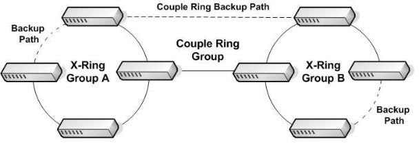
4.4 Coupling Ring Application
Within the network there may be more than one X-Ring group. By using the coupling ring function, it can connect each X-Ring for redundant backup. It can ensure the transmission between two ring groups will not fail. The following figure is a sample of a coupling ring application. The couple ring consists of four switches—switch 1 through switch 4 that are connected to each other via the paths in red. Please note that the Coupling Ring Backup Path between switch 1 and switch 3 is blocked; it will work only when the path between switch 2 and switch 4 is broken or disconnected.
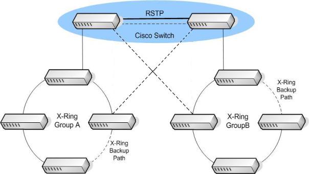
4.5 Dual Homing Application
It provides the connection loss from between X-Ring group and an upper level/core switch. Assign two ports to be the Dual Homing port that is backup port in the X-Ring group. The Dual Homing function only works when the X-Ring function is active. Each X-Ring group only has one Dual Homing port.
18
19
Chapter 5 Console Management
5.1 Connecting to the Console Port
Use the supplied RS-232 cable to connect a terminal or PC to the console port. The terminal or PC to be connected must support the terminal emulation program.
Connecting the switch to a terminal via RS-232 cable
5.2 Login in the Console Interface
When the connection between Switch and PC is ready, turn on the PC and run a terminal emulation program or Hyper Terminal and configure its communication parameters to match the following default characteristics of the console port:
Baud Rate: 9600 bps
Data Bits: 8
Parity: none
Stop Bit: 1
Flow control: None
20

The settings of communication parameters
After finished the parameter settings, select “OK“. When the blank screen shows up, press Enter key to bring out the login prompt. Key in the “admin“ (default value) for the both User name and Password (use Enter key to switch), then press Enter key and the
Main Menu of console management appears. Please see below figure for login screen.
Console login interface
21

5.3 CLI Management
The system supports two types of console management – CLI command. After you login to the system, you will see a command prompt. To enter CLI management interface, enter “enable” command. The following table lists the CLI commands and description.
Commands Level
Modes |
Access Method |
Prompt |
Exit Method |
About This Mode1 |
User EXEC |
Begin a session |
switch> |
Enter logout |
The user commands |
|
with your |
|
or quit. |
available at the user level |
|
switch. |
|
|
are a subset of those |
|
|
|
|
available at the privileged |
|
|
|
|
level. |
|
|
|
|
Use this mode to |
|
|
|
|
• Perform basic tests. |
|
|
|
|
• Display system |
|
|
|
|
information. |
Privileged |
Enter the |
switch# |
Enter |
The privileged command is |
EXEC |
enable |
|
disable to |
advance mode |
|
command while |
|
exit. |
Privileged this mode to |
|
in user EXEC |
|
|
• Display advance function |
|
mode. |
|
|
status |
|
|
|
|
• Save configures |
Global |
Enter the |
switch |
To exit to |
Use this mode to configure |
Configuration |
configure |
(config)# |
privileged |
parameters that apply to |
|
command while |
|
EXEC |
your switch as a whole. |
|
in privileged |
|
mode, enter |
|
|
EXEC mode. |
|
exit or end |
|
22

VLAN |
Enter the vlan |
switch |
To exit to |
Use this mode to configure |
database |
database |
(vlan)# |
user EXEC |
VLAN-specific parameters. |
|
command while |
|
mode, enter |
|
|
in privileged |
|
exit. |
|
|
EXEC mode. |
|
|
|
Interface |
Enter the |
switch |
To exit to |
Use this mode to configure |
configuration |
interface |
(config-if)# |
global |
parameters for the switch |
|
command (with |
|
configuration |
and Ethernet ports. |
|
a specific |
|
mode, enter |
|
|
interface) while |
|
exit. To exit |
|
|
in global |
|
to privileged |
|
|
configuration |
|
EXEC mode, |
|
|
mode |
|
enter end. |
|
23

Chapter 6 Web-Based Management
This section introduces the configuration and functions of the Web-based management.
6.1 About Web-based Management
Inside the CPU board of the switch exists an embedded HTML web site residing in flash memory. It offers advanced management features and allow users to manage the switch from anywhere on the network through a standard browser such as Microsoft Internet Explorer.
The Web-Based Management supports Internet Explorer 5.0. It is based on Java Applets with an aim to reduce network bandwidth consumption, enhance access speed and present an easy viewing screen.
[NOTE]: By default, IE5.0 or later version does not allow Java Applets to open sockets.
The user has to explicitly modify the browser setting to enable Java Applets to use network ports.
6.2 Preparing for Web Management
Before using web management, you can use console to login to the switch and check the default IP Address of the switch. Please refer to the Console Management Chapter for console login information. If you need to change the IP address the first time, you can use the console management mode to modify it. The default value is as below:
IP Address: 192.168.10.1 Subnet Mask: 255.255.255.0
Default Gateway: 192.168.10.254
24
User Name: admin Password: admin
6.3System Login
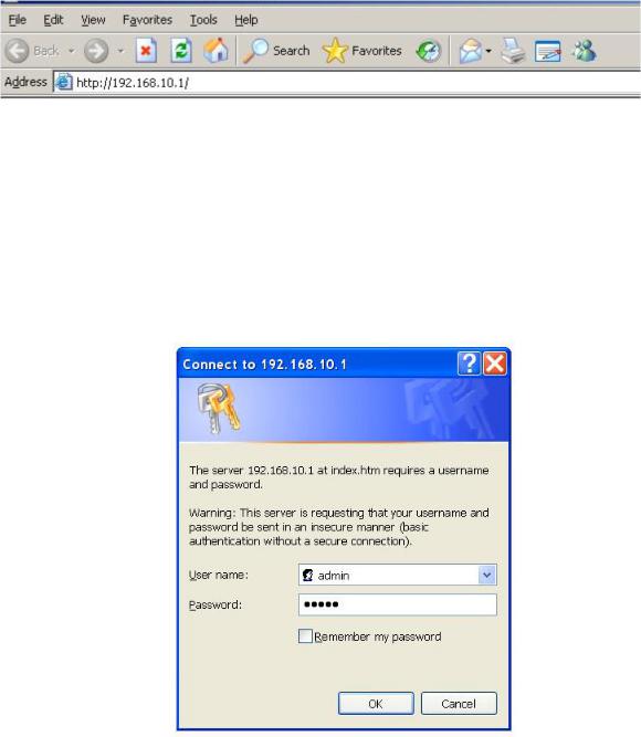
1.Launch the Internet Explorer on the PC
2.Key in “http:// “+” the IP address of the switch”, and then Press “Enter”.
Uniform Resource Locator
3.The login screen appears right after.
4.Key in the user name and password. The default user name and password are the same as ‘admin’
5.Press Enter or select OK button, and then the home screen of the Web-based management shows up.
Login screen
25
6.4 System Information
Assign the system name and location and view the system information.
!System Name: Assign the system name of the switch (The maximum length is 64 bytes)
!System Description: Describes the switch.
!System Location: Assign the switch physical location (The maximum length is 64 bytes).
!System Contact: Enter the name of contact person or organization.
!Firmware Version: Displays the switch’s firmware version
!Kernel Version: Displays the kernel software version
!MAC Address: Displays the unique hardware address assigned by manufacturer (default)
!And than, select  button.
6.5IP Configuration
User can configure the IP Settings and DHCP client function here.
!DHCP Client: Enable or disable the DHCP client function. When DHCP client function is enabled, the industrial switch will be assigned an IP address from the network DHCP server. The default IP address will be replaced by the assigned IP address on DHCP server. After the user selects the Apply button, a popup dialog box shows up. It is to inform the user that when the DHCP client is enabled, the current IP address will be lost and user should find the new IP address on the DHCP server.
!IP Address: Assign the IP address that the network is using. If DHCP client function is enabled, and then the user does not need to assign the IP address. The network DHCP server will assign the IP address displaying in this column for the industrial switch. The default IP is 192.168.10.1.
26
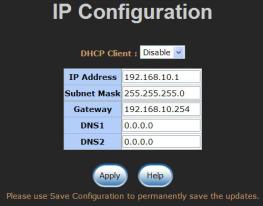
!Subnet Mask: Assign the subnet mask to the IP address. If DHCP client function is enabled, and then the user does not need to assign the subnet mask.
!Gateway: Assign the network gateway for the industrial switch. The default gateway is 192.168.10.254.
!DNS1: Assign the primary DNS IP address.
!DNS2: Assign the secondary DNS IP address.
!And then, select 
IP configuration interface
6.6 DHCP Server
DHCP is the abbreviation of Dynamic Host Configuration Protocol that is a protocol for assigning dynamic IP addresses to devices on a network. With dynamic addressing, a device can have a different IP address every time it connects to the network. In some systems, the device's IP address can even change while it is still connected. DHCP also supports a mix of static and dynamic IP addresses. Dynamic addressing simplifies network administration because the software keeps track of IP addresses rather than requiring an administrator to manage the task. This means that a new computer can be added to a network without the hassle of manually assigning it a unique IP Address.
The system provides the DHCP server function. Enable the DHCP server function; the switch system will be a DHCP server.
27

6.6.1 System configuration
!DHCP Server: Enable or Disable the DHCP Server function. Enable—the switch will be the DHCP server on your local network.
!Low IP Address: Type in an IP address. Low IP address is the beginning of the dynamic IP range. For example, dynamic IP is in the range between 192.168.1.100
~ 192.168.1.200. In contrast, 192.168.1.100 is the Low IP address.
!High IP Address: Type in an IP address. High IP address is the end of the dynamic IP range. For example, dynamic IP is in the range between 192.168.1.100 ~ 192.168.1.200. In contrast, 192.168.1.200 is the High IP address.
!Subnet Mask: Type in the subnet mask of the IP configuration.
!Gateway: Type in the IP address of the gateway in your network.
!DNS: Type in the Domain Name Server IP Address in your network.
!Lease Time (sec): It is the time period that system will reset the dynamic IP assignment to ensure the dynamic IP will not been occupied for a long time or the server doesn’t know that the dynamic IP is idle.
!And then, select 
DHCP Server Configuration interface
28

6.6.2 Client Entries
When the DHCP server function is active, the system will collect the DHCP client information and displays it at this tab.
DHCP Client Entries interface
6.6.3 Port and IP Bindings
Assign the dynamic IP address to the port. When the device is connecting to the port and asks for IP assigning, the system will assign the IP address that has been assigned before to the connected device.
Port and IP Bindings interface
29
 Loading...