


INSTALLATION AND OPERATION MANUAL
FDW1000(M,S)
OPTICAL WIEGAND, MAGSTRIPE & F/2F DATA EXTENDER
This manual serves the following ComNet Model Numbers:
FDW1000M/C
FDW1000S/C
FDW1000M/R
FDW1000S/R
EXP100C
EXP100R
The ComNet™ FDW1000 data extenders provide optical connectivity between one card reader and its associated door or gate locking hardware, to any Wiegand, MagStripe, or F/2F-based control panel. The connection is completely supervised and secure, and a pair of these units will support a single locking gate or door and its associated reader using two multimode or singlemode optical fibers. The ComNet™ EXP100 Expansion Module enables additional Wiegand-based devices to be added to the network.
An auxiliary I/O (input/output) interface is available for determining door, gate, and control panel status and signaling, and a relay interface provides the door strike or gate activation functions. See Figures 10 and 11 beginning on Page 5 for a guide to the I/Os and Relay Controls.
The FDW1000 series are supplied as a remote unit for door or gate locations, and a central unit for control panel installation, managed by use of a Dip Switch on each unit. See Figures 3 through 5 on Page 3 for Central and Remote Dip Switch Settings.
These extenders are designed for long-term, reliable operation in harsh industrial environments, and a fault-specific LED indicator is provided for rapidly ascertaining the operating status of the extender and the link. See Figure 17 on Page 12 for an explanation of LED indicators.
Packaged in a rugged aluminum housing, these units are designed for shelf or surface mounting. See Figure A on Page 12 for mounting instructions.
See Figures 1 – 17 for complete installation details.
INS_FDW1000_EXP100_REV– 04/25/12 PAGE 1
INSTALLATION AND OPERATION MANUAL |
FDW1000(M,S) |
|
|
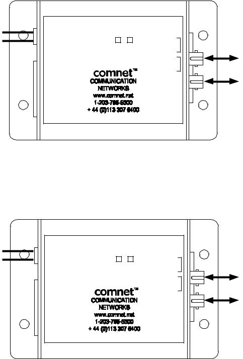
FIGURE 1 – FDW1000/C CENTRAL DATA EXTENDER
BLACK W/ WHITE STRIPE |
1 8 – 16VDC |
|
|
|
|
BLACK |
2 GND |
FDW1000 S M /C |
RLY 4 N.O. 1 |
|
|
|
|
||||
Power Supply: |
|
|
CENTRAL |
RLY 4 COM 2 |
MULTIMODE OR |
STATUS LED |
|
RLY 4 N.C. 3 |
|||
Input: |
|
DATA |
|||
|
RLY 3 N.O. 4 |
SINGLE MODE RX |
|||
8–16 VDC @ 300mA Max |
|
|
EXTENDER |
||
1 EXP(+) |
|
RLY 3 COM 5 |
OPTICAL FIBER |
||
Output: |
|
|
|||
2 EXP(–) |
|
|
RLY 3 N.C. 6 |
MULTIMODE OR |
|
+5 VDC @ 100mA |
3 +5V OUT |
|
|
GND 7 |
|
|
|
SINGLE MODE TX |
|||
|
4 PROG RES 2 |
|
AUX OUT 8 |
||
|
|
OPTICAL FIBER |
|||
|
5 PROG RES 1 |
|
RLY 2 IN 9 |
||
|
6 LED IN |
|
|
RLY 1 IN 10 |
|
7 D1/DOUT
8 D0/COUT
Optical Port TX must be connected to Optical Port RX on another FDW1000 unit. Similarly, Optical Port RX must be connected to Optical Port TX on another FDW1000 unit.
See Figure 8 on Page 4.
FIGURE 2 – FDW1000/R REMOTE DATA EXTENDER
BLACK W/ WHITE STRIPE |
1 8 – 16VDC |
|
|
|
|
BLACK |
2 GND |
FDW1000 S M |
/R |
RLY 2 N.O. 1 |
|
|
|
||||
|
STATUS LED |
REMOTE |
|
RLY 2 COM 2 |
MULTIMODE OR |
Power Supply: |
DATA |
|
RLY 2 N.C. 3 |
||
|
|
RLY 1 N.O. 4 |
SINGLE MODE RX |
||
Input: |
1 EXP(+) |
EXTENDER |
|
||
|
RLY 1 COM 5 |
OPTICAL FIBER |
|||
8–16 VDC @ 300mA Max |
|
|
|||
2 EXP(–) |
|
|
RLY 1 N.C. 6 |
MULTIMODE OR |
|
Output: |
3 +5V OUT |
|
|
GND 7 |
|
|
|
SINGLE MODE TX |
|||
+5 VDC @ 100mA |
4 RLY 4 IN |
|
|
AUX IN 8 |
|
|
|
OPTICAL FIBER |
|||
|
5 RLY 3 IN |
|
|
9 |
|
|
|
|
|
||
|
6 LED OUT |
|
|
10 |
|
7 D1/DIN
8 D0/CIN
Optical Port TX must be connected to Optical Port RX on another FDW1000 unit. Similarly, Optical Port RX must be connected to Optical Port TX on another FDW1000 unit.
See Figure 8 on Page 4.
TECH SUPPORT: 1.888.678.9427
INS_FDW1000_EXP100_REV– 04/25/12 PAGE 2
INSTALLATION AND OPERATION MANUAL |
FDW1000(M,S) |
|
|
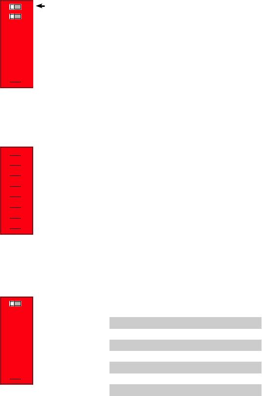
FIGURE 3 – CENTRAL UNIT SWITCH SETTINGS
Dip Switch is located beneath the casing of each unit.

 8 7 6 5 4 3 2 1
Expansion Module Setup
See Expandion Module information beginning on Page 8.
Pullup Resistors Enabled using Switch #4 ON = DISABLED
OFF = ENABLED
 ON
ON
FIGURE 4 – REMOTE UNIT SWITCH SETTINGS
Dip Switch is located beneath the casing of each unit.
 1
1 2
2 3
3
 4
4 5
5 6
6 7
7 8
8
 ON
ON
Expansion Module Setup
See Expandion Module information beginning on Page 8.
Pullup Resistors Enabled using Switch #4 ON = ENABLED
OFF = DISABLED
FIGURE 5 – DATA I/O SWITCH SETTINGS
Dip Switch is located beneath the casing of each unit. Data selection is made using switches 6, 7 and 8.
8 7 6 5 4 3 2 1
 ON
ON
}
|
|
Switch |
|
|
|
|
|
|
6 |
7 |
8 |
|
|
|
|
Wiegand |
OFF |
OFF |
OFF |
|
|
|
|
Wiegand / No Filter |
OFF |
OFF |
ON |
|
|
|
|
Strobed Rising Edge (MR-5) |
OFF |
ON |
OFF |
|
|
|
|
Strobed Rising Edge (Dorad0 644) |
OFF |
ON |
ON |
|
|
|
|
Strobed Rising (Mag-Tek) |
ON |
OFF |
OFF |
|
|
|
|
Strobed Falling Edge |
ON |
OFF |
ON |
|
|
|
|
Reserved |
ON |
ON |
OFF |
|
|
|
|
F2F |
ON |
ON |
ON |
|
|
|
|
TECH SUPPORT: 1.888.678.9427
INS_FDW1000_EXP100_REV– 04/25/12 PAGE 3

INSTALLATION AND OPERATION MANUAL |
FDW1000(M,S) |
|
|
FIGURE 6 – FDW1000/C TYPICAL CONNECTION
DC
Power |
1 8 – 16VDC |
|
RLY 4 N.O. 1 |
|
2 GND |
|
|
||
Supply |
|
|
RLY 4 COM 2 |
|
STATUS LED |
|
RLY 4 N.C. 3 |
RX |
|
|
|
|
RLY 3 N.O. 4 |
|
|
1 EXP(+) |
|
RLY 3 COM 5 |
|
|
|
|
||
|
|
RLY 3 N.C. 6 |
|
|
|
2 EXP(–) |
|
|
|
|
|
GND 7 |
|
|
|
3 +5V OUT |
|
TX |
|
|
|
AUX OUT 8 |
||
|
4 PROG RES |
2 |
||
Access |
RLY 2 IN 9 |
|
||
6 LED IN |
|
|
||
|
RLY 1 IN 10 |
|
||
Control |
5 PROG RES 1 |
|
|
|
8 D0/COUT |
|
|
|
|
|
7 D1/DOUT |
|
|
|
Panel
FIGURE 7 – FDW1000/R TYPICAL CONNECTION
DC
Power |
1 8 – 16VDC |
|
|
2 GND |
RLY 2 N.O. 1 |
|
|
Supply |
|
RLY 2 COM 2 |
|
STATUS LED |
RLY 2 N.C. 3 |
RX |
|
|
RLY 1 N.O. 4 |
||
|
|
||
|
1 EXP(+) |
RLY 1 COM 5 |
|
|
2 EXP(–) |
RLY 1 N.C. 6 |
|
|
3 +5V OUT |
GND 7 |
TX |
|
AUX IN 8 |
||
|
4 RLY 4 IN |
||
|
|
||
|
9 |
|
|
Card |
5 RLY 3 IN |
|
|
10 |
|
||
6 LED OUT |
|
||
|
|
|
|
Reader |
7 D1/DIN |
|
|
8 D0/CIN |
|
|
R1 Input Controls Strike on Remote
Door Strike
Output
FIGURE 8 – OPTIC CONNECTIONS
TX |
RX |
TX |
RX |
TECH SUPPORT: 1.888.678.9427
Bench Test and Set Up:
1.Connect the Remote and Central unit Fiber Optic ports together using a crossover connection as shown in the diagram.
2.Connect a suitable power supply to both units.
3.Apply power. After a short delay, both units’ Status LEDs should flash with a green pulse to indicate successful communication.
4.Touch a jumper wire from the GND connection to the RLY 3 input on the FDW1000/C. The relay should activate with an audible click. A VOM or continuity tester should show RLY 1 N.O. Contacts on the FDW1000/R closing when the RLY 1 input is connected to GND on the FDW1000/C.
5.FDW1000 ships preset for Wiegand data format. Refer to Figure 5 on Page 3 to set the Dip Switch to a different reader and panel format.
6.Connect a reader to the FDW1000/R and a panel to the FDW1000/C. Verify that card reads are being accepted by the access control system. Perform any troubleshooting before installing the units in the field.
7.If the EXP100 Expansion modules are used with this system, refer to EXP100 integration information beginning on Page 8.
8.When proper settings are verified, units are ready for final installation and operation.
INS_FDW1000_EXP100_REV– 04/25/12 PAGE 4
 Loading...