


This guide serves the following ComNet Model Numbers:
CNGE24FX12TX12MS
CNGE24FX12TX12MSPOE
INSTALLATION AND OPERATION MANUAL
CNGE24FX12TX12MS[POE]
Industrial Grade Managed Ethernet Switch w/
12 × 100/1000Base-FX + 12 × 10/100/1000Base-TX Ports w/ Optional 30W PoE
The ComNet CNGE24FX12TX12MS[POE] has twelve 100/1000Base-FX SFP* ports and twelve 10/100/1000Base-TX ports. All SFP ports utilize ComNet SFP modules for fiber and connector type and distance. The IEEE802.3-compliant unit offers multiple Ethernet redundancy protocols (MSTP/RSTP/STP/ERPS (G.8032)) which protect your applications from network interruptions or temporary malfunctions by redirecting transmission within the network. The switch provides advanced IP-based management that can limit the maximum bandwidth for each connected IP device, allowing the user to adjust usage. Application-based QoS can set a higher priority for data streaming. The Device-Binding function can prevent unauthorized network access, increasing security.
The CNGE24FX12TX12MSPOE models provide twelve electrical ports supporting up to thirty watts of power. All PoE ports are IEEE 802.3at compliant.
Each model is provided with redundant power inputs which can be either one mains voltage and one or two low voltage DC inputs or two low voltage DC inputs.
Rev. 2.22.18
INSTRUCTION MANUAL |
CNGE24FX12TX12MS[POE] |
Contents
Regulatory Compliance Statement |
6 |
Warranty |
6 |
Disclaimer |
6 |
Safety Information |
7 |
Hardware Installation |
8 |
Rack mount kit assembly |
8 |
Hardware Overview |
9 |
Power Supply |
10 |
Front Panel LEDs |
10 |
WEB Management |
11 |
Login |
11 |
Configuration |
15 |
Green Ethernet |
23 |
Thermal Protection |
25 |
DHCP |
28 |
DHCP Pool Configuration |
31 |
Security |
36 |
Network |
54 |
Screen |
57 |
Aggregation |
84 |
Loop Protection |
86 |
Spanning Tree |
87 |
IPMC Profile |
94 |
MVR |
97 |
IPMC |
99 |
LLDP |
107 |
PoE |
109 |
EPS |
111 |
Ethernet Protection Switch Configuration |
112 |
Ethernet Ring Protection Switch Configuration |
129 |
MAC Table |
132 |
TECH SUPPORT: 1.888.678.9427
INS_CNGE24FX12TX12MS[POE] Rev. 2.22.18 PAGE 2
INSTRUCTION MANUAL |
CNGE24FX12TX12MS[POE] |
VLAN Translation |
133 |
VLANs |
135 |
Private VLANs |
138 |
VCL |
140 |
Protocol-based VLAN |
141 |
Voice VLAN |
145 |
Mirroring & Remote Mirroring Configuration |
166 |
UPnP |
169 |
GVRP |
170 |
Monitor Menu |
172 |
System |
172 |
CUP Load |
173 |
System IP Status |
174 |
System Log |
175 |
Port State |
177 |
Green Ethernet |
178 |
Thermal Protection |
179 |
Ports |
179 |
QoS Statistics |
180 |
DHCP |
184 |
Security |
190 |
AAA |
198 |
Aggregation Status |
204 |
LACP |
205 |
Loop Protection |
207 |
MVR |
212 |
IPMC |
215 |
LLDP |
221 |
PoE |
226 |
MAC Table |
227 |
VLANs |
228 |
Diagnostics Menu |
231 |
Ping |
231 |
Ping6 |
232 |
PHYtest |
233 |
TECH SUPPORT: 1.888.678.9427
INS_CNGE24FX12TX12MS[POE] Rev. 2.22.18 PAGE 3
INSTRUCTION MANUAL |
CNGE24FX12TX12MS[POE] |
Maintenance Menu |
234 |
Restart Device |
234 |
Factory Defaults |
234 |
Software |
235 |
Configuration |
237 |
Using Switch CLI |
240 |
About CLI Management |
240 |
CLI Management by RS-232 Serial Console |
240 |
CLI Management by Telnet |
243 |
Commander Groups |
244 |
Quick Start |
245 |
Log In and Reset Configuration to Factory Default |
245 |
Set Device Hostname and Admin User Password |
246 |
Set VLAN 1 IP Address |
246 |
Display and Save Configuration to Flash |
248 |
ICLI Basics |
250 |
Command Structure and Syntax |
251 |
Syntax |
252 |
Ethernet Interface Naming |
254 |
Using the Keyboard |
256 |
Basic Line Editing |
256 |
Command History |
257 |
Context-Sensitive Help |
259 |
Using Context-Sensitive Help |
259 |
Long Lines and Pagination |
261 |
Other Special Keys |
262 |
Filtering Output |
262 |
Understanding Modes and Sub-Modes |
263 |
Using ‘do’ While in a Sub-Mode |
266 |
Changing Between ICLI Modes |
267 |
Understanding Privilege Levels |
268 |
Configuring Privilege Level Passwords |
269 |
Understanding Terminal Parameters |
270 |
Changing Terminal Parameters |
271 |
TECH SUPPORT: 1.888.678.9427
INS_CNGE24FX12TX12MS[POE] Rev. 2.22.18 PAGE 4
INSTRUCTION MANUAL |
CNGE24FX12TX12MS[POE] |
Using Banners |
273 |
Configuring Banners |
273 |
Configuring the System |
275 |
Configuration Example |
275 |
Resetting or Removing Condiguration with “no” |
277 |
Using “no” Forms |
277 |
Managing Users |
278 |
Adding, Modifying, and Deletion Users |
278 |
Using Show Commands |
279 |
Listing All Show Commands |
280 |
Show running-config |
283 |
Default vs. Non-default vs. All Defaults |
283 |
Show running-config [all-defaults] |
285 |
Show running-config feature feature_name [all-defaults] |
285 |
Show running-config interface list [all-defaults] |
286 |
Working with Configuration Files |
287 |
Reverting to Default Configuration |
288 |
Working with Configuration Files |
289 |
Using Reload Commands |
291 |
Working with Software Images |
292 |
Appendix A |
293 |
Ethernet Ring Protection Switching Example Configuration 293 |
|
Configuring ERPS from the Web GUI |
294 |
Ethernet Ring Protection Switching Configuration |
301 |
Configuring ERPS from the ICLI |
306 |
TECH SUPPORT: 1.888.678.9427
INS_CNGE24FX12TX12MS[POE] Rev. 2.22.18 PAGE 5
INSTRUCTION MANUAL |
CNGE24FX12TX12MS[POE] |
|
|
Regulatory Compliance Statement
Product(s) associated with this publication complies/comply with all applicable regulations. Please refer to the Technical Specifications section for more details.
Warranty
ComNet warrants that all ComNet products are free from defects in material and workmanship for a specified warranty period from the invoice date for the life of the installation. ComNet will repair or replace products found by ComNet to be defective within this warranty period, with shipment expenses apportioned by ComNet and the distributor. This warranty does not cover product modifications or repairs done by persons other than ComNet-approved personnel, and this warranty does not apply to ComNet products that are misused, abused, improperly installed, or damaged by accidents.
Please refer to the Technical Specifications section for the actual warranty period(s) of the product(s) associated with this publication.
Disclaimer
Information in this publication is intended to be accurate. ComNet shall not be responsible for its use or infringements on third-parties as a result of its use. There may occasionally be unintentional errors on this publication. ComNet reserves the right to revise the contents of this publication without notice.
TECH SUPPORT: 1.888.678.9427
INS_CNGE24FX12TX12MS[POE] Rev. 2.22.18 PAGE 6
INSTRUCTION MANUAL |
CNGE24FX12TX12MS[POE] |
|
|
Safety Information
»»Only ComNet service personnel can service the equipment. Please contact ComNet Technical Support.
»»The equipment should be installed in locations with controlled access, or other means of security, and controlled by persons of authority. When operating at temperatures above 51º C, the equipment surfaces will be hot to the touch. Installation in restricted access location is required for this case.
»»For POE models requiring a power supply not labeled LPS, the unit should be installed in a restricted access location using a 60950-1, 2nd Edition + Am. 1 + Am. 2 Certified power supply rated for the ambient temperature in which it is installed. Total derated power rating should be greater than the sum of the attached loads plus 30 W for the switch.
»»Use CDRH compliant SFP modules when using fiber connectivity with this device.
»»When used in Australia or New Zealand, the product is certified for intra building applications only, and should not be directly connected to network cables with outside plant routing.
TECH SUPPORT: 1.888.678.9427
INS_CNGE24FX12TX12MS[POE] Rev. 2.22.18 PAGE 7
INSTRUCTION MANUAL |
CNGE24FX12TX12MS[POE] |
Hardware Installation
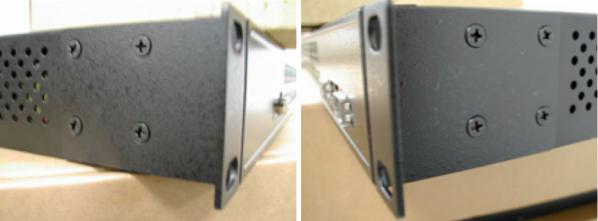
Rack mount kit assembly
You can find the rack mount kit and the screws in the packing box. Please assembly the rack mount kit on the switch with screws as shown below:
TECH SUPPORT: 1.888.678.9427
INS_CNGE24FX12TX12MS[POE] Rev. 2.22.18 PAGE 8

INSTRUCTION MANUAL |
CNGE24FX12TX12MS[POE] |
Hardware Overview
1 |
2 |
3 |
4 |
CNGE24FX12TX12MS[POE] Front Panel
Call-out Description
1Status LED
212 × 10/100/1000Base-TX RJ45 Ports
312 × 100/1000Base-FX SFP Ports
4USB Console Port
3 |
4 |
2 |
1 |
CNGE24FX12TX12MS[POE] Rear Panel
Call-out Description
11 × Mains Power Switch
21 × 90-240 VAC Mains Power Input
32 × 6-14 VDC or 48-57 VDC (model dependent) Redundant Power Input 2-Pin Terminal Block Connector
4Fault Relay 2-Pin Terminal Block Connector
TECH SUPPORT: 1.888.678.9427
INS_CNGE24FX12TX12MS[POE] Rev. 2.22.18 PAGE 9
INSTRUCTION MANUAL |
CNGE24FX12TX12MS[POE] |
Power Supply
For CNGE24FX12TX12MS Models, Power Supply must be 6 to 14 VDC @ 30 W max or 90-240 VAC mains.
For CNGE24FX12TX12MSPOE Model, Power Supply must be 48 to 57 VDC @ 390 W max or 90-240 VAC mains.
IMPORTANT SAFEGUARDS:
A)Elevated Operating Ambient - If installed in a closed or multi-unit rack assembly, the operating ambient temperature of the rack environment may be greater than room ambient. Therefore, consideration should be given to installing the equipment in an environment compatible with the maximum ambient temperature (Tma) specified by the manufacturer.
B)Reduced Air Flow - Installation of the equipment in a rack should be such that the amount of air flow required for safe operation of the equipment is not compromised.
Front Panel LEDs
LED |
Color |
Status |
Description |
Status |
Green |
On |
Switch is operational |
Gigabit Ethernet ports |
|
|
|
Link |
Amber |
On |
Port in Full Duplex mode |
Activity |
Green |
Blinking |
Data transmitted |
Gigabit SFP ports |
|
|
|
Link/Activity |
Green |
Blinking |
Data transmitted |
TECH SUPPORT: 1.888.678.9427
INS_CNGE24FX12TX12MS[POE] Rev. 2.22.18 PAGE 10
INSTRUCTION MANUAL |
CNGE24FX12TX12MS[POE] |
WEB Management
Login
Open a web browser and navigate to the switch using http:// and the IP address of the switch.
The default IP address is 192.168.10.1
This is the main login page. Default user name is “admin” with maximum length 32 Default password is “admin” with maximum length 32.
Warning – Any changes made to the settings will apply only to the current running configuration of the switch and will be lost in the event of a power cycle.
To save any changes made to persistent memory please go to "Maintenance ¦ Configuration ¦ Save startup-config" to write the changes to the switches startup configuration.
TECH SUPPORT: 1.888.678.9427
INS_CNGE24FX12TX12MS[POE] Rev. 2.22.18 PAGE 11

INSTRUCTION MANUAL |
CNGE24FX12TX12MS[POE] |
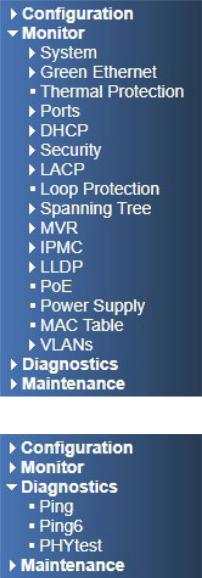
Menu Trees
The following tree views show the available menus within the switch web GUI. It offers the user quick access to all the configuration settings within the switch.
Configuration Menu
TECH SUPPORT: 1.888.678.9427
INS_CNGE24FX12TX12MS[POE] Rev. 2.22.18 PAGE 12
INSTRUCTION MANUAL |
CNGE24FX12TX12MS[POE] |
Monitor Menu
Diagnostics Menu
TECH SUPPORT: 1.888.678.9427
INS_CNGE24FX12TX12MS[POE] Rev. 2.22.18 PAGE 13

INSTRUCTION MANUAL |
CNGE24FX12TX12MS[POE] |
Maintenance Menu
TECH SUPPORT: 1.888.678.9427
INS_CNGE24FX12TX12MS[POE] Rev. 2.22.18 PAGE 14
INSTRUCTION MANUAL |
CNGE24FX12TX12MS[POE] |
Configuration
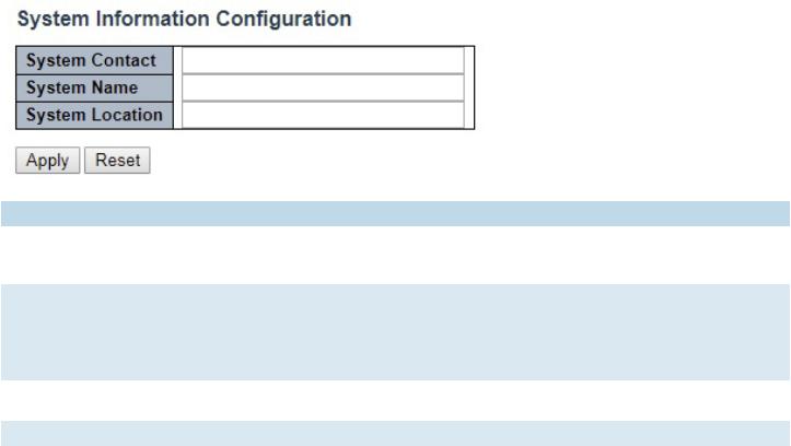
System Information
The switch system information is provided here.
Object |
Description |
System Contact |
The textual identification of the contact person for this managed node, together with |
|
information on how to contact this person. The allowed string length is 0 to 255, and the allowed |
|
content is the ASCII characters from 32 to 126. |
System Name |
An administratively assigned name for this managed node. By convention, this is the node’s fully- |
|
qualified domain name. A domain name is a text string drawn from the alphabet (A-Za-z), digits |
|
(0-9), minus sign (-). No space characters are permitted as part of a name. The first character |
|
must be an alpha character. And the first or last character must not be a minus sign. The allowed |
|
string length is 0 to 255. |
System Location |
The physical location of this node (e.g., telephone closet, 3rd floor). The allowed string length is |
|
0 to 255, and the allowed content is the ASCII characters from 32 to 126. |
Apply |
Click to apply changes without saving. * |
Reset |
Click to revert to previous values. |
Save to startup-config is under Maintenance Menu tree.
TECH SUPPORT: 1.888.678.9427
INS_CNGE24FX12TX12MS[POE] Rev. 2.22.18 PAGE 15

INSTRUCTION MANUAL |
CNGE24FX12TX12MS[POE] |
System IP
Configure IP basic settings, control IP interfaces and IP routes. The maximum number of interfaces supported is 8 and the maximum number of routes is 32.
Object |
Description |
IP Configuration |
|
Mode |
Configure whether the IP stack should act as a Host or a Router. In Host mode, IP traffic |
|
between interfaces will not be routed. In Router mode traffic is routed between all |
|
interfaces. |
DNS Server |
This setting controls the DNS name resolution done by the switch. The following modes are |
|
supported: |
|
• From any DHCP interfaces |
|
The first DNS server offered from a DHCP lease to a DHCP-enabled interface will be used. |
|
• No DNS server |
|
No DNS server will be used. |
|
• Configured |
|
Explicitly provide the IP address of the DNS Server in dotted decimal notation. |
|
• From this DHCP interface |
|
Specify from which DHCP-enabled interface a provided DNS server should be preferred. |
DNS Proxy |
When DNS proxy is enabled, system will relay DNS requests to the currently configured |
|
DNS server, and reply as a DNS resolver to the client devices on the network. |
IP Interfaces |
|
Delete |
Select this option to delete an existing IP interface. |
VLAN |
The VLAN associated with the IP interface. Only ports in this VLAN will be able to access the |
|
IP interface. This field is only available for input when creating a new interface. |
IPv4 DHCP Enabled |
Enable the DHCP client by checking this box. If this option is enabled, the system will |
|
configure the IPv4 address and mask of the interface using the DHCP protocol. The DHCP |
|
client will announce the configured System Name as hostname to provide DNS lookup. |
IPv4 DHCP Fallback |
The number of seconds for trying to obtain a DHCP lease. After this period expires, a |
Timeout |
configured IPv4 address will be used as IPv4 interface address. A value of zero disables the |
|
fallback mechanism, such that DHCP will keep retrying until a valid lease is obtained. Legal |
|
values are 0 to 4294967295 seconds. |
TECH SUPPORT: 1.888.678.9427
INS_CNGE24FX12TX12MS[POE] Rev. 2.22.18 PAGE 16
INSTRUCTION MANUAL |
CNGE24FX12TX12MS[POE] |
|
Object |
Description |
|
IPv4 DHCP Current |
For DHCP interfaces with an active lease, this column shows the current interface address, |
|
Lease |
as provided by the DHCP server. |
|
IPv4 Address |
The IPv4 address of the interface in dotted decimal notation. |
|
|
If DHCP is enabled, this field configures the fallback address. The field may be left blank if |
|
|
IPv4 operation on the interface is not desired - or no DHCP fallback address is desired. |
|
IPv4 Mask |
The IPv4 network mask, in number of bits (prefix length). Valid values are between 0 and |
|
|
30 bits for an IPv4 address.If DHCP is enabled, this field configures the fallback address |
|
|
network mask. The field may be left blank if IPv4 operation on the interface is not desired - |
|
|
or no DHCP fallback address is desired. |
|
DHCPv6 Enable |
Enable the DHCPv6 client by checking this box. If this option is enabled, the system will |
|
|
configure the IPv6 address of the interface using the DHCPv6 protocol. |
|
DHCPv6 Rapid Commit Enable the DHCPv6 Rapid-Commit option by checking this box. If this option is enabled, the DHCPv6 client terminates the waiting process as soon as a Reply message with a Rapid Commit option is received. This option is only manageable when DHCPv6 client is enabled.
DHCPv6 Current Lease For DHCPv6 interface with an active lease, this column shows the interface address provided by the DHCPv6 server.
IPv6 Address |
The IPv6 address of the interface. An IPv6 address is in 128-bit records represented as eight |
|
fields of up to four hexadecimal digits with a colon separating each field (:). For example, |
|
fe80::215:c5ff:fe03:4dc7. The symbol :: is a special syntax that can be used as a shorthand |
|
way of representing multiple 16-bit groups of contiguous zeros; but it can appear only once. |
|
It can also represent a legally valid IPv4 address. For example, ::192.1.2.34. |
|
The field may be left blank if IPv6 operation on the interface is not desired. |
IPv6 Mask |
The IPv6 network mask, in number of bits (prefix length). Valid values are between 1 and |
|
128 bits for an IPv6 address. |
|
The field may be left blank if IPv6 operation on the interface is not desired. |
Default Gateway |
|
Address |
The IP address of the gateway valid format is dotted decimal notation. |
IP Routes |
|
Delete |
Select this option to delete an existing IP route. |
Network |
The destination IP network or host address of this route. Valid format is notation or a valid |
|
IPv6 notation. A default route can use the value 0.0.0.0or IPv6 :: notation. |
Mask Length |
The destination IP network or host mask, in number of bits (prefix length). It defines how |
|
much of a network address that must match, in order to qualify for this route. Valid values |
|
are between 0 and 32 bits respectively 128 for IPv6 routes. Only a default route will have a |
|
mask length of 0 (as it will match anything). |
Gateway |
The IP address of the IP gateway. Valid format is notation or a valid IPv6 notation. Gateway |
|
and Network must be of the same type. |
Next Hop VLAN |
The VLAN ID (VID) of the specific IPv6 interface associated with the gateway. The given VID |
(Only for IPv6) |
ranges from 1 to 4094 and will be effective only when the corresponding IPv6 interface is |
|
valid. |
|
If the IPv6 gateway address is link-local, it must specify the next hop VLAN for the gateway. |
|
If the IPv6 gateway address is not link-local, system ignores the next hop VLAN for the |
|
gateway. |
Add Interface |
Click to add a new IP Interface. A maximum of 8 interfaces is supported. |
Add Route |
Click to add a new IP route. A maximum of 32 routes is supported. |
TECH SUPPORT: 1.888.678.9427
INS_CNGE24FX12TX12MS[POE] Rev. 2.22.18 PAGE 17

INSTRUCTION MANUAL |
CNGE24FX12TX12MS[POE] |
|
Object |
Description |
|
Apply |
Click to apply changes. |
|
Reset |
Click to revert to previous values. |
|
TECH SUPPORT: 1.888.678.9427
INS_CNGE24FX12TX12MS[POE] Rev. 2.22.18 PAGE 18

INSTRUCTION MANUAL |
CNGE24FX12TX12MS[POE] |
System NTP
Configure NTP on this page.
Object |
Description |
Mode |
Indicates the NTP mode operation. Possible modes are: Enabled: Enable NTP client mode operation. |
|
Disabled: Disable NTP client mode operation. |
Server # Provide the IPv4 or IPv6 address of a NTP server. IPv6 address is in 128-bit records represented |
|
|
as eight fields of up to four hexadecimal digits with a colon separating each field (:). For example, |
|
‘fe80::215:c5ff:fe03:4dc7’. The symbol ‘::’ is a special syntax that can be used as a shorthand way |
|
of representing multiple 16-bit groups of contiguous zeros; but it can appear only once. It can also |
|
represent a legally valid IPv4 address. For example, ‘::192.1.2.34’. |
Apply |
Click to apply changes. |
Reset |
Click to revert to previous values. |
TECH SUPPORT: 1.888.678.9427
INS_CNGE24FX12TX12MS[POE] Rev. 2.22.18 PAGE 19

INSTRUCTION MANUAL |
CNGE24FX12TX12MS[POE] |
System Time
This page allows you to configure the Time Zone.
Object Description Time Zone Configuration
Time ZoneLists various Time Zones worldwide. Select appropriate Time Zone from the drop down
Acronym |
User can set the acronym of the time zone. This is a User configurable acronym to identify the time zone. ( |
|
Range : Up to 16 characters ) |
Daylight Saving Time Configuration |
|
Daylight |
This is used to set the clock forward or backward according to the configurations set below for a defined |
Saving |
Daylight Saving Time duration. Select ‘Disable’ to disable the Daylight Saving Time configuration. Select |
Time |
‘Recurring’ and configure the Daylight Saving Time duration to repeat the configuration every year. Select |
|
‘Non-Recurring’ and configure the Daylight Saving Time duration for single time configuration. ( Default : |
|
Disabled ) |
Recurring Configurations |
|
Start time settings |
|
Week |
Select the starting week number. |
Day |
Select the starting day. |
Month |
Select the starting month. |
Hours |
Select the starting hour. |
Minutes |
Select the starting minute |
End time settings |
|
Week |
Select the ending week number. |
TECH SUPPORT: 1.888.678.9427
INS_CNGE24FX12TX12MS[POE] Rev. 2.22.18 PAGE 20
INSTRUCTION MANUAL |
CNGE24FX12TX12MS[POE] |
|
Object |
Description |
|
Day |
Select the ending day. |
|
Month |
Select the ending month. |
|
Hours |
Select the ending hour. |
|
Minutes |
Select the ending minute |
|
Offset settings |
|
|
Offset |
Enter the number of minutes to add during Daylight Saving Time. ( Range: 1 to 1440 ) |
|
Non Recurring Configurations |
|
|
Start time settings |
|
|
Month |
Select the starting month. |
|
Date |
Select the starting date. |
|
Year |
Select the starting year. |
|
Hours |
Select the starting hour. |
|
Minutes |
Select the starting minute |
|
End time settings |
|
|
Month |
Select the ending month. |
|
Date |
Select the ending date. |
|
Year |
Select the ending year. |
|
Hours |
Select the ending hour. |
|
Minutes |
Select the ending minute |
|
Offset settings |
|
|
Offset |
Enter the number of minutes to add during Daylight Saving Time. ( Range: 1 to 1440 ) |
|
TECH SUPPORT: 1.888.678.9427
INS_CNGE24FX12TX12MS[POE] Rev. 2.22.18 PAGE 21

INSTRUCTION MANUAL |
CNGE24FX12TX12MS[POE] |
System Log
Configure System Log on this page.
Object |
Description |
Server Mode |
Indicates the server mode operation. When the mode operation is enabled, the syslog message |
|
will send out to syslog server. The syslog protocol is based on UDP communication and received |
|
on UDP port 514 and the syslog server will not send acknowledgments back sender since UDP is a |
|
connectionless protocol and it does not provide acknowledgments. The syslog packet will always |
|
send out even if the syslog server does not exist. Possible modes are: |
|
Enabled: Enable server mode operation. |
|
Disabled: Disable server mode operation. |
Server Address |
Indicates the IPv4 host address of syslog server. If the switch provide DNS feature, it also can be a |
|
host name. |
Syslog Level |
Indicates what kind of messages will sent to the syslog server. Possible modes are: |
|
Error: Send the specific messages which severity code is less or equal than Error(3). |
|
Warning: Send the specific messages which severity code is less or equal than Warning(4). |
|
Notice: Send the specific messages which severity code is less or equal than Notice(5). |
|
Informational: Send the specific messages which severity code is less or equal than |
|
Informational(6). |
Apply |
Click to apply changes. |
Revert |
Click to revert to previous values. |
TECH SUPPORT: 1.888.678.9427
INS_CNGE24FX12TX12MS[POE] Rev. 2.22.18 PAGE 22
INSTRUCTION MANUAL |
CNGE24FX12TX12MS[POE] |
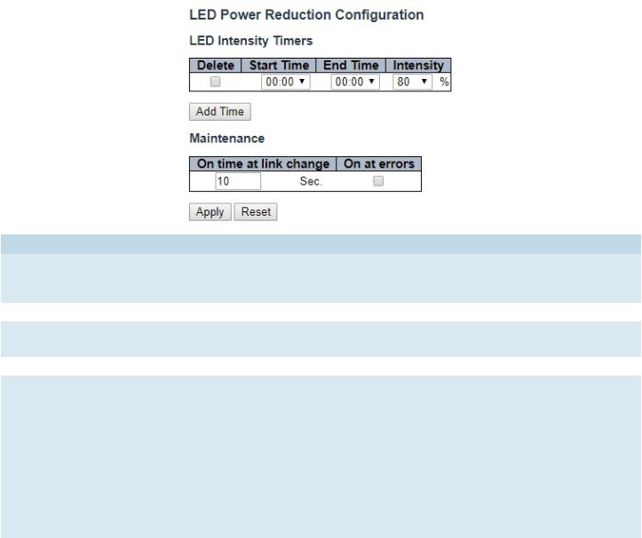
Green Ethernet
LED
Object |
Description |
LEDs Intensity |
The LEDs power consumption can be reduced by lowering the LEDs intensity. LEDs intensity could |
|
for example be lowered during night time, or they could be turn completely off. It is possible to |
|
configure 24 different hours of the day, at where the LEDs intensity should be set. |
Start Time |
The time at which the LEDs intensity shall be set to the corresponding intensity. |
End Time |
The time at which the LEDs intensity shall be set to a new intensity. If no intensity is specified for |
|
the next hour, the intensity is set to default intensity. |
Intensity |
The LEDs intensity (100% = Full power, 0% = LED off). |
Maintenance |
On time at link change |
|
When a network administrator does maintenance of the switch (e.g. adding or moving users) he |
|
might want to have full LED intensity during the maintenance period . Therefore it is possible to |
|
specify that the LEDs shall use full intensity a specific period of time. Maintenance Time is the |
|
number of seconds that the LEDs will have full intensity after either a port has changed link state, |
|
or the LED pushbutton has been pushed. Valid range is from 0 to 65535 seconds. |
|
On at errors |
|
In the case where maximum power saving is enabled by turning the LEDs completely off, it might |
|
be convenient to indicate to the network administrator that an error has been recorded in the |
|
system log. By checking the "On at errors" the LEDs will be turned on at 100% in the case that |
|
errors are logged in the system log. |
TECH SUPPORT: 1.888.678.9427
INS_CNGE24FX12TX12MS[POE] Rev. 2.22.18 PAGE 23
INSTRUCTION MANUAL |
CNGE24FX12TX12MS[POE] |
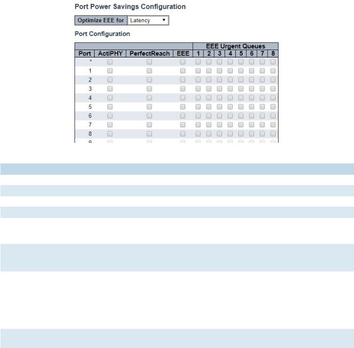
Port Power Savings
This page allows the user to configure the port power saving features.
Object Description
Port Power Savings Configuration
Optimize EEE for |
The switch can be set to optimize EEE for either best power saving or least traffic latency. |
Port Configuration |
|
Port |
The switch port number of the logical port. |
ActiPHY |
Link down power savings enabled. |
|
ActiPHY works by lowering the power for a port when there is no link. The port is power up for |
|
short moment in order to determine if cable is inserted. |
PerfectReach |
Cable length power savings enabled. |
|
PerfectReach works by determining the cable length and lowering the power for ports with |
|
short cables. |
EEE |
Controls whether EEE is enabled for this switch port. For maximizing power savings, the circuit |
|
isn’t started at once transmit data is ready for a port, but is instead queued until a burst of data |
|
is ready to be transmitted. This will give some traffic latency. |
|
If desired it is possible to minimize the latency for specific frames, by mapping the frames to a |
|
specific queue (done with QOS), and then mark the queue as an urgent queue. When an urgent |
|
queue gets data to be transmitted, the circuits will be powered up at once and the latency will |
|
be reduced to the wakeup time. |
EEE Urgent Queues Queues set will activate transmission of frames as soon as data is available.
Otherwise the queue will postpone transmission until a burst of frames can be transmitted.
TECH SUPPORT: 1.888.678.9427
INS_CNGE24FX12TX12MS[POE] Rev. 2.22.18 PAGE 24

INSTRUCTION MANUAL |
CNGE24FX12TX12MS[POE] |
Thermal Protection
This page allows the user to inspect and configure the current setting for controlling thermal protection. Thermal protection is used to protect the chip from getting overheated.
When the temperature exceeds the configured thermal protection temperature, ports will be turned off in order to decrease the power consumption. It is possible to arrange the ports with different groups. Each group can be given a temperature at which the corresponding ports shall be turned off.
Object |
Description |
Temperature |
The temperature at which the ports with the corresponding group will be turned off. |
|
Temperatures between 0 and 255 C are supported. |
Group |
The group the port belongs to. 4 groups are supported. |
TECH SUPPORT: 1.888.678.9427
INS_CNGE24FX12TX12MS[POE] Rev. 2.22.18 PAGE 25
INSTRUCTION MANUAL |
CNGE24FX12TX12MS[POE] |
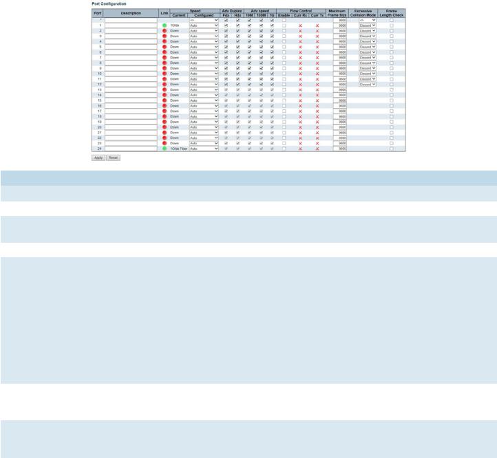
Ports
This page displays curent port configurations. Ports can also be configured here.
Object |
Description |
Port |
This is the logical port number for this row. |
Description |
The description of the port. It is an ASCII string no longer than 256 characters. |
Link |
The current link state is displayed graphically. Green indicates the link is up and red that it is |
|
down. |
Current Link Speed |
Provides the current link speed of the port. |
Configured Link |
Selects any available link speed for the given switch port. Only speeds supported by the |
Speed |
specific ports are shown. Possible speeds are: |
|
Disabled - Disables the switch port operation. |
|
Auto - Port auto negotiating speed with the link partner and selects the highest speed that is |
|
compatible with the link partner. |
|
10Mbps HDX - Forces the cu port in 10Mbps half duplex mode. |
|
10Mbps FDX - Forces the cu port in 10Mbps full duplex mode. |
|
100Mbps HDX - Forces the cu port in 100Mbps half duplex mode. |
|
100Mbps FDX - Forces the cu port in 100Mbps full duplex mode. |
|
1Gbps FDX - Forces the port in 1Gbps full duplex. |
|
2.5Gbps FDX - Forces the port in 2.5Gbps full duplex mode. |
Advertise Duplex |
When duplex is set as auto i.e auto negotiation, the port will only advertise the specified |
|
duplex as either Fdx or Hdx to the link partner. By default port will advertise all the supported |
|
duplexes if the Duplex is Auto. |
Advertise Speed |
When Speed is set as auto i.e auto negotiation, the port will only advertise the specified |
|
speeds (10M 100M 1G) to the link partner. By default port will advertise all the supported |
|
speeds if speed is set as Auto. |
Flow Control |
When Auto Speed is selected on a port, this section indicates the flow control capability that |
|
is advertised to the link partner. |
|
When a fixed-speed setting is selected, that is what is used. The Current Rx column indicates |
|
whether pause frames on the port are obeyed, and the Current Tx column indicates whether |
|
pause frames on the port are transmitted. The Rx and Tx settings are determined by the result |
|
of the last Auto-Negotiation. |
|
Check the configured column to use flow control. This setting is related to the setting for |
|
Configured Link Speed. |
TECH SUPPORT: 1.888.678.9427
INS_CNGE24FX12TX12MS[POE] Rev. 2.22.18 PAGE 26
INSTRUCTION MANUAL |
CNGE24FX12TX12MS[POE] |
|
Object |
Description |
|
Maximum Frame Size |
Enter the maximum frame size allowed for the switch port, including FCS. |
|
Excessive Collision |
Configure port transmit collision behavior. |
|
Mode |
Discard: Discard frame after 16 collisions (default). |
|
|
Restart: Restart back off algorithm after 16 collisions. |
|
Frame Check Length |
Configures whether frames with incorrect frame length in the EtherType/Length field shall |
|
|
be dropped. An Ethernet frame contains a field EtherType which can be used to indicate the |
|
|
frame payload size (in bytes) for values of 1535 and below. If the EtherType/Length field is |
|
|
above 1535, it indicates that the field is used as an EtherType (indicating which protocol is |
|
|
encapsulated in the payload of the frame). If "frame length check" is enabled, frames with |
|
|
payload size less than 1536 bytes are dropped, if the EtherType/Length field doesn't match |
|
|
the actually payload length. If "frame length check" is disabled, frames are not dropped due |
|
|
to frame length mismatch. |
|
|
Note: No drop counters count frames dropped due to frame length mismatch. |
|
Apply |
Click to apply changes. |
|
Reset |
Click to revert to previous values. |
|
TECH SUPPORT: 1.888.678.9427
INS_CNGE24FX12TX12MS[POE] Rev. 2.22.18 PAGE 27
INSTRUCTION MANUAL |
CNGE24FX12TX12MS[POE] |
DHCP
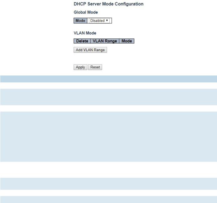
DHCP Server
Mode
This page configures global mode and VLAN mode to enable/disable DHCP server per system and per VLAN.
Object |
Description |
Global Mode |
|
Mode |
Configure the operation mode per system. Possible modes are: |
|
Enabled: Enable DHCP server per system. |
|
Disabled: Disable DHCP server per system. |
VLAN Mode |
|
VLAN Range |
Indicate the VLAN range in which DHCP server is enabled or disabled. The first VLAN ID must be |
|
smaller than or equal to the second VLAN ID. BUT, if the VLAN range contains only 1 VLAN ID, then |
|
you can just input it into either one of the first and second VLAN ID or both. |
|
On the other hand, if you want to disable existed VLAN range, then you can follow the steps. |
|
1. press “Add VLAN Range” to add a new VLAN range. |
|
2. input the VLAN range that you want to disable. |
|
3. choose Mode to be Disabled. |
|
4. press “Save” to apply the change. |
|
Then, you will see the disabled VLAN range is removed from the DHCP Server mode configuration |
|
page. |
Mode |
Indicate the operation mode per VLAN. Possible modes are: |
|
Enabled: Enable DHCP server per VLAN. |
|
Disabled: Disable DHCP server pre VLAN. |
Add VLAN |
Click to apply to add a new VLAN range. |
Range |
|
Apply |
Click to apply changes. |
Reset |
Click to undo any changes made locally and revert to previously saved values. |
TECH SUPPORT: 1.888.678.9427
INS_CNGE24FX12TX12MS[POE] Rev. 2.22.18 PAGE 28

INSTRUCTION MANUAL |
CNGE24FX12TX12MS[POE] |
Excluded IP
This page configures excluded IP addresses. DHCP server will not allocate these excluded IP addresses to DHCP client.
IP Range |
Define the IP range to be excluded IP addresses. The first excluded IP must be smaller than or equal |
|
to the second excluded IP. BUT, if the IP range contains only 1 excluded IP, then you can just input it to |
|
either one of the first and second excluded IP or both. |
Add IP |
Click to add a new IP range. |
Range |
|
Apply |
Click to apple changes. |
Reset |
Click to undo any changes made locally and revert to previously saved values. |
TECH SUPPORT: 1.888.678.9427
INS_CNGE24FX12TX12MS[POE] Rev. 2.22.18 PAGE 29
INSTRUCTION MANUAL |
CNGE24FX12TX12MS[POE] |
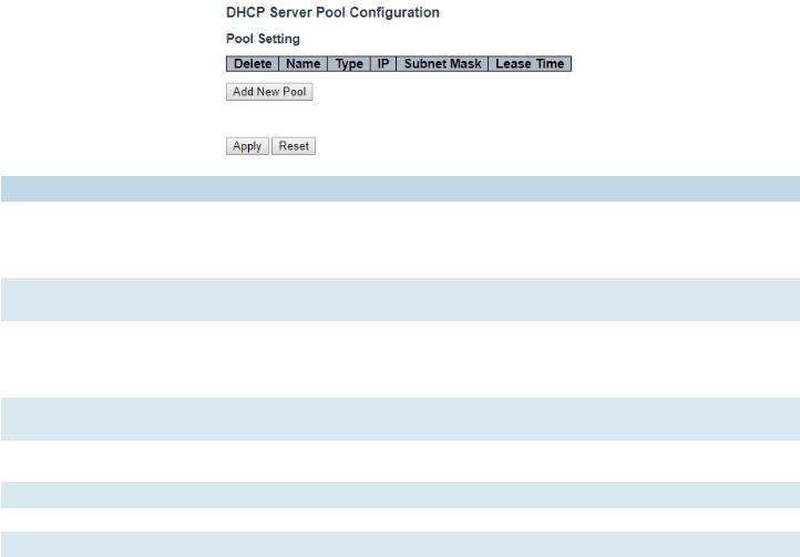
Pool
This page manages DHCP pools. According to the DHCP pool, DHCP server will allocate IP address and deliver configuration parameters to DHCP client.
Object |
Description |
Pool Setting |
Add or delete pools. |
|
Adding a pool and giving a name is to create a new pool with “default” configuration. If you want to |
|
configure all settings including type, IP subnet mask and lease time, you can click the pool name to |
|
go into the configuration page. |
Name |
Configure the pool name that accepts all printable characters, except white space. If you want to |
|
configure the detail settings, you can click the pool name to go into the configuration page. |
Type |
Display which type of the pool is. |
|
Network: the pool defines a pool of IP addresses to service more than one DHCP client. |
|
Host: the pool services for a specific DHCP client identified by client identifier or hardware address. |
|
If “-” is displayed, it means not defined. |
IP |
Display network number of the DHCP address pool. |
|
If “-” is displayed, it means not defined. |
Subnet Mask |
Display subnet mask of the DHCP address pool. |
|
If “-” is displayed, it means not defined. |
Lease Time |
Display lease time of the pool. |
Add New Pool |
Click to add a new DHCP pool. |
Apply |
Click to apply changes. |
Reset |
Click to undo any changes made locally and revert to previously saved values. |
TECH SUPPORT: 1.888.678.9427
INS_CNGE24FX12TX12MS[POE] Rev. 2.22.18 PAGE 30
 Loading...