


INSTALLATION AND OPERATION MANUAL
C(N,W)GE26FX2TX24MS[POE][1] Series
(22) 10/100/1000 BASE-T(X) + (2) GIGABIT COMBO PORTS +
(2) 100/1000 BASE-FX
WITH OPTIONAL POWER OVER ETHERNET (POE+)
This manual serves the following ComNet Model Numbers:
CWGE26FX2TX24MS
CWGE26FX2TX24MSPOE
CNGE26FX2TX24MSPOE1
The ComNet C(N,W)GE26FX2TX24MS[POE][1] Series is a range of extended temperature commercial and industrial grade Managed Ethernet Switches. They provide twenty-four 10/100/1000BASE-T(X) ports with optional IEEE 802.3at PoE two of which are also gigabit combo ports supporting 100/1000FX SFP Modules. A further two 100/1000FX SFP ports are also included. The PoE models provide 320 or 720 watts of PoE power available for distribution across all 24 electrical ports. All SFP ports utilize ComNet SFPs for fiber and connector type and distance.
The C(N,W)GE26FX2TX24MS[POE][1] series are redundant switches offering multiple Ethernet redundancy protocols to protect your applications from network interruptions or temporary malfunctions by redirecting transmission within the network.
INSTALLATION AND OPERATION MANUAL |
C(N,W)GE26FX2TX24MS[POE][1] Series |
Contents
About This Guide |
5 |
Related Documentation |
5 |
About ComNet |
5 |
Website |
5 |
Support |
5 |
Safety |
5 |
Overview |
6 |
Introduction |
6 |
Software Features |
7 |
Hardware Features |
8 |
Hardware Overview |
9 |
Front Panel |
9 |
Rear Panel |
10 |
Rack mount kit assembly |
10 |
Ethernet Cables |
11 |
1000/100BASE-TX/10BASE-T Pin Assignments |
11 |
SFP |
13 |
Console Cable |
13 |
WEB Management |
15 |
Configuration by Web Browser |
15 |
About Web-based Management |
15 |
Basic Setting |
18 |
System Information |
18 |
Admin & Password |
19 |
Auth Method |
20 |
IPv6 Setting |
21 |
IP Setting |
22 |
HTTPS |
23 |
SSH |
23 |
LLDP |
24 |
LLDP Neighbor Information |
25 |
LLDP Neighbor Information |
26 |
Modbus TCP |
28 |
TECH SUPPORT: 1.888.678.9427
INS_C(N,W)GE26FX2TX24MS[POE][1] Series_REV– 17 Nov 2016
PAGE 2
INSTALLATION AND OPERATION MANUAL |
C(N,W)GE26FX2TX24MS[POE][1] Series |
Backup/Restore Configuration |
29 |
Firmware Update |
29 |
DHCP Server |
29 |
Port Setting |
31 |
Port Alias |
33 |
Port Trunk |
34 |
LACP |
36 |
Redundancy |
40 |
Legacy Ring |
41 |
G.8032 - MEP |
42 |
G.8032 - ERPS |
43 |
MSTP |
44 |
STP |
50 |
VLAN |
53 |
VLAN Setting Example |
58 |
Voice VLAN - Configuration |
64 |
Voice VLAN - OUI |
66 |
SNMP |
67 |
Traffic Prioritization |
73 |
Multicast |
87 |
Security Remote Control |
91 |
Security |
92 |
AAA |
96 |
RADIUS Overview |
98 |
Warning |
109 |
System Warning |
110 |
Monitor and Diag |
112 |
Port Statistic |
115 |
System Log Information |
118 |
Cable Diagnostics |
119 |
SFP Monitor |
120 |
Ping |
121 |
Syncronization-PTP |
122 |
PoE Configuration (PoE Models Only) |
124 |
Status |
126 |
Factory Defaults |
127 |
System Reboot |
127 |
TECH SUPPORT: 1.888.678.9427
INS_C(N,W)GE26FX2TX24MS[POE][1] Series_REV– 17 Nov 2016
PAGE 3
INSTALLATION AND OPERATION MANUAL |
C(N,W)GE26FX2TX24MS[POE][1] Series |
Command Line Interface Management |
128 |
About CLI Management |
128 |
Commander Groups |
132 |
Technical Specifications |
146 |
TECH SUPPORT: 1.888.678.9427
INS_C(N,W)GE26FX2TX24MS[POE][1] Series_REV– 17 Nov 2016
PAGE 4
INSTALLATION AND OPERATION MANUAL |
C(N,W)GE26FX2TX24MS[POE][1] Series |
|
|
About This Guide
This guide is intended for different users such as engineers, integrators, developers, IT managers, and technicians.
It assumes that users have some PC competence and are familiar with Microsoft Windows operating systems and web browsers such as Windows Internet Explorer and Mozilla Firefox, as well as have knowledge of the following:
»»Installation of electronic equipment »»Electrical regulations and guidelines
»»Knowledge of Local Area Network technology
Related Documentation
The following documentation is also available: »»CWGE26FX2TX24MS Data sheet
»»CWGE26FX2TX24MSPOE Data sheet »»CNGE26FX2TX24MSPOE1 Data sheet »»SFP Modules Data sheet
About ComNet
ComNet develops and markets the next generation of video solutions for the CCTV, defense, and homeland security markets. At the core of ComNet’s solutions are a variety of high-end video servers and the ComNet IVS software, which provide the industry with a standard platform for analytics and security management systems enabling leading performance, compact and cost effective solutions.
ComNet’s products are available in commercial and rugged form.
Website
For information on ComNet’s entire product line, please visit the ComNet website at http://www.comnet.net
Support
For any questions or technical assistance, please contact your sales person (sales@comnet.net) or the customer service support center (techsupport@comnet.net)
Safety
»»Only ComNet service personnel can service the equipment. Please contact ComNet Technical Support.
»»The equipment should be installed in locations with controlled access, or other means of security, and controlled by persons of authority.
TECH SUPPORT: 1.888.678.9427
INS_C(N,W)GE26FX2TX24MS[POE][1] Series_REV– 17 Nov 2016
PAGE 5
INSTALLATION AND OPERATION MANUAL |
C(N,W)GE26FX2TX24MS[POE][1] Series |
|
|
Overview
Introduction
The C(N,W)GE26FX2TX24MS[POE][1] Series of Gigabit managed redundant ring Ethernet switches provide 22x10/100/1000Base-T(X) ports and two Gigabit combo ports with optional IEEE802.3at PoE and 2x100/1000Base-X SFP ports support Ethernet Redundancy protocol, C-Ring (recovery time < 30ms over 250 units of connection), MSTP (RSTP/STP compatible) and G.8032 ERPS. They can protect your mission-critical applications from network interruptions or temporary malfunctions with their fast recovery technology. The CWGE26FX2TX24MSPOE and CNGE26FX2TX24MSPOE1 models also support Power over Ethernet (PoE+), a system to transmit electrical power up to 30 watts, along with data, to remote devices over standard twisted-pair cable in an Ethernet network.
TECH SUPPORT: 1.888.678.9427
INS_C(N,W)GE26FX2TX24MS[POE][1] Series_REV– 17 Nov 2016
PAGE 6
INSTALLATION AND OPERATION MANUAL |
C(N,W)GE26FX2TX24MS[POE][1] Series |
Software Features
»»C-Ring (recovery time < 30ms over 250 units of connection) »»MSTP (RSTP/STP compatible) for Ethernet Redundancy
»»G.8032 Ethernet Ring protection System (ERPS)
»»Optional 24 ports PSE fully compliant with IEEE802.3at standard, providing up to 30 Watts per port
»»IEEE 1588v2 clock synchronization
»»Provides HTTPS/SSH protocol to enhance network security »»IP-based bandwidth management
»»application-based QoS management »»Device Binding security function
»»IGMP v2/v3 (IGMP snooping support) for filtering multicast traffic »»SNMP v1/v2c/v3 & RMON & 802.1Q VLAN Network Management »»ACL, TACACS+ and 802.1x User Authentication for security
»»9.6K Bytes Jumbo Frame
»»SFP ports support DDM function »»Supports Modbus TCP Protocol
»»Multiple notification for warning of unexpected event
»»Web-based Telnet, Console (CLI), and Windows utility (eConsole) configuration »»LLDP Protocol
»»19 inch rack mountable design
TECH SUPPORT: 1.888.678.9427
INS_C(N,W)GE26FX2TX24MS[POE][1] Series_REV– 17 Nov 2016
PAGE 7
INSTALLATION AND OPERATION MANUAL |
C(N,W)GE26FX2TX24MS[POE][1] Series |
Hardware Features
»»50, 450, or 1000 Watts power supply included (model dependent)
»»Operating Temperature: -10º to +60ºC or -20º to +60ºC (model dependent) »»Storage Temperature: – 40 to 85ºC
»»Operating Humidity: 5% to 95%, non-condensing »»22 × 10/100/1000Base–T(X)
»»2 × 100/1000Base-X SFP & 10/100/1000Base–T(X) COMBO »»2 × 100/1000 Base-X SFP
»»Console Port
»»Dimensions: 43.1 × 34.2 × 4.4 cm (16.97 × 13.47 × 1.73 in)
TECH SUPPORT: 1.888.678.9427
INS_C(N,W)GE26FX2TX24MS[POE][1] Series_REV– 17 Nov 2016
PAGE 8

INSTALLATION AND OPERATION MANUAL |
C(N,W)GE26FX2TX24MS[POE][1] Series |
Hardware Overview
Front Panel
The following table describes the labels on the C(N,W)GE26FX2TX24MS[POE][1] series switches.
Port |
|
|
|
|
Description |
||||
|
|
|
|
|
|
|
|
|
|
Gigabit SFP ports |
|
|
2 x 100/1000Base-X on SFP port |
||||||
|
|
|
|
|
|
|
|
|
|
Combo Ports |
|
|
|
|
2 x 100/1000Base-X SFP & 10/100/1000Base-T(X) Combo |
||||
|
|
|
|
|
|
|
|
|
|
Gigabit Ethernet Ports |
|
|
22 x 10/100/1000Base–T(X) |
||||||
|
|
|
|
|
|
|
|
|
|
Console |
|
|
|
|
Use RS-232 with DB-9 connecter to manage switch. |
||||
|
|
|
|
|
|
|
|
|
|
1 |
3 |
4 |
6 |
|
|||||
|
|
|
|
||||||
|
|
|
|
|
|
|
|
|
|
|
|
|
|
|
|
|
|
|
|
|
|
|
|
|
|
|
|
|
|
8 |
2 |
5 |
7 |
CWGE26FX2TX24MSPOE - Typical Front Panel
1.Console port (DB-9 Female connector)
2.10/100/1000Base-T(X) Gigabit Ethernet ports
3.LED for Odd Numbered Ethernet ports Link/Act status
4.LED for Even Numbered Ethernet ports Link/Act status
5.100/1000Base-X SFP & 10/100/1000Base–T(X) Combo
6.PoE Status LED (PoE Models Only)
7.100/1000Base-X SFP Port
8.Front panel LED Status:
»»LED for PWR The LED lights on when the power module is activated. »»LED for Fault When the fault occurs, the amber LED will be light on.
»»LED for R.M. (Ring master). Indicates that the switch is the Master of the Ring. »»LED for Ring Indicates that the C-Ring is activated.
TECH SUPPORT: 1.888.678.9427
INS_C(N,W)GE26FX2TX24MS[POE][1] Series_REV– 17 Nov 2016
PAGE 9
INSTALLATION AND OPERATION MANUAL |
C(N,W)GE26FX2TX24MS[POE][1] Series |
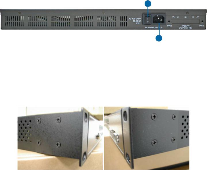
Rear Panel
1
2
The rear panel of CWGE26FX2TX24MSPOE
1.Power Switch
2.Power input for AC 100V~240V / 50~60Hz
Rack mount kit assembly
You can find the rack mount kit and the screws in the packing box. Please assembly the rack mount kit on the switch with screws as shown below:
TECH SUPPORT: 1.888.678.9427
INS_C(N,W)GE26FX2TX24MS[POE][1] Series_REV– 17 Nov 2016
PAGE 10
INSTALLATION AND OPERATION MANUAL |
C(N,W)GE26FX2TX24MS[POE][1] Series |
Ethernet Cables
The C(N,W)GE26FX2TX24MS[POE][1] series switches have standard Ethernet ports. According to the link type, the switches use CAT 3, 4, 5,5e UTP cables to connect to any other network device (PCs, servers, switches, routers, or hubs). Please refer to the following table for cable specifications.
Cable Types and Specifications
Cable |
Type |
Max. Length |
Connector |
|
|
|
|
10BASE-T |
Cat. 3, 4, 5 100-ohm |
UTP 100 m (328 ft) |
RJ-45 |
|
|
|
|
100BASE-TX |
Cat. 5 100-ohm UTP |
UTP 100 m (328 ft) |
RJ-45 |
|
|
|
|
1000BASE-TX |
Cat. 5/Cat. 5e 100-ohm UTP |
UTP 100 m (328ft) |
RJ-45 |
|
|
|
|
1000/100BASE-TX/10BASE-T Pin Assignments
With 1000/100BASE-TX/10BASE-T cable, pins 1 and 2 are used for transmitting data, and pins 3 and 6 are used for receiving data.
|
10/100Base-T(X) PSE RJ-45 port |
||
|
|
|
|
Pin |
|
Assignment |
|
Number |
|||
|
|||
|
|
|
|
#1 |
|
TD+ with PoE Power input + |
|
|
|
|
|
#2 |
|
TD – with PoE Power input + |
|
|
|
|
|
#3 |
|
RD+ with PoE Power input – |
|
|
|
|
|
#6 |
|
RD – with PoE Power input – |
|
|
|
|
|
10/100 Base-T RJ-45 Pin Assignments
Pin Assignment
Number
1TD+
2TD-
3RD+
4Not used
5Not used
6RD-
7Not used
8Not used
1000Base-T PSE RJ-45 port
TECH SUPPORT: 1.888.678.9427
INS_C(N,W)GE26FX2TX24MS[POE][1] Series_REV– 17 Nov 2016
PAGE 11
INSTALLATION AND OPERATION MANUAL |
C(N,W)GE26FX2TX24MS[POE][1] Series |
||
|
|
|
|
|
Pin |
Assignment |
|
|
Number |
|
|
|
|
|
|
|
|
|
|
|
#1 |
BI_DA+ with PoE Power input + |
|
|
|
|
|
|
#2 |
BI_DA – with PoE Power input + |
|
|
|
|
|
|
#3 |
BI_DB+ with PoE Power input – |
|
|
|
|
|
|
#4 |
BI_DC+ |
|
|
|
|
|
|
#5 |
BI_DC- |
|
|
|
|
|
|
#6 |
BI_DB – with PoE Power input – |
|
|
|
|
|
|
#7 |
BI_DD+ |
|
|
|
|
|
|
#8 |
BI_DD- |
|
|
|
|
|
1000 Base-T RJ-45 Pin Assignments
Pin Assignment
Number
1BI_DA+
2BI_DA-
3BI_DB+
4BI_DC+
5BI_DC-
6BI_DB-
7BI_DD+
8BI_DD-
The C(N,W)GE26FX2TX24MS[POE][1] series switches support auto MDI/MDI-X operation. You can use a straight-through cable to connect PC to switch. The following table below shows the 10BASE-T/ 100BASE-TX MDI and MDI-X port pin outs.
10/100 Base-T MDI/MDI-X pins assignment
Pin |
MDI port |
MDI-X port |
|
Number |
|||
|
|
||
|
|
|
|
1 |
TD+(transmit) |
RD+(receive) |
|
|
|
|
|
2 |
TD-(transmit) |
RD-(receive) |
|
|
|
|
|
3 |
RD+(receive) |
TD+(transmit) |
|
|
|
|
|
4 |
Not used |
Not used |
|
|
|
|
|
5 |
Not used |
Not used |
|
|
|
|
|
6 |
RD-(receive) |
TD-(transmit) |
|
|
|
|
|
7 |
Not used |
Not used |
|
|
|
|
|
8 |
Not used |
Not used |
|
|
|
|
TECH SUPPORT: 1.888.678.9427
INS_C(N,W)GE26FX2TX24MS[POE][1] Series_REV– 17 Nov 2016
PAGE 12
INSTALLATION AND OPERATION MANUAL |
|
C(N,W)GE26FX2TX24MS[POE][1] Series |
||
|
1000 Base-T MDI/MDI-X pins assignment |
|||
|
|
|
|
|
|
Pin |
MDI port |
MDI-X port |
|
|
Number |
|
||
|
|
|
|
|
|
|
|
|
|
|
1 |
BI_DA+ |
BI_DB+ |
|
|
|
|
|
|
|
2 |
BI_DA- |
BI_DB- |
|
|
|
|
|
|
|
3 |
BI_DB+ |
BI_DA+ |
|
|
|
|
|
|
|
4 |
BI_DC+ |
BI_DD+ |
|
|
|
|
|
|
|
5 |
BI_DC- |
BI_DD- |
|
|
|
|
|
|
|
6 |
BI_DB- |
BI_DA- |
|
|
|
|
|
|
|
7 |
BI_DD+ |
BI_DC+ |
|
|
|
|
|
|
|
8 |
BI_DD- |
BI_DC- |
|
|
|
|
|
|
Note: “+” and “-” signs represent the polarity of the wires that make up each wire pair.
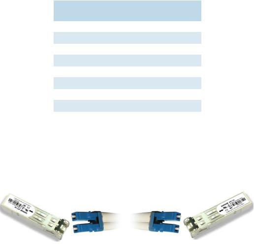
SFP
The Switch has fiber optical ports with SFP connectors. The fiber optical ports are in multi-mode (0 to 550M, 850 nm with 50/125 µm, 62.5/125 µm fiber) and single-mode with LC connector. Please remember that the TX port of Switch A should be connected to the RX port of Switch B.
Switch A |
Switch B |
Console Cable
C(N,W)GE26FX2TX24MS[POE][1] series switches can be managed via a console port located on the front of the switch. The DB-9 cable can be found in the package. You can connect them to PC via a RS-232 cable with DB-9 female connector and the other end (DB-9 male connector) connects to console port of switch.
TECH SUPPORT: 1.888.678.9427
INS_C(N,W)GE26FX2TX24MS[POE][1] Series_REV– 17 Nov 2016
PAGE 13

INSTALLATION AND OPERATION MANUAL |
C(N,W)GE26FX2TX24MS[POE][1] Series |
||
1 |
5 |
5 |
1 |
|
6 |
|
9 |
|
9 |
6 |
|
|
|
DB-9 Male DB-9 Female |
|
||
|
|
|
|
|
|
|
|
|
PC pin out (male) assignment |
RS-232 with DB-9 female |
|
||
|
|
connector |
|
|||
|
|
|
|
|
||
|
|
|
|
|
|
|
|
|
Pin #2 RD |
|
Pin #2 TD |
|
|
|
|
|
|
|
|
|
|
|
Pin #3 TD |
|
Pin #3 RD |
|
|
|
|
|
|
|
|
|
|
|
Pin #5 GD |
|
Pin #5 GD |
|
|
|
|
|
|
|
|
|
|
|
|
|
|
|
|
Pin |
Male Connector |
|
|
Female Connector |
|
|
|
|
|
||||
1 |
Received Line Signal Detect (Received by DTE |
Received Line Signal Detect (Transmitted |
||||
|
Device) |
|
|
from DCE Device) |
|
|
|
|
|
|
|||
2 |
Received Data (Received by DTE Device) |
|
Transmitted Data (Transmitted from DCE |
|||
|
|
|
|
|
Device) |
|
|
|
|
||||
3 |
Transmitted Data (Transmitted from DTE Device) |
Received Data (Received by DCE Device) |
||||
|
|
|
|
|||
4 |
DTE Ready (Transmitted from DTE Device) |
|
DTE Ready (Received by DCE Device) |
|||
|
|
|
|
|
|
|
5 |
Signal Ground |
|
|
Signal Ground |
|
|
|
|
|
|
|||
6 |
DCE Ready (Received by DTE Device) |
|
DCE Ready (Transmitted from DCE Device) |
|||
|
|
|
||||
7 |
Request to Send (Transmitted from DTE Device) |
Clear to Send (Received by DCE Device) |
||||
|
|
|
|
|||
8 |
Clear to Send (Received by DTE Device) |
|
Request to Send (Transmitted from DCE |
|||
|
|
|
|
|
Device) |
|
|
|
|
|
|||
9 |
Ring Indicator (Received by DTE Device) |
|
Ring Indicator (Transmitted from DCE |
|||
|
|
|
|
|
Device) |
|
|
|
|
|
|
|
|
TECH SUPPORT: 1.888.678.9427
INS_C(N,W)GE26FX2TX24MS[POE][1] Series_REV– 17 Nov 2016
PAGE 14
INSTALLATION AND OPERATION MANUAL |
C(N,W)GE26FX2TX24MS[POE][1] Series |
WEB Management
Attention: While installing and upgrading firmware, please remove physical loop connection first. DO NOT power off equipment while the firmware is upgrading!
Configuration by Web Browser
This section introduces the configuration by Web browser.
About Web-based Management
An embedded HTML web site resides in flash memory on the CPU board. It contains advanced management features and allows you to manage the switch from anywhere on the network through a standard web browser such as Microsoft Internet Explorer.
The Web-Based Management function supports Internet Explorer 5.0 or later. It is based on Java Applets with an aim to reduce network bandwidth consumption, enhance access speed and present an easy viewing screen.
Note: By default, IE5.0 or later version does not allow Java Applets to open sockets. You need to intentionally modify the browser setting in order to enable Java Applets to use network ports.
Preparing for Web Management
IP Address: 192.168.10.1
Subnet Mask: 255.255.255.0
Default Gateway: 192.168.10.254
User Name: admin
Password: admin
TECH SUPPORT: 1.888.678.9427
INS_C(N,W)GE26FX2TX24MS[POE][1] Series_REV– 17 Nov 2016
PAGE 15

INSTALLATION AND OPERATION MANUAL |
C(N,W)GE26FX2TX24MS[POE][1] Series |
System Login
1.Launch Internet Explorer.
2.Type http:// and the IP address of the switch. Press “Enter”.
3.The login screen appears.
Login screen
4.Key in the username and password. The default username and password is admin.
5.Press OK button, then the main interface of the Web-based management appears.
TECH SUPPORT: 1.888.678.9427
INS_C(N,W)GE26FX2TX24MS[POE][1] Series_REV– 17 Nov 2016
PAGE 16

INSTALLATION AND OPERATION MANUAL |
C(N,W)GE26FX2TX24MS[POE][1] Series |
Main Interface
Main interface
TECH SUPPORT: 1.888.678.9427
INS_C(N,W)GE26FX2TX24MS[POE][1] Series_REV– 17 Nov 2016
PAGE 17

INSTALLATION AND OPERATION MANUAL |
C(N,W)GE26FX2TX24MS[POE][1] Series |
Basic Setting
System Information
The switch system information is provided here.
|
System Information interface |
|
|
Label |
Description |
|
|
System Name |
An administratively assigned name for this managed node. By convention, this is the |
|
node’s fully-qualified domain name. A domain name is a text string drawn from the |
|
alphabet (A-Za-z), digits (0-9), minus sign (-). No space characters are permitted as |
|
part of a name. The first character must be an alpha character. And the first or last |
|
character must not be a minus sign. The allowed string length is 0 to 255. |
|
|
System Description |
The device Description. |
|
|
System Location |
The physical location of this node(e.g., telephone closet, 3rd floor). The allowed |
|
string length is 0 to 255, and the allowed content is the ASCII characters from 32 to |
|
126. |
|
|
System Contact |
The textual identification of the contact person for this managed node, together |
|
with information on how to contact this person. The allowed string length is 0 to |
|
255, and the allowed content is the ASCII characters from 32 to 126. |
|
|
Save |
Click to save changes. |
|
|
Reset |
Click to undo any changes made locally and revert to previously saved values. |
|
|
TECH SUPPORT: 1.888.678.9427
INS_C(N,W)GE26FX2TX24MS[POE][1] Series_REV– 17 Nov 2016
PAGE 18

INSTALLATION AND OPERATION MANUAL |
C(N,W)GE26FX2TX24MS[POE][1] Series |
Admin & Password
This page allows you to configure the system password required to access the web pages or log in from CLI.
Label |
Description |
|
|
Old Password |
Enter the current system password. If this is incorrect, the new password will not be set. |
|
|
New Password |
The system password. The allowed string length is 0 to 31, and the allowed content is |
|
the ASCII characters from 32 to 126. |
|
|
Confirm |
Re-type the new password. |
password |
|
|
|
Save |
Click to save changes. |
|
|
TECH SUPPORT: 1.888.678.9427
INS_C(N,W)GE26FX2TX24MS[POE][1] Series_REV– 17 Nov 2016
PAGE 19
INSTALLATION AND OPERATION MANUAL |
C(N,W)GE26FX2TX24MS[POE][1] Series |
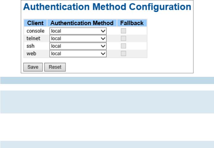
Auth Method
This page allows you to configure how a user is authenticated when he logs into the switch via one of the management client interfaces.
Label |
Description |
|
|
Client |
The management client for which the configuration below applies. |
|
|
Authentication |
Authentication Method can be set to one of the following values: |
Method |
none: authentication is disabled and login is not possible. |
|
local: use the local user database on the switch for authentication. |
|
radius: use a remote RADIUS server for authentication. |
|
|
Fallback |
Enable fallback to local authentication by checking this box. |
|
If none of the configured authentication servers are alive, the local user database is |
|
used for authentication. |
|
This is only possible if the Authentication Method is set to a value other than ‘none’ or |
|
‘local’. |
|
|
Save |
Click to save changes. |
|
|
Reset |
Click to undo any changes made locally and revert to previously saved values. |
|
|
TECH SUPPORT: 1.888.678.9427
INS_C(N,W)GE26FX2TX24MS[POE][1] Series_REV– 17 Nov 2016
PAGE 20
INSTALLATION AND OPERATION MANUAL |
C(N,W)GE26FX2TX24MS[POE][1] Series |
IPv6 Setting
Configure the switch-management IPv6 information on this page.
Label |
Description |
|
|
Auto |
Enable IPv6 auto-configuration by checking this box. If the system cannot obtain the |
Configuration |
stateless address in time, the configured IPv6 settings will be used. The router may |
|
delay responding to a router solicitation for a few seconds, the total time needed to |
|
complete auto-configuration can be significantly longer. |
|
|
Address |
Provide the IPv6 address of this switch. IPv6 address is in 128-bit records represented |
|
as eight fields of up to four hexadecimal digits with a colon separating each field (:). For |
|
example, ‘fe80::215:c5ff:fe03:4dc7’. The symbol ‘::’ is a special syntax that can be used |
|
as a shorthand way of representing multiple 16-bit groups of contiguous zeros; but it |
|
can appear only once. It can also represent a legally valid IPv4 address. For example, |
|
‘::192.1.2.34’. |
|
|
Prefix |
Provide the IPv6 Prefix of this switch. The allowed range is 1 to 128. |
|
|
Router |
Provide the IPv6 gateway address of this switch. IPv6 address is in 128-bit records |
|
represented as eight fields of up to four hexadecimal digits with a colon separating |
|
each field (:). For example, ‘fe80::215:c5ff:fe03:4dc7’. The symbol ‘::’ is a special |
|
syntax that can be used as a shorthand way of representing multiple 16-bit groups of |
|
contiguous zeros; but it can appear only once. It can also represent a legally valid IPv4 |
|
address. . For example, ‘::192.1.2.34’. |
|
|
Save |
Click to save changes. |
|
|
Reset |
Click to undo any changes made locally and revert to previously saved values. |
|
|
TECH SUPPORT: 1.888.678.9427
INS_C(N,W)GE26FX2TX24MS[POE][1] Series_REV– 17 Nov 2016
PAGE 21

INSTALLATION AND OPERATION MANUAL |
C(N,W)GE26FX2TX24MS[POE][1] Series |
IP Setting
Configure the switch-managed IP information on this page.
Label |
Description |
|
|
DHCP Client |
Enable the DHCP client by checking this box. If DHCP fails and the configured IP |
|
address is zero, DHCP will retry. If DHCP fails and the configured IP address is non- |
|
zero, DHCP will stop and the configured IP settings will be used. The DHCP client will |
|
announce the configured System Name as hostname to provide DNS lookup. |
|
|
IP Address |
Assign the IP address that the network is using. If DHCP client function is enabling, |
|
you do not need to assign the IP address. The network DHCP server will assign the IP |
|
address for the switch and it will be display in this column. The default IP is 192.168.10.1 |
|
|
IP Mask |
Assign the subnet mask of the IP address. If DHCP client function is enabling, you do |
|
not need to assign the subnet mask |
|
|
IP Router |
Assign the network gateway for the switch. The default gateway is 192.168.10.254 |
|
|
VLAN ID |
Provide the managed VLAN ID. The allowed range is 1 through 4095. |
|
|
SNTP Server |
Provide the IP address of the SNTP Server in dotted decimal notation. |
|
|
Save |
Click to save changes. |
|
|
Reset |
Click to undo any changes made locally and revert to previously saved values. |
|
|
TECH SUPPORT: 1.888.678.9427
INS_C(N,W)GE26FX2TX24MS[POE][1] Series_REV– 17 Nov 2016
PAGE 22

INSTALLATION AND OPERATION MANUAL |
C(N,W)GE26FX2TX24MS[POE][1] Series |
HTTPS
Label |
Description |
|
|
Mode |
Indicates the HTTPS mode operation. When the current connection is HTTPS, to apply |
|
HTTPS disabled mode operation will automatically redirect web browser to an HTTP |
|
connection. Possible modes are: |
|
Enabled: Enable HTTPS mode operation. |
|
Disabled: Disable HTTPS mode operation. |
|
|
Save |
Click to save changes. |
|
|
Reset |
Click to undo any changes made locally and revert to previously saved values. |
|
|
SSH
Label |
Description |
|
|
Mode |
Indicates the SSH mode operation. Possible modes are: |
|
Enabled: Enable SSH mode operation. |
|
Disabled: Disable SSH mode operation. |
|
|
Save |
Click to save changes. |
|
|
Reset |
Click to undo any changes made locally and revert to previously saved values. |
|
|
TECH SUPPORT: 1.888.678.9427
INS_C(N,W)GE26FX2TX24MS[POE][1] Series_REV– 17 Nov 2016
PAGE 23

INSTALLATION AND OPERATION MANUAL |
C(N,W)GE26FX2TX24MS[POE][1] Series |
LLDP
|
LLDP Configuration |
This page allows the user to inspect and configure the current LLDP port settings. |
|
|
|
Label |
Description |
|
|
Port |
The switch port number of the logical LLDP port. |
|
|
Mode |
Select LLDP mode. |
|
Disabled The switch will not send out LLDP information, and will drop LLDP information |
|
received from neighbors. |
|
Enabled The switch will send out LLDP information, and will analyze LLDP information |
|
received from neighbors. |
|
|
TECH SUPPORT: 1.888.678.9427
INS_C(N,W)GE26FX2TX24MS[POE][1] Series_REV– 17 Nov 2016
PAGE 24
INSTALLATION AND OPERATION MANUAL |
C(N,W)GE26FX2TX24MS[POE][1] Series |
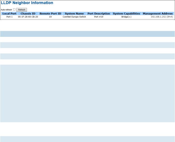
LLDP Neighbor Information
This page provides a status overview for all LLDP neighbors. The displayed table contains a row for each port on which an LLDP neighbor is detected. The columns hold the following information:
|
LLDP Neighbor Information |
|
|
Label |
Description |
|
|
Local Port |
The port on which the LLDP frame was received. |
|
|
Chassis ID |
The Chassis ID is the identification of the neighbor’s LLDP frames. |
|
|
Remote Port ID |
The Remote Port ID is the identification of the neighbor port. |
|
|
System Name |
System Name is the name advertised by the neighbor unit. |
|
|
Port Description |
Port Description is the port description advertised by the neighbor unit. |
|
|
System |
System Capabilities describes the neighbor unit’s capabilities. The possible capabilities |
Capabilities |
are: |
|
1. Other |
|
2. Repeater |
|
3. Bridge |
|
4. WLAN Access Point |
|
5. Router |
|
6. Telephone |
|
7. DOCSIS cable device |
|
8. Station only |
|
9. Reserved |
|
When a capability is enabled, the capability is followed by (+). If the capability is |
|
disabled, the capability is followed by (-). |
|
|
Management |
Management Address is the neighbor unit’s address that is used for higher layer |
Address |
entities to assist the discovery by the network management. This could for instance |
|
hold the neighbor’s IP address. |
|
|
Refresh |
Click to refresh the page immediately. |
|
|
Auto-Refresh |
Check this box to enable an automatic refresh of the page at regular intervals. |
|
|
TECH SUPPORT: 1.888.678.9427
INS_C(N,W)GE26FX2TX24MS[POE][1] Series_REV– 17 Nov 2016
PAGE 25

INSTALLATION AND OPERATION MANUAL |
C(N,W)GE26FX2TX24MS[POE][1] Series |
LLDP Neighbor Information
This page provides an overview of all LLDP traffic.
Two types of counters are shown. Global counters are counters that refer to the whole stack, switch, while local counters refer to counters for the currently selected switch.
|
Port Statistics |
|
Global Counters |
|
|
Label |
Description |
|
|
Neighbor entries were last |
Shows the time for when the last entry was last deleted or added. It is |
changed at |
also shows the time elapsed since last change was detected. |
|
|
Total Neighbors Entries Added |
Shows the number of new entries added since switch reboot. |
|
|
Total Neighbors Entries Deleted |
Shows the number of new entries deleted since switch reboot. |
|
|
Total Neighbors Entries Dropped |
Shows the number of LLDP frames dropped due to that the entry |
|
table was full. |
|
|
Total Neighbors Entries Aged Out |
Shows the number of entries deleted due to Time-To-Live expiring. |
|
|
TECH SUPPORT: 1.888.678.9427
INS_C(N,W)GE26FX2TX24MS[POE][1] Series_REV– 17 Nov 2016
PAGE 26
INSTALLATION AND OPERATION MANUAL |
C(N,W)GE26FX2TX24MS[POE][1] Series |
|
|
Local Counters |
|
|
|
|
Label |
Description |
|
|
|
|
Local Port |
The port on which LLDP frames are received or transmitted. |
|
|
|
|
Tx Frames |
The number of LLDP frames transmitted on the port. |
|
|
|
|
Rx Frames |
The number of LLDP frames received on the port. |
|
|
|
|
Rx Errors |
The number of received LLDP frames containing some kind of error. |
|
|
|
|
Frames |
If an LLDP frame is received on a port, and the switch’s internal table has run full, the |
|
Discarded |
LLDP frame is counted and discarded. This situation is known as “Too Many Neighbors” |
|
|
in the LLDP standard. LLDP frames require a new entry in the table when the Chassis ID |
|
|
or Remote Port ID is not already contained within the table. Entries are removed from |
|
|
the table when a given port links down, an LLDP shutdown frame is received, or when |
|
|
the entry ages out. |
|
|
|
|
TLVs Discarded |
Each LLDP frame can contain multiple pieces of information, known as TLVs (TLV is |
|
|
short for “Type Length Value”). If a TLV is malformed, it is counted and discarded. |
|
|
|
|
TLVs |
The number of well-formed TLVs, but with an unknown type value. |
|
Unrecognized |
|
|
|
|
|
Org. Discarded |
The number of organizationally TLVs received. |
|
|
|
|
Age-Outs |
Each LLDP frame contains information about how long time the LLDP information is |
|
|
valid (age-out time). If no new LLDP frame is received within the age out time, the LLDP |
|
|
information is removed, and the Age-Out counter is incremental. |
|
|
|
|
Refresh |
Click to refresh the page immediately. |
|
|
|
|
Clear |
Clears the local counters. All counters (including global counters) are cleared upon |
|
|
reboot. |
|
|
|
|
Auto-Refresh |
Check this box to enable an automatic refresh of the page at regular intervals. |
|
|
|
|
TECH SUPPORT: 1.888.678.9427
INS_C(N,W)GE26FX2TX24MS[POE][1] Series_REV– 17 Nov 2016
PAGE 27
INSTALLATION AND OPERATION MANUAL |
C(N,W)GE26FX2TX24MS[POE][1] Series |
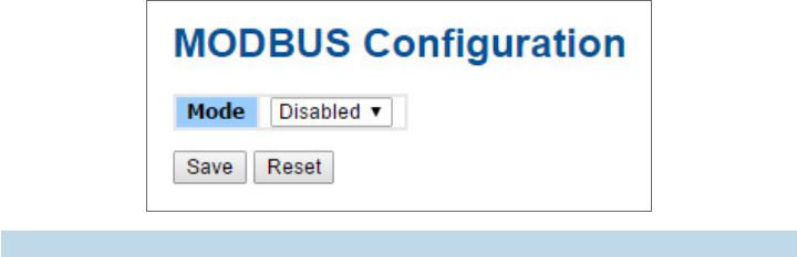
Modbus TCP
This page shows Modbus TCP support of the switch. (For more information regarding Modbus,
please visit http://www.modbus.org/)
Label |
Description |
|
|
Mode |
Shows the existing status of the Modbus TCP function |
|
|
TECH SUPPORT: 1.888.678.9427
INS_C(N,W)GE26FX2TX24MS[POE][1] Series_REV– 17 Nov 2016
PAGE 28
INSTALLATION AND OPERATION MANUAL |
C(N,W)GE26FX2TX24MS[POE][1] Series |
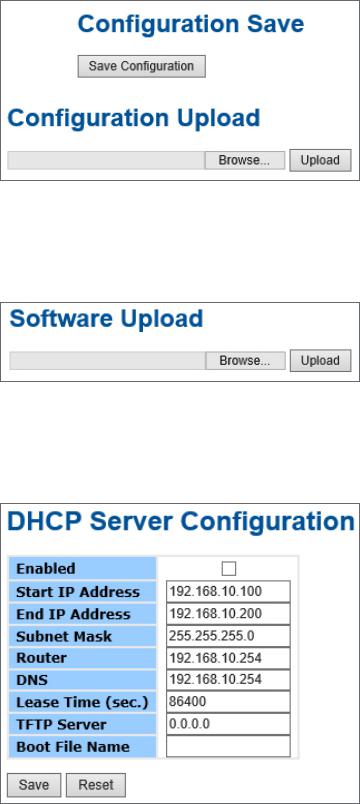
Backup/Restore Configuration
You can save/view or load the switch configuration. The configuration file is in XML format with a hierarchy of tags:
Firmware Update
This page facilitates an update of the firmware controlling the switch.
DHCP Server
Setting
The system provides with DHCP server function. Enable the DHCP server function, the switch system will be a DHCP server.
TECH SUPPORT: 1.888.678.9427
INS_C(N,W)GE26FX2TX24MS[POE][1] Series_REV– 17 Nov 2016
PAGE 29

INSTALLATION AND OPERATION MANUAL |
C(N,W)GE26FX2TX24MS[POE][1] Series |
DHCP Dynamic Client List
When the DHCP server function is activated, the system will collect the DHCP client information and display in here.
DHCP Client List
You can assign the specific IP address which is in the assigned dynamic IP range to the specific port. When the device is connecting to the port and asks for dynamic IP assigning, the system will assign the IP address that has been assigned before in the connected device.
TECH SUPPORT: 1.888.678.9427
INS_C(N,W)GE26FX2TX24MS[POE][1] Series_REV– 17 Nov 2016
PAGE 30
 Loading...