


INSTALLATION AND OPERATION MANUAL
CNGE12MS
12-Port Managed Gigabit Switch
v1.2 Sept 2012
The ComNet™ CNGE12MS is a 12-port Managed Ethernet Switch designed to reliably operate in harsh, environmentally challenging applications. It features four (4) 1000BASE-X and eight (8) gigabit combo ports. The eight combo ports are 10/100/1000Mbps configurable for either CAT5-e copper, or multimode or singlemode optical fiber by the use of optional ComNet SFPs*. Exclusive to ComNet is C-Ring, a feature that protects the network from interruptions or temporary malfunctions with fast recovery technology. Legacy ring allows the switch to be used in an existing ring of ComNet X-Ring enabled switches. Redundant DC inputs are included for uninterrupted operation in the event of a power supply failure. The electrical ports support the 10/100/1000Mbps Ethernet IEEE802.3 protocol, and auto-negotiating and auto-MDi/MDiX features are provided. These network-managed layer 2 switches are optically and electrically compatible with any IEEE802.3 compliant Ethernet device. The CNGE12MS is DIN-rail or wall-mountable.
Rev. 12.17.12
INSTALLATION AND OPERATION MANUAL |
CNGE12MS |
Contents
Regulatory Compliance Statement |
3 |
Warranty |
3 |
Disclaimer |
3 |
Safety Information |
3 |
Overview |
4 |
Introduction |
4 |
Software Features |
5 |
Hardware Features |
5 |
Hardware Installation |
6 |
Installing the Switch on DIN-Rail |
6 |
Wall Mounting Installation |
8 |
Hardware Overview |
9 |
Front Panel |
9 |
Front Panel LEDs |
10 |
Top View Panel |
10 |
Rear Panel |
11 |
Cables |
12 |
Ethernet Cables |
12 |
SFP |
14 |
Console Cable |
14 |
WEB Management |
16 |
Command Line Interface Management |
85 |
About CLI Management |
85 |
Technical Specifications |
98 |
Tech Support: 1.888.678.9427
INS_CNGE12MS_REV–
09/12/12 PAGE 2
INSTALLATION AND OPERATION MANUAL |
CNGE12MS |
|
|
Regulatory Compliance Statement
Product(s) associated with this publication complies/comply with all applicable regulations. Please refer to the Technical Specifications section for more details.
Warranty
ComNet warrants that all ComNet products are free from defects in material and workmanship for a specified warranty period from the invoice date for the life of the installation. ComNet will repair or replace products found by ComNet to be defective within this warranty period, with shipment expenses apportioned by ComNet and the distributor. This warranty does not cover product modifications or repairs done by persons other than ComNet-approved personnel, and this warranty does not apply to ComNet products that are misused, abused, improperly installed, or damaged by accidents.
Please refer to the Technical Specifications section for the actual warranty period(s) of the product(s) associated with this publication.
Disclaimer
Information in this publication is intended to be accurate. ComNet shall not be responsible for its use or infringements on third-parties as a result of its use. There may occasionally be unintentional errors on this publication. ComNet reserves the right to revise the contents of this publication without notice.
Safety Information
»»Only ComNet service personnel can service the equipment. Please contact ComNet Technical Support.
»»The equipment should be installed in locations with controlled access, or other means of security, and controlled by persons of authority.
Tech Support: 1.888.678.9427
INS_CNGE12MS_REV–
09/12/12 PAGE 3
INSTALLATION AND OPERATION MANUAL |
CNGE12MS |
|
|
Overview
Introduction
The CNGE12MS is powerful managed Ethernet switch that has many features. These switches can work under a wide temperature range, dusty environment and humidity condition They can be managed by Windows Utility, WEB, TELNET and Console or other third-party SNMP software as well.
Tech Support: 1.888.678.9427
INS_CNGE12MS_REV–
09/12/12 PAGE 4
INSTALLATION AND OPERATION MANUAL |
CNGE12MS |
Software Features
»»Redundant Ethernet Ring (Recovery time < 30ms over 250 unit connection) »»Supports Ring Coupling, Dual Homing, RSTP over Ring
»»Supports SNMPv1/v2c/v3 & RMON & Port base/IEEE 802.1Q VLAN Network Management »»Event notification by Email, SNMP trap and Relay Output
»»Windows Utility, Web-based, Telnet and Console (CLI) configuration »»Enable/disable ports, MAC based port security
»»Port based network access control (IEEE 802.1x)
»»VLAN (IEEE 802.1q) to segregate and secure network traffic »»Radius centralized password management
»»SNMPv3 encrypted authentication and access security »»RSTP (IEEE 802.1w)
»»Quality of Service (IEEE 802.1p) for real-time traffic
»»VLAN (IEEE 802.1q) with double tagging and GVRP supported »»IGMP Snooping for multicast filtering
»»Port configuration, status, statistics, mirroring, security »»Remote Monitoring (RMON)
Hardware Features
»»Redundant dual DC power inputs
»»Wide Operating Temperature Range: -40º to 75ºC »»Storage Temperature: -40º to 85ºC
»»Operating Humidity: 5% to 95%, non-condensing »»Casing: Aluminum
»»8 x Gigabit combo ports with 100/1000BASE-X SFP & 10/100/1000BASE–T(X) »»4 x 1000BASE-X SFP
»»Console Port
»»Dimensions (W × D × H) 96.4 × 108.5 × 154 mm (3.8 × 4.2.7 × 6.06 in)
Tech Support: 1.888.678.9427
INS_CNGE12MS_REV–
09/12/12 PAGE 5

INSTALLATION AND OPERATION MANUAL |
CNGE12MS |
Hardware Installation
Installing the Switch on DIN-Rail
Metal Spring
Each switch has a Din-Rail kit on the rear panel. The DIN-Rail kit affixes the switch to the DIN-Rail. It is easy to install the switch on the Din-Rail:
Tech Support: 1.888.678.9427
INS_CNGE12MS_REV–
09/12/12 PAGE 6

INSTALLATION AND OPERATION MANUAL |
CNGE12MS |
Mount Series on DIN-Rail
Step 1: Tilt the switch and mount the metal spring to DIN-Rail.
Step 2: Push the switch toward the DIN-Rail until you hear the spring snap into place
.
Tech Support: 1.888.678.9427
INS_CNGE12MS_REV–
09/12/12 PAGE 7

INSTALLATION AND OPERATION MANUAL |
CNGE12MS |
Wall Mounting Installation
Each switch has another installation method for users to fix the switch. A wall mount panel can be found in the package. The following steps show how to mount the switch on the wall:
Mounting the CNGE12MS on a Wall
Step 1: Remove Din-Rail kit.
Step 2: Use the 6 included screws to attach the wall mount panel as shown in the diagram below.
The screw specifications are shown in the following two pictures. In order to prevent switches from being damaged, the screws should not be larger than the size that used in CNGE12MS switch.
Tech Support: 1.888.678.9427
INS_CNGE12MS_REV–
09/12/12 PAGE 8
INSTALLATION AND OPERATION MANUAL |
CNGE12MS |
Hardware Overview
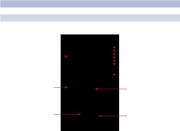
Front Panel
Port |
Description |
|
SFP ports |
4 |
1000BASE-X on SFP port |
Combo Port |
8 |
100/1000BASE-X on SFP port and 8 10/100/1000BASE-T(X) |
Console |
Use RS-232 with RJ-45 connector to manage switch. |
|
12 |
|
|
|
|
1 |
2 |
3 |
4 |
5 |
|
|
|
|||||||||
|
|
|
|
|
|
|||||
|
|
|
|
|
|
|
||||
|
|
|
|
|
|
|
||||
|
|
|
|
|
|
|
|
|||
|
|
|
|
|
|
|
|
|||
|
|
|
|
|
|
|
|
|
||
|
|
|
|
|
|
|
|
|
6 |
|
|
|
|
|
|
7 |
|
|
|
|
|
|
|
|
|
|
|
|
|
|
|
|
|
|
|
|
|
|
11 |
8 |
|
10 |
9 |
|
CNGE12MS
1.LED for PWR. With PWR UP, the green LED will be light on
2.LED for PWR1
3.LED for PWR2
4.LED for R.M (Ring master). When the LED light is on, it means that this switch is the master.
5.LED for Ring. When the led light is on, it means that C-Ring is activated.
6.LED for Fault. When the light on, it means Power failure or Port down/fail.
7.Console port (RJ-45)
8.100/1000BASE-X SFP ports (combo)
9.LED for SFP ports link status.
10.LED for Ethernet ports link status.
11.10/100/1000BASE-T(X) ports (combo)
12.1000 BASE-X SFP ports
Tech Support: 1.888.678.9427
INS_CNGE12MS_REV–
09/12/12 PAGE 9

INSTALLATION AND OPERATION MANUAL |
CNGE12MS |
||
Front Panel LEDs |
|
|
|
LED |
Color |
Status |
Description |
PWR |
Green |
On |
DC power module up |
PW1 |
Green |
On |
DC power module 1 activated. |
PW2 |
Green |
On |
DC Power module 2 activated. |
R.M |
Green |
On |
Ring Master. |
Ring |
Green |
On |
Ring enabled. |
|
|
Slowly blinking |
Ring has only One link. (lack of one link to build the |
|
|
|
ring.) |
|
|
Fast blinking |
Ring is working normally. |
Fault |
Amber |
On |
Fault relay. Power failure or Port down/fail. |
Gigabit Ethernet ports |
|
|
|
LNK/ACT |
Green |
Blinking |
Data transmitted. |
Full Duplex |
Amber |
On |
Port works under full duplex. |
Gigabit SFP ports |
|
|
|
LNK/ACT |
Green |
Blinking |
Data transmitted. |
|
|
On |
Port link up. |
Top View Panel
The bottom panel component of CNGE12MS is shown as below:
1.Terminal block includes: PWR1, PWR2 (12-48V DC)
2.Ground wire
Tech Support: 1.888.678.9427
INS_CNGE12MS_REV–
09/12/12 PAGE 10
INSTALLATION AND OPERATION MANUAL |
CNGE12MS |
Rear Panel
The rear panel components of CNGE12MS are shown below:
1.Screw holes for wall mount kit.
2.Din-Rail kit
1
2
1
Tech Support: 1.888.678.9427
INS_CNGE12MS_REV–
09/12/12 PAGE 11

INSTALLATION AND OPERATION MANUAL |
CNGE12MS |
Cables
Ethernet Cables
The CNGE12MS switch has standard Ethernet ports. According to the link type, the switch uses CAT3, CAT4, CAT5 or CAT5-e UTP cables to connect to any other network device (PCs, servers, switches, routers, or hubs). Please refer to the following table for cable specifications.
Cable |
Type |
Max. Length |
Connector |
10BASE-T |
CAT3, CAT4, CAT5 100Ω |
UTP 100m (328ft) |
RJ-45 |
100BASE-TX |
CAT5 100Ω UTP |
UTP 100m (328ft) |
RJ-45 |
1000BASE-TX |
CAT5/CAT5-e 100Ω UTP |
UTP 100m (328ft) |
RJ-45 |
Cable Types and Specifications
10/100BASE-T(X) Pin Assignments
With 10/100BASE-T(X) cable, pins 1 and 2 are used for transmitting data, and pins 3 and 6 are used for receiving data.
Pin Number |
Assignment |
1 |
TD+ |
2 |
TD- |
3 |
RD+ |
4 |
Not used |
5 |
Not used |
6 |
RD- |
7 |
Not used |
8 |
Not used |
10/100 BASE-T RJ-45 Pin Assignments
Tech Support: 1.888.678.9427
INS_CNGE12MS_REV–
09/12/12 PAGE 12

INSTALLATION AND OPERATION MANUAL |
CNGE12MS |
Pin Number |
Assignment |
1 |
BI_DA+ |
2 |
BI_DA- |
3 |
BI_DB+ |
4 |
BI_DC+ |
5 |
BI_DC- |
6 |
BI_DB- |
7 |
BI_DD+ |
8 |
BI_DD- |
1000 BASE-T RJ-45 Pin Assignments
The CNGE12MS switch supports auto MDI/MDI-X operation. You can use a straight-through cable to connect a PC to the switch. The table below shows the 10/100BASE-T(X) MDI and MDI-X port pin outs.
Pin Number |
MDI port |
MDI-X port |
1 |
TD+(transmit) |
RD+(receive) |
2 |
TD-(transmit) |
RD-(receive) |
3 |
RD+(receive) |
TD+(transmit) |
4 |
Not used |
Not used |
5 |
Not used |
Not used |
6 |
RD-(receive) |
TD-(transmit) |
7 |
Not used |
Not used |
8 |
Not used |
Not used |
10/100 BASE-T MDI/MDI-X pins assignment |
||
Pin Number |
MDI port |
MDI-X port |
1 |
BI_DA+ |
BI_DB+ |
2 |
BI_DA- |
BI_DB- |
3 |
BI_DB+ |
BI_DA+ |
4 |
BI_DC+ |
BI_DD+ |
5 |
BI_DC- |
BI_DD- |
6 |
BI_DB- |
BI_DA- |
7 |
BI_DD+ |
BI_DC+ |
8 |
BI_DD- |
BI_DC- |
1000 BASE-T MDI/MDI-X pins assignment
Note: “+” and “-” signs represent the polarity of the wires that make up each wire pair.
Tech Support: 1.888.678.9427
INS_CNGE12MS_REV–
09/12/12 PAGE 13
INSTALLATION AND OPERATION MANUAL |
CNGE12MS |
SFP
The switch has fiber optic ports with SFP connectors. The fiber optical ports are available with multi-mode and single-mode fiber with various distance and connector types. Please remember that the TX port of Switch A should be connected to the RX port of Switch B.
Switch-A |
Switch-B |
Console Cable
CNGE12MS switch can be managed by the console port. The DB-9 to RJ-45 cable can be found in the package. You can connect them to the PC via a RS-232 cable with DB-9 female connector and the other end (RJ-45 connector) connects to console port of switch.
PC pin |
RS-232 with |
|
out (male) |
DB9 female |
DB9 to RJ 45 |
assignment |
connector |
|
Pin #2 RD |
Pin #2 TD |
Pin #2 |
Pin #3 TD |
Pin #3 RD |
Pin #3 |
Pin #5 GD |
Pin #5 GD |
Pin #5 |
Tech Support: 1.888.678.9427
INS_CNGE12MS_REV–
09/12/12 PAGE 14

INSTALLATION AND OPERATION MANUAL |
CNGE12MS |
5 |
1 |
9 |
6 |
|
DB9 Male |
1 |
5 |
6 |
9 |
DB9 Female
Pin Male Connector
1Received Line Signal Detect (Received by DTE Device)
2Received Data (Received by DTE Device)
3Transmitted Data (Transmitted from DTE Device)
4DTE Ready (Transmitted from DTE Device)
5Signal Ground
6DCE Ready (Received by DTE Device)
7Request to Send (Transmitted from DTE Device)
8Clear to Send (Received by DTE Device)
9Ring Indicator (Received by DTE Device)
Female Connector
Received Line Signal Detect (Transmitted from DCE Device)
Transmitted Data (Transmitted from DCE Device)
Received Data (Received by DCE Device) DTE Ready (Received by DCE Device) Signal Ground
DCE Ready (Transmitted from DCE Device) Clear to Send (Received by DCE Device)
Request to Send (Transmitted from DCE Device)
Ring Indicator (Transmitted from DCE Device)
Tech Support: 1.888.678.9427
INS_CNGE12MS_REV–
09/12/12 PAGE 15

INSTALLATION AND OPERATION MANUAL |
CNGE12MS |
WEB Management
Attention: While installing and upgrading firmware, please remove physical loop connection first. DO NOT power off equipment while the firmware is upgrading!
Configuration by Web Browser
This section details configuration through the Web browser.
About Web-based Management
An embedded HTML web site resides in the flash memory on the CPU board. It contains advanced management features and allows you to manage the switch from anywhere on the network through a standard web browser such as Microsoft Internet Explorer.
The Web-Based Management function supports Internet Explorer 5.0 or later. It is based on Java Applets with an aim to reduce network bandwidth consumption, enhance access speed and present an easy viewing screen.
Note: By default, IE5.0 or later version does not allow Java Applets to open sockets. You need to explicitly modify the browser setting in order to enable Java Applets to use network ports.
Preparing for Web Management
The default value is as below:
IP Address: 192.168.10.1
Subnet Mask: 255.255.255.0
Default Gateway: 192.168.10.254
User Name: admin
Password: admin
System Login
1.Launch Internet Explorer.
2.Type http://192.168.10.1. Press Enter.
3.The login screen appears.
4.Key in the username and password. The default username and password is admin.
5.Select Enter or OK button, then the main interface of the Web-based management appears.
Tech Support: 1.888.678.9427
INS_CNGE12MS_REV–
09/12/12 PAGE 16

INSTALLATION AND OPERATION MANUAL |
CNGE12MS |
Login screen
Main Interface
Main interface
Tech Support: 1.888.678.9427
INS_CNGE12MS_REV–
09/12/12 PAGE 17
INSTALLATION AND OPERATION MANUAL |
CNGE12MS |
Basic Setting
System Information
The switch system information is provided here.
|
System Information interface |
Label |
Description |
System Contact |
The textual identification of the contact person for this managed |
|
node, together with information on how to contact this person. The |
|
allowed string length is 0 to 255, and the allowed content is the ASCII |
|
characters from 32 to 126. |
System Name |
An administratively assigned name for this managed node. By |
|
convention, this is the node’s fully-qualified domain name. A domain |
|
name is a text string drawn from the alphabet (A-Z, a-z), digits (0-9), |
|
minus sign (-). No space characters are permitted as part of a name. |
|
The first character must be an alpha character. And the first or last |
|
character must not be a minus sign. The allowed string length is 0 to |
|
255. |
System Location |
The physical location of this node(e.g., telephone closet, 3rd floor). |
|
The allowed string length is 0 to 255, and the allowed content is the |
|
ASCII characters from 32 to 126. |
Timezone Offset |
Enter the name of contact person or organization |
|
Provide the time zone offset relative to UTC/GMT. |
|
The offset is given in minutes east of GMT. The valid range is from |
|
-720 to 720 minutes. |
Save |
Select to save changes. |
Reset |
Select to undo any changes made locally and revert to previously |
|
saved values. |
Tech Support: 1.888.678.9427
INS_CNGE12MS_REV–
09/12/12 PAGE 18

INSTALLATION AND OPERATION MANUAL |
CNGE12MS |
Admin & Password
This page allows you to configure the system password required to access the web pages or log in from the CLI.
Label |
Description |
Old Password |
Enter the current system password. If this is incorrect, the new |
|
password will not be set. |
New Password |
The system password. The allowed string length is 0 to 31, and the |
|
allowed content is the ASCII characters from 32 to 126. |
Confirm New |
Re-type the new password. |
password |
|
Save |
Select to save changes. |
Tech Support: 1.888.678.9427
INS_CNGE12MS_REV–
09/12/12 PAGE 19

INSTALLATION AND OPERATION MANUAL |
CNGE12MS |
IP Setting
Configure the managed switch IP information on this page.
Label |
Description |
DHCP Client |
Enable the DHCP client by checking this box. If DHCP fails and the |
|
configured IP address is zero, DHCP will retry. If DHCP fails and the |
|
configured IP address is non-zero, DHCP will stop and the configured |
|
IP settings will be used. The DHCP client will announce the configured |
|
System Name as hostname to provide DNS lookup. |
IP Address |
Assign the IP address that the network is using. If DHCP client function |
|
is enabling, you do not need to assign the IP address. The network |
|
DHCP server will assign the IP address for the switch and it will be |
|
display in this column. The default IP is 192.168.10.1 |
IP Mask |
Assign the subnet mask of the IP address. If DHCP client function is |
|
enabling, you do not need to assign the subnet mask |
IP Router |
Assign the network gateway for the switch. The default gateway is |
|
192.168.10.254 |
VLAN ID |
Provide the managed VLAN ID. The allowed range is 1 through 4095. |
SNTP Server |
SNTP is an acronym for Simple Network Time Protocol, a network |
|
protocol for synchronizing the clocks of computer systems. SNTP uses |
|
UDP (datagrams) as transport layer. |
Save |
Select to save changes. |
Reset |
Select to undo any changes made locally and revert to previously |
|
saved values. |
Renew |
Select to renew DHCP. This button is only available if DHCP is |
|
enabled. |
Tech Support: 1.888.678.9427
INS_CNGE12MS_REV–
09/12/12 PAGE 20
INSTALLATION AND OPERATION MANUAL |
CNGE12MS |
HTTPS
Label |
Description |
Mode |
Indicates the HTTPS mode operation. Possible modes are: |
|
Enabled: Enable HTTPS mode operation. |
|
Disabled: Disable HTTPS mode operation. |
Automatic |
Indicates the HTTPS redirect mode operation. Automatic redirect web |
Redirect |
browser to HTTPS during HTTPS mode enabled. Possible modes are: |
|
Enabled: Enable HTTPS redirect mode operation. |
|
Disabled: Disable HTTPS redirect mode operation. |
Save |
Select to save changes. |
Reset |
Select to undo any changes made locally and revert to previously |
|
saved values. |
SSH
Label |
Description |
Mode |
Indicates the SSH mode operation. Possible modes are: |
|
Enabled: Enable SSH mode operation. |
|
Disabled: Disable SSH mode operation. |
Save |
Select to save changes. |
Reset |
Select to undo any changes made locally and revert to previously |
|
saved values. |
Tech Support: 1.888.678.9427
INS_CNGE12MS_REV–
09/12/12 PAGE 21

INSTALLATION AND OPERATION MANUAL |
CNGE12MS |
LLDP
LLDP Parameters
This page allows the user to inspect and configure the current LLDP port settings.
Label |
Description |
Tx Interval |
The switch is periodically transmitting LLDP frames to its neighbors for |
|
keeping the network discovery information up-to-date. The interval |
|
between each LLDP frame is determined by the Tx Interval value. Valid |
|
values are restricted to 5 - 32768 seconds. |
Tx Hold |
Each LLDP frame contains information about how long the information |
|
in the LLDP frame shall be considered valid. The LLDP information |
|
valid period is set to Tx Hold multiplied by Tx Interval seconds. Valid |
|
values are restricted to 2 - 10 times. |
Tx Delay |
If some configuration is changed (e.g. the IP address) a new LLDP |
|
frame is transmitted, but the time between the LLDP frames will |
|
always be at least the value of Tx Delay seconds. Tx Delay cannot be |
|
larger than 1/4 of the Tx Interval value. Valid values are restricted to 1 - |
|
8192 seconds. |
Tx Reinit |
When a port is disabled, LLDP is disabled or the switch is rebooted |
|
a LLDP shutdown frame is transmitted to the neighboring units, |
|
signaling that the LLDP information isn’t valid anymore. Tx Reinit |
|
controls the amount of seconds between the shutdown frame and a |
|
new LLDP initialization. Valid values are restricted to 1 - 10 seconds. |
Tech Support: 1.888.678.9427
INS_CNGE12MS_REV–
09/12/12 PAGE 22

INSTALLATION AND OPERATION MANUAL |
CNGE12MS |
|
LLDP Port Configuration |
|
|
Label |
Description |
|
Port |
The switch port number of the logical LLDP port. |
|
Mode |
Select LLDP mode. |
|
|
Rx only The switch will not send out LLDP information, but LLDP information from |
|
|
neighbor units is analyzed. |
|
|
Tx only The switch will drop LLDP information received from neighbors, but will send |
|
|
out LLDP information. |
|
|
Disabled The switch will not send out LLDP information, and will drop LLDP information |
|
|
received from neighbors. |
|
|
Enabled The switch will send out LLDP information, and will analyze LLDP information |
|
|
received from neighbors. |
|
CDP Aware |
Select CDP awareness. |
|
|
The CDP operation is restricted to decoding incoming CDP frames (The switch doesn’t |
|
|
transmit CDP frames). CDP frames are only decoded if LLDP for the port is enabled. |
|
|
Only CDP TLVs that can be mapped into a corresponding field in the LLDP neighbors |
|
|
table are decoded. All other TLVs are discarded (Unrecognized CDP TLVs and discarded |
|
|
CDP frame are not shown in the LLDP statistic.). CDP TLVs are mapped into LLDP |
|
|
neighbors table as shown below. |
|
|
CDP TLV “Device ID” is mapped into the LLDP “Chassis ID” field. |
|
|
CDP TLV “Address” is mapped into the LLDP “Management Address” field. The CDP |
|
|
address TLV can contain multiple addresses, but only the first address is shown in the |
|
|
LLDP neighbors table. |
|
|
CDP TLV “Port ID” is mapped into the LLDP “Port ID” field. |
|
|
CDP TLV “Version and Platform” is mapped into the LLDP “System Description” field. |
|
|
Both the CDP and LLDP supports “system capabilities”, but the CDP capabilities cover |
|
|
capabilities that are not part of the LLDP. These capabilities are shown as “others” in the |
|
|
LLDP neighbors table. |
|
|
If all ports have CDP awareness disabled the switch forwards CDP frames received from |
|
|
neighbor devices. If at least one port has CDP awareness enabled all CDP frames are |
|
|
terminated by the switch. |
|
|
Note: When CDP awareness for a port is disabled the CDP information isn’t removed |
|
|
immediately, but will be removed when the hold time is exceeded. |
|
Port Descr |
Optional TLV: When checked the “port description” is included in LLDP information |
|
|
transmitted. |
|
Sys Name |
Optional TLV: When checked the “system name” is included in LLDP information |
|
|
transmitted. |
|
Sys Descr |
Optional TLV: When checked the “system description” is included in LLDP information |
|
|
transmitted. |
|
Sys Capa |
Optional TLV: When checked the “system capability” is included in LLDP information |
|
|
transmitted. |
|
Mgmt Addr |
Optional TLV: When checked the “management address” is included in LLDP |
|
|
information transmitted. |
|
Tech Support: 1.888.678.9427
INS_CNGE12MS_REV–
09/12/12 PAGE 23

INSTALLATION AND OPERATION MANUAL |
CNGE12MS |
LLDP Neighbor Information
This page provides a status overview for all LLDP neighbors. The displayed table contains a row for each port on which an LLDP neighbor is detected. The columns hold the following information:
Label |
Description |
Local Port |
The port on which the LLDP frame was received. |
Chassis ID |
The Chassis ID is the identification of the neighbor’s LLDP frames. |
Remote Port ID |
The Remote Port ID is the identification of the neighbor port. |
System Name |
System Name is the name advertised by the neighbor unit. |
Port Description |
Port Description is the port description advertised by the neighbor |
|
unit. |
System |
System Capabilities describes the neighbor unit’s capabilities. The |
Capabilities |
possible capabilities are: |
|
1. Other |
|
2. Repeater |
|
3. Bridge |
|
4. WLAN Access Point |
|
5. Router |
|
6. Telephone |
|
7. DOCSIS cable device |
|
8. Station only |
|
9. Reserved |
|
When a capability is enabled, the capability is followed by (+). If the |
|
capability is disabled, the capability is followed by (-). |
Management |
Management Address is the neighbor unit’s address that is used |
Address |
for higher layer entities to assist the discovery by the network |
|
management. This could for instance hold the neighbor’s IP address. |
Refresh |
Select to refresh the page immediately. |
Auto-Refresh |
Check this box to enable an automatic refresh of the page at regular |
|
intervals. |
Tech Support: 1.888.678.9427
INS_CNGE12MS_REV–
09/12/12 PAGE 24

INSTALLATION AND OPERATION MANUAL |
CNGE12MS |
LLDP Statistics
This page provides an overview of all LLDP traffic.
Two types of counters are shown. Global counters are counters that refer to the whole stack, switch, while local counters refer to counters for the currently selected switch.
Global Counters
Label |
Description |
Neighbor |
Shows the time for when the last entry was last deleted or added. It is |
entries were last |
also shows the time elapsed since last change was detected. |
changed at |
|
Total Neighbors |
Shows the number of new entries added since switch reboot. |
Entries Added |
|
Total Neighbors |
Shows the number of new entries deleted since switch reboot. |
Entries Deleted |
|
Total Neighbors |
Shows the number of LLDP frames dropped due to that the entry |
Entries Dropped |
table was full. |
Total Neighbors |
Shows the number of entries deleted due to Time-To-Live expiring. |
Entries Aged Out |
|
Tech Support: 1.888.678.9427
INS_CNGE12MS_REV–
09/12/12 PAGE 25

INSTALLATION AND OPERATION MANUAL |
CNGE12MS |
|
Local Counters |
|
|
Label |
Description |
|
Local Port |
The port on which LLDP frames are received or transmitted. |
|
Tx Frames |
The number of LLDP frames transmitted on the port. |
|
Rx Frames |
The number of LLDP frames received on the port. |
|
Rx Errors |
The number of received LLDP frames containing some kind of error. |
|
Frames DiscardedIf an LLDP frame is received on a port, and the switch’s internal table has run full, the LLDP frame is counted and discarded. This situation is known as “Too Many Neighbors” in the LLDP standard. LLDP frames require a new entry in the table when the Chassis ID or Remote Port ID is not already contained within the table. Entries are removed from the table when a given port links down, an LLDP shutdown frame is received, or when the entry ages out.
TLVs Discarded |
Each LLDP frame can contain multiple pieces of information, known as TLVs (TLV is short |
|
for “Type Length Value”). If a TLV is malformed, it is counted and discarded. |
TLVs |
The number of well-formed TLVs, but with an unknown type value. |
Unrecognized |
|
Org. Discarded |
The number of organizationally TLVs received. |
Age-Outs |
Each LLDP frame contains information about how long time the LLDP information is |
|
valid (age-out time). If no new LLDP frame is received within the age out time, the LLDP |
|
information is removed, and the Age-Out counter is incremented. |
Refresh |
Select to refresh the page immediately. |
Clear |
Clears the local counters. All counters (including global counters) are cleared upon |
|
reboot. |
Auto-Refresh |
Check this box to enable an automatic refresh of the page at regular intervals. |
Backup/Restore Configuration
You can save/view or load the switch configuration. The configuration file is in XML format with a hierarchy of tags:
Firmware Update
This page facilitates an update of the firmware controlling the switch.
Tech Support: 1.888.678.9427
INS_CNGE12MS_REV–
09/12/12 PAGE 26

INSTALLATION AND OPERATION MANUAL |
CNGE12MS |
DHCP Server
Setting
The system provides with DHCP server function. Enable the DHCP server function, the switch system will be a DHCP server.
DHCP Dynamic Client List
When the DHCP server function is activated, the system will collect the DHCP client information and display in here.
DHCP Client List
You can assign the specific IP address which is in the assigned dynamic IP range to the specific port. When the device is connecting to the port and asks for dynamic IP assigning, the system will assign the IP address that has been assigned before in the connected device.
Tech Support: 1.888.678.9427
INS_CNGE12MS_REV–
09/12/12 PAGE 27

INSTALLATION AND OPERATION MANUAL |
CNGE12MS |
Port Setting
Port Control
This page displays current port configurations. Ports can also be configured here.
Tech Support: 1.888.678.9427
INS_CNGE12MS_REV–
09/12/12 PAGE 28

INSTALLATION AND OPERATION MANUAL |
CNGE12MS |
|
Label |
Description |
|
Port |
This is the logical port number for this row. |
|
Link |
The current link state is displayed graphically. Green indicates the link |
|
|
is up and red that it is down. |
|
Current Link |
Provides the current link speed of the port. |
|
Speed |
|
|
Configured Link |
Select any available link speed for the given switch port. |
|
Speed |
Auto Speed selects the highest speed that is compatible with a link |
|
|
partner. |
|
|
Disabled disables the switch port operation. |
|
Flow Control |
When Auto Speed is selected for a port, this section indicates the flow |
|
|
control capability that is advertised to the link partner. |
|
|
When a fixed-speed setting is selected, that is what is used. The |
|
|
Current Rx column indicates whether pause frames on the port are |
|
|
obeyed, and the Current Tx column indicates whether pause frames |
|
|
on the port are transmitted. The Rx and Tx settings are determined by |
|
|
the result of the last Auto-Negotiation. |
|
|
Check the configured column to use flow control. This setting is |
|
|
related to the setting for Configured Link Speed. |
|
Maximum Frame |
Enter the maximum frame size allowed for the switch port, including |
|
|
FCS. The allowed range is 1518 bytes to 9600 bytes. |
|
Excessive |
Configure port transmit collision behavior. |
|
Collision Mode |
Discard: Discard frame after 16 collisions (default). |
|
|
Restart: Restart back-off algorithm after 16 collisions. |
|
Power Control |
The Usage column shows the current percentage of the power |
|
|
consumption per port. The Configured column allows for changing |
|
|
the power savings mode parameters per port. |
|
|
Disabled: All power savings mechanisms disabled. |
|
|
ActiPHY: Link down power savings enabled. |
|
|
PerfectReach: Link up power savings enabled. |
|
|
Enabled: Both link up and link down power savings enabled. |
|
Total Power |
Total power usage in board, measured in percent. |
|
Usage |
|
|
Select |
Select to save changes. |
|
Reset |
Select to undo any changes made locally and revert to previously |
|
|
saved values. |
|
Auto-Refresh |
Select to refresh the page. Any changes made locally will be undone. |
|
Tech Support: 1.888.678.9427
INS_CNGE12MS_REV–
09/12/12 PAGE 29

INSTALLATION AND OPERATION MANUAL |
CNGE12MS |
Rate Limit
Configure the switch port rate limit for Policers and Shapers on this page.
Label |
Description |
Port |
The logical port for the settings contained in the same row. |
Policer Enabled |
Enable or disable the port policer. The default value is “Disabled”. |
Policer Rate |
Configure the rate for the port policer. The default value is “500”. This |
|
value is restricted to 500-1000000 when the “Policer Unit” is “kbps”, |
|
and it is restricted to 1-1000 when the “Policer Unit” is “Mbps” |
Policer Unit |
Configure the unit of measure for the port policer rate as kbps or |
|
Mbps. The default value is “kbps”. |
Shaper Enabled |
Enable or disable the port shaper. The default value is “Disabled”. |
Shaper Rate |
Configure the rate for the port shaper. The default value is “500”. This |
|
value is restricted to 500-1000000 when the “Policer Unit” is “kbps”, |
|
and it is restricted to 1-1000 when the “Policer Unit” is “Mbps” |
Shaper Unit |
Configure the unit of measure for the port shaper rate as kbps or |
|
Mbps. The default value is “kbps”. |
Save |
Select to save changes. |
Reset |
Select to undo any changes made locally and revert to previously |
|
saved values. |
Tech Support: 1.888.678.9427
INS_CNGE12MS_REV–
09/12/12 PAGE 30
 Loading...