


Comnet CLLFE16POEC, CLLFE16POEU, CLLFE1POEC, CLLFE1POEU, CLLFE4POEC User Manual
...INSTALLATION AND OPERATION MANUAL
CL(L,R)FE(X)POE(C,U) Series
ETHERNET-OVER-COPPER EXTENDER WITH 30W PSE POE+
This manual serves the following ComNet Model Numbers:
CLLFE1POEC
CLRFE1POEC
CLLFE1POEU
CLRFE1POEU
CLLFE4POEC
CLRFE4POEC
CLLFE4POEU
CLRFE4POEU
CLLFE8POEC
CLLFE8POEU
CLLFE16POEC
CLLFE16POEU
The ComNet™ CopperLine® Ethernet over copper line supports up to sixteen channels of 10/100Mbps Ethernet with PoE+ Power Injection and Pass-through PoE+ over twisted pair cable (CAT-5, UTP) or over coax. With the ability to connect directly to a PoE+ switch, or the ability to generate PoE+ power with a 48 to 56 V input to either the Local or Remote ends, these units provide the ultimate flexibility for extending a powered device (PD) over long distance copper. A complete set includes both a Local and Remote module. Remote units are available in small package sizes that include one or four channels, and Local modules are available in the same packages as well as a 1RU rack for larger channel counts.
Bi-color (Red/Green) LED indicators are provided for rapidly ascertaining equipment operating status. Table 2 on Page 11 describes the LED indicators for each light on the unit.
The CLLFE8POE(C,U) and CLLFE16POE(C,U) are 1RU rack mountable units. The CL(L,R)FE4POE(C,U) units are interchangeable between stand-alone or card mount configurations, or may be DIN-rail mounted by the addition of ComNet model DINBKT1 or DINBKT4 adaptor plate. The CL(L,R)FE1POE(C,U) units are stand-alone, or may be DIN-rail mounted by the addition of ComNet model DINBKT4 adaptor. See Figures A through C on Page 14 for mounting instructions.
TECH SUPPORT: 1.888.678.9427
INS_CL(L,R)FE(X)POE(C,U)_REV– 10/27/11 PAGE 1
INSTALLATION AND OPERATION MANUAL |
CL(L,R)FE(X)POE(C,U) Series |
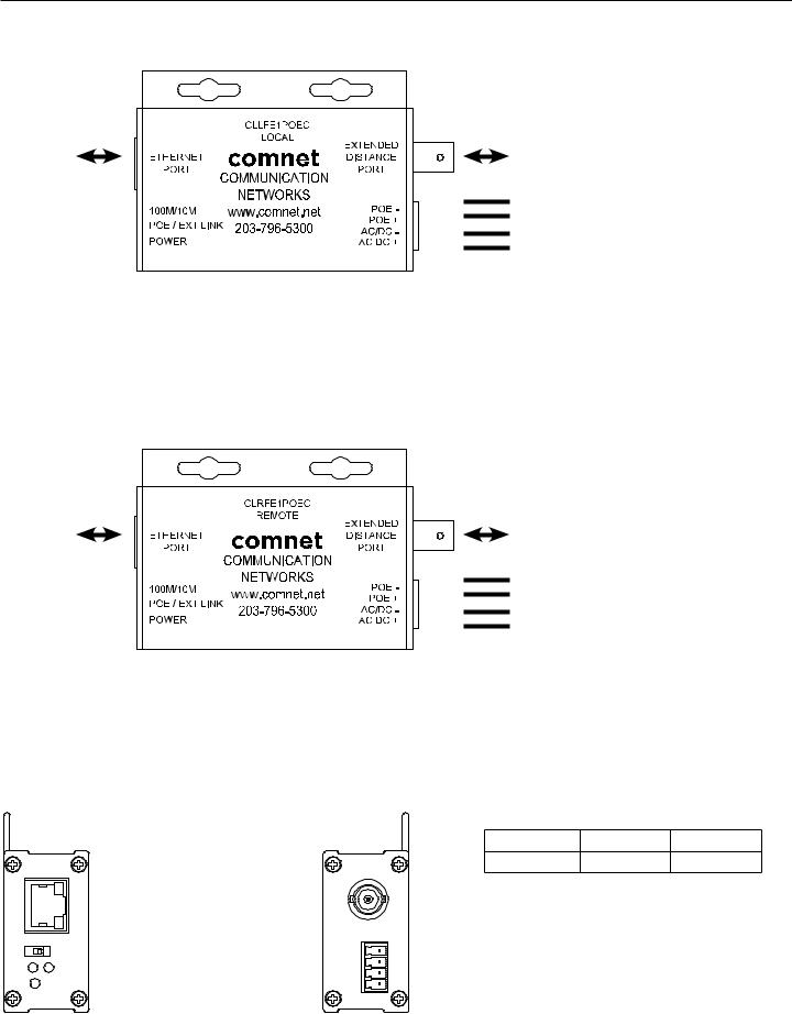
FIGURE 1 – CLLFE1POEC SINGLE CHANNEL COAX LOCAL UNIT |
|
|
Pass-Through: PoE power, or optional: |
|
9 to 36 VDC or 24 VAC, 1.5 W |
|
Power Injection: 48 to 56 VDC, 30W |
ETHERNET |
EXT DISTANCE |
|
POE– |
|
POE+ |
|
Black w/ White Stripe (AC or DC–) |
|
Black (AC or DC+) |
FIGURE 2 – CLRFE1POEC SINGLE CHANNEL COAX REMOTE UNIT
Pass-Through: PoE power, or optional:
9 to 36 VDC or 24 VAC, 1.5 W Power Injection: 48 to 56 VDC, 30W
ETHERNET |
EXT DISTANCE |
POE–
POE+
Black w/ White Stripe (AC or DC–)
Black (AC or DC+)
FIGURE 3 – CL(L,R)FE1POEC SINGLE CHANNEL COAX UNITS
DOWN |
UP |
Switch |
UP |
DOWN |
10/100 |
10 Mbps |
100 Mbps |
See Installation Instructions for more information
 10/100 data rate DIP switch
TECH SUPPORT: 1.888.678.9427
INS_CL(L,R)FE(X)POE(C,U)_REV– 10/27/11 PAGE 2
INSTALLATION AND OPERATION MANUAL |
CL(L,R)FE(X)POE(C,U) Series |
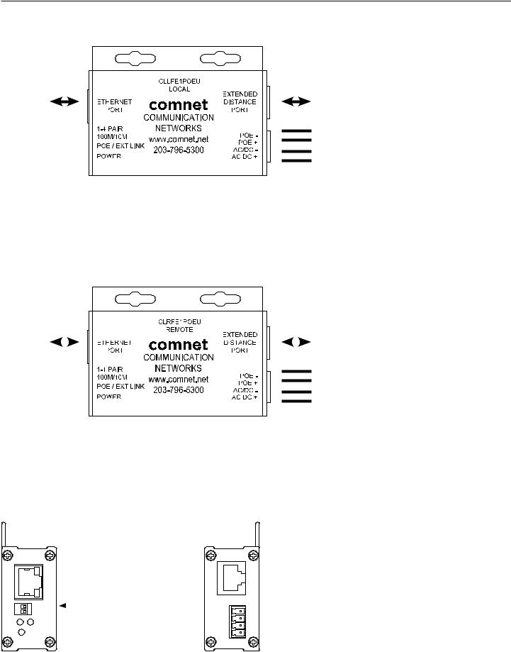
FIGURE 4 – CLLFE1POEU SINGLE CHANNEL UTP LOCAL UNIT |
|
|
Pass-Through: PoE power, or optional: |
|
9 to 36 VDC or 24 VAC, 1.5 W |
|
Power Injection: 48 to 56 VDC, 30W |
ETHERNET |
EXT DISTANCE |
|
POE– |
|
POE+ |
|
Black w/ White Stripe (AC or DC–) |
|
Black (AC or DC+) |
FIGURE 5 – CLRFE1POEU SINGLE CHANNEL UTP REMOTE UNIT
Pass-Through: PoE power, or optional:
9 to 36 VDC or 24 VAC, 1.5 W Power Injection: 48 to 56 VDC, 30W
ETHERNET |
|
|
|
|
|
EXT DISTANCE |
|
|
|
|
POE–
POE+
Black w/ White Stripe (AC or DC–)
Black (AC or DC+)
FIGURE 6 – CL(L,R)FE1POEU SINGLE CHANNEL UTP UNITS
DOWN |
UP |
 Wire pair DIP switch
  10/100 data rate DIP switch
Switch |
UP |
DOWN |
10/100 |
10 Mbps |
100 Mbps |
|
|
|
Wire Pair |
4 Pair |
1 Pair |
See Installation Instructions for more information
TECH SUPPORT: 1.888.678.9427
INS_CL(L,R)FE(X)POE(C,U)_REV– 10/27/11 PAGE 3

INSTALLATION AND OPERATION MANUAL |
CL(L,R)FE(X)POE(C,U) Series |
|
|
FIGURE 7 – CL(L,R)FE4POEC FOUR CHANNEL SURFACE OR RACK MOUNT COAX UNIT
CH1 |
CH1 EXT |
ETHERNET |
DISTANCE |
CH2 |
CH2 EXT |
ETHERNET |
DISTANCE |
CH3 |
CH3 EXT |
ETHERNET |
DISTANCE |
CH4 |
CH4 EXT |
ETHERNET |
DISTANCE |
|
POE– |
|
POE+ |
|
Black w/ White Stripe (DC–) |
|
Black (DC+) |
Pass-Through Mode |
12 to 15 VDC, 6 W |
Power Injection Mode |
48 to 56 VDC, 120W |
FIGURE 8 – CL(L,R)FE4POEC FOUR CHANNEL SURFACE OR RACK MOUNT COAX UNIT
CLLFE4POEC Local Unit Front Panel |
CLRFE4POEC Remote Unit Front Panel |
CL(L,R)FE4POEC Rear Panel |
10/100 data rate |
10/100 data rate |
DIP switch |
DIP switch |
See Installation |
See Installation |
Instructions, Step 1 |
Instructions, Step 1 |
TECH SUPPORT: 1.888.678.9427
INS_CL(L,R)FE(X)POE(C,U)_REV– 10/27/11 PAGE 4
INSTALLATION AND OPERATION MANUAL |
CL(L,R)FE(X)POE(C,U) Series |
|
|
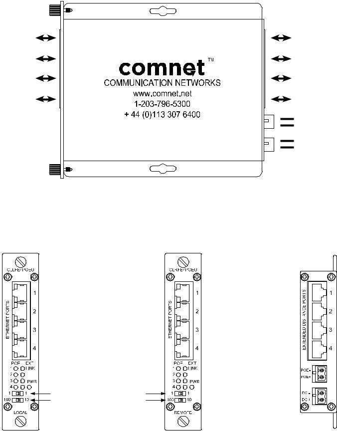
FIGURE 9 – CL(L,R)FE4POEU FOUR CHANNEL SURFACE OR RACK MOUNT UTP UNIT
CH1 |
CH1 EXT |
ETHERNET |
DISTANCE |
CH2 |
CH2 EXT |
ETHERNET |
DISTANCE |
CH3 |
CH3 EXT |
ETHERNET |
DISTANCE |
CH4 |
CH4 EXT |
ETHERNET |
DISTANCE |
|
POE– |
|
POE+ |
|
Black w/ White Stripe (DC–) |
|
Black (DC+) |
Pass-Through Mode |
12 to 15 VDC, 6 W |
Power Injection Mode |
48 to 56 VDC, 120W |
FIGURE 10 – CL(L,R)FE4POEU FOUR CHANNEL SURFACE OR RACK MOUNT UTP UNIT
CLLFE4POEU Local Unit |
CLRFE4POEU Remote Unit |
CL(L,R)FE4POEU Rear |
Wire pair DIP switch
See Installation Instructions, Step 2
10/100 data rate DIP switch
See Installation Instructions, Step 1
TECH SUPPORT: 1.888.678.9427
INS_CL(L,R)FE(X)POE(C,U)_REV– 10/27/11 PAGE 5
 Loading...