

Page 1
Page 2

Manufacturer’s Name : : Japan CBM Corporation
Manufacturer’s Address : CBM Bldg., 5-68-10, Nakano, Nakano-ku,
Declare the Product
Product Name Dot Matrix Printer
Model Number(s) CBM-820 Series
Conform to the following Standards
LVD:EN60950:A4:1997
EMC : EN55022 : 1998 Class B
Declaration of Conformity
T okyo, 164-0001, Japan
(CBM-820R, CBM-820P)
(S.No. 0090001 ~ )
: EN61000-3-2 : 1995+A1:1998+A2:1998
: EN61000-3-3 : 1995
: EN55024 : 1998
: EN61000-4-2 : 1995 ±4KV CD, ±8KV AD
: EN61000-4-3 : 1996
: EN61000-4-4 : 1995 ±1.0KV(AC Mains), ±0.5KV(Signal Lines)
: EN61000-4-5 : 1995 ±1KV (Normal mode), ±2KV (Common mode)
: EN61000-4-6 : 1996 3V, 0.15MHz-80MHz AM 1KHz 80%
: EN61000-4-8 : 1993 50Hz, 3A/m
: EN61000-4-11 : 1994 0%, 5000ms/ 70%, 500ms/ 0%, 10ms
4.5V/m, 80MHz-1000MHz AM 1KHz 80%
Supplementary Information
“The product complies with the requirements of the Low Voltage Directive 73/23/EEC, 93/68/EEC and
the EMC Directive 89/336EEC, 92/31/EEC, 93/68EEC”
Place T okyo, Japan Signature
Date September, 2000
Full Name : Mikio Moriya
Position : General Manager
R & D Department
Europe Contact :
Norco Declaration AB
Box 7146 S-250 07 Helsingborg Sweden
This declaration is applied only for 230V model.
CITIZEN
Page 3

IMPORTANT SAFETY INSTRUCTIONS
• Read all of these instructions and save them for future reference.
• Follow all warnings and instructions marked on the product.
• Unplug this product from the wall outlet before cleaning. Do not use liquid or aerosol cleaners.
Use a damp cloth for cleaning.
• Do not use this product near water.
• Do not place this product on an unstable cart, stand or table. The product may fall, causing serious
damage to the product.
• Slots and openings on the back or bottom of the case are provided for ventilation. To ensure reliable
operation of the product and to protect it from overheating, do not block or cover these openings.
The openings should never be blocked by placing the product on a bed, sofa, rug of other similar
surface. This product should never be placed near or over a radiator or heater. This product should
not be placed in an built-in installation unless proper ventilation is provided.
• This product should be operated from the type of power source indicated on the marking label. If
you re not sure of the type of power available, consult your dealer or local power company.
• Do not allow anything to rest on the power cord. Do not place this product where the cord will be
walked on.
• If an extension cord is used with this product, make sure that the total of the ampere ratings of the
products plugged into the extension cord does not exceed the extension cord ampere rating. Also,
make sure that the total of all products plugged into the wall outlet does not exceed 15 amperes.
• Never push objects of any kind into this product through cabinet slots as they may touch dangerous
voltage points or short out parts that could result in a risk of fire or electric shock. Never spill liquid
of any kind on the product.
• Except as explained elsewhere in this manual, do not attempt to service this product by yourself.
Opening and removing the covers that are marked “Do Not Remove” may expose you to dangerous
voltage points or other risks. Refer all servicing on those compartments to service personnel.
• Unplug this product from the wall outlet and refer servicing to qualified service personnel under
the following conditions:
A. When the power cord or plug is damaged or frayed.
B. If liquid has been spilled into the product.
C. If the product has been exposed to rain or water.
D. If the product does not operate normally when the operating instructions are followed. Adjust
only those controls that are covered be the operating instructions since improper adjustment of
other controls may result in damage and will often require extensive work by a qualified
technician to restore the product to normal operation.
E. If the product has been dropped or the cabinet has been damaged.
F. If the product exhibits a distinct change in performance, indicating a need for service.
• Please keep the poly bag which this equipment is packed in away from children or throw it away to
prevent children from putting it on. Putting it on may cause suffocation.
Page 4

WICHTIGE SICHERHEITSANWEISUNGEN
• Lesen Sie die nachfolgenden Anweisungen sorgfältig durch und bewahren Sie sie auf.
• Befolgen Sie alle auf dem Drucker vermerkten Hinweise und Anweisungen. Vor dem Reinigen
grundsätzlich Stecker aus der Steckdose ziehen. Keine Flüssigkeiten oder Aerosolreiniger
benutzen. Nut mit einem feuchten Tuch abwischen.
• Der Drucker darf nicht in der Nähe von Wasser aufgestellt werden.
• Drucker nicht auf einem unstabilen Wagen, Stand oder Tisch aufstellen. Der Drucker könnte
herunterfallen und dabel beschädigt werden.
• Schlitze und Öffnungen im Gehäuse, in der Rückwand und im Boden dienen der Belüftung. Sie
dürfen keinesfalls zugedeckt oder blockiert werden, da sich der Drucker sonst überhitzt. Drucker
nicht auf ein Bett, Sofa, Teppich oder dergleichen stellen. Drucker nicht in der Nähe eines
Heizkörpers aufstellen. Drucker darf nicht eingebaut werden, falls nicht für ausreichende
Belüftung gesorgt ist.
• Drucker nur mit der auf dem Typschild angegebenen Spannung betreiben. Wenn Sie sich nicht
sicher sind, fragen Sie ihren Händler oder ihr zuständiges Elektrizitätswerk.
• Nichts auf das Stromanschlußkabel stellen. Kabel muß so verlegt werden, daß man nicht
darauftreten kann.
• Ein etwaiges Verlängerungskabel muß der Stromstärke aller daran angeschlossenen Geräte
entsprechen.
• Keine Gegenstände in die Gehäuseschlitze schieben.
• Drucker darf nur da gewartet werden, wo im Handbuch angegeben, Öffnen und. Abnehmen von
Abdeckungen, die mit “Do not remove” gekennzeichenet sind, könnte gefährliche spannungführende Stellen oder sonstige Gefahrenpunkte freilegen. Die Wartung solcher Stellen darf
grundsätzlich nur von besonders ausgebildetem Fachpersonal vorgenommen werden.
A. Wenn das Stromanschlußkabel oder der Stecker beschädigt oder durch-gescheuert ist.
B. Wenn Flüssigkeit auf dem Drucker verschüttet wurde.
C. Wenn der Drucker im Regen gestanden hat oder Wasser darauf verschüttet wurde.
D. Wenn der Drucker trotz genauer Befolgung der Betriebsvorschriften nicht richtig arbeitet. Nur
die in der Bedienungsanleitung angegebenen Einstellungen vornehmen. Ein Verstellen anderer
Bedienungselemente könnte den Drucker beschädigen und macht umständliche Arbeiten eines
qualifizierten Technikers erforderlich, um den Drucker Wieder auf den normalen Betrieb
einzustellen.
E. Wenn der Drucker heruntergefallen ist oder das Gehäuse beschädigt wurde.
F. Wenn der Drucker in seiner Leistung nachläßt.
• Bitte halten Sie den Kunststoffbeutel, in den die Ware verpackt ist, von Kindern entfernt, oder
werfen Sie ihn weg, damit er nicht in die Hande von Kindern gerät. Das Überstülpen des Beutels
kann zum Ersticken führen.
Lärmemission kleiner 70 dBA
Page 5

IMPORTANT:
installed and used in accordance with the instruction manual, may cause interference to radio
communications. It has been tested and found to comply with the limits for a Class A computing
device pursuant to Subpart J of Part 15 off FCC Rules, which are designed to provide reasonable
protection against such interference when operated in a commercial environment. Operation of this
equipment in a residential area is likely to cause interference, in which case the user at his own
expense will be required to take whatever measures may be necessary to correct the interference.
This equipment generates, uses, and can radiate radio frequency energy and if not
CAUTION: Use shielded cable for this equipment.
Sicherheitshinweis
Die Steckdose zum Anschluß dieses Druckers muß nahe dem Grät angebracht und leicht zugänglich
sein.
For Uses in Canada
This digital apparatus does not exceed the class A limits for radio noise emissions from digital,
apparatus, as set out in the radio interference regulations of the Canadian department of
communications.
Pour L’utilisateurs Canadiens
Cet appareil numérique ne dépasse pas les limites de carégorie a pour les émissions de bruit radio
émanant d'appareils numériques, tel que prévu dans les réglements sur l'interférence radio du
départment Canadien des communications.
Page 6

< CAUTIONS >
1. Prior to using the equipment, be sure to read this User’s Manual thoroughly. Please keep it handy for
reference whenever it may be needed.
2. The information contained herein may be changed without prior notice.
3. Reproduction of part or all of this User’s Manual without permission is strictly prohibited.
4. Never service, disassemble, or repair parts that are not mentioned in this User’s Manual.
5. Note that we will not be responsible for damages attributable to a user’s incorrect operation/ handling or
an improper operating environment.
6. Operate the equipment only as described in this User’s Manual; otherwise accidents or problems may
result.
7. Data are basically temporary; they cannot be stored or saved permanently or for a long time. Please note
that we will not be responsible for damages or losses of profit resulting from losses of the data
attributable to accidents, repairs, tests, and so on.
8. If you have any questions or notice any clerical errors or omissions regarding the information in this
manual, please contact our office.
9. Please note that, notwithstanding Item 8 above, we will not be responsible for any effects resulting from
operation of the equipment.
Note:
• CITIZEN and CITIZEN logo are registered trademarks of CITIZEN WATCH CO., LTD.
• ESC/POS and TM-295 are trademarks of SEIKO EPSON CORPORATION.
• Auto Side Loading™ is a trademark of Star Micronics Co., Ltd.
• Windows codepage is a registered trademark of Microsoft Corporation.
Page 7
●
SAFETY PRECAUTIONS ----- BE SURE TO OBSERVE
In order to prevent hazards to an operator or other persons and damage to property, be sure to observe the
following precautions.
The following describes the degrees of hazard and damages that can occur if the given instructions are
neglected or the equipment is incorrectly operated.
WARNING
CAUTION
This is an illustration mark used to alert your attention.
This is an illustration mark used to indicate such information as an instruction or the like.
Negligence of this precaution may result in death or serious injury.
Negligence of this precaution may result in injury or damage to
property.
Page 8
●
●
WARNING
Never handle the equipment in the following manners, as it may break, become out of order, or
overheat causing smoke and resulting in fire or electric shock.
If the equipment is used in an abnormal condition, such as when broken, then problems, smoke
emission, abnormal odor/noise, and fire can result. If an abnormal condition exists, be sure to
disconnect the power plug from a plug socket, and contact our dealer. Never repair the equipment
on your own - it is very dangerous.
• Do not allow the equipment to receive a strong impact or shock, such as kicking, stomping, hitting,
dropping, and the like.
• Install the equipment in a well-ventilated place. Do not use it in such a manner that its ventilation
port will be blocked.
• Do not install the equipment in a place like a laboratory where chemical reactions are expected, or
in a place where salt or gases are contained in the air.
• Do not connect/disconnect a power cord or a data cable, while holding the cable. Do not pull,
install, use, or carry the equipment in such a manner that force will be applied to the cables.
• Do not drop or insert any foreign substances, such as clips or pins, into the equipment.
• Do not spill any liquid or spray any chemical-containing liquid over the equipment. If any liquid
is spilled on it, turn off the power, disconnect the power cable and power cord from the plug socket,
and so on, and contact our dealer.
• Never disassemble or remodel the equipment. Negligence of this may cause fire or electric shock.
• Use the equipment only with the specified commercial power supply and AC adapter. Negligence
of this may result in fire, electric shock, or problems.
• If you drop or break the AC adapter, or if water or the like gets inside it, unplug it immediately from
the socket and contact your dealer.
• Do not damage, break, process, bend/pull by force, twist, or head an AC adapter cord. Also, do not
put a heavy substance on it or heat it. The AC adapter cord could be broken, resulting in fire,
electric shock, or trouble. If the AC adapter cord is damaged, contact our dealer.
• Do not connect/disconnect the AC adapter with wet hands.
• Do not overload a single electrical outlet, using a table tap or a current tap socket.
An equipment packing bag must be discarded or kept away from children. A child can suffocate
if the bag is placed over the head.
Page 9

PRECAUTIONS FOR INSTALLATION
• Do not use or store the equipment in a place exposed to fire, moisture, or direct sunshine, or in a
place near a heater or thermal device where the prescribed operating temperature and humidity are
not met, or in a place exposed to much oil, iron powder, or dust. The equipment may become out
of order, emit smoke, or catch fire.
• Do not install or use the equipment in a place like a laboratory where chemical reactions are
expected, or in a place where salt or gases are contained in the air. There is a danger of fire or
electric shock.
• Install the printer on a flat, stable desk or table that is free from vibration, in a well-ventilated place.
• Do not install the printer at a location where its operation could be hindered.
• Do not place anything on the printer or leave small objects, like a clip or pin, around it. A foreign
object could cause trouble if it gets inside.
• Do not use any sharp-pointed object, such as a pen, for example, to touch the operation panel of the
printer. It could cause trouble.
• Do not use the equipment near a radio or TV receiver. Do not share the power from a plug socket
a radio or TV receiver is connected to. It may cause a reception problem.
• Use the equipment only at the specified power supply, voltage and frequency. Otherwise, it may
emit smoke and catch fire or cause other problems.
• Connect only the specified power source. Use of an unspecified power source could cause trouble
or smoke/fire.
• Confirm that a plug socket used for connection has sufficient capacity.
• Avoid connecting a power cable to a plug socket shared by other devices or extending the wiring
too far. It may result in the cable catching fire or a power outage. Also, do not step on or apply an
excessive force (Pull, load) to the cable, and do not use the printer with such a force applied to it.
• Never connect a grounding cable (Frame ground) to a gas pipe. There is a danger of explosion.
When connecting or disconnecting the grounding cable, be sure to disconnect the power cable and
the power plug from the plug socket.
• When connecting/disconnecting the cables, be sure to turn off the power first, including the
connected side, and then connect/disconnect them, holding a plug and a connector. Pulling the
cable itself could cause it to snap or become damaged.
• Connect a power cable or a connector cable securely. If a reverse-polarity connection is made,
internal elements may be broken or a mating device may be adversely affected.
• Use a shielding wire or twisted pair wire for a signal line, in order to minimize noise effect. Do not
route the cable too long or connect it to a noisy device. Connection to a noisy device could cause
erroneous printing due to corrupt data, and so on.
• Use the equipment in an environment where there is a plug socket near the main body and you can
easily disconnect the power plug from it, to shut off the power.
• When the equipment will not be used for a long period of time, unplug it and remove the paper roll
from it.
• When transporting the equipment, remove the paper roll from the paper holder.
Page 10

PRECAUTIONS FOR HANDLING
Do not handle the equipment in the following manners, because problems may result.
• Do not use any other power source besides the accessory AC adapter. Also, do not use the AC
adapter for other purposes.
• Do not print without paper.
• Do not drop or put any foreign object, such as a clip, pin, or the like, inside the printer.
• Do not spill any liquid or spray any chemical-containing liquid over the equipment.
• Never use a pointed object, such as a pen, to operate the operation panel.
• Do not use Scotch tape to fasten paper together for continuous use. It could damage the printing
head.
• Never pull the set paper forcibly. When opening/closing the printer cover, take care that the paper
will not be caught. It could cause the paper to jam.
• Be sure to use the specified paper. Use of other paper could deteriorate the print quality or cause a
problem with the printing head.
To Prevent Injury and Spreading of Damage
• Never touch the printing head, motor, or paper cutting blade. Your finger may be cut.
• During power-on or immediately after printing, do not touch electrical parts or moving parts, such
as the mechanism, motor, internal gear, etc. They may be very hot and can burn your hand/finger.
• Be careful to avoid bodily injure or damaging other objects with an edge of sheet metal.
• Should any error occur while operating the equipment, stop it immediately and disconnect the
power plug from the plug socket.
• Only a qualified serviceman is allowed to disassemble or repair the printer.
• Should a problem occur, leave solving it to our serviceman. Do not disassemble the equipment on
your own.
• When opening/closing the printer cover, and so on, be careful not to catch your hand or finger on
the equipment.
• After using the equipment, turn off the power switch and unplug the AC adapter from a plug socket.
Page 11
DAILY MAINTENANCE
• At the time of maintenance, be sure to turn off the power switch of the printer and unplug it from
the socket.
• Use a dry soft cloth to wipe off stains and dust from the surfaces of the main body case. For severe
soiling, dip the cloth in water and wring it, for wiping off the soil. Never use organic solvents, such
as alcohol, thinner, trichlene, benzene, ketone, or chemical dusters.
• If the equipment is contaminated with paper powder, use a soft brush to clean it. Be careful not to
damage the printing head.
CAUTION :
The printing head and motor are very hot. Be careful not to touch them
immediately after printing. Do not touch the heating surface of the head
with a bare hand or metal.
Page 12

CONTENTS
1. Printer Setup.................................................................................................................... 1
1.1 Choosing a place for the printer............................................................................. 1
1.2 Unpacking the printer ............................................................................................2
1.3 Removing the protective materials ........................................................................ 3
2. Specifications ................................................................................................................... 4
2.1 General Specifications ...........................................................................................4
2.2 Printing Specifications........................................................................................... 5
2.3 Paper Specifications and Print Area ......................................................................5
2.4 Power Supply Specifications ................................................................................. 7
3. Outer Appearance and Component Parts ....................................................................8
3.1 General guide......................................................................................................... 8
4. Operation ......................................................................................................................... 9
4.1 Removing the printer cover ...................................................................................9
4.2 Installing the ribbon cassette..................................................................................9
4.3 Removing the ribbon cassette .............................................................................. 11
4.4 Connecting to a power outlet and turning power on and off ............................... 11
4.5 Connecting to your host computer.......................................................................13
4.6 Connecting to a peripheral unit............................................................................ 15
4.7 Inserting the paper into the printer....................................................................... 16
4.8 AutoSide Loading™ ............................................................................................17
4.9 Control Panel Operations.....................................................................................19
4.9.1 Indicator lights..............................................................................................19
4.9.2 Buttons .........................................................................................................19
4.9.3 Producing a test print....................................................................................20
4.9.4 Adjusting the dot alignment .........................................................................20
4.9.5 Hexadecimal dump....................................................................................... 22
4.9.6 Errors............................................................................................................ 23
4.10 Paper Sensors .......................................................................................................24
5. Making DIP Switch Settings.........................................................................................25
5.1 Accessing the DIP switches................................................................................. 25
5.2 Available DIP switch settings..............................................................................27
5.3 Memory Switch Settings...................................................................................... 28
6. Interface .........................................................................................................................29
6.1 Pins and Signal Names ........................................................................................29
6.2 Interface Connections .......................................................................................... 30
7. Peripheral Unit Driver Circuit.....................................................................................31
7.1 Modular plug........................................................................................................31
7.2 Drive circuit .........................................................................................................32
8. Maintenance and Service..............................................................................................33
9. Print Control Functions................................................................................................ 34
9.1 List of ESC/POS Commands............................................................................... 34
9.2 Command Details ................................................................................................36
9.2.1 Description of Each Items ............................................................................36
9.2.2 Command Details......................................................................................... 37
Page 13

10. Character Codes Table .................................................................................................76
10.1 Codepage PC437 (USA, European Standard)................................................... 76
10.2 Codepage Katakana (Japanese) .........................................................................77
10.3 Codepage PC850 (Multilingual) .......................................................................78
10.4 Codepage PC860 (Portuguese).......................................................................... 79
10.5 Codepage PC863 (Canadian-French)................................................................ 80
10.6 Codepage PC865 (Nordic) ................................................................................81
10.7 Codepage PC852 (Eastern Europe)................................................................... 82
10.8 Codepage PC866 (Russian)...............................................................................83
10.9 Codepage PC857 (Turkish) ............................................................................... 84
10.10 Windows Codepage........................................................................................... 85
10.11 Codepage PC858 (Multilingual+Euro) .............................................................86
Appendix 1: Outline Drawing of Printer (CBM-820) ....................................................87
Appendix 2: Outline Drawing of AC Adapter (31AD) ..................................................88
<<< German >>>
1. Drucker-Einrichtung ....................................................................................................96
1.1 Wahl eines Aufstellungsorts für den Drucker......................................................96
1.2 Auspacken des Druckers...................................................................................... 97
1.3 Entfernen der Schutzmaterialien.......................................................................... 98
2. Technische Daten...........................................................................................................99
2.1 Allgemeine Daten ................................................................................................ 99
2.2 Druckspezifikationen .........................................................................................100
2.3 Papier-Spezifikationen und Druckbereich ......................................................... 100
2.4 Technische Daten zur Netzversorgung .............................................................. 102
3. Außenansicht und Bauteile......................................................................................... 103
3.1 Allgemeine Anleitung........................................................................................103
4. Betrieb ..........................................................................................................................104
4.1 Abnehmen der Druckerabdeckung ....................................................................104
4.2 Einsetzen der Farbbandkassette ......................................................................... 104
4.3 Entnehmen der Farbbandkassette ......................................................................106
4.4 Anschluß an eine Netzsteckdose und Ein-/Ausschalten der Netzversorgung ... 106
4.5 Anschließen an den Hostcomputer .................................................................... 108
4.6 Anschluß an ein Peripheriegerät ........................................................................ 110
4.7 Papier in den Drucker einlegen.......................................................................... 111
4.8 Automatischer Papiereinzug (AutoSide Loading™)......................................... 112
4.9 Bedienfeld.......................................................................................................... 114
4.9.1 Anzeigeleuchten .........................................................................................114
4.9.2 Tasten ......................................................................................................... 115
4.9.3 Erstellen eines Testdrucks.......................................................................... 115
4.9.4 Einstellen der Punktausrichtung.................................................................115
4.9.5 Sedezimaler Datenausdruck .......................................................................117
4.9.6 Fehler.......................................................................................................... 118
4.10 Papiersensoren ...................................................................................................119
Page 14

5. DIP-Schaltereinstellung.............................................................................................. 120
5.1 Zugang zu den DIP-Schaltern............................................................................120
5.2 Verwendbare DIP-Schaltereinstellungen........................................................... 122
5.3 Einstellen der Speicherschalter.......................................................................... 123
6. Schnittstelle.................................................................................................................. 124
6.1 Stifte und Signalnamen...................................................................................... 124
6.2 Schnittstellenanschlüsse.....................................................................................125
7. Treiberschaltung für periphere Einheiten................................................................126
7.1 Modularstecker ..................................................................................................126
7.2 Treiberschaltung ................................................................................................127
8. Wartung und Dienst....................................................................................................128
Page 15

1. Printer Setup
This chapter contains important information on setting up your printer. Be sure
to read this chapter carefully before using the printer for the first time. In this
chapter you will learn about:
Choosing a place for the printer
❏
Unpacking and setting up the printer
❏
Installing the ribbon cassette
❏
Connecting to a host computer
❏
Inserting paper
❏
1.1 Choosing a place for the printer
Before actually unpacking the printer, you should take a few minutes to think
about where you plan to use it. Remember the following points when doing this.
✓
Choose a firm, level surface where the printer will not be exposed to
vibration.
The power outlet you plan to connect to for power should be nearby and
✓
unobstructed.
✓
Make sure that the printer is close enough to your host computer for you to
connect the two.
✓
Make sure that the printer is not exposed to direct sunlight.
✓
Make sure that the printer is well away from heaters and other sources of
extreme heat.
Make sure that the surrounding area is clean, dry, and free of dust.
✓
Make sure that the printer is connected to a reliable power outlet. It should
✓
not be on the same electric circuit as copiers, refrigerators, or other
appliances that cause power spikes.
✓
Use a power outlet that matches the power rating noted on the label affixed
to the bottom of your printer.
Make sure that the room where you are using the printer is not too humid.
✓
– 1 –
Page 16
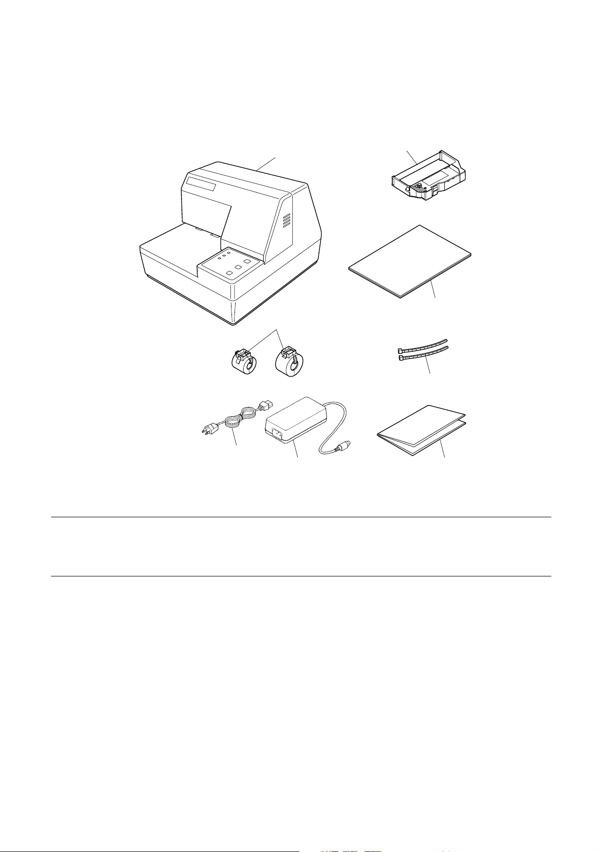
1.2 Unpacking the printer
Check to make sure that the carton contains each of the items shown in the
following illustration.
Printer
Ferrite core
Ribbon cassette
User’s Manual
Fastener
Note:
AC Cable
AC Adapter
Notes of the AC adapter
The AC adapter is accompanied by Notes. Be sure to read this document prior
to using the AC adapter, and keep it together with this manual.
If anything is missing, contact the dealer where you bought the printer and ask
them to supply the missing part. Note that it is a good idea to keep the original
box and all the packing materials just in case you need to pack the printer up
again and send it somewhere at a later date.
Always keep the Instruction Manual and Notes near the printer, for ready
reference whenever necessary.
– 2 –
Page 17
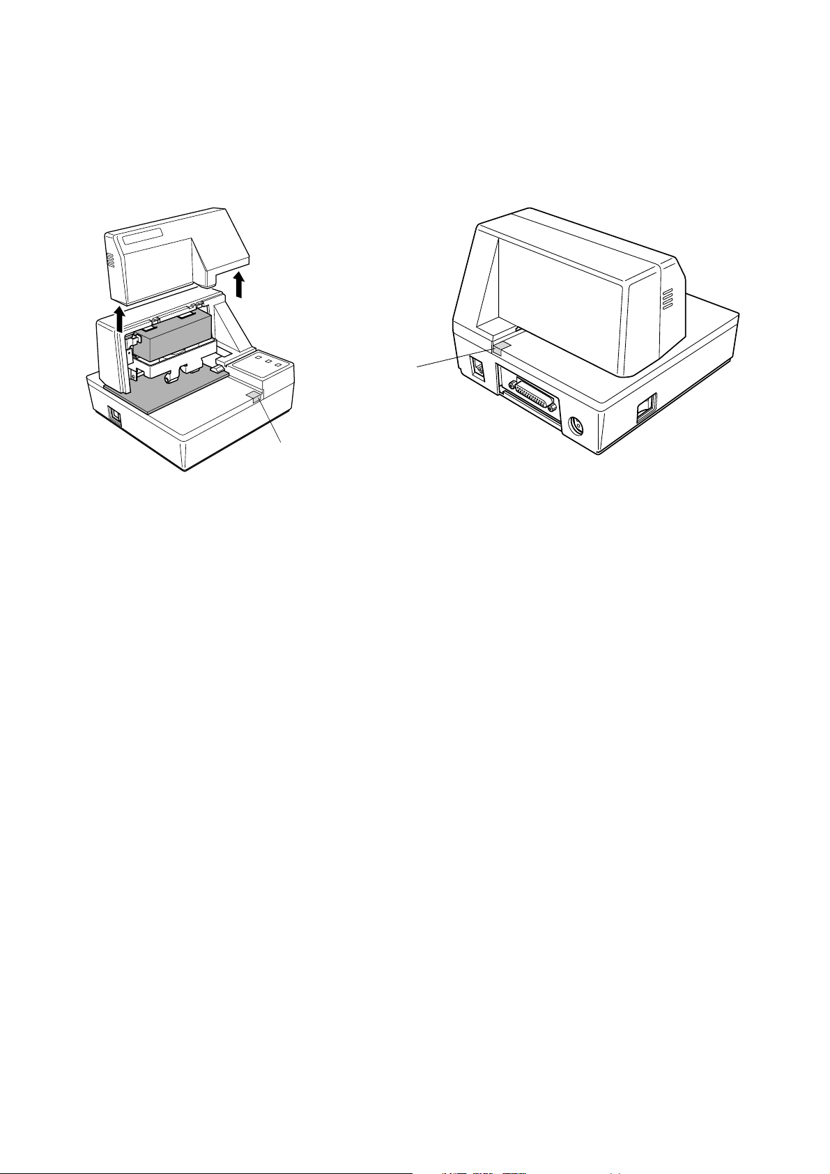
1.3 Removing the protective materials
Four protective materials are inserted into the printer to protect components
during shipping. Before using the printer, be sure to remove all protective
materials as shown in the illustration.
tape
tape
– 3 –
Page 18

2. Specifications
2.1 General Specifications
Printing System Serial impact dot-matrix
Number of Head Pins 9 wires
Printing Speed 3.1 lines/sec maximum
Number of Print Columns 35
Total dots 210
Printing width 63 mm
Dot spacing Horizontal: 0.30mm
Vertical: 0.35mm
Paper Width 80mm to 182mm
Sensors Paper out top-of-form, bottom-of-form sensors
Command Modes ESC/POS mode (TM-295 emulation)
Interface Serial (RS-232C standard)
Data Buffer 2 K bytes / 35 bytes
(Can be selected by DIP switch)
Reliability Mechanism (MCBF): 2.5 million lines
Printer head life: 70 million characters
Operating Environment
Temperature 41 ° F to 104 ° F (5 ° C to 40 ° C)
Humidity 10% to 80% RH at 40 ° C (non-condensing)
Storage Environment
Temperature -4 ° F to 140 ° F (-20 ° C to 60 ° C)
Humidity 5% to 90% RH at 40 ° C (non-condensing)
Reliability
Printable lines MCBF 2,500,000 lines
Head life 70,000,000 characters
Ink Ribbon
Type Cartridge cassette
Color Purple
Ribbon Material Nylon # 40 denier
Life 2.2 million characters
Important!
Use only the specified type of ribbon. Use of another type of ribbon can cause
malfunction of and damage to the printer.
Applicable Standards
115 V model: UL, C-UL, FCC Class-A
230 V model: TÜV, CE Marking
Those standards are applicable when our exclusive AC adapter (31AD series) is used.
✳
– 4 –
Page 19

2.2 Printing Specifications
7 ×
7 ×
Character Set
Character Matrix
Character Dimensions
Codepage PC437 (USA, European Standard)
Codepage Katakana (Japanese)
Codepage PC850 (Multilingual)
Codepage PC860 (Portuguese)
Codepage PC863 (Canadian-French)
Codepage PC865 (Nordic)
Codepage PC852 (Eastern Europe)
Codepage PC866 (Russian)
Codepage PC857 (Turkish)
Windows Codepage
Codepage PC858 (Multilingual+Euro)
9 (half), 42 columns
5 × 9, 35 columns
9 font (half): 1.2 (W) × 2.42 (H) mm
5 × 9 font (2 pulses per dot): 1.5 (W) × 2.42 (H) mm
5 × 9 font (3 pulses per dot): 2.1 (W) × 2.42 (H) mm
2.3 Paper Specifications and Print Area
Paper Width
Paper Length
Copies
Paper Thickness
Copy Offset
Binding
Print Area
80 to 182mm / 3.15 ″ to 7.17 ″
80 to 257mm / 3.15 ″ to 10.8 ″
Original + 2
1-ply: 0.09 to 0.2mm / 0.0035 ″ to 0.0079 ″
Duplicates 0.12 mm (minimum for 2-ply forms) to 0.25 mm/0.0047 ″ to 0.0098 ″
<Maximum 0.2 mm when printing graphics>
1.5mm maximum/15 lines (between top sheet and bottom sheet)
Top or left
Distance from first printed line (Head #1) to top of form (form stopper): 28.6 mm
Distance from first printed line (Head #1) to TOF sensor: 26.0 mm
(However, with the automatic start position operation, this distance is set to 26.5 mm.
The automatic start position operation can be enabled or disabled with the memory
switches.
When the top-of-form sensor is disabled, a command can be used to perform a reverse
paper feed enabling printing to begin at approximately 20 mm from the top of the paper.)
Distance from last printed line (Head #9) to bottom of form (BOF sensor): 38.1 mm
(Printing may continue to 27.3 mm from the bottom of the paper.)
When the BOF sensor is disabled, printing can continue to 14.0 mm from the bottom of
the paper.
Right margin: 5.1 mm
Print area width: 62.7 mm
– 5 –
Page 20
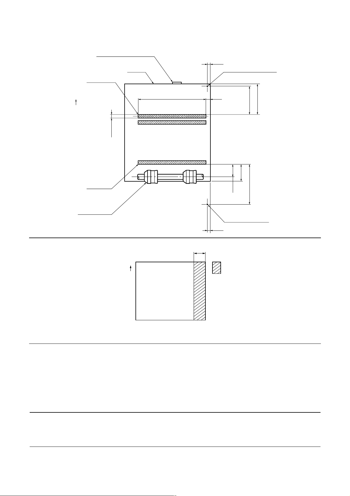
Form stopper (fixed)
Paper
Head #1
3.2
TOF sensor (fixed)
Print Position
Paper feed direction
2.82
Head #9
Paper feed
roller
62.7
First printed line
Last printed line
8 mm
5.1
14
11.9
BOF sensor (fixed)
3.2
26.0
38.1
28.6
Paper feed
direction
Do not use paper with perforations within the shaded area. Perforations may cause the
paper sensor to erroneously report an out of paper condition.
Paper Feed
Drive Stepping motor
Pitch Adjustable in n /60 ″ units (approximate)
Speed (while printing) 3.5 ″ per second
Speed (while ejecting) 4.5 ″ per second
Important!
Slip paper must be flat, smooth, and free of curls, bends, wrinkles and folds, all
of which can cause jamming and soiling by ink.
No holes in this area
– 6 –
Page 21

2.4 Power Supply Specifications
Power Supply
AC Adaptor 31AD, switching type
Input AC100 to 240V 50/60Hz
Output DC 24V ± 5%, 1.9A
Plug TCP8927-83-1100 (Hoshiden brand or equivalent.)
Consumption Current
Conditions: DC 24V, excluding external equipment driving
Operating
(approximate averages)
Stand-by
(approximate averages)
Continuous ASCII printing + paper feed: 0.6A
Solid block printing + paper feed: 1.0A
Solid block printing: 1.9A
Peak (solid printing): 3.1A
Paper release deactivated: 0.24 A
Paper release activated: 0.07A
Important!
• When using a printer power supply other than the specified AC adaptor
(31AD), be sure that the following cautions are observed.
• Use a power supply of DC 24 V ±5% and more than 1.9 A.
• Be careful about installing the printer in an area where there is noise. Take the
appropriate measures to protect against electrostatic AC line noise, etc.
– 7 –
Page 22
3. Outer Appearance and Component Parts
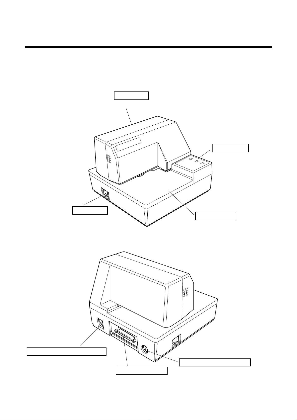
3.1 General guide
The following illustrations describe the major components, buttons, and
connectors of your printer.
Printer cover
Protects internal components.
Power switch
Turns printer
power on and off.
Control panel
Three indicators show
the printer status, and
two switches provide
control over printer
functions.
Document table
Supports the paper fed
into the printer.
Peripheral unit connector cover
Covers a modular jack for
connection of a cash drawer or
other peripheral.
Do not connect a telephone line
to this connector.
Interface connector
For connection
to a host computer.
– 8 –
AC adapter cable connector
For connection of the AC adapter.
Never unplug the AC adapter
while the printer is on.
Page 23
4. Operation
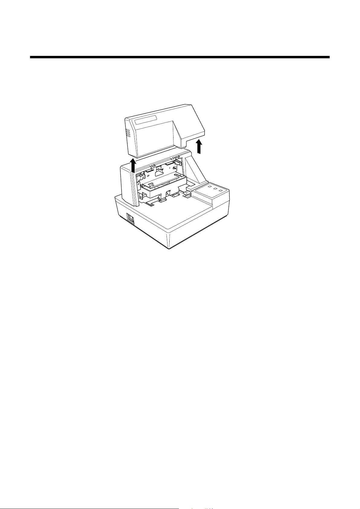
4.1 Removing the printer cover
Push straight up on the ridged locations on the sides of the printer cover to
❏
remove it from the printer.
To replace the cover, slide it back down into position. Gently press down on
❏
the cover until you hear it click securely into place.
4.2 Installing the ribbon cassette
❏
Make sure that the printer's paper release is activated (the paper is not held
in place by the paper feed roller). If it cannot be determined whether or not
the paper release is activated, turn on the printer and check if the
RELEASE indicator on the control panel is lit. If the indicator is not lit,
press the RELEASE button until the indicator lights up.
❏ Make sure that the printer is turned off and unplugged from its power
outlet.
❏ Remove the printer cover.
– 9 –
Page 24
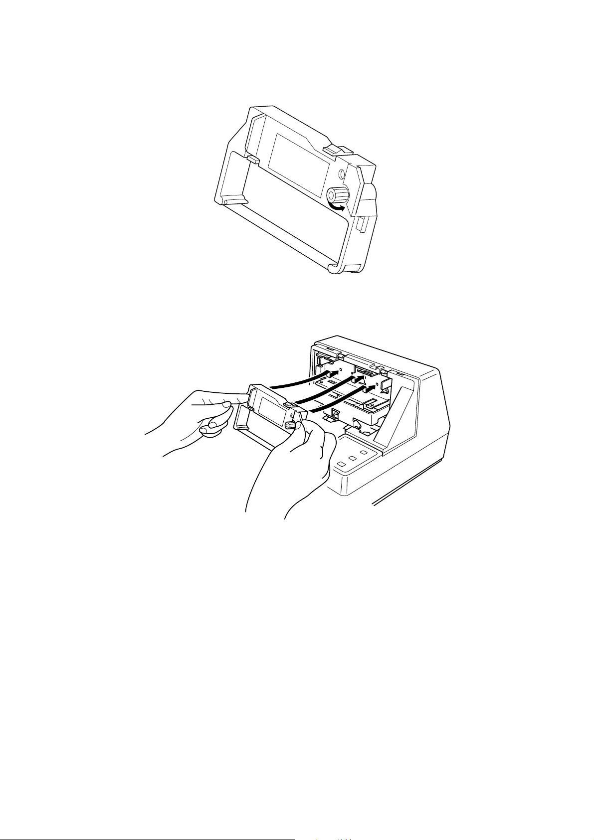
❏ Remove the ribbon cassette from its packaging, and turn its knob in the
direction indicated by the arrow to take up any slack in the ribbon.
❏ Holding the ribbon cassette so that the ribbon is facing down, install the
cassette into the slip printer as shown in the illustration.
❏ Press gently but firmly on the cassette until it snaps securely into place.
❏ Rotate the knob on the cassette again to take up any slack.
❏ Replace the printer cover.
– 10 –
Page 25
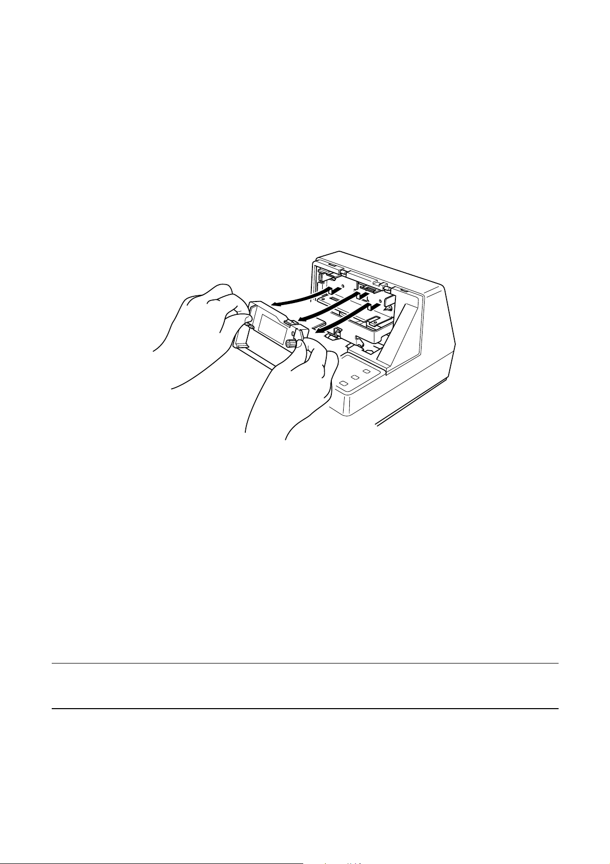
4.3 Removing the ribbon cassette
Use the following procedure to remove the ribbon cassette from the slip printer
when you want to replace it with a new one.
❏ Make sure that the printer is turned off and unplugged from its power
outlet.
❏ Remove the printer cover.
❏ Grasping the ribbon cassette as shown, gently pull it away from the printing
mechanism.
❏ Use the procedure under “Installing the ribbon cassette” on page 9 to install
a new cassette.
4.4 Connecting to a power outlet and turning power on and off
❏
Make sure that the printer is turned off.
❏ Plug the AC adapter that comes with the printer into the printer’s AC
adapter cable connector.
❏ Connect a three-prong grounded power cord to the power cord connector of
the AC adapter.
Note:
The printer does not come with a power cord, so you must provide one yourself.
– 11 –
Page 26
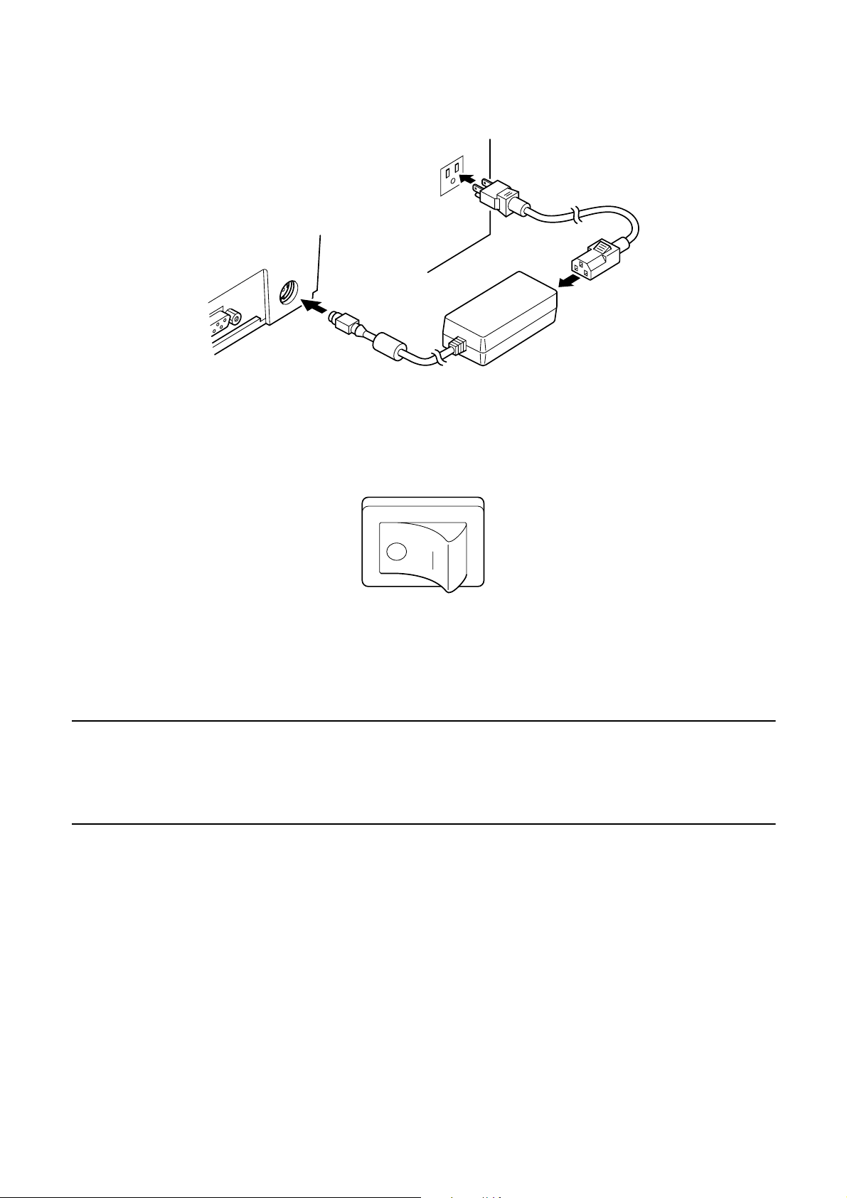
❏ Plug the other end of the power cord to a standard household wall outlet.
❏ Use the power switch on the left side of the printer to turn power on and off.
Important!
We recommend that you unplug the printer from the power outlet whenever you
do not plan to use it for long periods. Because of this, you should locate the
printer so that the power outlet it is plugged into is nearby and easy to access.
At this point you may want to perform a test of the printer to make sure it is
working properly. See page 20 for details on how to test the printer.
– 12 –
Page 27
4.5 Connecting to your host computer
The computer sends data to the printer through a cable to the printer’s standard
serial interface (Connector Type: D-sub 25-pin). This printer does not come
with a cable, so it is up to you to obtain one that suits your needs.
Important!
• The following instructions apply to the interface cable that is used with an
IBM-compatible personal computer. Note that they do not apply to all types of
computers and cables. If you are unsure about what type of cable you should
use to connect with your computer, consult your dealer.
• Make sure that the printer is turned off and unplugged from the AC outlet and
that the computer is turned off before connecting them.
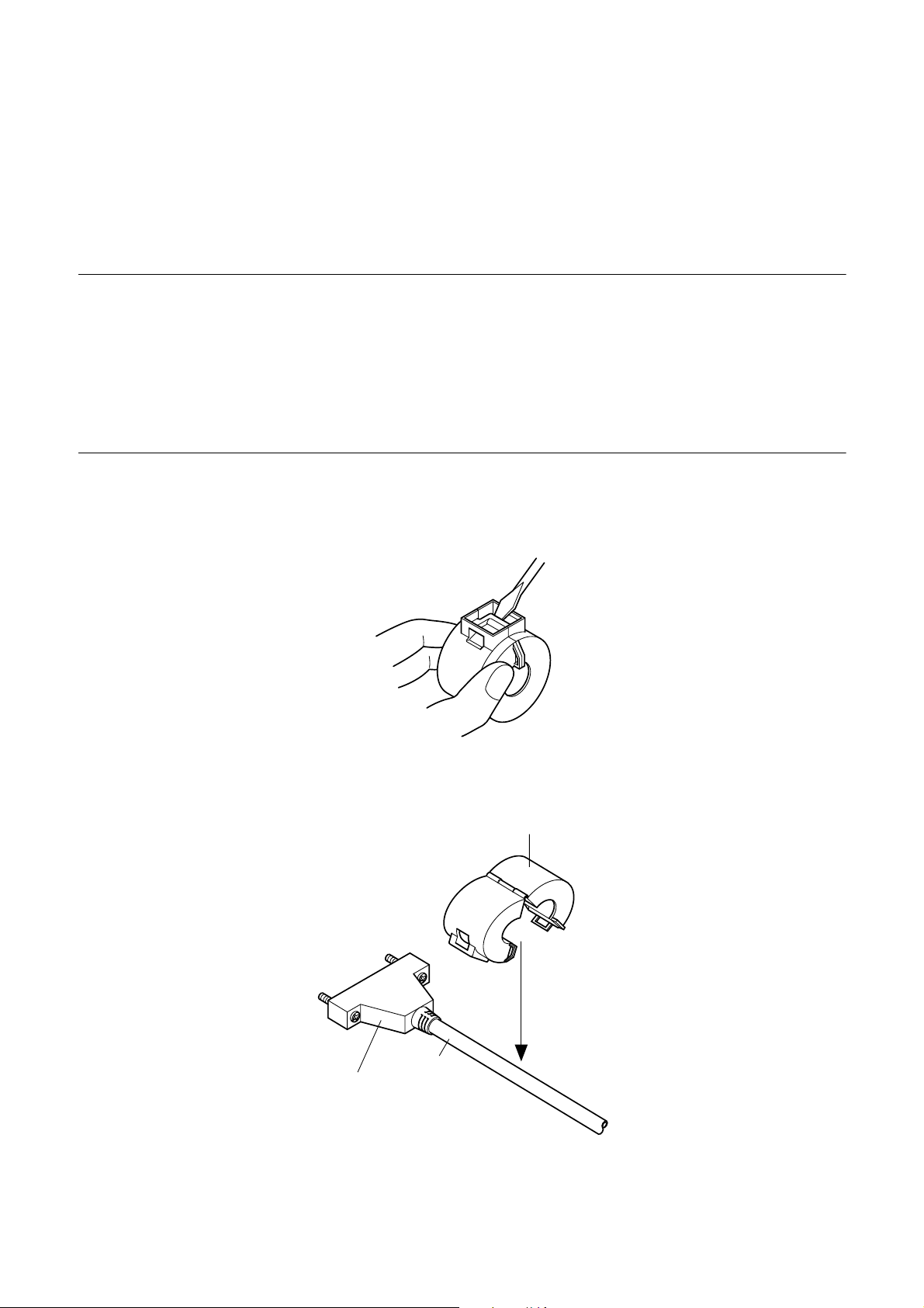
❏ Affix the larger ferrite core onto the interface cable as shown in the
illustration below.
Interface
Ferrite core (28 mm diameter)
Cable
– 13 –
Page 28
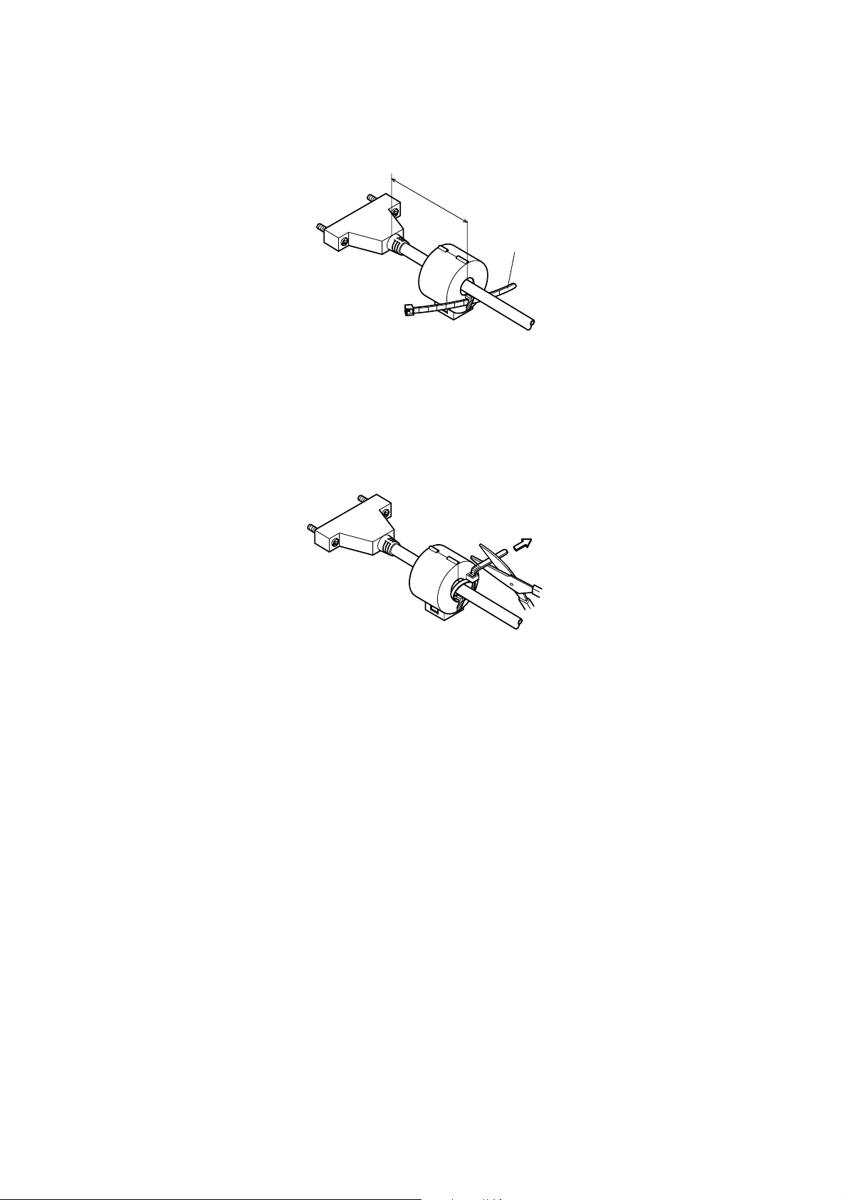
Pass the fastener through the ferrite core.
5 cm
maximum
Fastner
Loop the fastener around the cable and lock it. Use scissors to cut off any
excess.
Pull and cut
❏ Plug one end of the serial cable into the serial port of your computer, and
the other end of the cable into the socket on the back of the printer. Secure
both connectors in place with the screws that are provided.
– 14 –
Page 29
4.6 Connecting to a peripheral unit
You can connect a peripheral unit to the printer using a modular plug. The
following describes how to install the ferrite core and make the actual
connection. See “Modular plug” on page 31 for details about the type of
modular plug that is required. Note that this printer does not come with a
modular plug or wire, so it is up to you to obtain one that suits your needs.
Important!
Make sure that the printer is turned off and unplugged from the AC outlet and
that the computer is turned off before making connections.
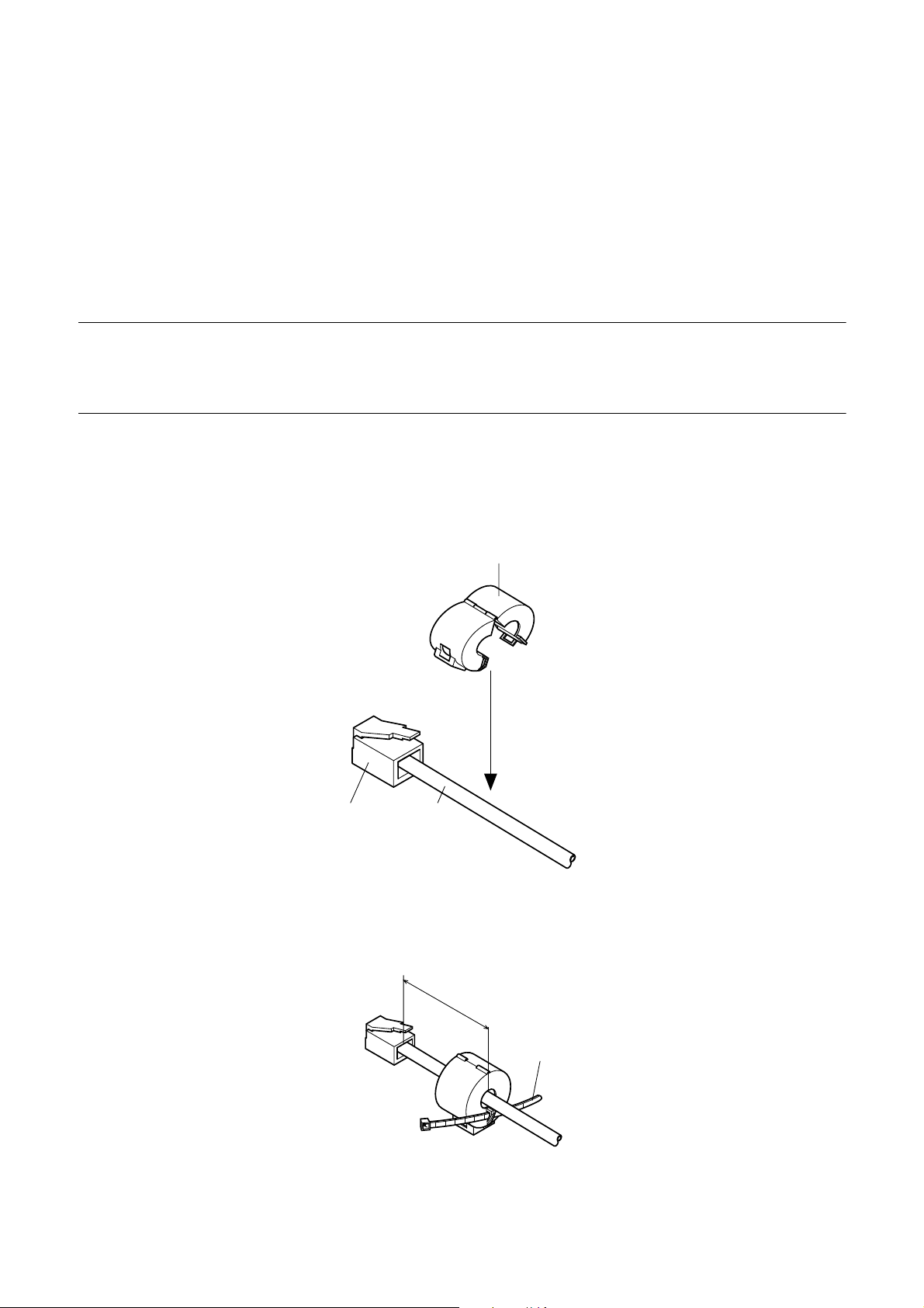
❏ Affix the smaller ferrite core onto the modular wire as shown in the
illustration below.
Ferrite core (20 mm diameter)
Connector
Cable
Pass the fastener through the ferrite core.
5 cm
maximum
Fastner
– 15 –
Page 30

Loop the fastener around the cable and lock it. Use scissors to cut off any
excess.
❏ Plug one end of the modular cable into the modular jack of the peripheral.
❏ Remove the modular jack cover from the back of the printer and plug the
other end of the modular cable into the jack of the printer.
4.7 Inserting the paper into the printer
Use only the specified type of paper for this printer. Do not use inappropriate
types of paper, or it could cause malfunction or damage of the printer.
Pull and cut
The following procedure describes how to print on paper. Before trying to print,
be sure to install a ribbon cassette into the printer using the procedure under
“Installing the ribbon cassette” on page 9.
❏ Make sure that the printer is plugged in and turned on.
❏ Check that the RELEASE indicator on the control panel is lit. If the
Important!
Insertion and removal of paper should be done only when the printer is
released condition (the paper is not held by paper feed roller).
indicator is not lit, press the RELEASE button until the indicator lights up.
– 16 –
Page 31

❏ Place a piece of the paper onto the printer’s document table and slide its
right edge into the printer. Printing will be performed on the side of the
paper that is facing up (the one you can see), starting from the top of the
paper.
Important!
Do not use wrinkled or curled paper. In case of multiple paper, neatly align the
sheets.
Though paper can be inserted either from the front or side of the printer, front
paper insertion may result in paper jams, depending on the condition of the
paper. Because of this, it is recommended that you always insert paper from the
side.
4.8 AutoSide Loading™
This printer is equipped with paper sensors, so you do not have to perform any
special procedure to align the location from which printing should start. Simply
insert the paper into the printer and the sensor locates the top of the paper. The
paper will be moved automatically into position for printing.
Important!
When inserting the paper into the printer, make sure that there are at least 3 cm
between the top edge of the paper and the print start position mark on the
printer. Otherwise the paper sensor may not be able to correctly locate the top
of the paper.
At least 3 cm
Print start position mark
– 17 –
Page 32

❏ Push the right edge of the paper into the printer until it stops. At that time,
the PAPER OUT indicator will go out, and the printer mechanism will
automatically align the paper for printing from the top.
❏ Send data from your host computer to be printed on the paper.
❏ After printing, press the RELEASE button to automatically release the
paper.
– 18 –
Page 33

4.9 Control Panel Operations
The control panel gives you some push-button control over the slip printer
operation. It also includes indicator lights, which tell you the current status of
the printer at a glance.
POWER
RELEASE
FORWARD
PAPER
OUT
REVERSE
RELEASE
4.9.1 Indicator lights
The following table describes the meaning of indicator lights when it is on, off,
or flashing.
Indicator Light Off On Flashing
POWER
PAPER OUT
Power off Power on Dot Alignment Adjust
Paper inserted No paper Insert paper prompt
Mode
RELEASE
4.9.2 Buttons
The following table describes the function of the three control buttons of the
control panel.
Button Description
FORWARD
REVERSE
RELEASE
Slip paper engaged Slip paper released Mechanical error
Feeds the slip paper forward, toward the back of the printer. One press
feeds one line, holding down performs continuous feed.
Feeds the slip paper back, toward the front of the printer. One press
feeds one line, holding down performs continuous feed.
Activates the printer's paper release (the paper is not held in place by
the paper feed roller).
Clears recoverable errors.
– 19 –
Page 34

4.9.3 Producing a test print
The following procedure can be used at any time to test the printer.
❏ Turn on the printer and insert a piece of paper (page 11, 16).
❏ Turn off printer power.
❏ While holding down RELEASE, turn printer back on. Keep RELEASE
depressed for a few moments until the printer beeps and the printer test
print starts.
The printer test will continue until it reaches the end of the paper.
4.9.4 Adjusting the dot alignment
You may never have to use the procedure described in this section, but after you
have been using your printer for some time you may find that the dots of some
graphics do not align correctly. For example, what should look like:
may come out looking like one of the following:
or like this
– 20 –
Page 35

This is caused when mechanical parts of the printer get out of alignment. This
happens only rarely and you may never experience it at all throughout the life
of the printer. If you do have problems, use the following procedure to correct it.
❏ Turn on the printer and insert a piece of paper.
❏ Turn off printer power.
❏ While holding down the control panel’s FORWARD and REVERSE
buttons, turn the printer back on to enter the Dot Alignment Adjust Mode,
which is indicator by a flashing POWER indicator flashes.
Entering the Dot Alignment Adjust Mode causes seven blocks to be printed,
each of which indicates a dot alignment setting, as shown below. An asterisk
to the left of the blocks indicates which block is currently selected.
❏ Use FORWARD to specify the block that appears to have the best aligned
characters. Press FORWARD once to specify the first block, twice to
specify the second block, and so on up to seven times to specify the seventh
block.
Warning beep will sound if you press FORWARD more than seven times.
❏ After specifying a block, press REVERSE to register your selection and
exit the Dot Alignment Adjust Mode.
– 21 –
Page 36

Note:
The dots alignment adjustment setting you selected is stored in printer memory
and a pattern is printed using the selected setting followed by the message
“Adjust Complete!” The printer ejects the paper after printing is complete.
You setting is not registered if you turn off printer power before pressing
REVERSE to exit the Dot Alignment Adjust Mode.
If a paper feed error occurs during this mode, the printer ejects the paper and
this mode is cancelled.
4.9.5 Hexadecimal dump
This procedure prints in hexadecimal format all codes (character codes and
control codes) that are sent to the printer by the computer. The printer does not
execute any control codes (such as 0A - linefeed), it just prints them out. The
hexadecimal dump is useful when you are writing programs for printer control.
❏ Turn on the printer and insert a piece of paper.
❏ Turn off printer power.
❏ While holding down the control panel’s FORWARD buttons, turn the
printer back on to enter the Hex Dump Mode.
❏ To exit the Hex Dump Mode, turn the printer off.
Note:
The printer will not responde to any commands you send it while it is in the
Hex Dump Mode.
– 22 –
Page 37

4.9.6 Errors
There are three types of errors: recoverable errors that require some action by
you before they clear, non-recoverable errors that require servicing by an
authorized service provider, and a data receive error. Errors are indicated by and
audible buzzer and the indicators.
(1) Recoverable Errors
Error Type
Paper jam
Indicators
Recovery
POWER RELEASE PAPER OUT
Carriage motor lockup
Abnormal home position signal
Abnormal timing signal
(2) Non-recoverable Errors
Error Type
POWER RELEASE PAPER OUT
RAM read/write
Off On On
CPU lockup
(3) Data Receive Error
This type of error is caused whenever a problem is encountered during data
receipt. The method used by the printer to recover from a data receive error
depends on the current command mode.
Flashing
Indicators
Correct the cause of the problem and
then press RELEASE.
Recovery
Turn off the printer, then after waiting a
few minutes, turn the printer back on. If
the printer does not recover, contact
your nearest service provider.
Data Receive Error Recover Procedure
Memory switch 4-0=0 : The printer prints a question mark.
Memory switch 4-0=1 : The printer discards the received data.
– 23 –
Page 38

4.10 Paper Sensors
The following paper sensors are available.
❏ TOF Sensor
This top-of-form sensor detects the leading edge of the paper.
When enabled, the TOF sensor detects when there is no paper present and
stops printing.
❏ BOF Sensor
This bottom-of-form sensor detects the trailing edge of the paper. When
enabled, the BOF sensor detects when there is no paper present and printing
is interrupted.
When the TOF or BOF sensor detects that no paper is present, the printer stops
its motor after printing of 0 to a maximum of two more lines.
The BOF sensor detects a paper out condition whenever the distance between
print head pin #9 and the trailing edge of the paper becomes 38.1 mm or less.
The print stop operation is not entered until the distance between print head pin
#9 and the trailing edge of the paper becomes 27.3 mm or less.
When the auto clamp is enabled with Memory Switch 5-1, the auto clamp
operation is performed about 1.0 second (Initial value is approximately
1 second) after the presence of paper is detected both by the TOF and BOF
sensors, following a paper out condition. The auto clamp function is not affected
by whether the TOF or BOF sensor is enabled or disabled.
The top of form positioning function is enabled with Memory Switch 5-0. Even
if the auto clamp function is disabled, auto top of form positioning is performed
if the paper is clamped when printing starts.
The PAPER OUT lamp flashes to request insertion of paper when the sensors
detect there is no paper (when a sensor enabled by command detects no paper)
after data is received by the printer. At that time, the user inserts paper, and
printing begins after the sensor detects that paper is present.
– 24 –
Page 39

5. Making DIP Switch Settings
The printer’s DIP switches let you specify communications parameters, receive
buffer size, and emulation. This “5. Making DIP Switch Settings” explains the
settings you can make and tells you how to actually change DIP switch settings.
5.1 Accessing the DIP switches
The DIP switches are located inside the printer, underneath the document table.
Use the following procedure to remove the document table so you can operate
the DIP switches.
❏ Make sure that the printer is turned off and unplugged from its wall outlet.
❏ Remove the printer cover.
❏ While using a screwdriver or other similar instrument to press down at the
location marked (a) in the illustration below, carefully slide the document
table in the direction indicated by the arrow until it is out of the way.
a
– 25 –
Page 40

It is not necessary to remove the document table completely, just move it
enough so you can get at the DIP switches inside.
ON
OFF
ON
Note:
Note:
12345678910
OFF
If the document table seems to be getting caught on the rollers, it means that
you are not pressing down at point (a) enough. Pressing at point (a) should
separate the rollers to the document table can slide freely.
❏ After the document table is opened sufficiently, use a thin flat-blade
screwdriver or some other similar object to change DIP switch settings.
See the following section for details on available DIP switch settings.
❏ After making the settings you want, slide the document table back into
place while pressing down at point (a). Make sure that the document table
is correctly seated in place before releasing point (a).
❏ Replace the printer cover.
– 26 –
Page 41

5.2 Available DIP switch settings
The following table shows all the possible settings for the DIP switch. The
factory default settings are ON for switches 1 through 7 and OFF for switches
8 through 10.
Switch Parameter ON OFF
1
Baud Rate See table below
2
3 Data Length 8 bits 7 bits
4 Parity Check Disabled Enabled
5 Parity Odd Even
6 Handshake DTR/DSR XON/XOFF
7 Receive Buffer Size 2K bytes 35 bytes
8 Character Code Set Japanese (Katakana) International (PC437)
9 Pin 6 (DSR) Reset Signal Enabled Disabled
10 Pin 25 (INIT) Reset Signal Enabled Disabled
Baud Rate Switch 1 Switch 2
1200BPS OFF OFF
2400BPS ON OFF
4800BPS OFF ON
9600BPS ON ON
– 27 –
Page 42

5.3 Memory Switch Settings
Each memory switch is a 16-bit word store in EEPROM. For details on the
functions and settings of memory switches, see the “9. Print Control Functions
(ESC#)”.
The table below shows the factory settings for the memory switches.
Memory Switch Hexadecimal Code
# 0 –
# 1 –
# 2 –
# 3 –
# 4 0000
# 5 0000
Warning!
Changing the memory switch settings can cause the printer to fail to operate
correctly.
– 28 –
Page 43

6. Interface
This appendix provides detailed specifications for the printer’s standard serial
interface.
13
25
6.1 Pins and Signal Names
Pin
No.
Signal
Name
1 FG — Frame ground
2 TXD OUT Transmission data
3 RXD IN Receive data
4 RTS OUT Same as DTR signal
Direction Function
1
14
5 N.C. Not connected
6 DSR IN • DIP Switch 9 = OFF
In DTR/DSR communication mode when Memory Switch4-5 = 0, indicates whether data
receive from host is enabled or disabled.
Space: Receive enabled
Mark: Receive disabled
This signal is not checked in the X-ON/X-OFF communication mode.
• DIP Switch 9 = ON
This signal used for external reset. Printer is reset whenever signal is in mark state with
pulse width of 1mS or more.
7 SG Signal ground
8 -19 N.C. Not connected
– 29 –
Page 44

Pin
No.
21 - 24 N.C. Not connected
Signal
Name
20 DTR OUT Indicates whether data receive from host is enabled or disabled.
25 INIT IN • DIP Switch 10 = OFF
Direction Function
DTR/DSR Communication Mode
Space when receive is enabled.
X-On/X-Off Communication Mode
Always space, except during following conditions:
• Period between reset and communication enabled
• During self-test printing and dot alignment adjustment
This signal not used.
• DIP Switch 10 = ON
This signal becomes reset signal. Printer is reset whenever signal is in mark state with
pulse width of 1mS or more.
6.2 Interface Connections
Refer to the interface specifications of the host for details on connecting to its
interface connector. The following illustration shows a typical connection
configuration.
(D-sub 25 pin)
F-GND
TXD
RXD
RTS
DSR
S-GND
DTR
INIT
Printer side
1
2
3
4
6
7
20
25
IBM PC side
1
2
3
4
5
6
7
8
20
9 pin25 pin
3
2
7
8
6
5
1
4
F-GND
TXD
RXD
RTS
CTS
DSR
S-GND
DCD
DTR
– 30 –
Page 45

7. Peripheral Unit Driver Circuit
This printer is equipped with a circuit for driving peripheral units, such as cash
drawers. A 6-pin modular connector for connection of the peripheral unit is
located on the back of the printer. To connect to the drive circuit, connect the
peripheral unit to the modular connector using a cable supplied by you like that
one shown in the figure below.
Important!
Never connect any other type of plug to the peripheral unit connector.
7.1 Modular plug
Modular plug: MOLEX 90075-0007,
AMP641337, or JAPAN BURNDY B-66-4
Shield
16
Wire lead
– 31 –
Page 46

7.2 Drive circuit
The recommended drive unit is shown below.
Drive output: 24V, 1.0A max.
F.G
TR1
M-GND
TR2
M-GND
TR3
+5V
+24V
R2
R1
1
2
D1
7824
D2
Printer side User side
3
4
5
6
With shield
L1
L2
Peripheral
unit 2
Frame
ground
Peripheral
unit 1
R3
4.7kΩ
1/4W
Compulsion
switch
Notes
• Peripheral Units 1 and 2 cannot be driven simultaneously.
• For continuous driving, do not use drive duty greater than 20%.
• Compulsion switch status is available as status data.
• Minimum resistance for coils L1 and L2 is 24Ω.
• Absolute maximum ratings for diodes D1 and D2 (Ta = 25°C) are:
Average Rectified Current Io = 1A
Maximum forward surge current (60Hz, 1-cycle sine wave) I
FSM
= 40A
• Absolute maximum rating for transistors TR1 and TR2 (Ta = 25°C) are:
Collector current Ic = 2A
Collector loss Pc = 1.2W
– 32 –
Page 47

8. Maintenance and Service
For the information on maintenance and service, please contact our dealer or at
the following address.
North America Other Areas
CBM America Corporation Japan CBM Corporation
Service Center Information Systems Division
365 Van Ness Way CBM Bldg., 5-68-10, Nakano,
Suite 510 Nakano-ku, Tokyo 164-0001
Torrance, CA 90501, U.S.A Japan
TEL +1-310-781-1460 TEL +81-3-5345-7540
FAX +1-310-781-9157 FAX +81-3-5345-7541
– 33 –
Page 48

9. Print Control Functions
This printer supports one command mode: the ESC/POS mode.
The ESC/POS mode emulates the Epson TM-295 slip printer.
This chapter provides you with all of the commands supported by this printer.
9.1 List of ESC/POS Commands
Command Function Code
HT Horizontal Tab 09H 37
LF Line Feed 0AH 37
FF Prints and Ejects Single Sheet, and Prints and
Returns in Paper Mode
DLE EOT Sends Status at Real Time 10H 04H n 39
CAN Cancels Print Data in Page Mode 18H Disabled 42
ESC SP Sets Space Size to Right of Characters 1BH 20H n 42
ESC ! Selects Print Mode in Batch 1BH 21H n 43
ESC # Sets Memory Switch
(Unique Extension Command)
ESC % Selects/Deselects Download Character Set 1BH 25H n 46
ESC & Defines Download Characters 1BH 26H y c1 c2 47
ESC
ESC 2 Sets 1/6-inch Line Feed 1BH 32H
Selects Bit Image Mode 1BH 2AH m
0CH
1BH 23H N
n1 n2 n3 n4
Standard
Mode
44
49
51
Page
Mode
Page
38
ESC 3 Sets n/60-inch Line Feed (Approximate Value) 1BH 33H n
ESC = Selects Peripheral Device 1BH 3DH n
ESC @ Initializes Printer 1BH 40H
ESC C Sets Single Sheet Ejection Length 1BH 43H
ESC D Sets Horizontal Tab Position 1BH 44H
ESC F Selects/Deselects Ejection of Single Sheet in
Reverse Direction
ESC J Print and n/60-inch Paper Feed
(Approximate Value)
ESC K Print and n/60-inch Reverse Paper Feed
(Approximate Value)
ESC L Selects Page Mode 1BH 4CH n (Line) Disabled 57
ESC R Selects International Characters 1BH 52H n
ESC T Selects Character Print Direction in Page Mode 1BH 54H n (Set)
1BH 46H n
1BH 4AH n
1BH 4BH n
51
52
53
53
54
55
55
Disabled 56
58
59
– 34 –
Page 49

Command Function Code
Standard
Mode
Page
Mode
Page
ESC W Sets Print Area in Page Mode 1BH 57H (Set)
ESC c4 Selects No-paper Sensor Valid for Print Stop 1BH 63H 34H n
ESC c5 Enables/Disables Panel Switch 1BH 63H 35H n
ESC d Print and N-line Paper Feed 1BH 64H n
ESC e Print and N-line Reverse Paper Feed 1BH 65H n
ESC f Sets Single Sheet Waiting Time 1BH 66H t1 t2
ESC p Generates Specified Pulses 1BH 70H m t1 t2
ESC q Release 1BH 71H
ESC t Selects Character Code Table 1BH 74H n
ESC u Sends Peripheral Device Status 1BH 75H n
ESC v Sends Paper Sensor Status 1BH 76H
ESC { Selects/Deselects Inverted Print 1BH 7BH n (Line) (Set) 69
GS I Sends Printer ID 1DH 49H n
GS a Enables/Disables Automatic Status Sending 1DH 61H n
GS r Sends Status 1DH 72H n
61
62
62
Disabled 63
63
64
Disabled 65
66
67
68
70
71
74
60
: Enabled
(Line) : Enabled only at the head of the line
(Set) : Only setting is enabled
: Only part of setting is enabled
: Ignores partially Disabled: An argument is processed as next data
– 35 –
Page 50

9.2 Command Details
9.2.1 Description of Each Items
XXXX
[Function] Shows a command function.
[Code] Shows a sequence of code consisting the command; ASCII represents the ASCII code and [ ]k
a repeat count of k-times.
[Range] Shows a settable range of an argument.
[Outline] Outlines the command.
[Caution] Describes a caution for the command as required.
[Default] Describes an initial value for the command, if accompanied by an argument.
[See Also] Describes other associated commands in using the command.
[Example] Describes an example of using the command.
< >H: Denotes a hexadecimal number.
< >B: Denotes a binary number. < >: Denotes a decimal number.
Notes Of "Enabled only at the head of the line" in Section 9.1, the "head of the line" refers to the
case when the following condition is satisfied.
(1) There is no print data (space and skipping portion by HT included) in the current
print buffer.
– 36 –
Page 51

9.2.2 Command Details
HT
[Function] Horizontal Tab
[Code] ASCII HT
Hexadecimal 09
Decimal 9
[Outline] This command shifts a printing position to the next horizontal tab position.
[Caution] • The horizontal tab position is set by ESC D.
• The command is ignored if the next horizontal tab position has not been set.
• Initial setting of the horizontal tab position is every 8 characters of the 5 × 7 font(9th, 17th,
25th character, and so on)
[See Also] ESC D
LF
[Function] Line Feed
[Code] ASCII LF
Hexadecimal 0A
Decimal 10
[Outline] This command prints the data in the print buffer and feeds the paper by a set line feed amount.
[Caution] • The head of the line is assumed to be the next printing start position.
[See Also] ESC 2, ESC 3
– 37 –
Page 52

FF
[Function] Prints and Ejects Single Sheet, and Prints and Returns in Paper Mode
[Code] ASCII FF
Hexadecimal 0C
Decimal 12
There is the following difference between the standard mode and page mode:
<Standard Mode>
[Outline] This command prints the data in the print buffer and ejects a single sheet.
[Caution] • If a single sheet ejection length by ESC C has not been set, the paper will be ejected
completely. If it has been set, the paper will be ejected by a set amount. If the no-paper
condition is detected halfway ejection, the printer will stop paper ejection even before
reaching the set ejection amount.
• The single sheet ejecting direction is specified by ESC F.
[See Also] ESC F, ESC C
<Page Mode>
[Outline] Prints in batch the data developed across the print area and returns to the standard mode.
When this is done, all the developed data are erased after printing. The paper is not ejected.
[Caution] • The head of the line is assumed to be the next printing position.
[See Also] ESC L
– 38 –
Page 53

DLE EOT n
[Function] Sends Status at Real Time
[Code] ASCII DLE EOT n
Hexadecimal 10 04 n
Decimal 16 4 n
[Range] 1 n 3, n = 5
[Outline] This command sends the n-specified status at real time.
n Description
1 Sends the printer status.
2 Sends the off-line factor status.
3 Sends the error factor status.
5 Sends the slip status.
[Caution] • For the status sent, see the tables on the following pages.
• This command runs processing upon its reception.
• When sending the status, only one byte is sent without confirming the DSR signal status.
• The command is executed in the off-line state, reception buffer full state, and error state as
well.
• The user should note that the operation of this command is also executed when a data
sequence of <10>H<04>H<n> (1 n 3, n = 5) is received, other than this command.
<Example>
d1 = <10>H, d2 = <04>H, d3 = <1> in ESC * m nL nH [d]nL + 256 × nH
• This command must not be used by interrupting the code sequence of other command
consisting of 2 bytes or more.
<Example>
If DLE EOT 3 is sent after sending up to ESC 3, attempting to send ESC 3 n from the host, it
will be processed as ESC 3 n = <10>H. Therefore, the use should take heed of this.
• If ASB has been enabled by GS a, it is necessary to distinguish the status by this command
from that of ASB. See “6. Interface” for how to distinguish them
• If n is beyond the range, this command will be ignored.
– 39 –
Page 54

n = 1: Printer status
Bit Description Hexadecimal Decimal
0 Unused 00 0
1 Unused 02 2
2 Status of the drawer kick connector No. 3 pin = L 00 0
Status of the drawer kick connector No. 3 pin = H 04 4
3 On-line status 00 0
Off-line status 08 8
4 Unused 10 16
5 Undefined – –
6 Undefined – –
7 Unused 00 0
n = 2: Off-line factor status
Bit Description Hexadecimal Decimal
0 Unused 00 0
1 Unused 02 2
2 Undefined – –
3 Not feeding the paper by the Paper Feed switch 00 0
Feeding the paper by the Paper Feed switch 08 8
4 Unused 10 16
5 No print stop because of no paper. 00 0
Print stop because of no paper. 20 32
6 No error 00 0
Error 40 64
7 Unused 00 0
Bit 5 : If there is no paper when the TOF or BOF sensor enables no-paper print stop by ESC c 4, the printer
will stop printing, resulting in 32 (print stopping).
– 40 –
Page 55

n = 3: Error factor status
Bit Description Hexadecimal Decimal
0 Unused 00 0
1 Unused 02 2
2 Undefined – –
3 Undefined – –
4 Unused 10 16
5 No irrecoverable error 00 0
Irrecoverable error 20 32
6 Undefined – –
7 Unused 00 0
n = 5: Slip status
Bit Description Hexadecimal Decimal
0 Unused 00 0
1 Unused 02 2
2 The slip has been selected 00 0
3 Slip insertion non-waiting status 00 0
Slip insertion waiting status 08 8
4 Unused 10 16
5 Paper set in the BOF sensor 00 0
No paper set in the BOF sensor 20 32
6 Paper set in the TOF sensor 00 0
No paper set in the TOF sensor 40 64
7 Unused 00 0
Bit 3 : Detects a slip of paper and results in 0 immediately before starting the operation (not waiting for
insertion)
Bits 5, 6 : Send the current status of the TOF and BOF sensors.
[See Also] ESC u, ESC v, GS a, 6. Interface
– 41 –
Page 56

CAN
[Function] Cancels Print Data in Page Mode
[Code] ASCII CAN
Hexadecimal 18
Decimal 24
[Outline] This command erases all the print data in the current print area in the page mode.
[Caution] • This command is valid only in the page mode.
• Even the print data in the previously set print area is erased, if it is extended over the
currently set print area.
[See Also] ESC W
ESC SP n
[Function] Sets Space Size to Right of Characters
[Code] ASCII ESC SP n
Hexadecimal 1B 20 n
Decimal 27 32 n
[Range] 0 n 32
[Outline] This command sets the right space size of the characters.
[Caution] • In the double width mode, the right space size is doubled.
• The space size is set in increments of half dot.
• In the page mode, the space size may be shifted a half dot from a set value.
• There are two set values for the standard and page modes, respectively.
[Default] n = 0
– 42 –
Page 57

ESC ! n
Bit Description Hexadecimal Decimal
0 Character font 5 × 7000
Character font 7 × 7011
1 Undefined – –
2 Undefined – –
3 Undefined – –
4 Deselects double height 00 0
Selects double height 10 16
5 Deselects double width 00 0
Selects double width 20 32
6 Undefined – –
7 Deselects underline 00 0
Selects underline 80 128
[Function] Selects Print Mode in Batch
[Code] ASCII ESC ! n
Hexadecimal 1B 21 n
Decimal 27 33 n
[Range] 0 n 32
[Outline] This command specifies the print mode.
Each bit has the following meaning.
[Caution] • The underline is drawn across the print character width, not the blank skipped by HT.
• If both double height and double width are specified, the characters will be quadrupled.
• For selection of the underline and 7 × 7 font in the page mode, only their setting is enabled.
[Default] n = 0
– 43 –
Page 58

ESC #
[Function] Sets Memory Switch
[Code] ASCII <ESC>"#N, n1 n2 n3 n4" <LF> <NUL>
Hexadecimal 1B 23 N 2C n1 n2 n3 n4 0A 00
Decimal 27 35 N 44 n1 n2 n3 n4 10 0
N : Memory switch segment number (4 and 5 only)
n1 n2 n3 n4: Set data
[Range] N="4"(34h) or "5"(35h)
"0"(30h) n1,n2,n3,n4 "9"(39h) or "A"(41h) n1,n2,n3,n4 "F"(46h)
[Outline] The memory switch is stored in the nonvolatile EEPROM memory. To change this setting, send
a command from the host side. After setting with the command, turn on the power again, or
reset with the following reset command, to enable setting. (If reset with the command, self-
printing will be implemented.)
Reset command: <ESC> <CAN> <LF> <NUL>
[Caution] The EEROM has a data-writing life. Do not execute this command every time. Note that if the
EEROM’s life is running out due to frequent use of this command, printer operation cannot be
guaranteed.
The memory switch segment numbers other than 3 to 5 do not have relevant setting items, but
they actually exist. Therefore, use of other numbers besides 3 to 5 will be valid as a command
and change the data in the EEROM. If this is the case, operation will not be guaranteed.
Exercise full care when using this command.
1) Memory Switch 4 (MSW4)
The setting upon shipment from the factory is indicated with “
Bit Description 0 1
F
n1 E
D
(LSB) C
B
n2 A
9
(LSB) 8
7
n3 6
5 DSR signal check at status sending time Checks
(LSB) 4
3
n4 2
1
(LSB) 0 Data reception Prints "?"
*
”.
*
*
Does not check
Ignores
( : Denotes setting enabled)
(Note) X-ON/X-OFF output timing: Setting whether to output the X-ON code every 3 seconds
– 44 –
Page 59

”.
2) Memory Switch 5 (MSW5)
The setting upon shipment from the factory is indicated with “
*
Bit Description
F
n1 E
D <ESC> "q" command function See Table below
(LSB) C <ESC> "q" command function See Table below
B
n2 A
9
(LSB) 8
7
n3 6
5
(LSB) 4
3
n4 2
1 Automatic clamp function Enabled
(LSB) 0 Automatic head search function Enabled
00
00
*
*
Disabled
Disabled
1111
MSW5-D MSW5-C <ESC> “q” Command Function
*
0
1 0 Implements releasing
0 1 Implements releasing after discharging all in the forward direction
1 1 Implements releasing after discharging all in the reverse direction
*
0
Implements releasing
(far side).
(near side).
*
– 45 –
Page 60

ESC % n
[Function] Selects/Deselects Download Character Set
[Code] ASCII ESC % n
Hexadecimal 1B 25 n
Decimal 27 37 n
[Range] 0 n
[Outline] This command selects or deselects the download character set. n is valid only for the least
significant bit.
• At n = <
• At n = <
[Default] n = 0
[See Also] ESC &
255
internal character set).
0>B, the command deselects the download character set(selects an
1>B, the command selects the download character set.
– 46 –
Page 61

ESC & y c1 c2 [x[d]yxx]c2-c1+1
[Function] Defines Download Characters
[Code] ASCII ESC & y c1 c2 [x [d] y
Hexadecimal 1B 26 y c1 c2 [x [d] y
Decimal 27 38 y c1 c2 [x [d] y × x ] c2-c1+1
[Range] y = 1
32 c1 c2 126
0 x 6 (When the 5 × 7 font is selected)
0 x 10 (When the 7 × 7 font is selected)
0 d1 ... d y × x 255
[Outline] This command defines the font of the alphanumeric or Kana download characters.
• y denotes the number of vertical bytes.
• c1 denotes the start character code and c2, end character code, respectively. When defining
only one character, set c1 = c2.
• The definable character code is the 95 ASCII code characters from <20>H to <7E>H.
• x denotes the number of horizontal dots to be defined.
• d denotes the data to be defined; a horizontal x dots pattern from the left. The right
remaining pattern results in spaces.
[Caution] • Once the download characters are defined, they will remain valid until they are redefined,
ESC @ is executed, the printer is reset, or the power is turned off.
• If y, c1, c2, or x is beyond the range, this command will be ignored, processing the
subsequent data as normal one.
• In case of the 7 × 7 font, define the data so that the horizontally adjacent dots will not be
contained, because they cannot be printed.
×
x ] c2-c1+1
× x ] c2-c1+1
[Default] Identical pattern with the internal character set
[See Also] ESC %
– 47 –
Page 62

[Example]
• When selecting the 5 × 7 font
p1 p2 p3 p4 p5 p6
When defining the pattern above to the code 20H
ESC& y c1c2 x p1p2p3p4p5
Code (hex.) 1B 26 01 20 20 05 3E 48 88 48 3E
MSB
LSB
• When selecting the 7 × 7 font
p1 p2 p3 p4 p5 p6 p7 p8 p9 p10
When defining the pattern above to the code 20H
ESC& y c1c2 x p1p2p3p4p5p6p7
Code (hex.) 1B 26 01 20 20 07 1E 20 48 80 48 20 1E
MSB
LSB
– 48 –
Page 63

ESC * m nL nH [d]k
*1: The total number of horizontal dots in the page mode differs depending on the printing area
secured with ESC W and printing direction specified with ESC T.
m Mode
Vertical Direction Horizontal Direction (*1)
Dots Max. Dots
0 8-dots single density 8 210
1 8-dots double density 8 420
[Function] Selects Bit Image Mode
[Code] ASCII ESC * m nL nH [d] k
Hexadecimal 1B 2A m nL nH [d] k
Decimal 27 42 m nL nH [d] k
[Range] m = 0, 1
0 nL 255
0 nH 3
0 d 255
k = nL nH × 256
[Outline] • This command specifies the bit image of the m-mode as to the number of dots specified with
nL and nH.
• nL and nH denote the number of horizontal dots of the bit image to be printed, resulting in [nL
+ nH × 256] dots.
• If the bit image data is input beyond the dot position printable in one line, the surplus data will
be discarded.
• d denotes the bit image data. Set "1" in the corresponding bit when printing, and "0" when
not printing.
• The following table lists the bit image mode selected with m.
[Caution] • If a value of m or nH goes beyond the range, this command will be ignored, processing the
subsequent data as normal one.
• Normal data processing is restored after printing the bit image.
• The following page shows the relations between the bit image data and the dots printed.
• The double density bit image is invalidated in the page mode.
– 49 –
Page 64

• The following shows the relations between the bit image data and the dots printed.
76543210
Bit Image Data
High
Low
Print Data
– 50 –
Page 65

ESC 2
[Function] Sets 1/6-inch Line Feed
[Code] ASCII ESC 2
Hexadecimal 1B 32
Decimal 27 50
[Outline] This command sets a line feed amount per line to 1/6 inch.
[Caution] There are two kinds of line feed amounts for the standard mode and page mode.
• For the standard mode: Set to 1/6 inch.
• For the page mode: Set to 10 dots (10/72 inch)
[See Also] ESC 3
ESC 3 n
[Function] Sets Line Feed Amount
[Code] ASCII ESC 3 n
Hexadecimal 1B 33 n
Decimal 27 51 n
[Range] 0 n 255
[Outline] This command sets a line feed amount per line to n/60 inch.
[Caution] There are two kinds of set values for the standard mode and page mode. Since the printer has
the minimum paper feed pitch of 1/144 inch, the line feed amount of n/60 inch is treated as
follows:
• For the standard mode: Set an approximate value of INT((6n+5)+0.5)/72 inch.
• For the page mode: Set n/72 inch(n coordinate).
[Default] n = 10 (1/6 inch for the standard mode and 10 dots (10/72 inch for the page mode))
[See Also] ESC 2
– 51 –
Page 66

ESC = n
Bit Peripheral Device Hexadecimal Decimal
0 Printer Disabled 00 0
Printer Enabled 01 1
1 Undefined – –
2 Undefined – –
3 Undefined – –
4 Undefined – –
5 Undefined – –
6 Undefined – –
7 Undefined – –
[Function] Selects Peripheral Device
[Code] ASCII ESC = n
Hexadecimal 1B 3D n
Decimal 27 61 n
[Range] 0 n 3
[Outline] This command selects a peripheral device which validates the subsequent data, depending on
a value of n.
• Each bit has the following different meanings.
• If Printer Disabled has been selected, the printer will discard all the received data until Printer
Enabled is selected with this command.
[Caution] • Even if Printer Disabled has been selected, the printer may be made off-line by operating it.
[Default] n = 1
– 52 –
Page 67

ESC @
Fnction] Initializes Printer
[Code] ASCII ESC @
Hexadecimal 1B 40
Decimal 27 64
[Outline] This command clears the data in the print buffer to initialize various settings.
[Caution] • The setting of the DIP switch is not re-read.
• The data in the reception buffer is not cleared.
ESC C n
[Function] Sets Single Sheet Ejection Length
[Code] ASCII ESC C n
Hexadecimal 1B 43
Decimal 27 67
[Range] 0 n 127
[Outline] This command sets a single sheet ejection length to n lines.
• If n = 0, the ejection length will not be set
[Caution] • Even if the line feed amount is changed after setting the ejection length, the latter will not
change
• The ejection length set here is meaningful only when FF is executed
[Default] n = 0
[See Also] FF
– 53 –
Page 68

ESC D [n]k NUL
[Function] Sets Horizontal Tab Position
[Code] ASCII ESC D [n] k NUL
Hexadecimal 1B 44 [n] k 00
Decimal 27 68 [n] k 0
[Range] 1 n 255
0 k 32
[Outline] This command sets a horizontal tab position.
• n denotes the number of columns from the head of the line to the horizontal tab setting
position. n is equal to the setting column position - 1, and if the horizontal tab is to be set in
the 9th column, for example, set n = 8.
• k denotes the number of horizontal tab positions to be set.
• The tab position is set to the position at a distance of the character width × n from the head of
the line. This character width includes the right space size of the character, and if double
width is selected, the character width will be doubled. A horizontal magnification selection is
followed even in the page mode.
• The data, <n>k, which denotes a setting position is input in the ascending order and ends
with <00>H.
• ESC D NUL clears all the set tab positions. After clearing, HT is ignored.
[Caution] • If the data <n>k is equal to or smaller than the preceding data <n>k-1, it is assumed that
horizontal tab setting has been finished. If this is the case, the subsequent data will be
processed as normal one.
• Up to 32 tab positions can be set. The data exceeding this limit is processed as normal data.
• If HT is executed, a move to the tab position beyond the print area will be made to the
position of the print area + 1 dot.
• Even if the character width is changed after setting the horizontal tab position, the latter will
not change.
• There are two kinds of right space sizes of the characters; for the standard mode and page
mode. To set the horizontal tab position in the respective modes, set the right space size of
the characters in the very mode you are in.
[Default] Every 8 characters of the 5 × 7 font (9th, 17th, 25th character, and so on)
[See Also] HT
– 54 –
Page 69

ESC F n
[Function] Selects/Deselects Ejection of Single Sheet in Reverse Direction
[Code] ASCII ESC F n
Hexadecimal 1B 46 n
Decimal 27 70 n
[Range] 0 n 255
[Outline] This command selects or deselects single sheet ejection in the reverse direction with FF.
• n is valid only for the least significant bit.
At n = <1>B, the command selects reverse directional ejection.
At n = <0>B, the command deselects reverse directional ejection(selects
forward directional ejection).
[Default] n = 0
[See Also] FF
ESC J n
[Function] Print and Paper Feed
[Code] ASCII ESC J n
Hexadecimal 1B 4A n
Decimal 27 74 n
[Range] 0 n 255
[Outline] This command prints the data in the print buffer and feeds the paper by n/60 inch. Since the
printer has the minimum paper feed pitch of 1/144 inch, a paper feed amount of n/60 inch is
treated as follows:
• For the standard mode: The paper is fed by an approximate value of INT((6n+5)+0.5)/72
inch.
• For the page mode: The paper is fed by n/72 inch(n coordinate).
[Caution] The head of the line is assumed to be the next printing start position.
– 55 –
Page 70

ESC K n
[Function] Print and Reverse Paper Feed
[Code] ASCII ESC K n
Hexadecimal 1B 4B n
Decimal 27 75 n
[Range] 0 n 255
[Outline] This command prints the data in the print buffer and feeds the paper by n/60 inch in the reverse
direction. Since the printer has the minimum paper feed pitch of 1/144 inch, n/60-inch reverse
directional paper feed is treated as follows:
• For the standard mode: The paper is fed by an approximate value of INT((6n+5)+0.5)/72
inch.
[Caution] • The command is valid only in the standard mode.
• The head of the line is assumed to be the next printing start position.
• A set amount does not remain.
– 56 –
Page 71

ESC L
[Function] Selects Page Mode
[Code] ASCII ESC L
Hexadecimal 1B 4C
Decimal 27 76
[Outline] This command switches from the standard mode to the page mode.
• The page mode deploys the received data over the specified print area and prints it in batch
with the FF command. Consequently, normal print commands such as LF only deploy the
data in the printer’s memory, but not actually print it.
• The printer returns to the standard mode after printing the data in the specified print area with
FF.
[Caution] • The command is valid only when it is input at the head of the line.
• In the page mode, half dots are not used, but only normal dots. Therefore, you should take
heed in setting in increments of half dot in the standard mode.
• Only the font consisting of normal dots is valid.
• The following commands have two kinds of set values for the standard mode and page
mode:
ESC SP Sets the right space size of the characters
ESC 2 Sets the 1/6-inch line feed amount
ESC 3 Sets the line feed amount
• The following commands are ignored in the page mode:
ESC K Print and reverse directional paper feed
ESC e Print and n-line reverse directional paper feed
ESC * Specifies the double density bit image
ESC q Release
• The following commands are valid only for their setting in the page mode:
ESC { Selects/deselects the inverted characters
ESC ! Selects/deselects the 7 × 7 font and underline
• The command is valid only in the standard mode.
• ESC @ returns you to the standard mode without printing.
[Default] The standard mode has been selected.
[See Also] FF, 6. Interface
– 57 –
Page 72

ESC R n
n Character Set
0 U.S.A
1 France
2 Germany
3 England
4 Denmark I
5 Sweden
6 Italy
7 Spain
8 Japan
9 Norway
10 Denmark II
[Function] Selects International Characters
[Code] ASCII ESC R n
Hexadecimal 1B 52 n
Decimal 27 82 n
[Range] 0 n 10
[Outline] This command selects the character sets for the countries listed below, depending on a value
of n.
[Caution] If n is beyond the range, this command will be ignored.
[Default] n = 0
– 58 –
Page 73

ESC T n
[Function] Selects Character Print Direction in Page Mode
[Code] ASCII ESC T n
Hexadecimal 1B 54 n
Decimal 27 84 n
[Range] 0 n 3, 48 n 51
[Outline] This command specifies the character printing direction and start point in the page mode. The
character printing direction is specified with n.
n = 0, 48 :
n = 1, 49 :
n = 2, 50 :
n = 3, 51 :
→
↑
←
↓
(Start point at upper left: A)
(Start point at lower left: B)
(Start point at lower right: C)
(Start point at upper right: D)
A
→→→→→→→
D
→→→→→→→
Paper Feed Direction
C
→→→→→→→
B
[Caution] • If the printing direction is specified or changed, the subsequent characters will have different
printing direction and start point(upper left, lower left, lower right, or upper right), depending
on a value of n.
• Only setting is valid in the standard mode.
• If n is beyond the range, this command will be ignored.
[Default] n = 0
→→→→→→→
– 59 –
Page 74

ESC W xL xH yL yH dxL dxH dyL dyH
[Function] Sets Print Area in Page Mode
[Code] ASCII ESC W xL xH yL yH dxL dxH dyL dyH
Hexadecimal 1B 57 xL xH yL yH dxL dxH dyL dyH
Decimal 27 87 xL xH yL yH dxL dxH dyL dyH
[Range] 0 xL 255, xH = 0, 0 yL 255, 0 yH 1, 0 dxL 255, dxH = 0
0 dyL 255, 0 dyH 1 (Except dxL = dxH = 0 or dyL = dyH = 0)
[Outline] This command sets the position and size of the print area in the page mode.
• The upper left start point is represented by (x0, y0), y-directional(vertical) length by dy dots,
and x-directional(horizontal) length by dx dots.
x0 = [(xL + xH
dx = [(dxL + dxH
256)] y0 = [(yL + yH × 256)]
256)] dy = [(dyL + dyH × 256)]
(0, 0)
Printable Area on Paper
(x0, y0)
×
×
dx
dy
[Caution] • Setting beyond the printable area on the paper is automatically adjusted to the maximum
settable area, based on the effective values from xL to dyH (i.e., xL, xH, yL, yH, dxL, dxH,
dyL and dyH).
• The maximum x-directional dot in the printable area is 210.
• The maximum y-directional dot in the printable area is 480.
• When deploying the print data in the specified area, a print area length in the character
printing direction and vertical direction must be always 8 dots or more.
• Set the print area to the size fittable within the printing paper.
• If the start point (x0, y0) is beyond the printable area, this command will be ignored.
• Only setting is valid in the standard mode.
[Default] xL = xH = yL = yH = 0, dxL = 210,
dxH = 0, dyL = 224, dyH = 1
Print area
(x0+dx-1, y0+dy-1)
(209 dots, 479 dots)
[See Also] CAN, ESC L, ESC T
– 60 –
Page 75

ESC c 4 n
Bit Sensor Hexadecimal Decimal
0 Undefined ––
1 Undefined ––
2 Undefined ––
3 Undefined ––
4 TOF sensor disabled 00 0
TOF sensor enabled 10 16
5 BOF sensor disabled 00 0
BOF sensor enabled 20 32
6 Undefined ––
7 Undefined ––
[Function] Selects No-paper Sensor Valid for Print Stop
[Code] ASCII ESC c 4 n
Hexadecimal 1B 63 34 n
Decimal 27 99 52 n
[Range] 0 n 255
[Outline] • This command selects in which status of the no-paper Sensor printing should be stopped.
Each bit has the following different meanings.
[Caution] • It is possible to select multiple sensors as a printing stop condition, but if any one of them
detects the no-paper condition, the printer will stop printing.
• The printer stops printing after printing the on-going line and feeding the paper. If the panel
switch is disabled at this time, the printer will release the paper automatically and waits for
new paper to be set.
[Default] n = 0
[See Also] ESC c 5
– 61 –
Page 76

ESC c 5 n
[Function] Enables/Disables Panel Switch
[Code] ASCII ESC c 5 n
Hexadecimal 1B 63 35 n
Decimal 27 99 53 n
[Range] 0 n 255
[Outline] This command enables/disables the panel switch.
• n is valid only for the least significant bit.
At n = < 0>B, the command enables the panel switch.
At n = < 1>B, the command disables the panel switch.
[Caution] • If the panel switch is disabled with this command, all the panel switches will be disabled.
[Default] n = 0
ESC d n
[Function] Print and N-line Paper Feed
[Code] ASCII ESC d n
Hexadecimal 1B 64 n
Decimal 27 100 n
[Range] 0 n 255
[Outline] This command prints the data in the print buffer and feeds the paper by n-lines.
[Caution] • The head of the line is assumed to be the next printing start position.
• The line feed amount set with ESC 2 or ESC 3 does not change.
[See Also] ESC 2, ESC 3
– 62 –
Page 77

ESC e n
[Function] Print and N-line Reverse Paper Feed
[Code] ASCII ESC e n
Hexadecima l
Decimal 27 101 n
[Range] 0
[Outline] This command prints the data in the print buffer and feeds the paper by n-lines in the reverse
[Caution] • This command is valid only in the standard mode.
n 255
direction.
• The head of the line is assumed to be the next printing start position.
• The set amount does not remain.
1B 65 n
ESC f t1 t2
[Function] Sets Single Sheet Waiting Time
[Code] ASCII ESC f t1 t2
Hexadecimal 1B 66 t1 t2
Decimal 27 102 t1 t2
[Range] t1 = 0
0 t2 64
[Outline] This command sets the time to wait for insertion of single sheets and the time to start operation
after inserting the single sheets.
• The paper insertion waiting time shall be infinite.
• The printer starts operating t2 × 0.1 second after detecting insertion of the paper.
[Caution] • If either t1 or t2 goes beyond the range, this command will be disabled, not changing the set
values so far.
[Default] t1 = 0, t2 = 10
– 63 –
Page 78

ESC p m t1 t2
m Connector Pin
0, 48 Drawer kick connector No. 2 pin
1, 49 Drawer kick connector No. 5 pin
[Function] Generates Specified Pulses
[Code] ASCII ESC p m t1 t2
Hexadecimal 1B 70 m t1 t2
Decimal 27 112 m t1 t2
[Range] m = 0, 1, 48, 49
0 t1 255
0 t2 255
[Outline] This command outputs the signal specified with t1 or t2 to the connector pin m.
• The following table lists the types of m.
• The ON time shall be t1 × 2 mS and OFF time t2 × 2 mS, respectively.
[Caution] If m goes beyond the range, this command will be ignored, processing the subsequent data as
normal data.
[See Also] 5.3 Memory Switch Settings, 7. Peripheral Unit Driver Circuit
– 64 –
Page 79

ESC q
Memory Switch
Description
4–D 4–C
0
1
0
0
Executes a release.
0 1 Executes a release after ejecting all the paper in the forward
direction(far side).
1 1 Executes a release after ejecting all the paper in the reverse direction
(near side) (
*
1).
[Function] Release
[Code] ASCII ESC q
Hexadecimal 1B 71
Decimal 27 113
[Outline] This command executes a release. The function can be selected with the Memory switch.
*1. Do not select this setting for the bound paper, because the paper may jam if it is all ejected
in the reverse direction.
[Caution] • If the panel switch is disabled and the no-paper sensor valid for print stop detects the no-
paper condition, the printer will execute a release regardless of this command.
• This command is valid only in the standard mode.
[See Also] ESC c 4, ESC c 5
– 65 –
Page 80

ESC "t" n
n Character Type
0 Codepage PC437 (USA, European Standard)
1 Codepage Katakana (Japanese)
2 Codepage PC850 (Multilingual)
3 Codepage PC860 (Portuguese)
4 Codepage PC863 (Canadian-French)
5 Codepage PC865 (Nordic)
6 Codepage PC852 (Eastern Europe)
7 Codepage PC866 (Russian)
8 Codepage PC857 (Turkish)
9 Windows Codepage
10 Codepage PC850 (Multilingual +Euro )
[Function] Selects Character Code Table
[Code] ASCII ESC t n
Hexadecimal 1B 74 n
Decimal 27 116 n
[Range] 0 n 10
[Outline] This command selects Page-n in the Character Code List..
[Caution] • If n goes beyond the range, this command will be ignored.
• Windows Codepage will be available from ROM Version “V1.3”.
• The ROM version can be confirmed in a test print. For the test print operating method, see
“4.9.3 Producing a test print”.
[Default] n = 0
[See Also] 10. Character Codes Table
– 66 –
Page 81

ESC u n
n Connector Pin
0, 48 Drawer kick connector No. 3 pin
Bit Peripheral Device Hexadecimal Decimal
0 No. 3 pin’s level = L 00 0
No. 3 pin’s level = H 01 1
1 Undefined – –
2 Undefined – –
3 Undefined – –
4 Unused 00 0
5 Undefined – –
6 Undefined – –
7 Unused 00 0
[Function] Sends Peripheral Device Status
[Code] ASCII ESC u n
Hexadecimal 1B 75 n
Decimal 27 117 n
[Range] n = 0, 48
[Outline] This command sends the status of the connector pin n every time the command is executed.
The following lists the type of n.
[Caution] The following table describes the status sent.
• If nothing is connected to the connector, the bit 0 will be always "1".
• If DTR/DSR control is selected and the memory switch 4-5 is set to 0, the printer sends only
1 byte after confirming that the host is ready to receive (the DSR signal status is Space).
If the host is not ready (the DSR signal status is Mark), the printer will wait until it will be
ready to receive. If XON/XOFF control is selected or the memory switch 4-5 is set to 1, the
printer will send only 1 byte without confirming the DSR signal status.
• Since this command is executed at deployment of the reception buffer, there may be a delay
between command reception and status sending, depending on the reception buffer
condition.
• If ASB is enabled by GS a, it is necessary to distinguish the status by this command from that
of ASB. See “6. Interface” for how to distinguish them.
• If n goes beyond the range, this command will be ignored.
[See Also] DLE EOT, GS a, 6. Interface, 7. Peripheral Unit Driver Circuit
– 67 –
Page 82

ESC v
Bit Description Hexadecimal Decimal
0 BOF sensor with paper 00 0
BOF sensor without paper 01 1
1 TOF sensor with paper 00 0
TOF sensor without paper 02 2
2 Undefined – –
3 Undefined – –
4 Unused 00 0
5 Undefined – –
6 Undefined – –
7 Unused 00 0
[Function] Sends Paper Sensor Status
[Code] ASCII ESC v
Hexadecimal 1B 76
Decimal 27 118
[Outline] This command sends the status of the paper sensor when it is executed.
[Caution] The following table describes the status sent.
• If DTR/DSR control is selected and the memory switch 4-5 is set to 0, the printer sends only
1 byte after confirming that the host is ready to receive (the DSR signal status is Space).
If the host is not ready (the DSR signal status is Mark), the printer will wait until it will be
ready to receive. If XON/XOFF control is selected or the memory switch 4-5 is set to 1, the
printer will send only 1 byte without confirming the DSR signal status.
• If printing is under way, the printer will sends the then status after printing that line and
feeding the paper (the status sending timing differs from ESC u and GS I).
• Since this command is executed at deployment of the reception buffer, there may be a delay
between command reception and status sending, depending on the reception buffer
condition.
• If ASB is enabled by GS a, it is necessary to distinguish the status by this command from that
of ASB. See “6. Interface” for how to distinguish them.
[See Also] DLE EOT, GS a, 2.3 Paper Specifications and Print Area, 6. Interface
– 68 –
Page 83

ESC { n
[Function] Selects/Deselects Inverted Print
[Code] ASCII ESC { n
Hexadecimal 1B 7B n
Decimal 27 123 n
[Range] 0 n 255
[Outline] This command selects or deselects inverted print.
• n is valid only for the least significant bit.
At n = <
At n = <
[Caution] • Inverted print refers to turning the line by 180 degrees to print it upside down.
• The command is valid only when it is input at the head of the line.
• Only setting is valid in the page mode.
[Default] n = 0
0>B, the command deselects inverted print.
1>B, the command selects inverted print.
[Example]
When Inverted Print Is Deselected
ABCDEFG
0123456
Paper Feed Direction
When Inverted Print Is Selected
0123456
ABCDEFG
– 69 –
Page 84

GS I n
n Type of Printer ID Specification ID (Hex.)
1, 49 Model ID CBM-820 02H
2, 50 Type ID See Table below
3, 51 ROM version Depends on ROM version
**
n = 2 Type ID
Bit Description Hexadecimal Decimal
0 Unused 00 0
1 Unused 00 0
2 Undefined ––
3 Undefined ––
4 Unused 00 0
5 Undefined ––
6 Undefined ––
7 Unused 00 0
[Function] Sends Printer ID
[Code] ASCII GS I n
Hexadecimal 1D 49 n
Decimal 29 73 n
[Range] 1 n 3, 49 n 51
[Outline] This command sends the printer ID listed in the table below, depending on setting of n, when it
is executed.
[Caution] • If DTR/DSR control is selected and the memory switch 4-5 is set to 0, the printer sends only
1 byte after confirming that the host is ready to receive (the DSR signal status is Space).
If the host is not ready (the DSR signal status is Mark), the printer will wait until it will be
ready to receive. If XON/XOFF control is selected or the memory switch 4-5 is set to 1, the
printer will send only 1 byte without confirming the DSR signal status.
• Since this command is executed at deployment of the reception buffer, there may be a delay
between command reception and status sending, depending on the reception buffer
condition.
• If ASB is enabled by GS a, it is necessary to distinguish the status by this command from that
of ASB. See “6. Interface” for how to distinguish them.
• The ROM version may be changed.
• If n goes beyond the range, this command will be ignored.
[See Also] 5. Making DIP Switch Settings, 6. Interface
– 70 –
Page 85

GS a n
Bit ASB Target Status Hexadecimal Decimal
0
Drawer kick connector No. 3 pin status disabled 00 0
Drawer kick connector No. 3 pin status enabled 01 1
1
On-line/off-line status disabled 00 0
On-line/off-line status enabled 02 2
2
Error status disabled 00 0
Error status enabled 04 4
3
Undefined ––
4
Undefined ––
5
Single sheet sensor status disabled 00 0
Single sheet sensor status enabled 20 32
6
Undefined ––
7
Undefined ––
[Function] Enables/Disables Automatic Status Sending
[Code] ASCII GS a n
Hexadecimal 1D 61 n
Decimal 29 97 n
[Range] 0 n 255
[Outline] This command selects which status should be the target of automatic status sending (ASB:
Automatic Status Back). Each bit has the following different meanings.
[Caution] • If none of the status is selected, the ASB function will be invalid.
• If any one of the status is selected, the ASB function will be valid, and the printer will
automatically sends the 4-byte status every time the selected status changes.
• If ASB is valid when this command is handled, the current status will be sent unconditionally.
• See the tables on the following pages for the status to be sent.
• When sending the status, the printer sends 4 bytes without confirming the DSR signal status.
The 4-byte status to be sent must be always successive except the XOFF code.
• Since this command is executed at deployment of the reception buffer, there may be a delay
between command reception and status sending, depending on the reception buffer
condition.
• If Printer Disabled is selected by ESC = (Selects Peripheral Device), this command will be
invalid, but ASB will be always valid.
• When using DLE EOT, ESC u, ESC v, or GS I, it is necessary to distinguish the status of this
command and ASB from that by the respective commands. See “6. Interface” for how to
distinguish them.
– 71 –
Page 86

1st Byte (Printer Information)
Bit Status Hexadecimal Decimal
0 Unused 00 0
1 Unused 00 0
2 Drawer kick connector No. 3 pin status = L 00 0
Drawer kick connector No. 3 pin status = H 04 4
3 On-line status 00 0
Off-line status 08 8
4 Unused 10 16
5 Unused 00 0
6 Not feeding the paper by the Paper Feed switch 00 0
Feeding the paper by the Paper Feed switch 40 64
7 Unused 00 0
2nd Byte (Error Information)
Bit Status Hexadecimal Decimal
0 Undefined – –
1 Undefined – –
2 Undefined – –
3 Undefined – –
4 Unused 00 0
5 No irrecoverable error 00 0
Irrecoverable error 20 32
6 Undefined – –
7 Unused 00 0
3rd Byte (Paper Sensor Information)
Bit Status Hexadecimal Decimal
0 Undefined – –
1 Undefined – –
2 Undefined – –
3 Undefined – –
4 Unused 00 0
5 Paper set in the BOF sensor 00 0
No paper set in the BOF sensor 20 32
6 Paper set in the TOF sensor 00 0
No paper set in the TOF sensor 40 64
7 Unused 00 0
– 72 –
Page 87

4th Byte (Paper Sensor Information)
Bit Status Hexadecimal Decimal
0 Slip selected 00 0
1 Slip printable 00 0
Slip unprintable 02 2
2 Undefined – –
3 Undefined – –
4 Unused 00 0
5 Undefined – –
6 Undefined – –
7 Unused 00 0
[Default] Bit 1: • "0" (printable) when the slip is inserted, and "1" (unprintable) when ejection starts.
• If the printer is waiting for insertion of the slip;
The bits 5 and 6 of the 3rd byte will be turned to "1" (no paper) and
the bit 1 of the 4th byte to "1" (unprintable), respectively.
• If no-paper print stop (ESC c 4) is disabled, the slip status will not be turned to "1"
(unprintable), even if the print area of the slip paper runs out.
[Default] n = 0 n = 0
[See Also] DLE EOT, ESC u, ESC v, 6. Interface
– 73 –
Page 88

GS r n
n Description
1, 49 Sends the paper sensor status. (Same as ESC v)
2, 50 Sends the status of the drawer kick connector. (Same as ESC u 0)
[Function] Sends Status
[Code] ASCII GS r n
Hexadecimal 1D 72 n
Decimal 29 114 n
[Range] 1 n 2,
[Outline] This command sends the status, depending on setting of n.
[Caution]
• The following tables describe the status sent.
• If DTR/DSR control is selected and the memory switch 4-5 is set to 0, the printer sends only
1 byte after confirming that the host is ready to receive (the DSR signal status is Space).
If the host is not ready (the DSR signal status is Mark), the printer will wait until it will be
ready to receive. If XON/XOFF control is selected or the memory switch 4-5 is set to 1, the
printer will send 1 byte without confirming the DSR signal status.
• Since this command is executed at deployment of the reception buffer, there may be a delay
between command reception and status sending, depending on the reception buffer
condition.
• If ASB is enabled by GS a, it is necessary to distinguish the status by this command from that
of ASB. See “6. Interface” for how to distinguish them.
• If n goes beyond the range, this command will be ignored.
49 n 50
n = 1, 49 : Paper sensor status
Bit Status Hexadecimal Decimal
0 BOF sensor with paper 00 0
BOF sensor without paper 01 1
1 TOF sensor with paper 00 0
TOF sensor without paper 02 2
2 Undefined ––
3 Undefined ––
4 Unused 00 0
5 Undefined ––
6 Undefined ––
7 Unused 00 0
– 74 –
Page 89

n = 2, 50 : Drawer kick connector status
Bit Status Hexadecimal Decimal
0 Drawer kick connector No. 3 pin status = L 00 0
Drawer kick connector No. 3 pin status = H 01 1
1 Undefined – –
2 Undefined – –
3 Undefined – –
4 Unused 00 0
5 undefined – –
6 Undefined – –
7 Unused 00 0
[See Also] DLE EOT, ESC u, ESC v, GS a, 6. Interface
– 75 –
Page 90

10. Character Codes Table
10.1 Codepage PC437 (USA, European Standard)
– 76 –
Page 91

10.2 Codepage Katakana (Japanese)
– 77 –
Page 92

10.3 Codepage PC850 (Multilingual)
– 78 –
Page 93

10.4 Codepage PC860 (Portuguese)
– 79 –
Page 94

10.5 Codepage PC863 (Canadian-French)
– 80 –
Page 95

10.6 Codepage PC865 (Nordic)
– 81 –
Page 96

10.7 Codepage PC852 (Eastern Europe)
– 82 –
Page 97

10.8 Codepage PC866 (Russian)
– 83 –
Page 98

10.9 Codepage PC857 (Turkish)
– 84 –
Page 99
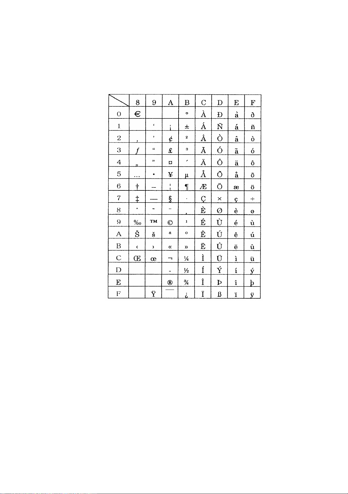
10.10 Windows Codepage
– 85 –
Page 100

10.11 Codepage PC858 (Multilingual+Euro)
– 86 –
 Loading...