

Page 1

SEISMIC VELOCITY TRANSDUCER T1-40
Measurement of Omnidirectional Absolute Vibrations
Certified according to ATEX 94/9/CE directive
OPERATION
Transducer T1-40 serves for seismic measurement of the absolute vibrations of the machinery through direct fixing
(omnidirectional) on the supports of the vibrating part in a dangerous area. It supplies an output signal directly
proportional to the vibration speed of the point to which it is fastened. Such signal is then processed in a safe zone by
a measuring channel of the “T” series.
The transducer, in its various models, is certified for applications in areas classified as:
ZONE 0 ZONE 1
- Ex II 1GD Ex ia IIC T6 Ex iaD 20 T85°C - Ex II 2GD Ex ia IIC T6 Ex iaD 21 T85°C
- Ex II 1GD Ex ia IIC T5 Ex iaD 20 T100°C - Ex II 2GD Ex ia IIC T5 Ex iaD 21 T100°C
- Ex II 1GD Ex ia IIC T4 Ex iaD 20 T135°C - Ex II 2GD Ex ia IIC T4 Ex iaD 21 T135°C
PRINCIPLE OF OPERATION
A voltage, proportional to the speed of vibration, is induced in a coil suspended seismically to the transducer body
and immersed in a field generated by a permanent magnet rigidly fastened to the transducer body.
Page 2

SPECIFICATIONS
Type of measurement : SEISMIC (absolute vibrations)
Field of application : AMPLITUDE = ± 1000 µm p.p.
FREQUENCY = 10÷1000 Hz
DIRECT. OF VIBR. = ANY
Rated sensitivity : 21,2 mV/mm/sec (RMS) a 25°C
Typical frequency : 12 Hz
Damping coeff. : 0.7
Cross sensitivity : < 7%
Output impedance : 1 Kohm at 25°C
Power supply : None
Ambient operating range : Temperature = see certification
Humidity = 100% max
Ambient = IP65 EN 60529/10.91
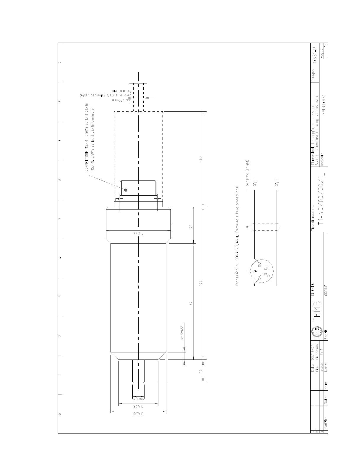
External connections : Connector MS/MIL-C-5015 series 3102/16, std. accessory
Outer casing material : Alluminium P.Al.Si 5.5 (Zone 1)
or
Stainless steel AISI 303 (Zone 0)
Weight of transducer : approx. 0.300 kg
Fastening : Screw, M8x1.25 – L=16 mm
Maintenance : None
Enclosed drawings : 17951 = Overall dimensions, layout and el. connections.
TRANSDUCER POSITIONING
Refer to drawing 17951.
N.B.: The operations should be performed possibly with the machine stationary and
taking the greatest care so as not to damage the internal mechanisms of the transducer.
1) On the support to be measured, drill a hole M8x1.25, 17 mm min. depth, making sure of its perpendicularity (if it is
not possible to reach the depth of 17 mm, provide spacers of suitable thickness between the support surface and
the transducer).
The surface on which the transducer rests should be flat and smooth. It is advisable to apply a layer of silicone
between the casing and the resting surface.
2) Screw the transducer in the M8x1.25 hole provided at point 1. Avoid knocks on the transducer. The use of a
thread compound is advisable during tightening.
3) Carry out the electrical connections of the transducer to the measuring instrument by using the free lead
connector (supplied as standard).
Notes regarding positioning:
- The wiring MUST be made with cables resistant to agents related to the workplace (oils, corrosive acids,
temperature, etc.).
- Shielded cables MUST be used. Make sure that the shield is connected to the frame earth (GND=ground) at just
one of the cable ends (the instrument side is advised).
- The electrical conductors must all have a minimum cross section of 1.0 mm², max. possible cross section = 2.5
mm² for a max. distance of approx. 800 metres.
T1-40-ATEX 04 gb 2
Page 3

Notes concerning certification:
1) The use of ATEX certified transducers is not allowed for different hazardous conditions or for those
exceeding the data specified on the nameplate affixed to the transducer.
2) The transducer does not require maintenance. Any work regarding performance checks or repair
should only be carried out in a laboratory duly authorized by CEMB SpA.
Notes for the identification :
The TRANSDUCER is manufactured in various versions in order to be correctly used according to :
1) the dangerous Zones where they will be used (zone 0 and 1)
2) the operating temperature (ambient t. and maximum t.)
3) the ambient operating characteristics (suitable or less suitable atmospheres for
the following materials : STAINLESS STEEL, ALUMINIUM, PLASTIC)
These characteristics must match in order to meet ALL the plant requirements. The CEMB codes with
which the main versions are identified and which meet requirements as per points 1 to 3 are as follows:
CEMB Code ZONE 0
9801145T4 TRANSDUCER T1-40/00/00/1C (-40÷+100°C) II 1GD Ex ia IIC T4 Ex iaD 20 T135°C
+135°C SURFACE, Zone 0, ATEX
9801145T5 TRANSDUCER T1-40/00/00/1B (-40÷+80°C) II 1GD Ex ia IIC T5 Ex iaD 20 T100°C
+100°C SURFACE, Zone 0, ATEX
9801145T6 TRANSDUCER T1-40/00/00/1A (-40÷+60°C) II 1GD Ex ia IIC T6 Ex iaD 20 T85°C
+85°C SURFACE, Zone 0, ATEX
CEMB Code ZONE 1
9831145T4 TRANSDUCER T1-40/00/00/1N (-40÷+100°C) II 2GD Ex ia IIC T4 Ex iaD 21 T135°C
+135°C SURFACE, Zone1,ATEX
9831145T5 TRANSDUCER T1-40/00/00/1M (-40÷+80°C) II 2GD Ex ia IIC T5 Ex iaD 21 T100°C
+100°C SURFACE, Zone1,ATEX
9831145T6 TRANSDUCER T1-40/00/00/1L (-40÷+60°C) II 2GD Ex ia IIC T6 Ex iaD 21 T85°C
+85°C SURFACE, Zone 1,ATEX
T1-40-ATEX 04 gb 3
Page 4
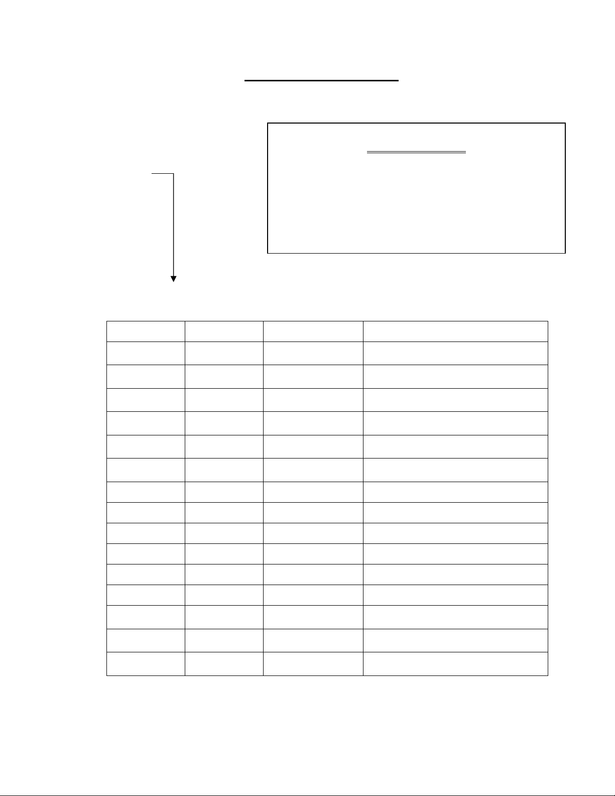
D
T1- 40 / 00 / 00 /
Where “D” =
D : Certification Code
“D” Code BODY CONNECTOR MARKING
/1A
/1B
/1C
/1D
/1E
/1F
/1G ALUMINIUM PLASTIC II 2GD Ex ia IIC T6 Ex iaD 21 T85°C
STAINLESS
STAINLESS
STAINLESS
STAINLESS
STAINLESS
STAINLESS
STEEL
STEEL
STEEL
STEEL
STEEL
STEEL
Information complete table
Example of order
T1-40/00/00/1A
1A = Certif. Atex II 1GD Ex ia IIC T6 Ex iaD 20 T85°C
FOR ZONE 0, WITH PLASTIC CONNECTOR AND
STAINLESS STEEL BODY
PLASTIC II 1GD Ex ia IIC T6 Ex iaD 20 T85°C
PLASTIC II 1GD Ex ia IIC T5 Ex iaD 20 T100°C
PLASTIC II 1GD Ex ia IIC T4 Ex iaD 20 T135°C
ALUMINIUM II 2GD Ex ia IIC T6 Ex iaD 21 T85°C
ALUMINIUM II 2GD Ex ia IIC T5 Ex iaD 21 T100°C
ALUMINIUM II 2GD Ex ia IIC T4 Ex iaD 21 T135°C
/1H ALUMINIUM PLASTIC II 2GD Ex ia IIC T5 Ex iaD 21 T100°C
/1I ALUMINIUM PLASTIC II 2GD Ex ia IIC T4 Ex iaD 21 T135°C
/1L ALUMINIUM ALUMINIUM II 2GD Ex ia IIC T6 Ex iaD 21 T85°C
/1M ALUMINIUM ALUMINIUM II 2GD Ex ia IIC T5 Ex iaD 21 T100°C
/1N ALUMINIUM ALUMINIUM II 2GD Ex ia IIC T4 Ex iaD 21 T135°C
/1P
/1Q
/1R
T1-40-ATEX 04 gb 4
STAINLESS
STEEL
STAINLESS
STEEL
STAINLESS
STEEL
PLASTIC II 2GD Ex ia IIC T6 Ex iaD 21 T85°C
PLASTIC II 2GD Ex ia IIC T5 Ex iaD 21 T100°C
PLASTIC II 2GD Ex ia IIC T4 Ex iaD 21 T135°C
Page 5
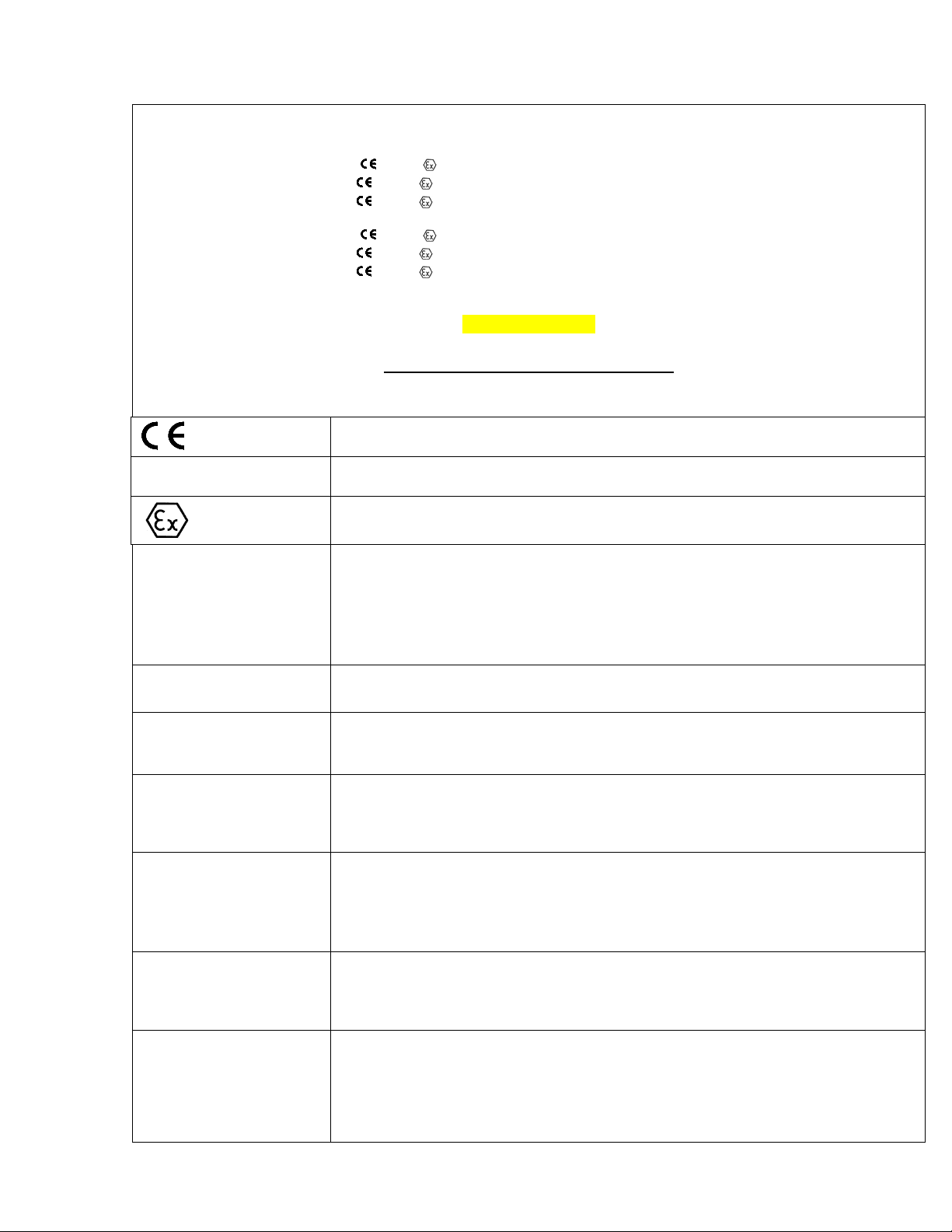
Certifications according to ATEX 94/9/CE
0722 II 1GD Ex ia IIC T6 Ex iaD 20 T85°C
0722 II 1GD Ex ia IIC T5 Ex iaD 20 T100°C
0722 II 1GD Ex ia IIC T4 Ex iaD 20 T135°C
0722 II 2GD Ex ia IIC T6 Ex iaD 21 T85°C
0722 II 2GD Ex ia IIC T5 Ex iaD 21 T100°C
0722 II 2GD Ex ia IIC T4 Ex iaD 21 T135°C
CESI 01 ATEX 050
Legend of nameplate safety data
Marking of compliance with the applicable European directives
0722
II 1GD / II 2GD
Ex ia
II C
T6-T5-T4
Ex iaD T85°C
Ex iaD T100°C
Ex iaD T135°C
Number of the Notified Body carrying out the surveillance (CESI)
Marking of compliance with 94/9/CE Directive and relevant technical
standards
II 1 GD Equipment intended for use in areas in which Ex atmosphere
caused by gases and dust, suitable for Zone 0 and 20
II 2 GD Equipment intended for use in areas in which Ex atmosphere
caused by gases and dust, suitable for Zone 1 and 21
Not suitable for mines
Equipment belonging to category "ia" with intrinsic safety
Suitable for substances (gas) of group IIC, also suitable for groups IIA
and IIB
T6 temperature class (surface temperature: 85°C)
T5 temperature class (surface temperature: 100°C)
T4 temperature class (surface temperature: 135°C)
Protection for Dust
For T6 class, ambient temperature : -40 ÷ 60 °C
T. amb.
For T5 class, ambient temperature : -40 ÷ 80 °C
For T4 class, ambient temperature: -40 ÷ 100 °C
Certificate identification :
• Name of the laboratory issuing the CE-type-examination certificate
CESI 01 ATEX 050
• 01 = year of certificate issue
• 050 = certificate number
T1-40-ATEX 04 gb 5
Page 6
ASTD90420
T1-40-ATEX 04 gb 6
 Loading...