

Page 1

Instructions for use
Contents Page
1 - GENERAL......................................................................................................................................................................3
1.1 - GENERAL SAFETY REGULATIONS ...............................................................................................................3
1.1.1 - STANDARD SAFETY DEVICES ..........................................................................................................3
1.2 - FIELD OF APPLICATION .................................................................................................................................3
1.3 - OVERALL DIMENSIONS .................................................................................................................................3
1.4- SPECIFICATION ..............................................................................................................................................4
2 - HANDLING, HOISTING ...............................................................................................................................................4
3 - START-UP ....................................................................................................................................................................5
3.1 - ANCHORING ....................................................................................................................................................5
3.2 - ELECTRICAL CONNECTION . ......................................................................................................................... 5
3.3 - PNEUMATIC CONNECTION (Versions SE ) .....................................................................................................5
3.4 - EXTRA SAFETY DEVICES (VERSION SE ).....................................................................................................5
3.5 - ADAPTER MOUNTING ....................................................................................................................................5
SE2 MOUNTING ........................................................................................................................................................6
SE2 DISMOUNTING ..................................................................................................................................................7
3.5 - WHEEL GUARD ASSEMBLY AND ADJUSTMENT............................................................................................8
3.7 - SPACER WD......................................................................................................................................................8
4 - CONTROLS AND COMPONENTS .............................................................................................................................8
4.1 - BRAKE PEDAL...................................................................................................................................................8
4.2 - PNEUMATIC LOCKING PEDAL (Version P)...................................................................................................... 8
4.3 - AUTOMATIC RIM DISTANCE AND DIAMETER GAUGE ................................................................................. 9
4.4 - AUTOMATIC WIDTH GAUGE (OPTIONAL) .....................................................................................................9
4.5 - AUTOMATIC WHEEL POSITIONING ................................................................................................................9
4.6 - CONTROL PANEL AND DISPLAY .................................................................................................................10
4.6.1 CONTROL OF THE FUNCTIONS MENU .............................................................................................11
5 - INDICATIONS AND USE OF THE WHEEL BALANCER .......................................................................................... 12
5.1 - DOUBLE OPERATOR PROGRAM .................................................................................................................12
5.2 - PRESETTING OF WHEEL DIMENSIONS ....................................................................................................12
5.2.1 - AUTOMATIC PRESETTING ............................................................................................................... 12
5.2.1.1 - “AUTOMATIC WIDTH” OPTION........................................................................................................ 13
5.2.1.2 - WHEEL ALU-S ..................................................................................................................................13
5.2.2 - MANUAL PRESETTTING .................................................................................................................. 14
5.3 - RECALCULATION OF THE UNBALANCE ....................................................................................................15
5.4 - RESULT OF MEASUREMENT ....................................................................................................................... 15
5.4.1 - INDICATION OF EXACT CORRECTION POSITION IN ALU-S ........................................................15
5.4.2 - RESOLUTION OF THE UNBALANCE (SPLIT) ..................................................................................16
5.4.3 - UNBALANCE OPTIMIZATION ...........................................................................................................18
5.4.4 - ALU AND STATIC MODES ................................................................................................................. 19
5.4.5 -AUTOMATIC MINIMIZATION OF STATIC UNBALANCE .....................................................................19
5.5 - ECCENTRICTY MEASUREMENT (OPTION).................................................................................................. 20
6 - SET UP ......................................................................................................................................................................21
6.1 - SELF-DIAGNOSTICS .....................................................................................................................................21
6.2 - SELF-CALIBRATION ......................................................................................................................................22
6.3 - SCREEN SAVER.............................................................................................................................................23
6.4 - TYPE OF DISPLAY OF UNBALANCE PHASE ................................................................................................ 24
6.5 - AUTOMATIC GAUGES .................................................................................................................................25
6.5.1 - RIM DISTANCE GAUGE ....................................................................................................................25
6.5.2 - DIAMETER GAUGE ...........................................................................................................................25
6.5.3 - WIDTH GAUGE (OPTIONAL)).............................................................................................................26
6.6 - AMBIENT TEMPERATURE.............................................................................................................................. 26
7 - ERRORS ....................................................................................................................................................................27
7.1 - INCONSISTENT UNBALANCE READINGS ..................................................................................................28
8 - ROUTINE MAINTENANCE ........................................................................................................................................28
8.1 - TO REPLACE THE FUSES..............................................................................................................................28
9 - RECOMMENDED SPARE PARTS LIST .....................................................................................................................29
I
I 0307_0308 - 1
GB
Page 2

I 0307_0308 - 2
GB
Page 3
1- GENERAL
1.1 - GENERAL SAFETY RECOMMENDATIONS
- The balancing machine should only be used by duly authorized and trained personnel.
- The balancing machine should not be used for purposes other than those described in the
instruction manual.
- Under no way should the balancing machine be modifi ed except for those modifi cations made
explicitly by the manufacturer.
- Never remove the safety devices. Any work on the machine should only be carried out by duly
authorized specialist personnel.
- Do not use strong jets of compressed air for cleaning.
- Use alcohol to clean plastic panels or shelves (AVOID LIQUIDS CONTAINING SOLVENTS).
- Before starting the wheel balancing cycle, make sure that the wheel is securely locked on the
adapter.
- The machine operator should not wear clothes with fl apping edges. Make sure that unauthorized
personnel do not approach the balancing machine during the work cycle.
- Avoid placing counterweights or other objects in the base which could impair the correct
operation of the balancing machine.
1.1.1 - STANDARD SAFETY DEVICES
- STOP push button for stopping the wheel under emergency conditions.
- The safety guard of high impact plastic is with shape and size designed to prevent risk of
counterweights from fl ying out in any direction except towards the fl oor.
- A microswitch prevents starting the machine if the guard is not lowered and stops the wheel
whenever the guard is raised.
1.2 - FIELD OF APPLICATION
The machine is designed for balancing car or motorcycle wheels weighing less than 65 kg. It can be
operated within a temperature range of 0° to + 45°C.
It can measure the geometric radial run-out of the wheels (optional)
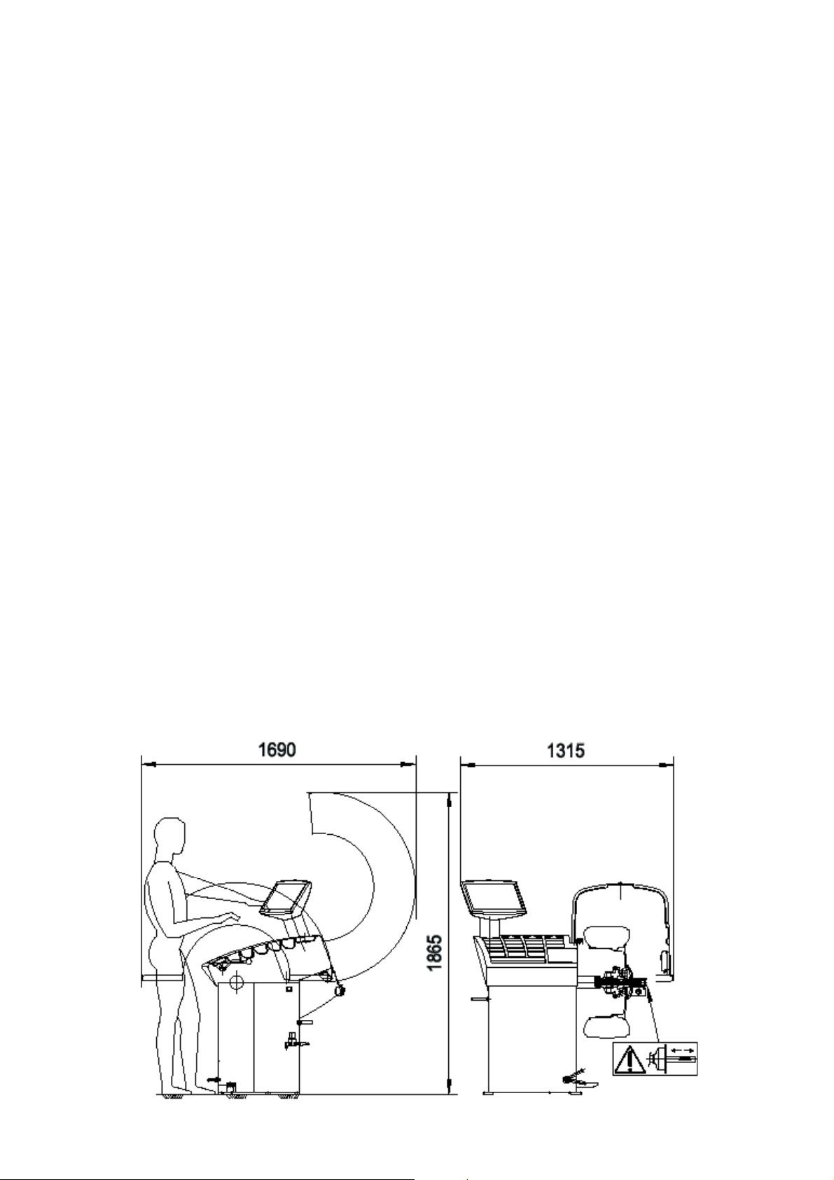
1.3 - OVERALL DIMENSIONS (42" Protection)
Fig. 1
I 0307_0308 - 3
GB
Page 4
1.4 - SPECIFICATION
Single phase power supply ............................... 115 - 230 V 50-60 Hz
Protection class ................................................ IP 54
Max. power consumption .................................. 1100 W
Balancing speed approx.................................... 180 min
Cycle time for average wheel (14 Kg) .............(14 Kg) 6 seconds
Balancing accuracy ...........................................0,1 grammi
Position resolution ............................................. ± 1.4 °
Average noise level ........................................... < 70 dB(A)
Distance rim - machine...................................... 0 - 280 mm (400 mm can be preset)
Rim width setting range .................................... 1.5” ÷ 20” or 40 ÷ 510 mm
Diameter setting range ...................................... 10” ÷ 26” or 265 ÷ 665 mm
Total wheel diameter within guard ..................... 1067 (42”)
Total wheel width within guard........................... 500 (42”)
Max. wheel weight............................................. 65 Kg.
Min/max. compressed air pressure ...................
.........................................................................................approx. 100 to 145 PSI.
7 ÷ 10 Kg/cm2 approx. 0.7 to 1 Mpa; approx. 7 to 10 BAR;
-1
Fig. 2
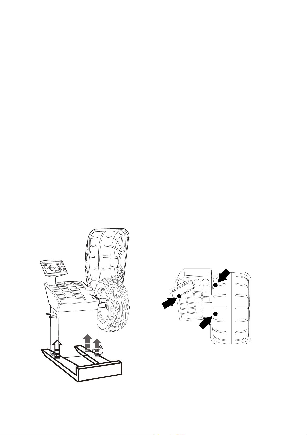
2 - HANDLING AND HOISTING
Fig. 2a
I 0307_0308 - 4
GB
NB: DO NOT HOIST THE MACHINE USING DIFFERENT GRIPS
Page 5
3 - COMMISSIONING
3.1 - ANCHORING
The machine can be operated on any fl at non-resilient fl oor.
Make sure that the machine rests solely on the three support points provided (fi g. 2a).
It is advisable to secure the system to the ground using the specifi c feet (see Figure 2a) in the
event of continual use with wheels weighing over 35 Kg.
3.2 - ELECTRICAL CONNECTION
The machine is supplied with a single phase mains cable plus earth (ground).
The supply voltage (and mains frequency) is given on the machine nameplate. It may NOT be changed.
Connection to the mains should always be made by expert personnel.
The machine should not be started up without proper earth (ground) connection.
Connection to the mains should be through a slow acting safety switch rated at 4A (230V) or 10A (115V) .
3.3 - PNEUMATIC CONNECTION (Versions SE)
For operation of the spindle with pneumatic locking (costant thrust air spring) connect the balancing to the
compressed air main. The connection fi tting is located at the back of the machine. At least 7 Kg/cm2 (~ 0.7
MPa; ~ 7 BAR; ~ 100 PSI) pressure is needed for correct operation of the release device.
3.4 - EXTRA SAFETY DEVICES (VERSION SE)
- Wheel always locked even when there is pressure failure during the balancing cycle.
- Always actuate the unlocking control pedal with the machine stationary in order to avoid stress
and abnormal wear on the adapter.
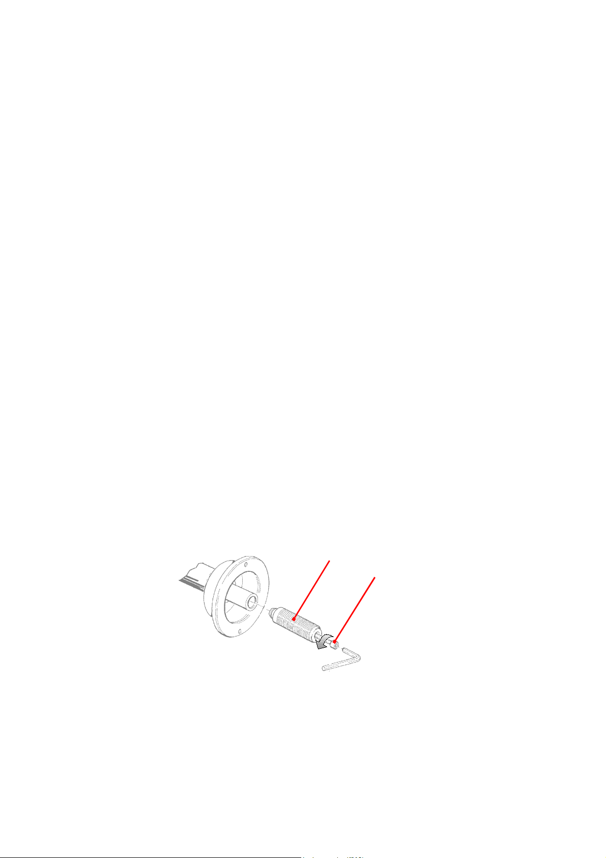
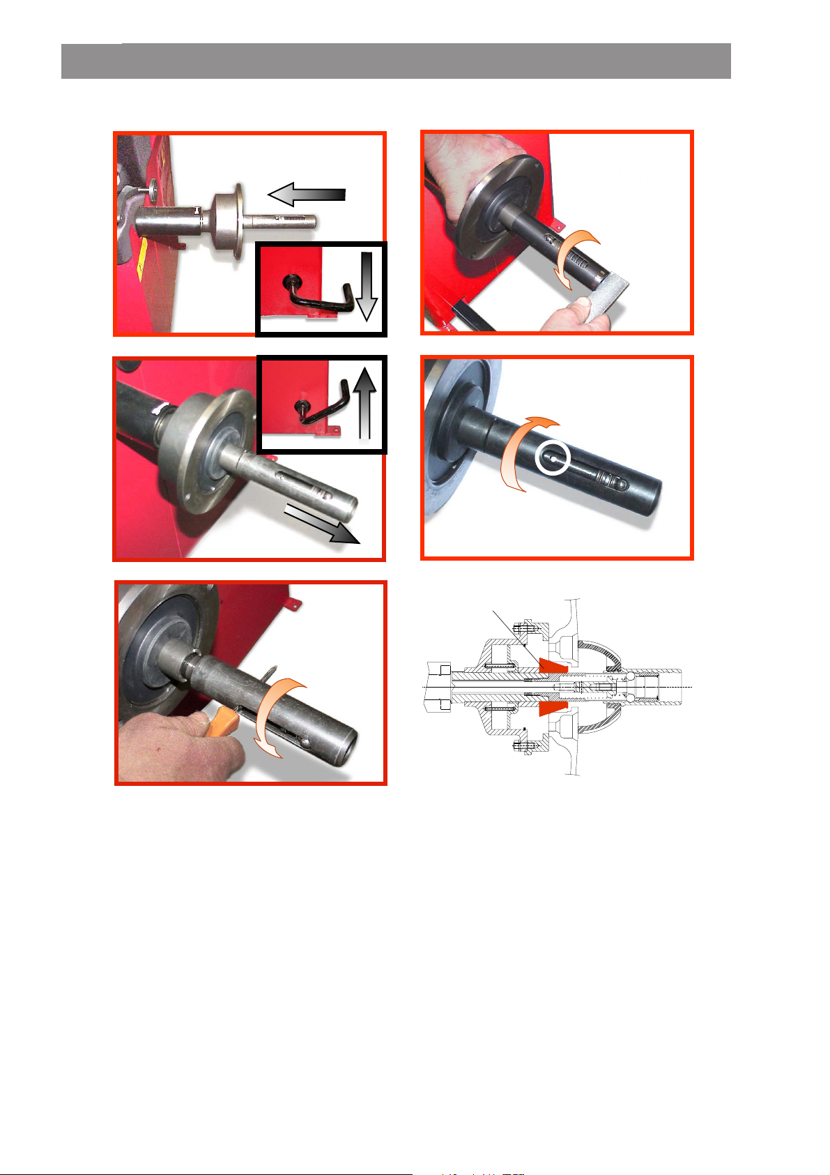
3.5 - ADAPTER MOUNTING
The balancing machine is supplied complete with cone adapter for fastening wheels with central bore.
Other optional fl anges can be mounted once the terminal part is removed (also see enclosed brochures)
N.B. Carefully clean the coupling surfaces before performing any operation
a) DISMOUNTING THREADED END PIECE
A
Fig. 3
B
a) Back-off screw B and remove threaded end-piece A.
b) Fit the new adapter
I 0307_0308 - 5
GB
Page 6
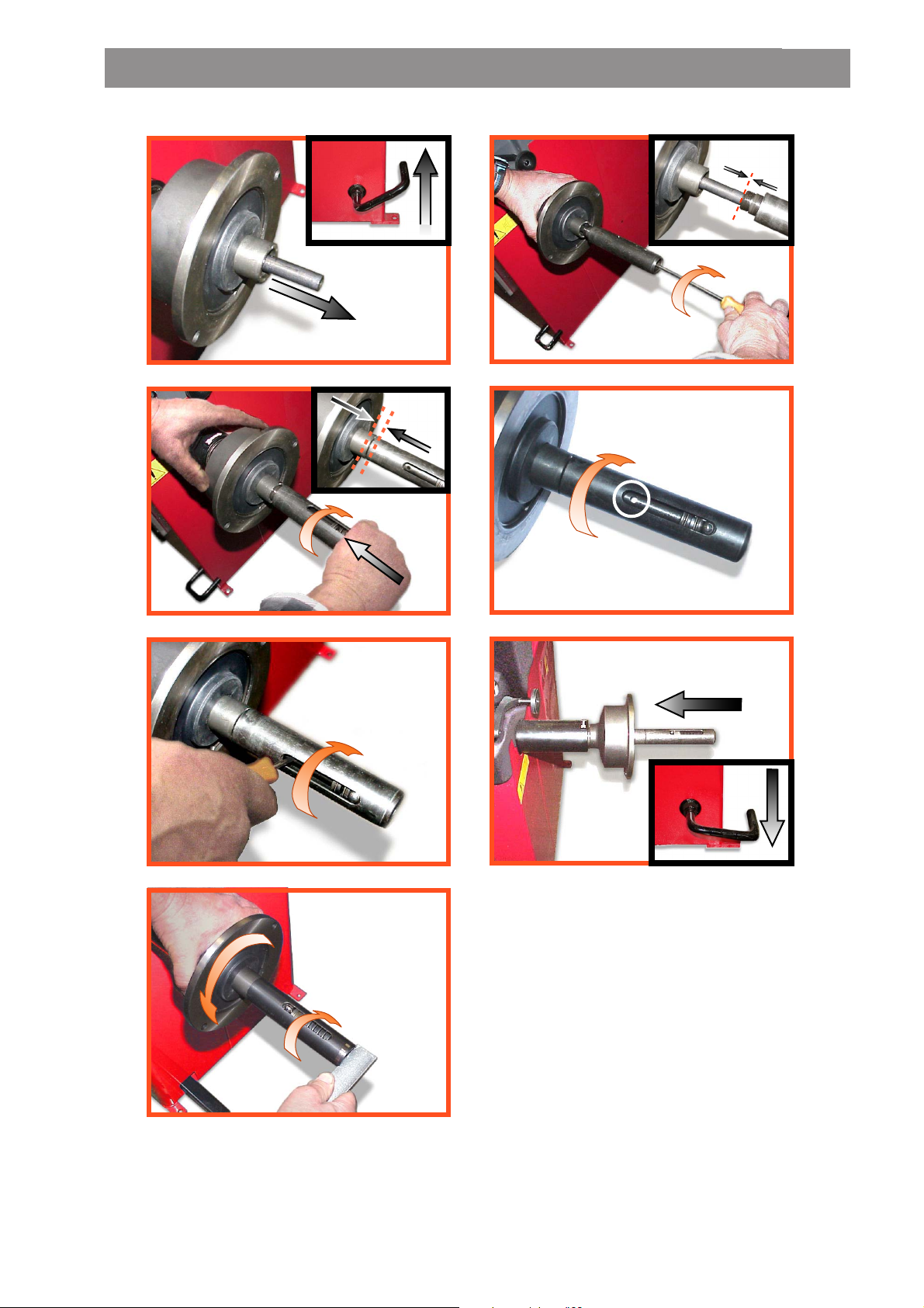
SE2-Mounting
0 mm
a
1-2 mm
c
b
d
e
g
f
SE2_ 0140
Page 7
SE2-Dismounting
360°
a
c
b
d
Cone
e
- Quando possibile, centrare le ruote con cono dall'interno (vedi disegno).
- Evitare di usare il manicotto RL con cerchi di ferro.
- Whenever possible, centre the wheels with the cone from the inside (see the drawing).
- Avoid using the RL sleeve with metal rims.
- Lorsque c’est possible, centrer les roues avec le cône de l’intérieur (voir dessin).
- Eviter d’utiliser le manchon RL avec les jantes en fer.
- Wenn möglich, die Räder mit Konus von Innen heraus zentrieren (siehe Zeichnung).
- Bei Eisenfelgen die Verwendung der Muffe RL vermeiden.
- Siempre que sea posible, centrar las ruedas con cono desde dentro (véase dibujo).
- Evitar usar el manguito RL con llantas de hierro.
SE2_ 0140
Page 8
3.6 - GUARD MOUNTING AND ADJUSTMENT
a) Fasten the components to the base as illustrated in specifi c exploded view.
b) The position of the wheel guard when closed can be adjusted with relative screw accessible at the back.
Correct position is the one which keeps the tube exactly horizontal with wheel guard closed.
c) Check that the microswitch is held down when the guard is closed.
d) Adjust the angular position of microswitch control.
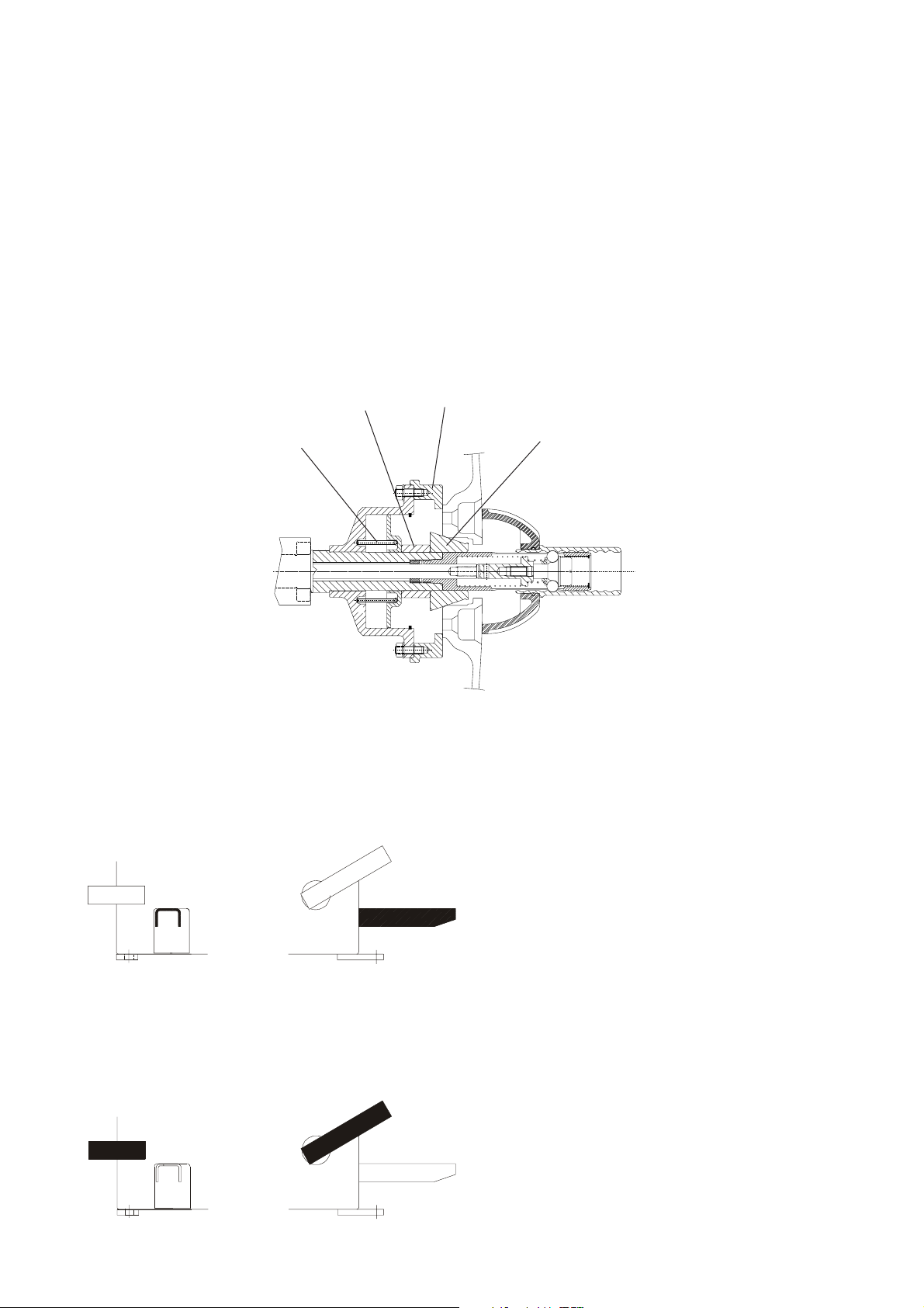
3.7 - SPACER WD
When balancing very wide wheels (9”), there is not enough space to turn the distance gauge. To withdraw
the wheel from the machine side, fi t spacer WD on the adapter body and secure it with the standard issue
nuts. When centring the wheel with the cone on the inside, fi t the spacer DC to obtain spring thrust.
Fig.4
4 - CONTROLS AND COMPONENTS
4.1 - BRAKE PEDAL
Fig.5
Spring
DC
WD
Cone
This pedal allows the operator to hold the
wheel when fi tting the counterweights.
It must not be actuated during the
measuring cycle.
4.2 - PNEUMATIC LOCKING PEDAL (Version P)
Fig.6
I 0307_0308 - 8
GB
This pedal allows releasing the device
fastening the wheel on the adapter.
Do not actuate this pedal during the
machine cycle and/or when adapters
other than the standard cone
adapter are mounted.
The pedal has two stable positions:
top, wheel unclamped; bottom,
wheel clamped
Page 9

4.3 - AUTOMATIC DISTANCE AND DIAMETER GAUGE
This gauge allows measurement of the distance of the wheel from the machine and the wheel diameter at
the point of application of the counterweight.
It also allows correct positioning of the counterweights on the inside by using the specifi c function which
allows reading the position used for the measurement within the rim.
The gauge can only be used with the counterweight pincers mounted.
4.4 - AUTOMATIC WIDTH GAUGE (OPTIONAL)
Width gauging is through a SONAR device which measures the distance of the wheel without mechanical
contact, merely by closing the guard and each time a valid measurement has been made with gauge
DISTANCE AND DIAMETER GAUGE.
4.5 - AUTOMATIC WHEEL POSITIONING
At the end of the spin, the wheel is positioned according to the unbalance on the outside or else
according to the static unbalance (when selected).
Precision is ± 20° for wheels up to 25 kg. in weight. Positioning is automatically disenabled for wheels
of less than 13” in diameter.
I 0307_0308 - 9
GB
Page 10

CONTROL PANEL AND DISPLAY
Fig. 7
5
7
3
8
1
1-2 Digital readouts, AMOUNT OF UNBALANCE, inside/outside
3-4 Digital readouts, POSITION OF UNBALANCE, inside/outside
5 Indicators, correction mode selected
6 User Indicators
7 Weight correction position indicators
8 Distance gauge position indicator
9 SPLIT “ON” indicator
10 OPT “ON” indicator
11 Measurements in mm indicator
12 ALUS “ON” indicator
13 Push button, operator selection
14 Push button, SPLIT (unbalance resolution)
15 Emergency push button
16 Push button, cycle start
17 OPT Pushbutton (unbalance optimisation)
18 HOME Pushbutton (terminate function)
19 Push button, FUNCTIONS MENU
20 Inch/mm dimensions selection pushbutton
21 Push button, eccentricity measurement selection (optional)
22 Push button, menu selection confi rmation
23 Push button, selection of mode of correction
24 Position repeater push button
25 Push button, unbalance reading < 5 g (25 oz)
26 Push buttons, manual DISTANCE/DIAMETER/WIDTH setting
4
2
6
10
11
12
13
14
9
18
17
20
23
26
15
16
19
21
22
24
25
Note: - Only use the fi ngers to press the push buttons. Never use the counterweight pincers or other
pointed objects.
- In case of audible alarm connected (see par.
push button operation sounds with a “beep” alarm.
I 0307_0308 - 10
GB
OPERATION FUNCTIONS MENU), any
Page 11

OPERATION FUNCTIONS MENU
Eccentricity
measurement
on/off (option)
CONFIRM
guard on/off
on/off start from
guard closing
approximates
1-5g or .1-.25 oz
on/off beep
signal
See SELF-DIAGNOSTICS chapter
See SELF-CALIBRATION chapter
measurement
Screen-saver
g/oz
unit of
unbal.
duration
(in minutes)
Type of
display of
unbalance
phase
Calibration of automatic RIM DISTANCE gauge
CONFIRM
CONFIRM
CONFIRM
CONFIRM
CONFIRM
CONFIRM
CONFIRM
Calibration of automatic DIAMETER gauge
Calibration of automatic WIDTH gauge (optional)
RETURNS TO MEASUREMENT SCREEN
N.B. If such indications fail to appear, contact Technical Service
*
Ambient
temperature
(in °C)
CONFIRM
I 0307_0308 - 11
GB
Page 12
5 - INDICATIONS AND USE OF THE WHEEL BALANCER
5.1 - DOUBLE OPERATOR PROGRAM
This program allows memorizing the dimensions of two types of wheels. Thus two operators can work
simultaneously on two different cars using the same balancing machine. The system memorizes two
programs with various preset dimensions.
1 - Press
2 - Enter the dimensions (see PRESETTING OF WHEEL DIMENSIONS)
3 -
With program 1 or 2 is called for subsequent balancing operations without having to newly enter
the dimensions.
to select operator (1 or 2). Selection is confi rmed by panel-mounted LED.
carry out the balancing as usual
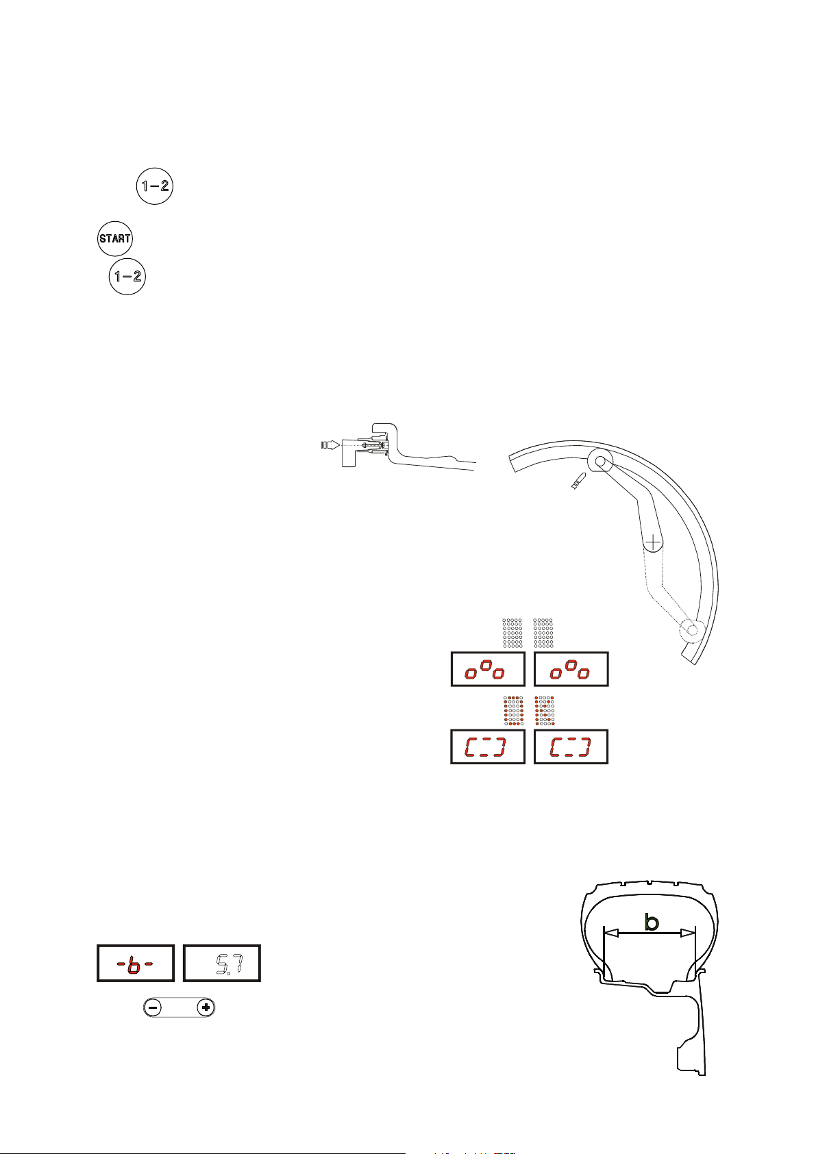
5.2 - PRESETTING OF WHEEL DIMENSIONS
5.2.1 - AUTOMATIC PRESETTING
- Standard wheels (calibration necessary also for modes ALU 1, 2, 3, 4 Static)
Fig. 8 DISTANCE + DIAMETER
Pos. A
Move the gauge tip into contact against the rim keeping it in
position for at least 2 seconds.
N.B. Measurement is the same in position A or B. Always use
the round part of the contact tip.
Indication of gauge in movement
Indication of dimensions acquired.
N.B.: When the beep signal is enabled (see section
OF THE FUNCTIONS MENU), reaching of the dimensions is
accompanied by a “beep”
Return the gauge to position 0. If automatic WIDTH readout is
disenabled (see
WIDTH position.
The system automatically switches to WIDTH position
GAUGE ENABLE), the system automatically goes to the
- The nominal width is normally stamped
on the rim; if not, proceed to measure
dimension “b” with the calibre gauge
(supplied as standard).
CONTROL
Pos. B
I 0307_0308 - 12
GB
Page 13

5.2.1.1 - “AUTOMATIC WIDTH” OPTION
If WIDTH measurement with sonar is enabled, the machine is set for the acquisition of this value:
Fig. 9
The LT script on the LH matrix display indicates that LIGHT TRUCK wheel measurement is set (large
dimension wheels such as off-road, trucks or wheels which protrude signifi cantly from the rim).
This function can be enabled/disenabled by pressing push button
is then performed by closing the guard; once completely closed and if “automatic START on guard closure”
is enabled, the launch will be made for unbalance measurement. If automatic START is disenabled, once
the guard is closed the display will show the width value measured.
5.2.1.2 - WHEEL ALU-S
(correction from inside for two balancing planes with direct calibration):
Fig. 10
prior to the measurement, which
After measurement for inside F1 as shown, again remove the gauge in order to memorize the data for the
outside FE; keep the position for at least 2 seconds. The measurement can be made either in the position
shown in Fig. 8/Pos.A or in Fig. 8/Pos.B.
Manual presetting is possible by using the push buttons as for detailed hereunder.
I 0307_0308 - 13
GB
Page 14

5.2.2 - MANUAL PRESETTING
- Standard wheels
Fig. 11
b
a
d
- Press
- Preset distance “a” of the inside of the wheel from the machine (in mm).
- Press to select -d-
- Preset the nominal diameter “d” indicated on the tyre.
- Press to select -b-
- Preset the nominal width which is normally stamped on the rim; if not,
measure dimension “b” with the calibre gauge (supplied as standard).
- Wheel ALU-S
- Measure the dimensions as shown in the
following diagram.
Fig. 12
to read -a- on the display
d
I
a
a
I
d
E
PRESETTING:
Press
N.B.: If dE is not preset, default value dE = 0.8 dl
During setting-up of values -b- -d- -dI- -dE- press button
(on machine start-up, the dimensions are in INCHES).
I 0307_0308 - 14
to select the measurement to set
GB
a
E
to switch measurement from inches to mm
Page 15

5.3 - RECALCULATION OF THE UNBALANCE
Press after new setting of the measurement
5.4 - RESULT OF MEASUREMENT
Fig. 13
Inside correction Outside correction
After performing a balancing spin, the amounts of unbalance are shown on the digital readouts.
When the matrix display is ON, this indicates the correct angular wheel position for fi tting
counterweights. (12 o’clock position). When the beep signal is enabled (see section
OF THE FUNCTIONS MENU), this is activated when the wheel reaches the correction position.
If the unbalance is less than the threshold selected, is displayed instead of the unbalance, with it
is possible to read the values below the threshold chosen gram by gram.
If the static unbalance is greater than 30 gr., the OPT Led fl ashes to suggest an unbalance optimisation
operation. (see UNBALANCE OPTIMIZATION)
CONTROL
5.4.1 - INDICATION OF EXACT CORRECTION POSITION IN ALU-S
In correction mode ALU-S it is possible to cancel approximations in the mounting of
the counterweights by proceeding as follows:
- press
- Insert the correct weight on the relative seat on the weight holder pincers
- Remove the gauge when the display shows:
to indicate that the gauge should be pulled further out
to indicate that the gauge should be returned to rest position
The left display gives the indications for reaching the position regarding the inside, while the right display
that of the outside
The position of the gauge is also indicated by the position repeater Led (8).
Position
reached on
the internal
side
Fig. 14
I 0307_0308 - 15
GB
Page 16

Fig. 15
Position
reached
on the
external side
- Bring the wheel into correct angular position.
- Move the gauge until the display corresponding to the selected correction plane shows the unbalance
value again.
- Rotate the rim until the correct weight lies against the rim.
- The fact that the weight application position is no longer vertical (fi g. 16) is offset automatically.
N.B. : It is not possible to put automatically the correction weight in the Fig.8/Pos.B position; always
rotate the rim in Fig.5/Pos.A
Fig. 16
5.4.2 - RESOLUTION OF THE UNBALANCE (SPLIT)
SPLIT only has meaning in the case of static unbalance or ALU-S on outside. It serves for hiding any
stick-on unbalance correction weights behind the rim spokes.
PRESETTING:
Perform a balancing spin (
I 0307_0308 - 16
GB
)
Fig. 17
- Place any spoke in the 12 o’clock position
-
- / confi rm the settings enabling unbalance
split
set the number of spokes
Page 17
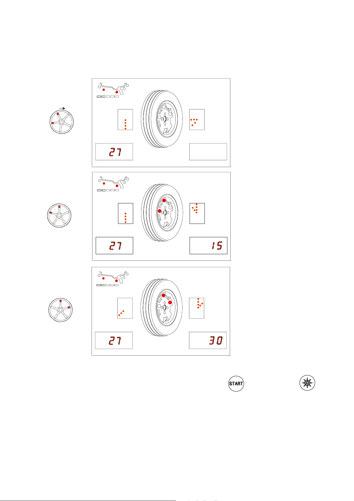
RESULTS UNBALANCE MEASUREMENT
Fig. 18
15
30
15
30
Unbalance breakdown NOT
in position
Correction position 1
30
15
To return to normal unbalance display, perform a new spin by pressing
Correction position 2
or else push button .
I 0307_0308 - 17
GB
Page 18

5.4.3 - UNBALANCE OPTIMIZATION
- This function serves to reduce the amount of weight to be added in order to balance the wheel.
- It is suitable for static unbalance exceeding 30 g.
- It improves the residual eccentricity of the tyre.
Unbalance already measured
No previous unbalance
measurement
unbalance measurement
TYRE
POSITION
- Mark with chalk a reference point on the
adapter and rim.
- With the aid of a tyre remover, turn the tyre on
the rim by 180°.
- Refi t the wheel with the reference mark
coinciding between rim and adapter.
- RH display: percentage reduction
- LH display: actual static unbalance which can
be reduced by rotation.
I 0307_0308 - 18
GB
RIM
POSITION
- Mark the two positions of the rim and tyre,
and turn the tyre on the rim until the positions
correspond in order to obtain the optimization
on the display.
RETURN TO MEASUREMENT SCREEN
Page 19

5.4.4 - ALU AND STATIC MODES
From the Measurement screen, press button to select the type required. The 5-LED displays show
the position where to apply the weights. If a spin has already been performed, the processor automatically
recalculates, for each change of mode, the amounts of unbalance according to the new calculation.
Fig. 19
DYNAMIC Balancing steel or light alloy wheel rims by
applying clamp weights on the edge of the wheel rim.
STATICO The static mode is necessary for motorcycle wheels or
when it is not possible to place the counterweights on
both sides of the rim.
ALU - S Balancing of light alloy rims with application of adhesive
weights in positions inside the rim (user settable).
ALU - 1 Balancing of light alloy rims with application of adhesive
weights on the rim shoulders.
ALU - 2 Balancing of light alloy rims with hidden application of
the outer adhesive weight. Outer weight position is fi xed.
12/13 mm
resting surface
ALU - 3 Combined application: clip-on weight inside and hidden
adhesive weight on outside (Mercedes). Outer weight
position is the same as ALU-2.
ALU - 4 Combined application: adhesive weight outside and
clip-on weight inside.
5.4.5 - AUTOMATIC MINIMIZATION OF STATIC UNBALANCE
Initial unbalance
sx
phase shift
Possible approximations
sx
residual static
With conventional
wheel balancer
dx
g g
4 g
sx
g g
residual static
dx
3 g
This program is designed to improve the quality of balancing without any mental effort or loss of time by the operator. In fact by using the normal commercially available weights, with pitch of 5 in every 5 g, and by applying the
two counterweights which a conventional wheel balancer rounds to the nearest value, there could be a residual
static unbalance of up to 4 g. The damage of such approximation is emphasized by the fact that static unbalance is
cause of most of disturbances on the vehicle. This new function, resident in the machine, automatically indicates the
optimum entity of the weights to be applied by approximating them in an “intelligent” way according to their position
in order to minimize residual static unbalance.
dx
g g
50
sx
residual static
Choice with minimum
static residual
dx
g g
1 g 6 g
sx
g g
residual static
dx
I 0307_0308 - 19
GB
Page 20

5.5 ECCENTRICTY MEASUREMENT (OPTION)
The fi gures are signifi cantly enlarged to highlight the external surface of the tyre and the wheel rotation axis.
Fig. A highlights the total Peak-Peak eccentricity measurement, defi ned as the maximum radial offset
of the surface of the tyre.
Fig. A Fig. B
Fig. B highlights the 1st harmonic eccentricity
measurement, i.e. the eccentricity of the rim
“refl ecting” the shape of the tyre, to calculate
the averages values of local offset of the tyre
from roundness.
It is evident that the P-P measurement is
normally higher than the 1st harmonic
measurement. Tyre manufacturers usually
provide two different tolerances for the two
types of eccentricity.
At the end of a balancing spin, eccentricity measurement of the tyre can be performed automatically
using the SONAR sensor placed on the guard. To enable measurement at the end of every spin, see
the section
Fig.20
MENU FUNCTION CONTROL.
EMS
EMS
The value of the fi rst harmonic with the relative phase
is displayed.
Hold down the
button to display the Peak-Peak
value.
Release the
button to return to the display of the
fi rst harmonic value.
BACK TO MEASUREMENT WINDOW
N.B.: The eccentricity measurement is valid up to max. tyre Ø of 1000 mm.
I 0307_0308 - 20
GB
Page 21

6.1 - SELF-DIAGNOSTICS
All displays, readouts and LED’s should light up
6 - SET UP
DISPLAY TEST
1
The RH display indicates the
current position of the wheel, with
numbers from 0 to 127
When the wheel is turned in the
unbalance measurement rotation
direction, the down arrows must
appear.
The central LED for the wheel (1)
must come on ONLY ONCE per
rotation at position 0.
- Test parameter
- Displays values of rim DISTANCE
sensor
- Displays values of DIAMETER
sensor
- Displys values of WIDTH sensor
(optional)
- Displays eccentricity measurement
sensor values (RUN OUT - option)
END OF SELF-DIAGNOSTICS
CANCELS SELF-DIAGNOSTICS
IN ANY PHASE
I 0307_0308 - 21
GB
Page 22
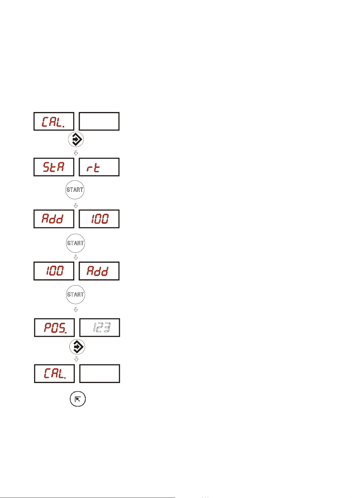
6.2 - SELF-CALIBRATION
For machine self-calibration proceed as follows:
- Fit a medium-sized metal wheel on the shaft. Example: 6” x 14” (± 1”)
- Preset the exact dimensions of the wheel mounted.
CAUTION!! Presetting of incorrect dimensions would mean that the machine is not correctly
calibrated, therefore all subsequent measurements will be incorrect until a new self calibration is performed with the correct dimensions!
- Perform a spin under normal conditions.
- Add 100 g (3.5 oz) on the outside in any angular position.
- Shift the 100 g. weight from the outside to the inside keeping
the same angular position.
- Shift the 100 g. weight to the 12 o’clock position.
END OF SELF-CALIBRATION
I 0307_0308 - 22
GB
CANCELS SELF-CALIBRATION IN ANY PHASE
Page 23

6.3 SCREEN SAVER
It is possible to enable a screen saver function which temporarily replaces the data displayed with moving
symbols. This function acts when the balancing system is not used for the time period defi ned in the
relative set-up:
Modify time expressed in minutes.
CONFIRM
If the value is set to 0, the screen saver is automatically disenabled.
The screen saver is not active in the balancing machine set-up menu.
To return to normal balancing machine function, simply press any button or move the wheel or the
distance gauge.
I 0307_0308 - 23
GB
Page 24

6.4 - TYPE OF DISPLAY OF UNBALANCE PHASE
The type of display of the unbalance phase can be selected, different from what is described in the
manual to date.
Changing the type of display of the unbalance phase.
CONFIRMATION
In this case the unbalance phase is indicated in the following way:
MEASURING RESULT
Inside correction Outside correction
- MEASURING RESULT OF SPLIT UNBALANCE:
Each weight to be applied has its own display (1 for the inside and 2 for the outside in ALU S).
Unbalance inconsistent NOT in position
Correction position 1
Correction position 2
N.B. The standard type of display is type 1, i.e. that
described throughout the manual.
I 0307_0308 - 24
GB
Page 25

6.5 - AUTOMATIC GAUGES
6.5.1 - RIM DISTANCE GAUGE
- Shift the distance gauge to position , keeping it quite still,
press
- Move the gauge to position , press
CORRECT CALIBRATION
- Return the gauge to rest position
- The wheel balancer is ready for operation
N.B.: In the event of errors or faulty operation, the writing
the gauge to position
error persists, contact the Technical Service Department. In the event of incorrect input in the rim
distance gauge calibration function, press
and repeat the calibration operation exactly as described above. If the
appears on the display : shift
to cancel it.
6.5.2 - DIAMETER GAUGE
- Currently preset diameter.
- Set the diameter with which to calibrate the machine (10÷18”)
with
- Press
- Move the gauge tip into measuring position (Fig. 8/Pos.A) and
keeping it still, press
CORRECT CALIBRATION
- Return the gauge to rest position
- The wheel balancer is ready for operation
In the event of incorrect input in the rim distance gauge calibration function, press
to cancel it.
I 0307_0308 - 25
GB
Page 26

6.5.3 - WIDTH GAUGE (OPTIONAL)
Set with the distance in mm between the
SONAR sensor and the distance gauge clamp in pos. 0.-
0
In the event of incorrect input in the width gauge calibration function, press
.
6.6 AMBIENT TEMPERATURE
When automatic width measurement or eccentricity measurement are enabled, the ambient temperature
must be set to ensure correct calibration of the sonar sensors.
Set the average ambient temperature for the
location of the balancing machine.
CONFIRM
I 0307_0308 - 26
GB
Page 27

7 - ERRORS
During machine operation, various causes of faulty operation could occur. If detected by the
microprocessor, they appear on the display as follows:
ERRORS CAUSES CONTROLS
Err. 1 No rotation signal. 1. Verify belt tautness.
Err. 2 Speed too low during detection.
Err. 3 Unbalance too high. 1. Verify wheel dimension settings.
Err. 4 Rotation in opposite direction.
Err. 5 Guard open
Err. 7 /
Err. 8
Err. 9 NOVRAM parameter write error. Replace the computer board.
Err. 10 Measured width too small.
Err. 11 Speed too high error.
Err. 12 Unbalance measuring cycle error. 1. Verify phase pick-up board function.
Err.13/
Err.14/
Err.15/
Err.16/
Err.17/
Err.18
During unbalance measurement rotation, wheel speed
is less than 42 rpm.
After pressing [START], the wheel begins to rotate in
the opposite direction (anticlockwise).
The [START] pushbutton was pressed without fi rst
closing the guard.
NOVRAM parameter read error 1. Repeat machine calibration
N.B.: Minimum width accepted by the
wheel balancer is 1.5” or 40 mm.
During unbalance measurement rotation, wheel speed
is more than 270 rpm.
Unbalance measurement error. 1. Verify phase pick-up board function.
2. Verify the function of the phase pick-up board and, in particular,
the reset signal.
3. Replace the phase pick-up board.
4. Replace the computer board.
1. Make sure that a vehicle wheel is mounted on the wheel balancer.
2. Verify belt tautness.
3. Verify the function of the phase pick-up board and, in particular,
the reset signal.
4. Replace the computer board.
2. Check detection unit connections.
3. Perform machine calibration.
4. Mount a wheel with more or less known unbalance (less than 100
grammes) and verify the response of the machine.
5. Replace the computer board.
1. Verify the connection of the UP/DOWN – RESET signals on the
phase pick-up board.
1. Reset the error by pressing pushbutton [7]=End.
2. Close the guard.
3. Verify the function of the protection uSwitch.
4. Press the [START] pushbutton.
2. Shut down the machine.
3. Wait for a minimum time of ~ 1 Min.
4. Re-start the machine and verify correct operation.
5. Replace the computer board.
1. Repeat the distance measurement.
2. Repeat the width measurement.
3. Verify the calibration of the distance gauge and replace the
distance gauge potentiometer as necessary.
4. Verify the calibration of the width gauge and replace the width
gauge potentiometer as necessary.
5. Replace the computer board.
1. Check if there is any damage or dirt on the timing disc.
2. Verify the function of the phase pick-up board and, in particular,
the reset signal.
3. Replace the computer board.
2. Verify correct motor operation.
3. Verify belt tautness.
4. Replace the computer board.
2. Check detection unit connections.
3. Verify machine earth/ground connection.
4. Mount a wheel with more or less known unbalance (less than 100
grammes) and verify the response of the machine.
5. Replace the computer board.
I 0307_0308 - 27
GB
Page 28

7.1 - INCONSISTENT UNBALANCE READINGS
Sometimes after balancing a wheel and removing it from the balancing machine, it is found that, upon
mounting it on the machine again, the wheel is not balanced.
This does not depend on incorrect indication of the machine, but only on faulty mounting of the wheel
on the adapter; i.e. in the two mountings, the wheel has assumed a different position with respect to the
balancing machine shaft centre line. If the wheel has been mounted on the adapter with screws, it could
be possible that the screws have not been correctly tightened, i.e. crosswise one by one, or else (as often
occurs) holes have been drilled on the wheel with too wide tolerances.
Small errors, up to 10 grams (0.4 oz) are to be considered normal in wheels locked by a cone; the error is
normally greater for wheels fastened with screws or studs.
If, after balancing, the wheel is found to be still out-of-balance when refi tted on the vehicle, this could be
due to the unbalance of the car brake drum or very often due to the holes for the screws on the rim and
drum sometimes drilled with too wide tolerances. In such case a readjustment could be advisable using
the balancing machine with the wheel mounted (For example, see our models L36, L38/2).
8 - ROUTINE MAINTENANCE
Switch off the machine from the mains before carrying out any operation.
8.1 - TO REPLACE THE FUSES
The power supply board, accessible from the rear by removing the rear cover, is fi tted with safety fuses
(see Exploded Drawings). If fuses require replacement, use ones of the same current rating.
If the fault persists, contact the Technical Service Department.
NONE OF THE OTHER MACHINE PARTS REQUIRE MAINTENANCE.
I 0307_0308 - 28
GB
Page 29

9 - RECOMMENDED SPARE PARTS LIST
(For further details, see exploded drawings)
CODE DESCRIPTION
020600503 Bearing 6005-2Z dia. 25/47/12
181198630 Spring 19863P
080077007 Rigid belt Poly V - TB2 - 770 - 7 Vee’s
67M38954C Position pick-up board with cable
182245870 Spring, brake lever 24587P
05PR50728 LEXAN panel
182185750 Spring, rim distance gauge
67M48208A Power board with 2 relays/ 2 sonar
681002000 Fuses DM 5x20 - 2A
511242101 Oscillating switch 16A
86SC50842 Computer board
86SB38988 Cable, automatic rim distance gauge
86SB36493 Cable, automatic diameter gauge
86SB50843 Width sonar (optional)
86SB38585 Cable with microswitch for 42” protection
SPECIAL PARTS FOR 230V MACHINES
50FG55641 Single phase motor 230V/50-60 Hz -0.18Kw 63/B3 - 4p HB63D-4
86SZ50844 Complete power board
611000314 Braking transformer 30VA 230 - 0/50
568001458 Capacitor 14MF 450 V FASTON screw M8
611051827 Power transformer 40VA
SPECIAL PARTS FOR 115V MACHINES
50FG55643 Single phase motor 115V/50-60Hz- 0.18Kw - 63/ B3 - 4p HB63D-4
86SZ50845 Complete power board
611000313 Braking transformer 30VA 115-0/25
568002557 Capacitor 25MF 450V FASTON screw M8
611051828 Power transformer 40VA
SPECIAL PARTS FOR SPINDLE SE
020600702 Bearing 6007 - LLB/2AV1 dia. 35/62x14 Front.
020600703 Bearing 6007 - 2Z dia. 35/62x14 Rear.
18FP29329 Air spring 115 kg. stroke 75 mm.
16FB42177 Coil valve
18FB42639 Spring, pneumatic pedal
SPECIAL PARTS FOR EMS SONAR (OPTION)
86SB50847 Ems sonar
I 0307_0308 - 29
GB
Page 30

I 0307_0308 - 30
GB
 Loading...