


58STX
58STA/58STX
Induced-Combustion
4-Way Multipoise Furnace
Installation, Start-up, Operating, and
Service and Maintenance Instructions
-Series 120
The 58STA/STX 4-way Multipoise Gas Furnaces feature Carrier's QuieTech TM noise reduction
system for incredibly quiet induced draft operation. Applications are easy with 4-way multipoise
design, through-the-furnace downflow venting, 13 different venting options, and a door designed for
easy service access. An inner blower door is provided for tighter sealing in sensitive applications.
The 58STA/STX furnaces are approved for use with natural or propane gas, and the 58STX is also
approved for use in Low NOx Air Quality Management Districts.
STANDARD FEATURES
QuieTech noise reduction system
- Microprocessor based control center
Adjustable heating air temperature rise
Adjustable cooling airflow
LED diagnostics and self test feature
- 4-way Multipoise furnace, 13 vent applications
- Inner blower door
- Hot surface ignition (HSI)
Draft safeguard switch to ensure proper furnace venting
All models are Chimney-Friendly when used with
accessory vent kit
- Heat pump compatible
- Residential installations eligible for consumer financing
through the Retail Credit Program
- Twinning in Upflow, Downflow and Horizontal
LIMITED WARRANTY
20-year warranty on "Super S TM''heat exchanger
5-year parts warranty on all other components
Catalog No: 535-80149 Form No. 58ST-13Sl 5-05
Installation,
Service and
Single-Stage
Induced-Combustion
4-W
Cancels: II 310A-45-4/IM-PG8J-04
A 11310,A-45-5/IM-PG 8J-0=5
Start-up, upera lng, ana
Maintenance Instructions
Series 120/C
NOTE: Read the entire instruction manual bet\_re starting the
installation.
This symbol --+ indicates a change since the last issue.
---> Portions of the text and tables are reprinted froll] NFPA 54/ANSI Z223.1-2002'c3,
with permission of National Fire Protection Association, Quincy, MA 02269 and
American Gas Association, Washington DC 20001. This reprinted material is not the
complete and official position of the NFPA or ANSI on the referenced subject, which
is represented only by the standard in its entirety.
TABLE OF CONTENTS
SAFETY CONSIDERATIONS ..................................................... 2
INTRODUCTION .......................................................................... 4
CODES AND STANDARDS ........................................................ 4
Safety ......................................................................................... 5
General Installation ................................................................... 5
Combustion and Ventilation Air .............................................. 5
Duct Systems ............................................................................ 5
Acoustical Lining and Fibrous Glass Duct .............................. 5
Gas Piping and Gas Pipe Pressure Testing .............................. 5
Electrical Connections .............................................................. 5
ELECTROSTATIC DISCHARGE (ESD) PRECAUTIONS
PROCEDURE ................................................................................ 5
LOCATION .................................................................................... 5
General ...................................................................................... 5
Location Relative to Cooling Equipment ................................ 7
AIR FOR COMBUSTION AND VENTILATION ...................... 7
INSTALLATION ......................................................................... 10
Upflow Installation ................................................................. 10
Bottom Return Air Inlet .................................................... 10
Side Return Air Inlet ......................................................... 10
Leveling Legs (If Desired) ................................................ 10
Downflow Installation ............................................................ 10
Bottom Return Air Inlet .................................................... 11
Horizontal Installation ............................................................ 11
Suspended Furnace Support .............................................. 11
Platt\mn Furnace Support ................................................. 11
Roll-Out Protection ............................................................ 11
Bottom Return Air Inlet .................................................... 11
Side Return Air Inlet ......................................................... 11
Filter Arrangement .................................................................. 11
Air Ducts ................................................................................. 11
General Requirements ....................................................... 11
Ductwork Acoustical Treatment ....................................... 12
Supply Air Connections .................................................... 12
Return Air Connections ..................................................... 14
Gas Piping ............................................................................... 15
Electrical Connections ............................................................ 19
115-V Wiring ..................................................................... 19
J-Box Relocation ............................................................... 20
Electrical Connection to J-Box ......................................... 21
Power Cord Installation in Furnace J-Box ....................... 21
BX Cable Installation in Furnace J-Box .......................... 22
EFFICIENCY
RATING
CERTIFIED
area
ISO 9001:2000
24-V Wiring ....................................................................... 22
Accessories ........................................................................ 22
Venting .................................................................................... 22
General Venting Requirements ......................................... 23
Masom T Chimney Requirements ...................................... 23
Appliance Application Requirements ............................... 24
Additional Venting Requirements ..................................... 26
Sidewall Venting ............................................................... 26
START-UP, ADJUSTMENT, AND SAFETY CHECK ............ 27
General .................................................................................... 27
Start-Up Procedures ................................................................ 27
Adjustments ............................................................................. 31
Check Safety Controls ............................................................ 34
Checklist .................................................................................. 35
SERVICE AND MAINTENANCE PROCEDURES .................. 35
Introduction ............................................................................. 35
General ............................................................................... 35
Electrical Controls and Wiring ......................................... 36
Care and Maintenance ............................................................ 37
Cleaning and/or Replacing Air Filter ............................... 37
Blower Motor and Wheel .................................................. 37
Cleaning Heat Exchanger .................................................. 40
Sequence of Operation ............................................................ 44
Wiring Diagrams ..................................................................... 45
Troubleshooting ...................................................................... 45
Manufacturer reserves the right to discontinue, or change at any time, specifications or designs without notice and without incurring obligations,
Book 1I 4 PC 101 Catalog No. See Cover Printed in U.S.A. Form 58ST-13SI Pg 1 5-05 Replaces: 58ST-12SI
Tab 6a 8a
5-15/16"
33-5/16"
11/16"_
-- 28-7/8"--
25-1/4"
22-9/16" _
LOCATION
JUNCTION BOX-_
1/2" DIA THERMOSTAT
WIRE ENTRY_
3-15/16" J
LEFT HAND GASJ
ENTRY
7/8" DIA. ACCESSORY-_
21-5/8"
BOTTOM INLET
24"
CASING
1-11/16"
24-7/8"
-1/2"
AIRFLOW
-- 13/16"
OUTLET
ENTRY
LOCATIONS (TYP)
5 PLACES (TYP)
5-1/2"
C
E
_ 11/16"
22-1/16"
SiDE INLET
-1
14-7/8"
_1
1-1/4"
7-3/4"
1
26-1/8"
(FLUE COLLAR)
ACCESSORY
7/8" DIA 1
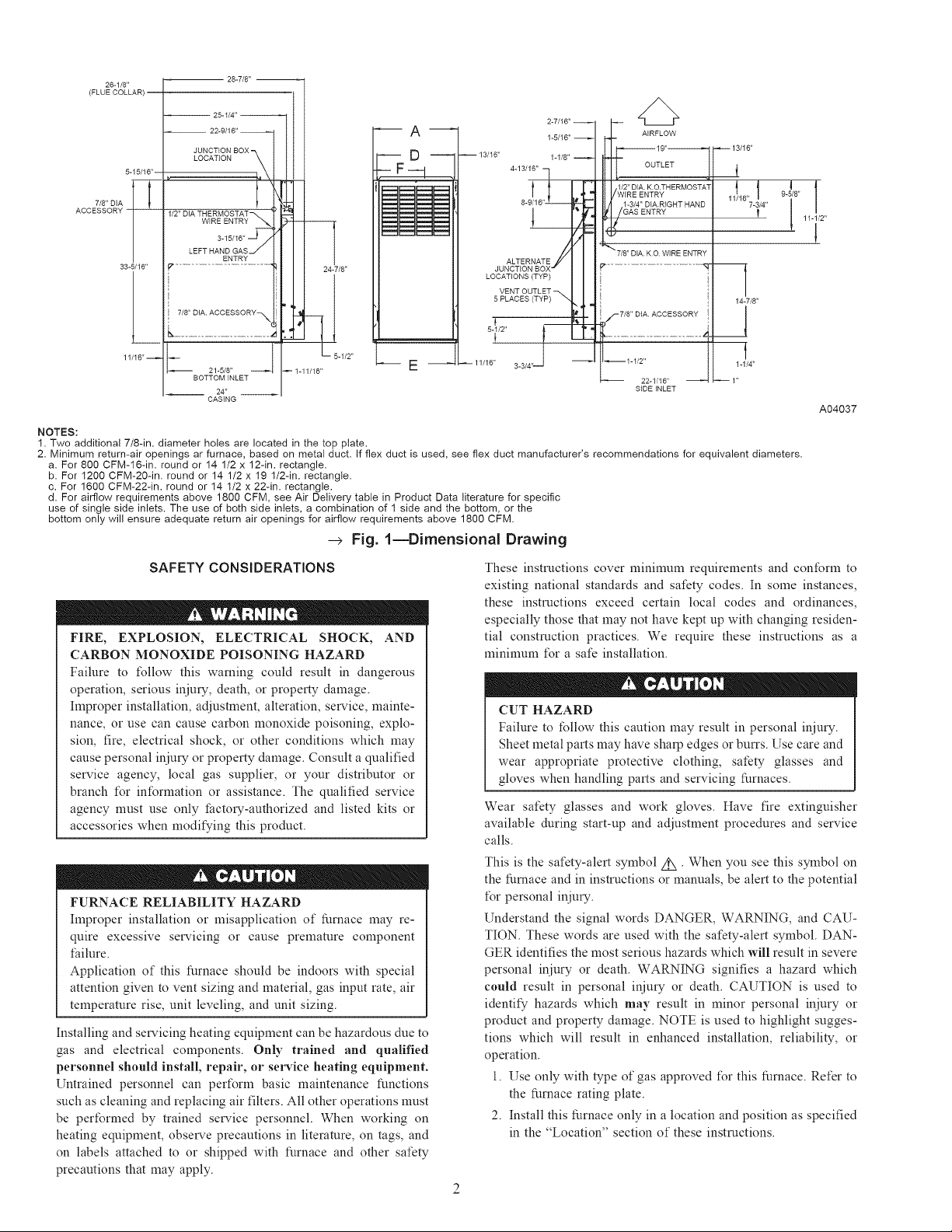
NOTES:
1. Two additional 7/8-in. diameter holes are located in the top plate.
2. Minimum return-air openings ar furnace, based on metal duct. If flex duct is used, see flex duct manufacturer's recommendations for equivalent diameters.
a. For 800 CFM-16-in. round or 14 1/2 x 12-in. rectangle.
b. For 1200 CFM-20-in. round or 14 1/2 x 19 1/2-in. rectangle.
c. For 1600 CFM-22-in. round or 14 1/2 x 22-in. rectangle.
d. For airflow requirements above 1800 CFM, see Air Delivery table in Product Data literature for specific
use of single side inlets. The use of both side inlets, a combination of 1 side and the bottom, or the
bottom only will ensure adequate return air openings for airflow requirements above 1800 CFM.
--> Fig. l mDimensional Drawing
SAFETY CONSIDERATIONS
FIRE, EXPLOSION, ELECTRICAL SHOCK, AND
CARBON MONOXIDE POISONING HAZARD
Failure to l\_llow this warning could result in dangerous
operation, serious injmT, death, or property damage.
hnproper installation, adjustment, alteration, service, mainte-
nance, or use can cause carbon monoxide poisoning, explo-
sion, fire, electrical shock, or other conditions which may
cause personal injmT or property damage. Consult a qualified
service agency, local gas supplier, or your distributor or
branch t\_r int\_rnaation or assistance. The qualified service
agency must use only factolT-authorized and listed kits or
accessories when modifying this product.
FURNACE RELIABILITY HAZARD
hnproper installation or misapplication of furnace may re-
quire excessive servicing or cause premature component
I:ailure.
Application of this furnace should be indoors with special
attention given to vent sizing and material, gas input rate, air
temperature rise, unit leveling, and unit sizing.
Installing and servicing heating equipment can be hazardous due to
gas and electrical components. Only trained and qualified
personnel should install, repair, or service heating equipment.
Untrained personnel can pert\_rm basic maintenance functions
such as cleaning and replacing air filters. All other operations must
be performed by trained service personnel. When working on
heating equipment, observe precautions in literature, on tags, and
on labels attached to or shipped with furnace and other safety
precautions that may apply.
These instructions cover mininmm requirements and conform to
existing national standards and safety codes. In some instances,
these instructions exceed certain local codes and ordinances,
especially those that may not have kept up with changing residen-
tial construction practices. We require these instructions as a
mininmm t\_r a safe installation.
CUT HAZARD
Failure to follow this caution may result in personal injury.
Sheet metal parts may have sharp edges or burrs. Use care and
wear appropriate protective clothing, safety glasses and
gloves when handling parts and servicing furnaces.
Wear safety glasses and work gloves. Have fire extinguisher
available during start-up and adjustment procedures and service
calls.
This is the safety-alert symbol/!X •When you see this symbol on
the furnace and in instructions or manuals, be alert to the potential
t\_r personal injmT.
Understand the signal words DANGER, WARNING, and CAU-
TION. These words are used with the safety-alert symbol. DAN-
GER identifies the most serious hazards which will result in severe
personal injury or death. WARNING signifies a hazard which
could result in personal injmy or death. CAUTION is used to
identity hazards which may result in minor personal injury or
product and property damage. NOTE is used to highlight sugges-
tions which will result in enhanced installation, reliability, or
operation.
1. Use only with type of gas approved t\_r this furnace. Refer to
the furnace rating plate.
2. Install this furnace only in a location and position as specified
in the "Location" section of these instructions.
A04037
iNSTALLATiON
MiNiMUM INCHES CLEARANCE TO COMBUSTIBLE CONSTRUCTION
DISTANCE MINIMALE EN POUCES AUX CONSTRUCTIONS COMBUSTIBLES
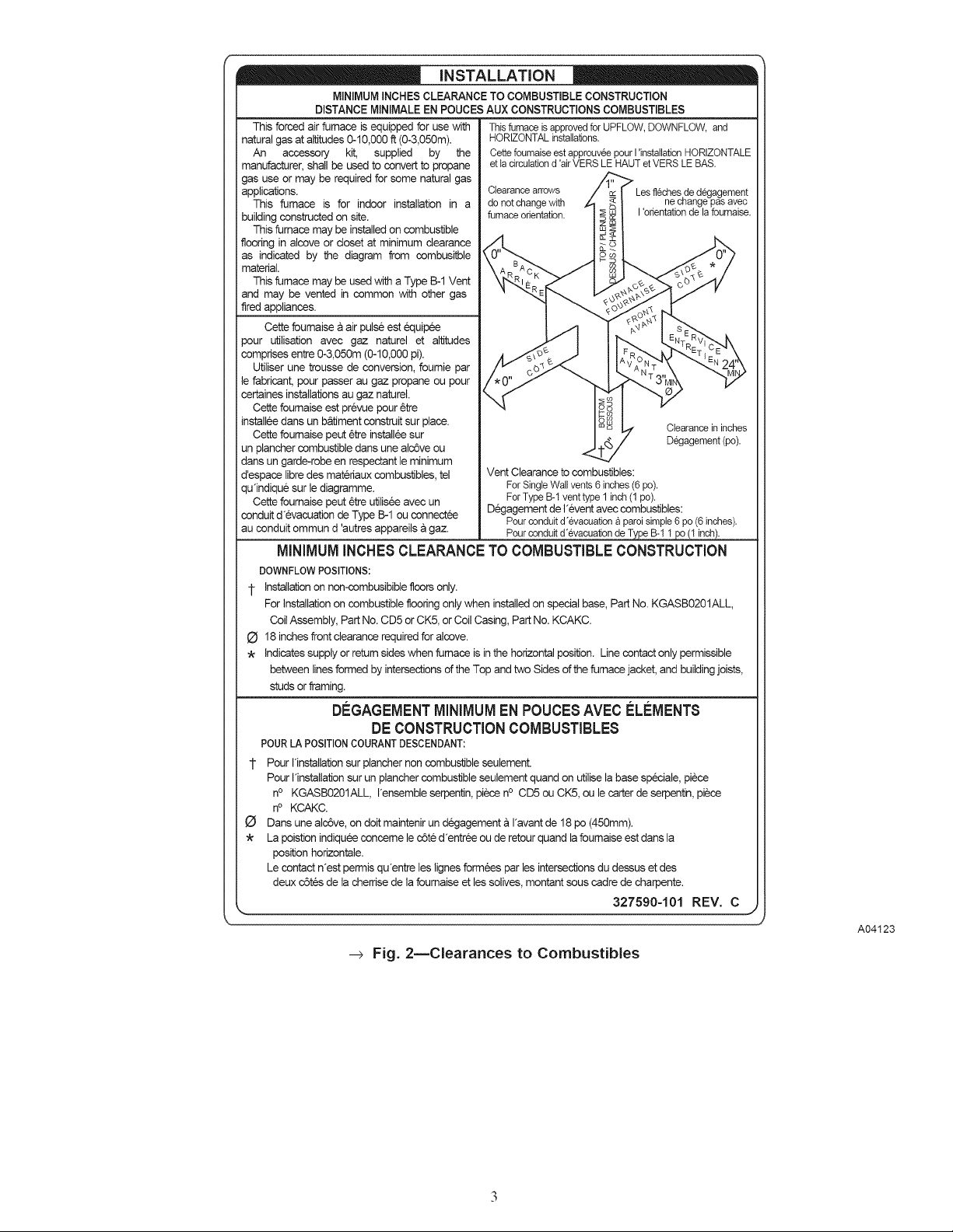
This forced air furnace is equipped for use with Thisfurnace is approvedfor UPFLOW, DOWNFLOW, and
natural gas at altitudes 0-10,000 ft (0-3,050m). HORIZONTAL installations.
An accessory kit, supplied by the Cette foumaiseestapprouvee pour I 'installationHORIZONTALE
manufacturer, shall be used to convert to propane et lacirculationd 'airVERS LE HAUT etVERS LE BAS.
gas use or may be required for some natural gas
applications. Clearance arrows /'_1 Lesflechesdedecjagement
This furnace is for indoor installation in a donot change with _ _ I ne change pas avec
building constructed on site.
This furnace may be installed on combustible
as indicated by the diagram from combusitble
fiooring in alcove or closet at minimum clearance _B.A_cK_.. j i_-
material.
This furnace may be used with a Type B-1 Vent ._'_R E .Q _15_._ co j_/
and may be vented in common with other gas _" "_- _,_-__,,'f V
fired appliances. -.,._., i._,_ _o_._
pour utilisation avec gaz naturel et altitudes
comprises entre 0-3,050m (0-10,000 pi).
Cette foumaise a air pulse est 6quipde _cb9 _ __%
Utiliser une trousse de conversion, foumie par
le fabricant, pour passer au gaz propane ou pour / _0" ,,..,,,,'_ _ , f>,,,,, ' 3'_ "_
certaines installations au gaz naturel. \ /
Cette foumaise est prevue pour 6tre _ _ _
installee dens un b_timent construit sur place. 2 W _/ Clearancein inches
Cette foumaise peut 6tre installee sur _ / Degagement (pc).
un plancher combustible dens une alcdve ou _-- t"'/
dens un garde-robe en respectant le minimum
d'espace libre des materiaux combustibles, tel Vent Clearance to combustibles:
qu'indique sur le diagramme. ForSingleWallvents 6 inches(6 pc).
Cette foumaise peut 6tre utilisee avec un
conduit d'evacuation de Type B-1 ou connectee Pour conduitd'evacuation a paroisimple6 pc (6 inches).
au conduit ommun d 'autres appareils a gaz. Pourconduitd'evacuation deType B-1 1pc (1 inch).
furnaceorientation. ____I I'orientationde la fournaise.
o4
ForType B-1 venttype 1 inch(1 pc).
Degagement de I'event avec combustibles:
MINIMUMINCHES CLEARANCETO COMBUSTIBLE CONSTRUCTION
DOWNFLOW POSITIONS:
1- Installation on non-combusibible floors only.
For Installation on combustible flooring only when installed on special base, Part No. KGASB0201ALL,
Coil Assembly, Part No. CD5 or CKS, or Coil Casing, Part No. KCAKC.
18 inches front clearance required for alcove.
Indicates supply or return sides when furnace is in the horizontal position. Line contact only permissible
between lines formed by intersections of the Top and two Sides of the furnace jacket, and building joists,
studs or framing.
BEGAGEMENTMINIMUM EN POUCESAVEC €=LI_MENTS
DECONSTRUCTION COMBUSTIBLES
POUR LA POSITIONCOURANTDESCENDANT:
1- Pour Hnstallation sur plancher non combustible seulement.
Pour I'installation sur un plancher combustible seulement quand on utilise la base speciale, piece
no KGASB0201ALL, I'ensemble serpentin, piece no CD5 ou CK5, ou le carter de serpentin, piece
no KCAKC.
Dens une alcdve, on dolt maintenir un degagement a I'avant de 18 pc (450mm).
La poistion indiquee conceme le cdte d'entree ou de retour quand la foumaise est dens la
position horizontale.
Le contact n'est permis qu'entre les lignes formees par les intersections du dessus et des
deux cdtes de la cherrise de la foumaise et les solives, montant sous cadre de charpente.
327590-101 REV. C
--> Fig. 2_Clearances to Combustibles
A04123
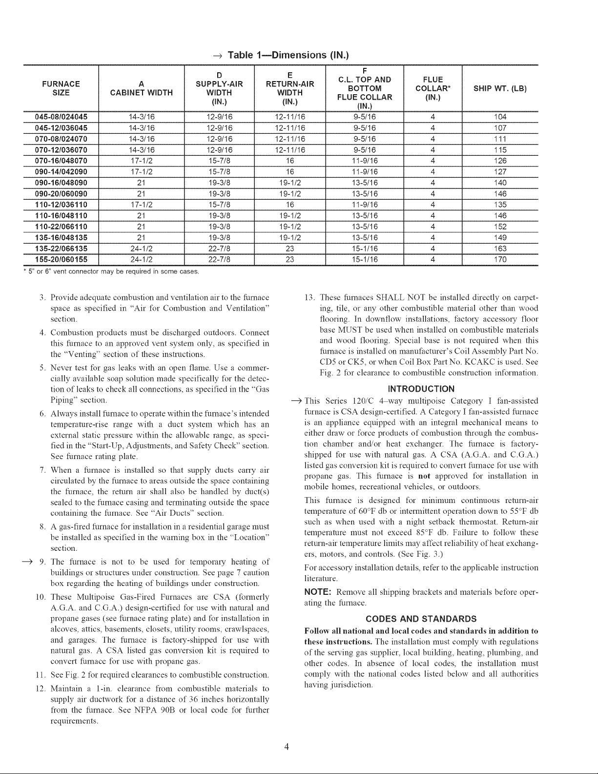
Table lmDimensions (iN.)
FURNACE A SUPPLY-AIR RETURN-AIR
SiZE CABINET WIDTH WIDTH WIDTH
045-081024045 14-3/16 12-9/16 12-11/16 9-5/16 4 104
045-121036045 14-3/16 12-9/16 12-11/16 9-5/16 4 107
070-081024070 14-3/16 12-9/16 12-11/16 9-5/16 4 111
070-121036070 14-3/16 12-9/16 12-11/16 9-5/16 4 115
070-161048070 17-1/2 15-7/8 16 11-9/16 4 126
090-141042090 17-1/2 15-7/8 16 11-9/16 4 127
090-161048090 21 19-3/8 19-1/2 13-5/16 4 140
090-201060090 21 19-3/8 19-1/2 13-5/16 4 146
110-121036110 17-1/2 15-7/8 16 11-9/16 4 135
110-161048110 21 19-3/8 19-1/2 13-5/16 4 146
110-221066110 21 19-3/8 19-1/2 13-5/16 4 152
135-16/048135 21 19-3/8 19-1/2 13-5/16 4 149
135-221066135 24-1/2 22-7/8 23 15-1/16 4 163
155-201060155 24-1/2 22-7/8 23 15-1/16 4 170
* 5"or 6" vent connector may be required insome cases.
3.
Provide adequate combustion and ventilation air to the furnace
space as specified in "Air t\_r Combustion and Ventilation"
section.
4. Combustion products must be discharged outdoors. Connect
this furnace to an approved vent system only, as specified in
the "Venting" section of these instructions.
5. Never test t_r gas leaks with an open flame. Use a commer-
cially available soap solution made specifically t\_r the detec-
D E
(iN.) (iN.) (iN.)
13. These furnaces SHALL NOT be installed directly on carpet-
ing, tile, or any other combustible material other than wood
flooring. In downflow installations, factoiT accessoi T floor
base MUST be used when installed on combustible materials
and wood flooring. Special base is not required when this
furnace is installed on manufacturer's Coil Assembly Part No.
CD5 or CK5, or when Coil Box Part No. KCAKC is used. See
Fig. 2 t\_r clearance to combustible construction int\_rmation.
tion of leaks to check all connections, as specified in the "Gas
Piping" section.
6. Always install furnace to operate within the furnace's intended
temperature-rise range with a duct system which has an
external static pressure within the allowable range, as speci-
fied in the "Start-Up, Adjustments, and Safety Check" section.
See furnace rating plate.
7. When a furnace is installed so that supply ducts carry air
circulated by the furnace to areas outside the space containing
the furnace, the return air shall also be handled by duct(s)
sealed to the furnace casing and terminating outside the space
containing the furnace. See "Air Ducts" section.
8. A gas-fired furnace t_r installation in a residential garage nmst
be installed as specified in the warning box in the "Location"
section.
--->
9. The furnace is not to be used t_r temporm T heating of
buildings or structures under construction. See page 7 caution
box regarding the heating of buildings under construction.
10. These Multipoise Gas-Fired Furnaces are CSA (t_rmerly
A.G.A. and C.G.A.) design-certified t\_r use with natural and
--->
This Series 120/C 4way multipoise Categoi T I fan-assisted
furnace is CSA design-certified. A Category I fan-assisted furnace
is an appliance equipped with an integral mechanical means to
either draw or t\_rce products of combustion through the combus-
tion chamber and/or heat exchanger. The furnace is factory-
shipped t_r use with natural gas. A CSA (A.G.A. and C.G.A.)
listed gas conversion kit is required to convert furnace t_r use with
propane gas. This furnace is not approved t\_r installation in
mobile homes, recreational vehicles, or outdoors.
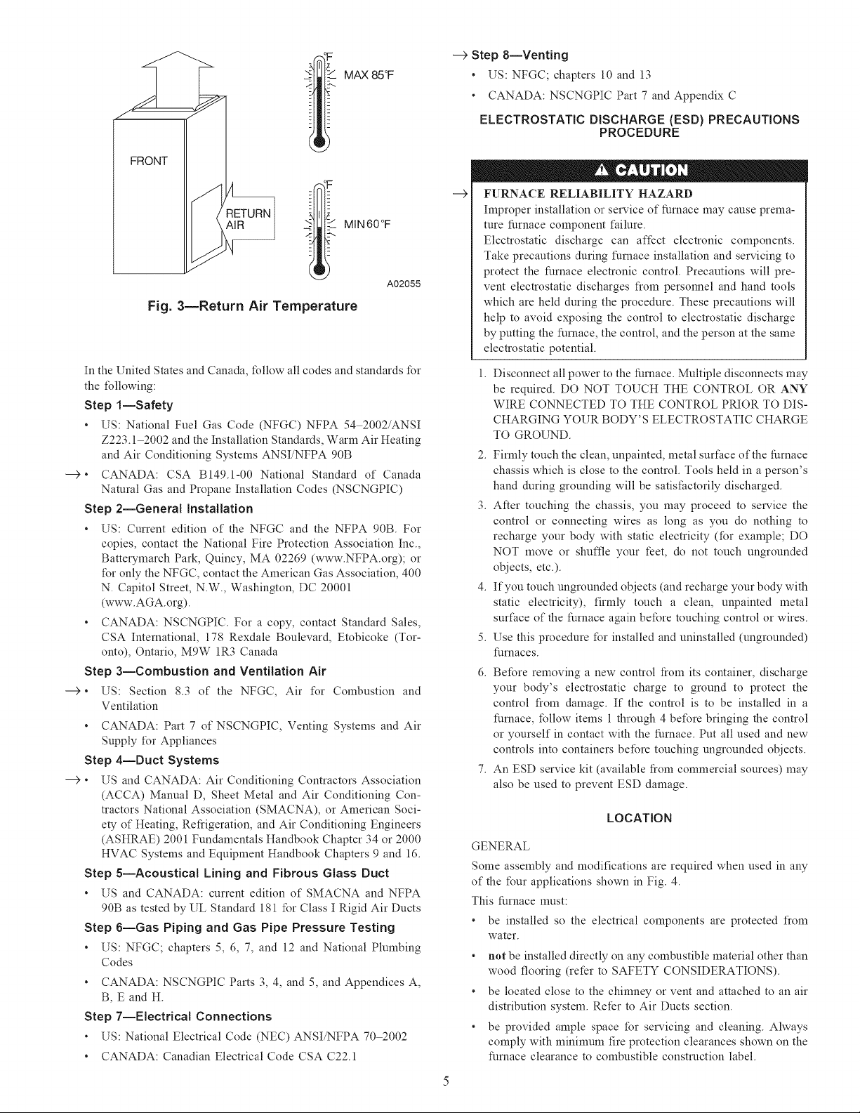
This furnace is designed t\_r mininmm confumous return-air
temperature of 60°F db or intermittent operation down to 55°F db
such as when used with a night setback thermostat. Return-air
temperature must not exceed 85°F db. Failure to t\_llow these
return-air temperature limits may affect reliability of heat exchang-
ers, motors, and controls. (See Fig. 3.)
For accessoiT installation details, refer to the applicable instruction
literature.
NOTE: Remove all shipping brackets and materials bet_re oper-
ating the furnace.
propane gases (see furnace rating plate) and t_r installation in
alcoves, attics, basements, closets, utility rooms, crawlspaces,
and garages. The furnace is factolT-shipped t\_r use with
natural gas. A CSA listed gas conversion kit is required to
convert furnace t\_r use with propane gas.
11. See Fig. 2 t\_rrequired clearances to combustible construction.
12. Maintain a 1-in. clearance fiom combustible materials to
Follow all national and local codes and standards in addition to
these instructions. The installation nmst comply with regulations
of the serving gas supplier, local building, heating, plmnbing, and
other codes. In absence of local codes, the installation must
comply with the national codes listed below and all authorities
having jurisdiction.
supply air ductwork t\_r a distance of 36 inches horizontally
from the furnace. See NFPA 90B or local code t\_r further
requirements.
F
C.L. TOP AND FLUE
BOTTOM COLLAR* SHiP WT. (LB)
FLUE COLLAR (iN.)
INTRODUCTION
CODES AND STANDARDS
°ii- _ MAX 85°F
_I I MING0°F
A02055
Fig. 3mReturn Air Temperature
In the United States and Canada, follow all codes and standards for
the following:
Step 1--Safety
, US: National Fuel Gas Code (NFGC) NFPA 54 2002/ANSI
Z223.1 2002 and the Installation Standards, Warm Air Heating
and Air Conditioning Systems ANSI/NFPA 90B
--€, CANADA: CSA B149.1-00 National Standard of Canada
Natural Gas and Propane Installation Codes (NSCNGPIC)
Step 2--General Installation
, US: Current edition of the NFGC and the NFPA 90B. For
copies, contact the National Fire Protection Association Inc.,
BattmTmarch Park, Quincy, MA 02269 (www.NFPA.org); or
for only the NFGC, contact the American Gas Association, 400
N. Capitol Street, N.W., Washington, DC 20001
(www.AGA.org).
, CANADA: NSCNGPIC. For a copy, contact Standard Sales,
CSA International, 178 Rexdale Boulevard, Etobicoke (Tor-
onto), Ontario, Mgw 1R3 Canada
Step a--Combustion and Ventilation Air
--€, US: Section 8.3 of the NFGC, Air I\)r Combustion and
Ventilation
, CANADA: Part 7 of NSCNGPIC, Venting Systems and Air
Supply I\)r Appliances
Step 4--Duct Systems
--€, US and CANADA: Air Conditioning Contractors Association
(ACCA) Manual D, Sheet Metal and Air Conditioning Con-
tractors National Association (SMACNA), or American Soci-
ety of Heating, Refiigeration, and Air Conditioning Engineers
(ASHRAE) 2001 Fundamentals Handbook Chapter 34 or 2000
HVAC Systems and Equipment Handbook Chapters 9 and 16.
Step 5--Acoustical Lining and Fibrous Glass Duct
, US and CANADA: current edition of SMACNA and NFPA
90B as tested by UL Standard 181 for Class I Rigid Air Ducts
Step 6--Gas Piping and Gas Pipe Pressure Testing
US: NFGC; chapters 5, 6, 7, and 12 and National Plmnbing
Codes
, CANADA: NSCNGPIC Parts 3, 4, and 5, and Appendices A,
B, E and H.
Step 7--Electrical Connections
, US: National Electrical Code (NEC) ANSI/NFPA 702002
, CANADA: Canadian Electrical Code CSA C22.1
--->Step 8--Venting
, US: NFGC; chapters 10 and 13
, CANADA: NSCNGPIC Part 7 and Appendix C
ELECTROSTATIC DISCHARGE (ESD) PRECAUTIONS
PROCEDURE
FURNACE RELIABILITY HAZARD
hnproper installation or service of furnace may cause prema-
ture furnace component failure.
Electrostatic discharge can affect electronic components.
Take precautions during furnace installation and servicing to
protect the furnace electronic control. Precautions will pre-
vent electrostatic discharges from personnel and hand tools
which are held during the procedure. These precautions will
help to avoid exposing the control to electrostatic discharge
by putting the furnace, the control, and the person at the same
electrostatic potential.
Disconnect all power to the furnace. Multiple disconnects may
be required. DO NOT TOUCH THE CONTROL OR ANY
WIRE CONNECTED TO THE CONTROL PRIOR TO DIS-
CHARGING YOUR BODY'S ELECTROSTATIC CHARGE
TO GROUND.
2. Firmly touch the clean, unpainted, metal surt:ace of the furnace
chassis which is close to the control. Tools held in a person's
hand during grounding will be satisfactorily discharged.
3. After touching the chassis, you may proceed to smwice the
control or connecting wires as long as you do nothing to
recharge your body with static electricity (for example; DO
NOT move or shuffle your feet, do not touch ungrounded
objects, etc.).
4. If you touch ungrounded objects (and recharge your body with
static electricity), firmly touch a clean, unpainted metal
surt:ace of the furnace again before touching control or wires.
5.
Use this procedure for installed and uninstalled (ungrounded)
furnaces.
6.
Before removing a new control fiom its container, discharge
your body's electrostatic charge to ground to protect the
control fiom damage. If the control is to be installed in a
furnace, follow items 1 through 4 bet\)re bringing the control
or yourself in contact with the furnace. Put all used and new
controls into containers before touching ungrounded objects.
An ESD service kit (available fiom commercial sources) may
also be used to prevent ESD damage.
LOCATION
GENERAL
Some assembly and modifications are required when used in any
of the four applications shown in Fig. 4.
This furnace must:
, be installed so the electrical components are protected flom
water.
, not be installed directly on any combustible material other than
wood flooring (refer to SAFETY CONSIDERATIONS).
, be located close to the chinmey or vent and attached to an air
distribution system. Refer to Air Ducts section.
, be provided ample space for smwicing and cleaning. Always
comply with mininmm fire protection clearances shown on the
furnace clearance to combustible construction label.
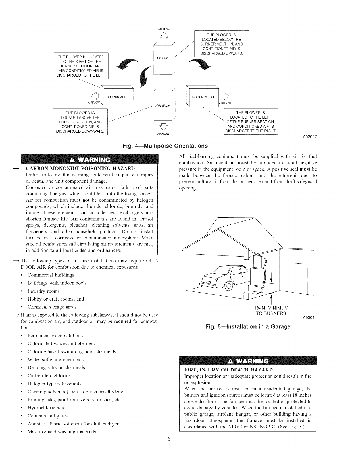
THE BLOWER IS LOCATED
BURNER SECTION, AND
AIR CONDITIONED AIR IS
DISCHARGED TO THE LEFT.
TO THE RIGHT OF THE t
THE BLOWER IS
LOCATED ABOVE THE
BURNER SECTION, AND
CONDITIONED AIR IS
DISCHARGED DOWNWARD
Fig. 4mMuitipoise Orientations
--> CARBON MONOXIDE POISONING HAZARD
Failure to follow this warning could result in personal injury
or death, and unit component damage.
Corrosive or contaminated air may cause failure of parts
containing flue gas, which could leak into the living space.
Air for combustion must not be contaminated by halogen
compounds, which include fluoride, chloride, bromide, and
iodide. These elements can corrode heat exchangers and
shorten furnace life. Air contaminants are t\mnd in aerosol
sprays, detergents, bleaches, cleaning solvents, salts, air
fresheners, and other household products. Do not install
furnace in a corrosive or contaminated atmosphere. Make
sure all combustion and circulating air requirements are met,
in addition to all local codes and ordinances.
THE BLOWER IS
LOCATED BELOW THE
BURNER SECTION, AND
CONDITIONED AIR IS
DISCHARGED UPWARD.
HORIZONTAL RIGHT
q IAIRFLOW
LOCATED TO THE LEFT
OF THE BURNER SECTION,
AND CONDITIONED AIR IS
THE BLOWER IS
DISCHARGED TO THE RIGHT.
A02097
All fuel-burning equipment must be supplied with air t\_r fuel
combustion. Sufficient air must be provided to avoid negative
pressure in the equipment room or space. A positive seal must be
made between the furnace cabinet and the return-air duct to
prevent pulling air fiom the burner area and fiom draft safeguard
opening.
---5 The t\_llowing types of furnace installations may require OUT-
DOOR AIR for combustion due to chemical exposures:
. Commercial buildings
. Buildings with indoor pools
. Lanndi T rooms
. Hobby or craft rooms, and
• Chemical storage areas
---5 If air is exposed to the tMlowing substances, it should not be used
for combustion air, and outdoor air may be required for combus-
tion:
. Permanent wave solutions
. Chlorinated waxes and cleaners
. Chlorine based swimming pool chemicals
. Water softening chemicals
. De-icing salts or chemicals
. Carbon tetrachloride
. Halogen type refrigerants
. Cleaning solvents (such as perchloroethylene)
. Printing inks, paint removers, varnishes, etc.
. Hydrochloric acid
. Cements and glues
. Antistatic t;abric softeners t\_r clothes dlTers
. Masom T acid washing materials
18-1N. MINIMUM
TO BURNERS
A93044
Fig. 5mlnstallation in a Garage
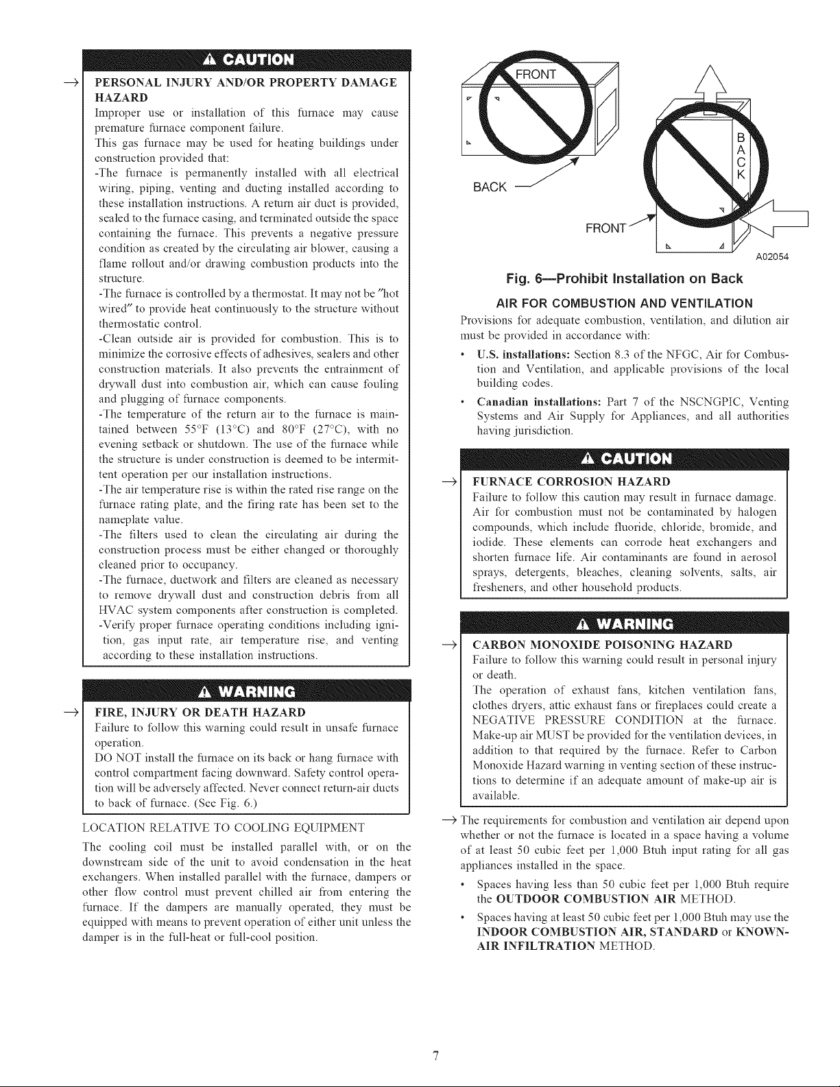
FIRE, INJURY OR DEATH HAZARD
hnproper location or inadequate protection could result in fire
or explosion.
When the furnace is installed in a residential garage, the
burners and ignition sources must be located at least 18 inches
above the floor. The furnace must be located or protected to
avoid damage by vehicles. When the furnace is installed in a
public garage, airplane hangar, or other building having a
hazardous atmosphere, the furnace must be installed in
accordance with the NFGC or NSCNGPIC. (See Fig. 5.)
-__>
PERSONALINJURY AND/OR PROPERTY DAMAGE
HAZARD
Improper use or installation of this furnace may cause
premature furnace component t:ailure.
This gas furnace may be used I\)r heating buildings under
construction provided that:
-The furnace is permanently installed with all electrical
wiring, piping, venting and ducting installed according to
these installation instructions. A return air duct is provided,
sealed to the furnace casing, and terminated outside the space
containing the furnace. This prevents a negative pressure
condition as created by the circulating air blower, causing a
flame rollout and/or &awing combustion products into the
structure.
-The furnace is controlled bya thermostat. It may not be "hot
wired" to provide heat continuously to the structure without
thermostatic control.
-Clean outside air is provided for combustion. This is to
minimize the corrosive effects of adhesives, sealers and other
construction materials. It also prevents the entrainment of
&Twall dust into combustion air, which can cause fouling
and plugging of furnace components.
-The temperature of the return air to the furnace is main-
rained between 55°F (13°C) and 80°F (27°C), with no
evening setback or shutdown. The use of the furnace while
the structure is under construction is deemed to be intermit-
tent operation per our installation instructions.
-The air temperature rise is within the rated rise range on the
furnace rating plate, and the firing rate has been set to the
nameplate value.
-The filters used to clean the circulating air during the
construction process nmst be either changed or thoroughly
cleaned prior to occupancy.
-The furnace, ductwork and filters are cleaned as necessm T
to remove &ywall dust and construction debris from all
HVAC system components after construction is completed.
-Verify proper furnace operating conditions including igni-
tion, gas input rate, air telnperamre rise, and venting
according to these installation instructions.
-__>
FIRE, INJURY OR DEATH HAZARD
Failure to t\)llow this warning could result in unsafe furnace
operation.
DO NOT install the furnace on its back or hang furnace with
control compartment facing downward. Safety control opera-
tion will be adversely affected. Never connect return-air ducts
to back of furnace. (See Fig. 6.)
LOCATION RELATIVE TO COOLING EQUIPMENT
The cooling coil nmst be installed parallel with, or on the
downstream side of the unit to avoid condensation in the heat
exchangers. When installed parallel with the furnace, dampers or
other flow control nmst prevent chilled air from entering the
furnace. If the dampers are manually operated, they nmst be
equipped with means to prevent operation of either unit unless the
damper is in the full-heat or full-cool position.
BACK S
FR(
A02054
Fig. 6mProhibit Installation on Back
AIR FOR COMBUSTION AND VENTILATION
Provisions t\)r adequate combustion, ventilation, and dilution air
nmst be provided in accordance with:
, U.S. installations: Section 8.3 of the NFGC, Air for Combus-
tion and Ventilation, and applicable provisions of the local
building codes.
, Canadian installations: Part 7 of the NSCNGPIC, Venting
Systems and Air Supply t\)r Appliances, and all authorities
having jurisdiction.
FURNACE CORROSION HAZARD
Failure to t\)llow this caution may result in furnace damage.
Air for combustion nmst not be contaminated by halogen
compounds, which include fluoride, chloride, bromide, and
iodide. These elements can corrode heat exchangers and
shorten furnace life. Air contaminants are found in aerosol
sprays, detergents, bleaches, cleaning solvents, salts, air
ffesheners, and other household products.
---> CARBON MONOXIDE POISONING HAZARD
Failure to t\)llow this warning could result in personal injury
or death.
The operation of exhaust t:ans, kitchen ventilation tans,
clothes dwers, attic exhaust tans or fireplaces could create a
NEGATIVE PRESSURE CONDITION at the furnace.
Make-up air MUST be provided for the ventilation devices, in
addition to that required by the furnace. Refer to Carbon
Monoxide Hazard warning in venting section of these instruc-
tions to determine if an adequate amount of make-up air is
available.
--->The requirements for combustion and ventilation air depend upon
whether or not the furnace is located in a space having a volmne
of at least 50 cubic feet per 1,000 Btuh input rating for all gas
appliances installed in the space.
, Spaces having less than 50 cubic feet per 1,000 Btuh require
the OUTDOOR COMBUSTION AIR METHOD.
, Spaces having at least 50 cubic feet per 1,000 Bmh may use the
INDOOR COMBUSTION AIR, STANDARD or KNOWN-
AIR INFILTRATION METHOD.
--€
FURNACE
(BTUH)
110,000
132,000
154,000
iNPUT
44,000
66,000
88,000
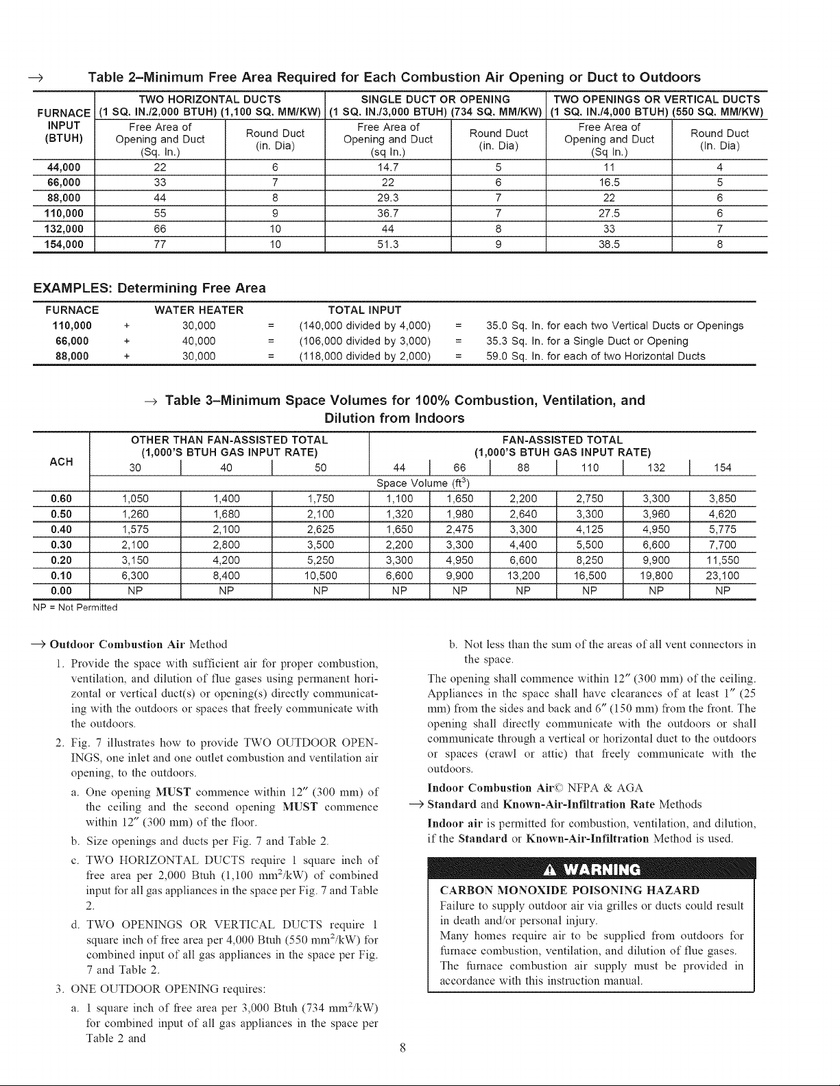
Table 2-Minimum Free Area Required for Each Combustion Air Opening or Duct to Outdoors
TWO HORIZONTAL DUCTS SINGLE DUCT OR OPENING TWO OPENINGS OR VERTICAL DUCTS
i(1 SQ. IN./2,000 BTUH)
Free Area of
Opening and Duct
(Sq. In.)
22
33
44
55
66
77
(1,100 SQ. MM/KW)
Round Duct
(in. Dia)
6
7
8
9
10
10
(1 SQ. IN./3,000 BTUH)
Free Area of
Opening and Duct
(sq In.)
14.7
22
29.3
36.7
44
51.3
(734 SQ. MM/KW)
Round Duct
(in. Dia)
5
6
7
7
8
9
(1 SQ. IN./4,000 BTUH)
Free Area of
Opening and Duct
(Sq In.)
11
16.5
22
27.5
33
38.5
(550 SQ. MM/KW)
EXAMPLES: Determining Free Area
FURNACE WATER HEATER TOTAL iNPUT
110,000 + 30,000 = (140,000 divided by 4,000) = 35.0 Sq. In. for each two Vertical Ducts or Openings
66,000 + 40,000 = (106,000 divided by 3,000) = 35.3 Sq. In. for a Single Duct or Opening
88,000 + 30,000 = (118,000 divided by 2,000) = 59.0 Sq. In. for each of two Horizontal Ducts
--> Table 3=Minimum Space Volumes for 100% Combustion, Ventilation, and
Dilution from Indoors
OTHER THAN FAN-ASSISTED TOTAL T FAN-ASSISTED TOTAL
Round Duct
(in. Dia)
4
5
6
6
7
8
ACH 30 I 40 I 50 44 !66 ! 88 I 110 I 132 1154
0.60 1,050 1,400 1,750 1,100 1,650 2,200 2,750 3,300 3,850
0.50 1,260 1,680 2,100 1,320 1,980 2,640 3,300 3,960 4,620
0.40 1,575 2,100 2,625 1,650 2,475 3,300 4,125 4,950 5,775
0.30 2,100 2,800 3,500 2,200 3,300 4,400 5,500 6,600 7,700
0.20 3,150 4,200 5,250 3,300 4,950 6,600 8,250 9,900 11,550
0.10 6,300 8,400 10,500 6,600 9,900 13,200 16,500 19,800 23,100
0.00 NP NP NP NP NP NP NP NP NP
NP = Not Permitted
---> Outdoor Combustion Air Method
1. Provide the space with sufficient air for proper combustion,
ventilation, and dilution of flue gases using permanent hori-
zontal or vertical duct(s) or opening(s) directly communicat-
ing with the outdoors or spaces that tieely communicate with
the outdoors.
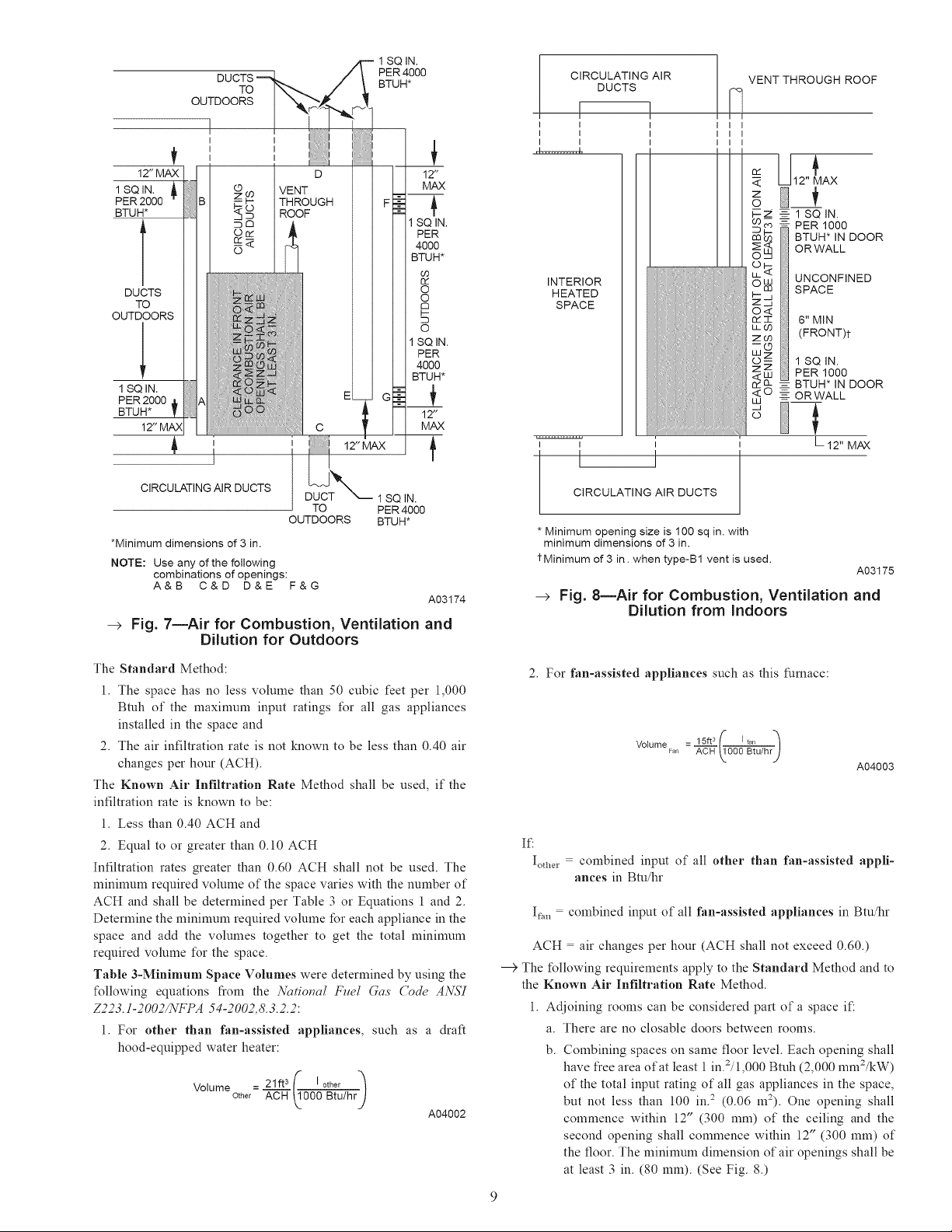
2. Fig. 7 illustrates how to provide TWO OUTDOOR OPEN-
INGS, one inlet and one outlet combustion and ventilation air
opening, to the outdoors.
a. One opening MUST commence within 12" (300 mm) of
the ceiling and the second opening MUST commence
within 12" (300 mm) of the floor.
b. Size openings and ducts per Fig. 7 and Table 2.
(1,000'S BTUH GAS INPUT RATE) / (1,000'S BTUH GAS INPUT RATE)
Space Volume (ft3)
b. Not less than the stun of the areas of all vent connectors in
the space.
The opening shall commence within 12" (300 mm) of the ceiling.
Appliances in the space shall have clearances of at least 1" (25
mln) from the sides and back and 6" (150 mm) Iiom the Iiont. The
opening shall directly conmmnicate with the outdoors or shall
conmmnicate through a vertical or horizontal duct to the outdoors
or spaces (crawl or attic) that tieely communicate with the
outdoors.
Indoor Combustion Air(c) NFPA & AGA
---> Standard and Known-Air-Infiltration Rate Methods
Indoor air is permitted for combustion, ventilation, and dilution,
if the Standard or Known-Air-Infiltration Method is used.
c. TWO HORIZONTAL DUCTS require 1 square inch of
tiee area per 2,000 Btuh (1,100 mn12/kW) of combined
input for all gas appliances in the space per Fig. 7 and Table
2.
TWO OPENINGS OR VERTICAL DUCTS require 1
square inch of tiee area per 4,000 Btuh (550 mn12/kW) for
combined input of all gas appliances in the space per Fig.
7 and Table 2.
3. ONE OUTDOOR OPENING requires:
CARBON MONOXIDE POISONING HAZARD
Failure to supply outdoor air via grilles or ducts could result
in death and/or personal injury.
Many homes require air to be supplied tiom outdoors t\_r
furnace combustion, ventilation, and dilution of flue gases.
The furnace combustion air supply must be provided in
accordance with this instruction manual.
a. 1 square inch of tiee area per 3,000 Btuh (734 mm2/kW)
for combined input of all gas appliances in the space per
Table 2 and
1 SQ IN.
PER 4000
BTUH*
+
OUTDOORS
I
I
I
TO
D 1:
o9 VENT MAX
F+
_r_ 1SC
o r_ PE
BTL
69
O2
o
!M O
_'C_ i 1BCIN.
_ 40(
_'; BTL
PER 2000
BTU_
12"MJ_Xj
CIRCULATING AIR DUCTS
*Minimum dimensions of 3 in.
NOTE: Use any of the following
combinations of openings:
A&B C&D D&E F&G
i 12" MAX
I
c M
TO PER 4000
OUTDOORS BTUH*
--> Fig. 7mAir for Combustion, Ventilation and
Dilution for Outdoors
1;
1SQ IN.
A03174
CIRCULATING AIR
DUCTS
VENT THROUGH ROOF
I I
I I
I I
I I
INTERIOR
HEATED
SPACE
I
I
I
_< 12" MAX
o
F-Z __- 1 SQ IN.
m__ PER 1000
O R WAL L
oOo_ BTUH*INDOOR
O_ UNCONFINED
..J SPACE
=_J
o<
O2-r 6" MIN
LL CO (FRONT)t
2O3
o- 1 SQ IN.
_+ PER1000
_ %- BTUH* IN DOOR
LJ
ORWALL
L12" MAX
I I
CIRCULATING AIR DUCTS
* Minimum opening size is 100 sq in. with
minimum dimensions of 3 in.
tMinimum of 3 in. when type-B1 vent is used.
--> Fig. 8mAir for Combustion, Ventilation and
Dilution from Indoors
A03175
The Standard Method:
1. The space has no less volmne than 50 cubic feet per 1,000
Btuh of the maximmn input ratings t\_r all gas appliances
installed in the space and
2. The air infiltration rate is not known to be less than 0.40 air
changes per hour (ACH).
The Known Air Infiltration Rate Method shall be used, if the
infiltration rate is known to be:
1. Less than 0.40 ACH and
2. Equal to or greater than 0.10 ACH
Infiltration rates greater than 0.60 ACH shall not be used. The
mininmm required volmne of the space varies with the number of
ACH and shall be determined per Table 3 or Equations 1 and 2.
Determine the minimmn required volmne for each appliance in the
space and add the volumes together to get the total mininmm
required volmne t\_r the space.
Table 3-Minimum Space Volmnes were determined by using the
t\_llowing equations from the Nutional Fllel Gas ('ode AN57
Z223.1-2002/NFPA 54-2002,8.3.2.2:
1. For other than fan-assisted appliances, such as a draft
hood-equipped water heater:
Volume _ 21ft 3 (" [other "_
Other ACH _000 Btu/hr!
A04002
2. For fan-assisted appliances such as this furnace:
Volume Fan AOH _!.000 Btu/hrj
: 15ft3_" I .... -_
A04003
If:
lothe 1 = combined input of all other than fan-assisted appli-
ances in Btu/hr
If++,+= combined input of all fan-assisted appliances in Btu/hr
ACH = air changes per hour (ACH shall not exceed 0.60.)
--€ The t\_llowing requirements apply to the Standard Method and to
the Known Air Infiltration Rate Method.
1. Adjoining rooms can be considered part of a space it'.
a. There are no closable doors between rooms.
b. Combining spaces on same floor level. Each opening shall
have free area of at least 1in.2/1,000 Bmh (2,000 mm2/kW)
of the total input rating of all gas appliances in the space,
but not less than 100 in.2 (0.06 m2). One opening shall
commence within 12" (300 mm) of the ceiling and the
second opening shall commence within 12" (300 mm) of
the floor. The n_inimum dimension of air openings shall be
at least 3 in. (80 mm). (See Fig. 8.)
c. Combining space on different floor levels. The volumes of
spaces on different floor levels shall be considered as
communicating spaces if connected by one or more perma-
nent openings in doors or floors having tiee area of at least
2 in.2/1,000 Btuh (4,400 mm2/kW) of total input rating of
all gas appliances.
2.
An attic or crawlspace may be considered a space that freely
communicates with the outdoors provided there are adequate
permanent ventilation openings directly to outdoors having
free area of at least 1-in.2/4,000 Bmh of total input rating t\_r
all gas appliances in the space.
3.
In spaces that use the Indoor Combustion Air Method,
infiltration should be adequate to provide air t\_r combustion,
permanent ventilation and dilution of flue gases. However, in
buildings with unusually tight construction, additional air
MUST be provided using the methods described in the
Outdoor Combustion Air Method section.
Unusually tight construction is defined as
Construction with:
a. Walls and ceilings exposed to the outdoors have a continu-
ous, sealed vapor barrier. Openings are gasketed or sealed
and
b. Doors and openable windows are weatherstripped and
c. Other openings are caulked or sealed. These include joints
around window and door frames, between sole plates and
floors, between wall-ceiling joints, between wall panels, at
penetrations I\_r plumbing, electrical and gas lines, etc.
---> Combination of Indoor and Outdoor Air
1. Indoor openings shall comply with the Indoor Combustion
Air Method below and,
2. Outdoor openings shall be located as required in the Outdoor
Combustion Air Method mentioned previously and,
3. Outdoor openings shall be sized as follows:
a. Calculate the Ratio of all Indoor Space volume divided by
required volume I\)r Indoor Combustion Air Method
below.
b. Outdoor opening size reduction Factor is 1 minus the
Ratio in a. above.
Minimum size of Outdoor openings shall be the size
required in Outdoor Combustion Air Method above
multiplied by reduction Factor in b. above. The minimum
dimension of air openings shall be not less than 3 in. (80
111m).
INSTALLATION
UPFLOW INSTALLATION
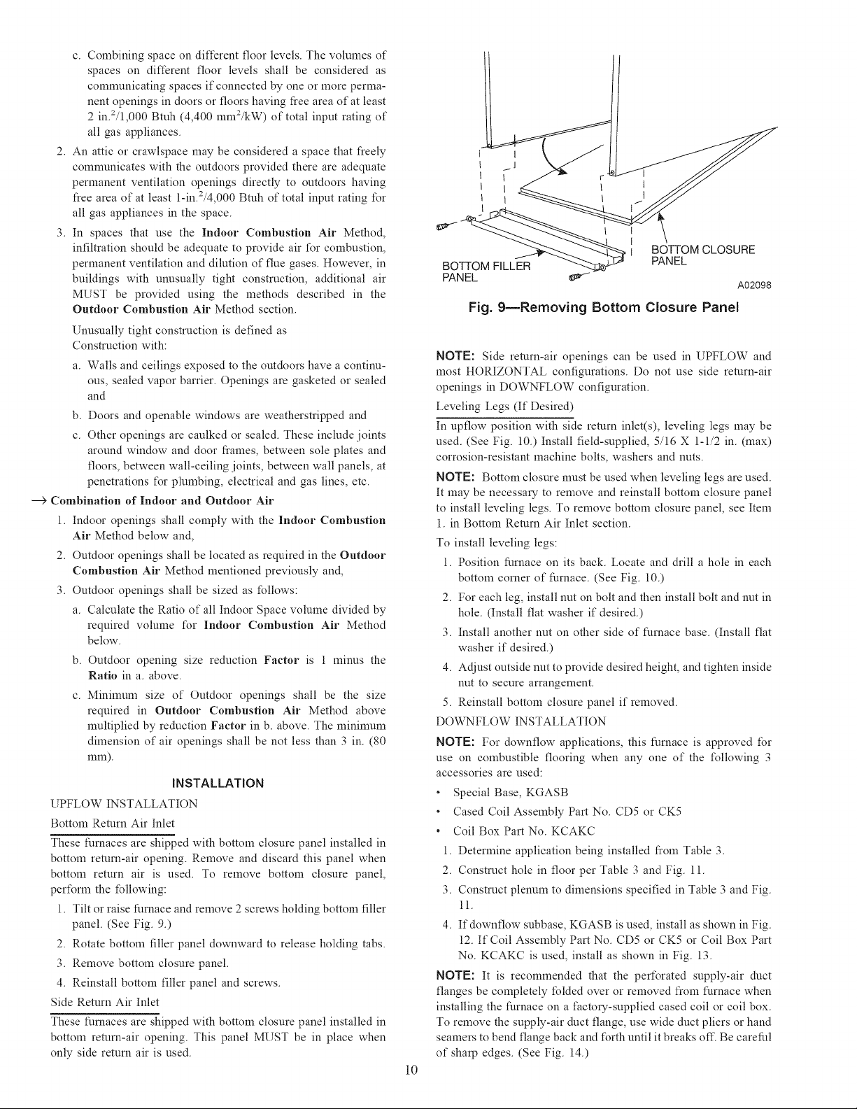
Bottom Return Air Inlet
These furnaces are shipped with bottom closure panel installed in
bottom return-air opening. Remove and discard this panel when
bottom return air is used. To remove bottom closure panel,
pert\_rm the following:
1. Tilt or raise furnace and remove 2 screws holding bottom filler
panel. (See Fig. 9.)
2. Rotate bottom filler panel downward to release holding tabs.
3. Remove bottom closure panel.
4. Reinstall bottom filler panel and screws.
Side Return Air Inlet
These furnaces are shipped with bottom closure panel installed in
bottom return-air opening. This panel MUST be in place when
only side return air is used.
t
1
I BOTTOM CLOSURE
PANEL
Fig. 9mRemoving Bottom Closure Panel
NOTE: Side return-air openings can be used in UPFLOW and
most HORIZONTAL configurations. Do not use side return-air
openings in DOWNFLOW configuration.
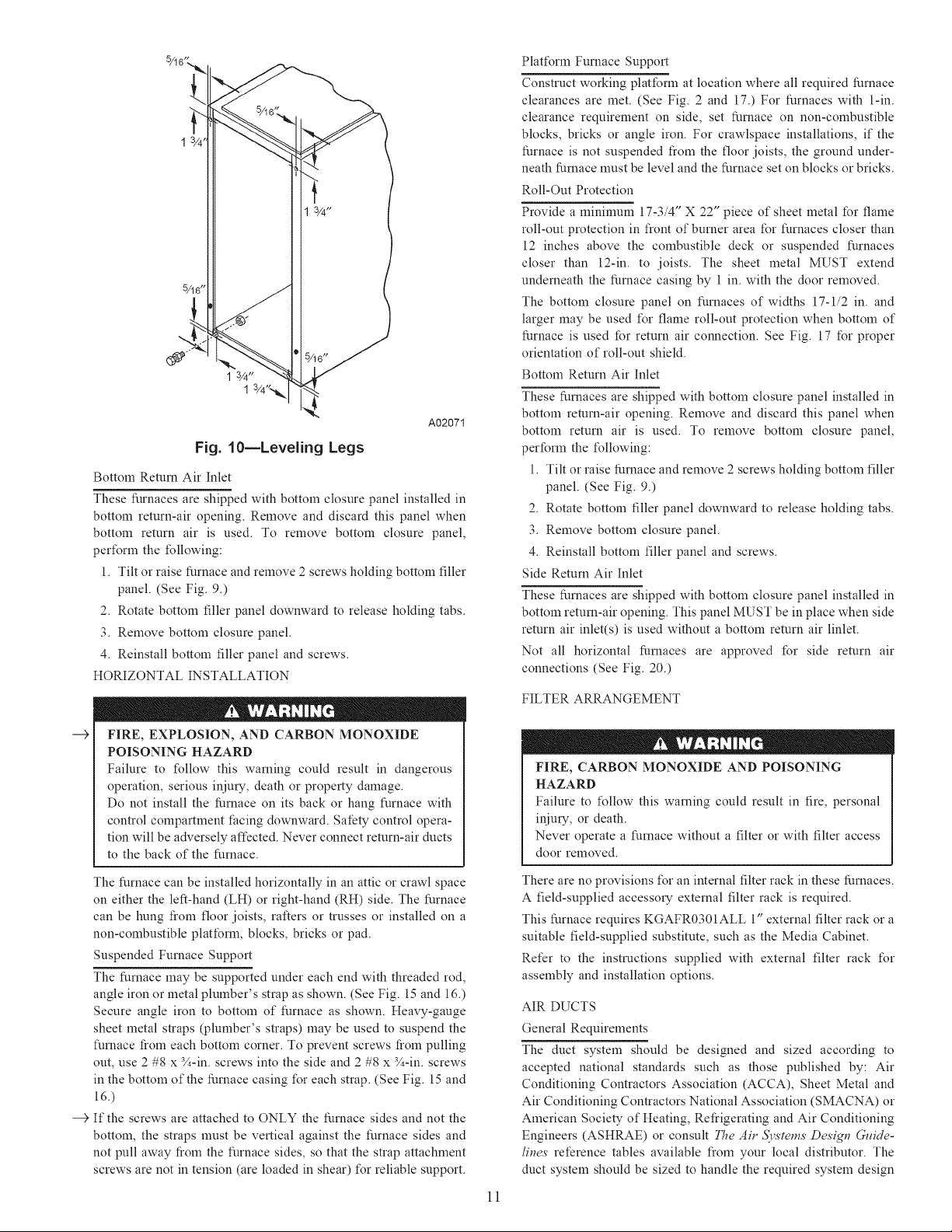
Leveling Legs (If Desired)
In upflow position with side return inlet(s), leveling legs may be
used. (See Fig. 10.) Install field-supplied, 5/16 X 1-1/2 in. (max)
corrosion-resistant machine bolts, washers and nuts.
NOTE: Bottom closure must be used when leveling legs are used.
It may be necessm T to remove and reinstall bottom closure panel
to install leveling legs. To remove bottom closure panel, see Item
1. in Bottom Return Air Inlet section.
To install leveling legs:
1. Position furnace on its back. Locate and drill a hole in each
bottom corner of furnace. (See Fig. 10.)
2. For each leg, install nut on bolt and then install bolt and nut in
hole. (Install flat washer if desired.)
3. Install another nut on other side of furnace base. (Install flat
washer if desired.)
4. Adjust outside nut to provide desired height, and tighten inside
nut to secure arrangement.
5. Reinstall bottom closure panel if removed.
DOWNFLOW INSTALLATION
NOTE: For downflow applications, this furnace is approved for
use on combustible flooring when any one of the t\_llowing 3
accessories are used:
, Special Base, KGASB
, Cased Coil Assembly Part No. CD5 or CK5
, Coil Box Part No. KCAKC
1. Determine application being installed from Table 3.
2. Construct hole in floor per Table 3 and Fig. 11.
3. Construct plenum to dimensions specified in Table 3 and Fig.
11.
4. Ifdownflow subbase, KGASB is used, install as shown in Fig.
12. If Coil Assembly Part No. CD5 or CK5 or Coil Box Part
No. KCAKC is used, install as shown in Fig. 13.
NOTE: It is recommended that the pert\_rated supply-air duct
flanges be completely folded over or removed from furnace when
installing the furnace on a factolT-supplied cased coil or coil box.
To remove the supply-air duct flange, use wide duct pliers or hand
seamers to bend flange back and t\_rth until it breaks off. Be careful
of sharp edges. (See Fig. 14.)
l0
A02098
1 3/4_
A02071
Fig. 10=Leveling Legs
Bottom Return Air Inlet
These furnaces are shipped with bottom closure panel installed in
bottom return-air opening. Remove and discard this panel when
bottom return air is used. To remove bottom closure panel,
pert\_rm the following:
1. Tilt or raise furnace and remove 2 screws holding bottom filler
panel. (See Fig. 9.)
2. Rotate bottom filler panel downward to release holding tabs.
3. Remove bottom closure panel.
4. Reinstall bottom filler panel and screws.
HORIZONTAL INSTALLATION
Platt\_rm Furnace Support
Construct working platform at location where all required furnace
clearances are met. (See Fig. 2 and 17.) For furnaces with 1-in.
clearance requirement on side, set furnace on non-combustible
blocks, bricks or angle iron. For crawlspace installations, if the
furnace is not suspended fiom the floor joists, the ground under-
neath furnace must be level and the furnace set on blocks or bricks.
Roll-Out Protection
Provide a minimum 17-3/4" X 22" piece of sheet metal for flame
roll-out protection in front of burner area for furnaces closer than
12 inches above the combustible deck or suspended furnaces
closer than 12-in. to joists. The sheet metal MUST extend
underneath the furnace casing by 1 in. with the door removed.
The bottom closure panel on furnaces of widths 17-1/2 in. and
larger may be used I\_r flame roll-out protection when bottom of
furnace is used for return air connection. See Fig. 17 for proper
orientation of roll-out shield.
Bottom Return Air Inlet
These furnaces are shipped with bottom closure panel installed in
bottom return-air opening. Remove and discard this panel when
bottom return air is used. To remove bottom closure panel,
perform the t\_llowing:
1. Tilt or raise furnace and remove 2 screws holding bottom filler
panel. (See Fig. 9.)
2. Rotate bottom filler panel downward to release holding tabs.
3. Remove bottom closure panel.
4. Reinstall bottom filler panel and screws.
Side Return Air Inlet
These furnaces are shipped with bottom closure panel installed in
bottom return-air opening. This panel MUST be in place when side
return air inlet(s) is used without a bottom return air linlet.
Not all horizontal furnaces are approved for side return air
connections (See Fig. 20.)
FILTER ARRANGEMENT
-__>
FIRE, EXPLOSION, AND CARBON MONOXIDE
POISONING HAZARD
Failure to t\_llow this warning could result in dangerous
operation, serious injm% death or property damage.
Do not install the furnace on its back or hang furnace with
control COlnpamnent facing downward. Safety control opera-
tion will be adversely affected. Never connect return-air ducts
to the back of the furnace.
The furnace can be installed horizontally in an attic or crawl space
on either the left-hand (LH) or right-hand (RH) side. The furnace
can be hung from floor joists, rafters or trusses or installed on a
non-combustible platform, blocks, bricks or pad.
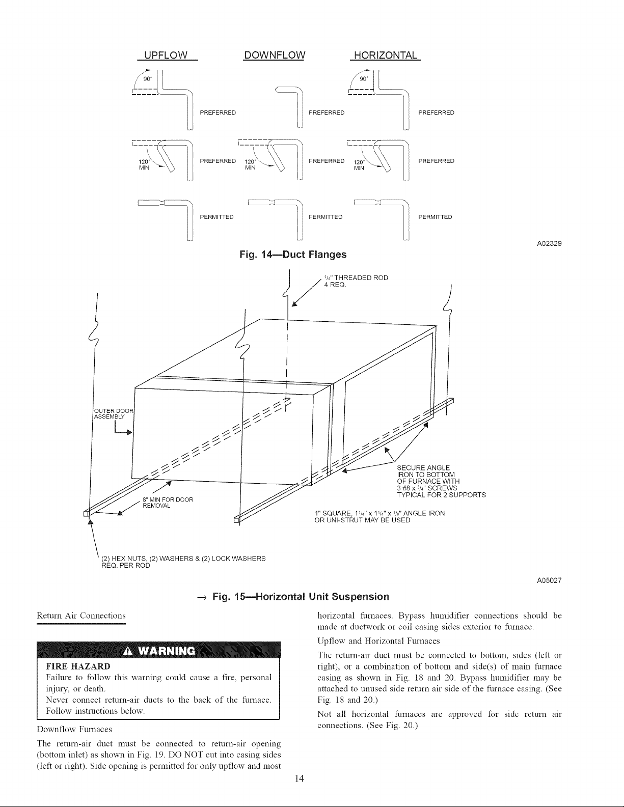
Suspended Furnace Support
The furnace may be supported under each end with threaded rod,
angle iron or metal plumber's strap as shown. (See Fig. 15 and 16.)
Secure angle iron to bottom of furnace as shown. Heavy-gauge
sheet metal straps (plumber's straps) may be used to suspend the
furnace from each bottom corner. To prevent screws from pulling
out, use 2 #8 x 3A-in. screws into the side and 2 #8 x 3A-in. screws
in the bottom of the furnace casing t\_r each strap. (See Fig. 15 and
16.)
---> If the screws are attached to ONLY the furnace sides and not the
bottom, the straps must be vertical against the furnace sides and
not pull away from the furnace sides, so that the strap attachment
screws are not in tension (are loaded in shear) l\_r reliable support.
FIRE, CARBON MONOXIDE AND POISONING
HAZARD
Failure to tMlow this warning could result in fire, personal
injuw, or death.
Never operate a furnace without a filter or with filter access
door removed.
There are no provisions t\_r an internal filter rack in these furnaces.
A field-supplied accessoi T external filter rack is required.
This furnace requires KGAFR0301ALL 1" external filter rack or a
suitable field-supplied substitute, such as the Media Cabinet.
Refer to the instructions supplied with external filter rack t\_r
assembly and installation options.
AIR DUCTS
General Requirements
The duct system should be designed and sized according to
accepted national standards such as those published by: Air
Conditioning Contractors Association (ACCA), Sheet Metal and
Air Conditioning Contractors National Association (SMACNA) or
American Society of Heating, Refrigerating and Air Conditioning
Engineers (ASHRAE) or consult The Air 51!,stems Design Guide-
lines reference tables available from your local distributor. The
duct system should be sized to handle the required system design
1!
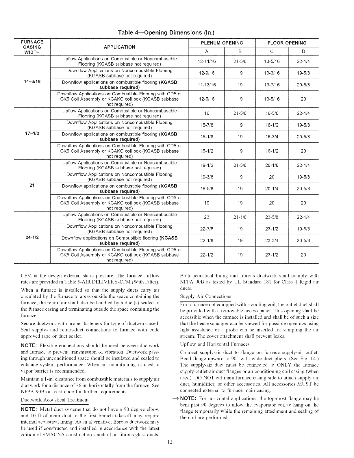
Table 4reOpening Dimensions (in.)
FURNACE
CASING
WIDTH
Upflow Applications on Combustible or Noncombustible 13-5/16
Flooring (KGASB subbase not required)
Downflow Applications on Noncombustible Flooring 13-3/16
14-3/16 Downflow applications on combustible flooring (KGASB 13-7/16
Downflow Applications on Combustible Flooring with CD5 or
CK5 Coil Assembly or KCAKC coil box (KGASB subbase 13-5/16
Upflow Applications on Combustible or Noncombustible 16-5/8 22-1/4
Flooring (KGASB subbase not required)
Downflow Applications on Noncombustible Flooring 16-1/2 19-5/8
17-1/2 Downflow applications on combustible flooring (KGASB 16-3/4 20-5/8
Downflow Applications on Combustible Flooring with CD5 or
CK5 Coil Assembly or KCAKC coil box (KGASB subbase 16-1/2 20
Upflow Applications on Combustible or Noncombustible
Flooring (KGASB subbase not required) 20-1/8 22-1/4
Downflow Applications on Noncombustible Flooring 20 19-5/8
21 Downflow applications on combustible flooring (KGASB 20-1/4 20-5/8
Downflow Applications on Combustible Flooring with CD5 or
CK5 Coil Assembly or KCAKC coil box (KGASB subbase 20 20
Upflow Applications on Combustible or Noncombustible
Flooring (KGASB subbase not required) 23-5/8 22-1/4
Downflow Applications on Noncombustible Flooring 23-1/2 19-5/8
24-1/2 Downflow applications on Combustible flooring (KGASB 23-3/4 20-5/8
Downflow Applications on Combustible Flooring with CD5 or
CK5 Coil Assembly or KCAKC coil box (KGASB subbase 23-1/2 20
APPLICATION
(KGASB subbase not required)
subbase required)
not required)
(KGASB subbase not required)
subbase required)
not required)
(KGASB subbase not required)
subbase required)
not required)
(KGASB subbase not required)
subbase required)
not required)
PLENUM OPENING
A B
12-11/16 21-5/8
12-9/16 19
11-13/16 19
12-5/16 19
16 21-5/8
15-7/8 19
15-1/8 19
15-1/2 19
19-1/2 21-5/8
19-3/8 19
18-5/8 19
19 19
23 21-1/8
22-7/8 19
22-1/8 19
22-1/2 19
FLOOR OPENING
C
D
22-1/4
19-5/8
20-5/8
2O
CFM at the design external static pressure. The furnace airflow
rates are provided in Table 5-AIR DELIVERY-CFM (With Filter).
When a furnace is installed so that the supply ducts can7 air
circulated by the furnace to areas outside the space containing the
furnace, the return air shall also be handled by a duct(s) sealed to
the furnace casing and terminating outside the space containing the
furnace.
Secure ductwork with proper t:asteners t\)r type of ductwork used.
Seal supply- and return-duct connections to furnace with code
approved tape or duct sealer.
NOTE: Flexible connections should be used between ductwork
and furnace to prevent transmission of vibration. Ductwork pass-
ing through unconditioned space should be insulated and sealed to
enhance system perfom_ance. When air conditioning is used, a
vapor barrier is recommended.
Maintain a 1-in. clearance from combustible materials to supply air
ductwork t\_ra distance of 36 in. horizontally tiom the furnace. See
NFPA 90B or local code t\_r further requirements.
Ductwork Acoustical Treatment
NOTE: Metal duct systems that do not have a 90 degree elbow
and 10 ft of main duct to the first branch take-off may require
internal acoustical lining. As an alternative, fibrous ductwork may
be used if constructed and installed in accordance with the latest
edition of SMACNA construction standard on fibrous glass ducts.
Both acoustical lining and fibrous ductwork shall comply with
NFPA 90B as tested by UL Standard 181 t\_r Class 1 Rigid air
ducts.
Supply Air Connections
For a furnace not equipped with a cooling coil, the outlet duct shall
be provided with a removable access panel. This opening shall be
accessible when the furnace is installed and shall be of such a size
that the heat exchanger can be viewed for possible openings using
light assistance or a probe can be inserted t\)r sampling the air
strealn. The cover attachment shall prevent leaks.
Upflow and Horizontal Furnaces
Connect supply-air duct to flange on furnace supply-air outlet.
Bend flange upward to 90 ° with wide duct pliers. (See Fig. 14.)
The supply-air duct must be connected to ONLY the furnace
supply-outlet-air duct flanges or air conditioning coil casing (when
used). DO NOT cut main furnace casing side to attach supply air
duct, humidifier, or other accessories. All accessories MUST be
connected external to furnace main casing.
--->
NOTE: For horizontal applications, the top-most flange may be
bent past 90 degrees to allow the evaporator coil to hang on the
flange temporarily while the remaining attachment and sealing of
the coil are performed.
]2
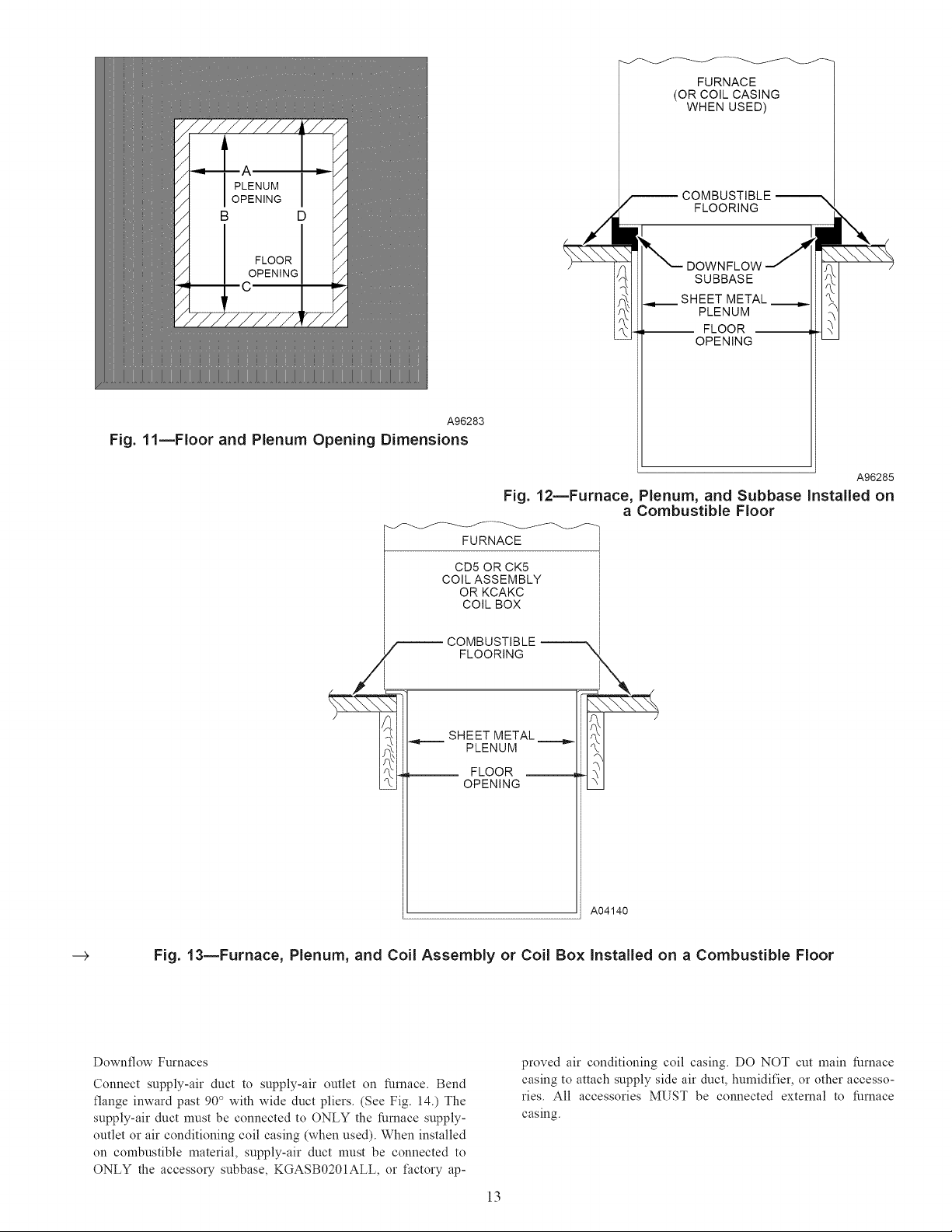
Fig. 11--Floor and Plenum Opening Dimensions
A96283
FURNACE
(OR COIL CASING
WHEN USED)
COMBUSTIBLE
FLOORING
DOWNFLOW
SUBBASE
SHEET METAL
PLENUM
-- FLOOR --
OPENING
A96285
Fig. 12mFurnace, Plenum, and Subbase installed on
a Combustible Floor
.-->
FURNACE
CD5 OR CK5
COiL ASSEMBLY
OR KCAKC
COiL BOX
_ COMBUSTIBLE
FLOORING ",
SHEET METAL
PLENUM
FLOOR
OPENING
X..-.../
A04140
Fig. 13mFurnace, Plenum, and Coil Assembly or Coil Box Installed on a Combustible Floor
Downflow Furnaces
Connect supply-air duct to supply-air outlet on furnace. Bend
flange inward past 90° with wide duct pliers. (See Fig. 14.) The
supply-air duct must be connected to ONLY the furnace supply-
outlet or air conditioning coil casing (when used). When installed
on combustible material, supply-air duct must be connected to
ONLY the accessol T subbase, KGASB0201ALL, or t:actory ap-
proved air conditioning coil casing. DO NOT cut main furnace
casing to attach supply side air duct, humidifier, or other accesso-
ries. All accessories MUST be connected external to furnace
casing.
13
UPFLOW
I _L
DOWNFLOW
HORIZONTAL
120_
MIN
PREFERRED
I
PREFERRED PREFERRED PREFERRED
PERMITTED PERMITTED PERMITTED
PREFERRED
PREFERRED
Fig. 14inDuct Flanges
V4"THREADED ROD
4 REQ.
I
I
I
I
I
A02329
J
SSEMBLY
L_.
8" MIN FOR DOOR
REMOVAL
(2) HEX NUTS, (2) WASHERS & (2) LOCK WASHERS
REQ. PER ROD
--> Fig. 15mHorizontal Unit Suspension
Return Air Connections
FIRE HAZARD
Failure to tMlow this warning could cause a fire, personal
injury , or death.
Never connect return-air ducts to the back of the furnace.
Follow instructions below.
Downflow Furnaces
The return-air duct must be connected to return-air opening
(bottom inlet) as shown in Fig. 19. DO NOT cut into casing sides
(left or right). Side opening is pem_itted t\_r only upflow and most
SECURE ANGLE
IRON TO BOTTOM
OF FURNACE WITH
3 #8 x 3/4" SCREWS
TYPICAL FOR 2 SUPPORTS
1" SQUARE, 1//4" x ll/4 '' x/Is" ANGLE IRON
OR UNI-STRUT MAY BE USED
horizontal furnaces. Bypass humidifier connections should be
made at ductwork or coil casing sides exterior to furnace.
Upflow and Horizontal Furnaces
The return-air duct must be connected to bottom, sides (left or
right), or a combination of bottom and side(s) of main furnace
casing as shown in Fig. 18 and 20. Bypass humidifier may be
attached to unused side return air side of the furnace casing. (See
Fig. 18 and 20.)
Not all horizontal furnaces are approved t1_r side return air
connections. (See Fig. 20.)
14
A05027
 Loading...