


31MF
Installation and Operating Instructions
NOTE: Read the entire instruction before starting the installation.
SAFETY CONSIDERATIONS
Installation and service of heating and air conditioning equipment
can be hazardous due to system pressure and gas and electrical
components. Only trained and qualified personnel should install,
repair or service heating and air conditioning equipment.
Untrained personnel can perform basic maintenance functions
such as cleaning and replacingair filters. All other operations must
be performed by trained service personnel. When working on
heating and air conditioning equipment, observe precautions in the
literature, tags, and labels attached to or shipped with the unit and
other safety precautions that may apply.
Follow all safety codes. Wear safety glasses and work gloves.
Read these instructions thoroughly and follow all warnings or
cautions attached to the unit. Consult local building codes for
special installation requirements.
Recognize safety information. This is the safety-alert symbol
When you see this symbol on the unit or in instructions and
manuals, be alert to the potential for personal injury.
Understand the signal word—DANGER, WARNING, or CAUTION. These words are used with the safety-alert symbol. DANGER identifies the most serious hazards which will result in severe
personal injury or death. WARNING signifies hazards that could
result in personal injury or death. CAUTION is used to identify
unsafe practices, which would result in minor personal injury or
product and property damage.
INTRODUCTION
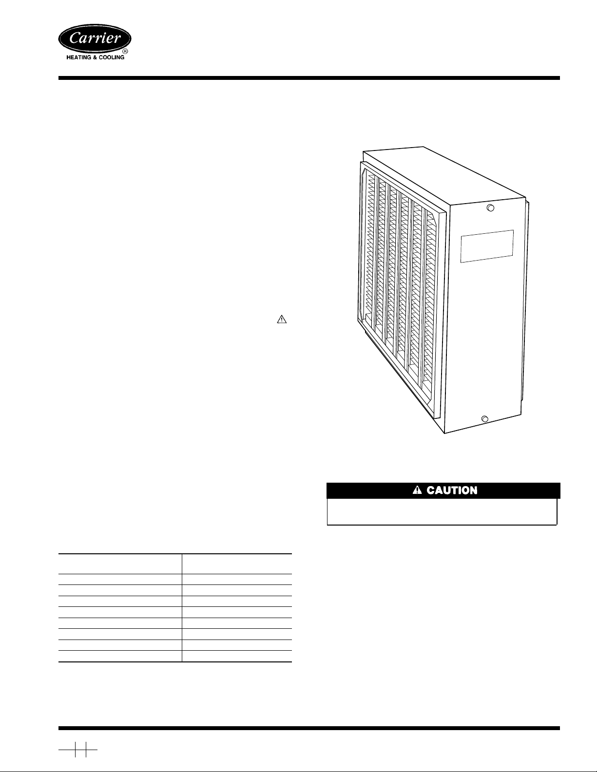
The Model 31MF High-Efficiency Mechanical Air Cleaner is
designed for installation in the return-air duct of any forced-air
heating and/or cooling system. It is designed for use in systems
with airflow up to 2000 cfm. For higher airflows, additional units
may be required.
The Model 31MF is a mechanical air cleaner incorporating 78 sq
ft of glass microfiber filter media to clean the air circulated
through it with a low pressure drop. (See Table 1.)
Table 1—Air Cleaner Resistance
RESISTANCE
(IN. WC)
.03 600
.05 800
.07 1000
.10 1200
.13 1400
.16 1600
.20 1800
.24 2000
AIRFLOW
(CFM)
31MF
Mechanical Air Cleaner
.
Fig. 1—Model 31MF Mechanical Air Cleaner
INSTALLATION
Step 1—Install Air Cleaner Cabinet in Return-air System
Turn OFF the electrical supply to the furnace before beginning installation.
1. Remove and discard existing furnace filter(s).
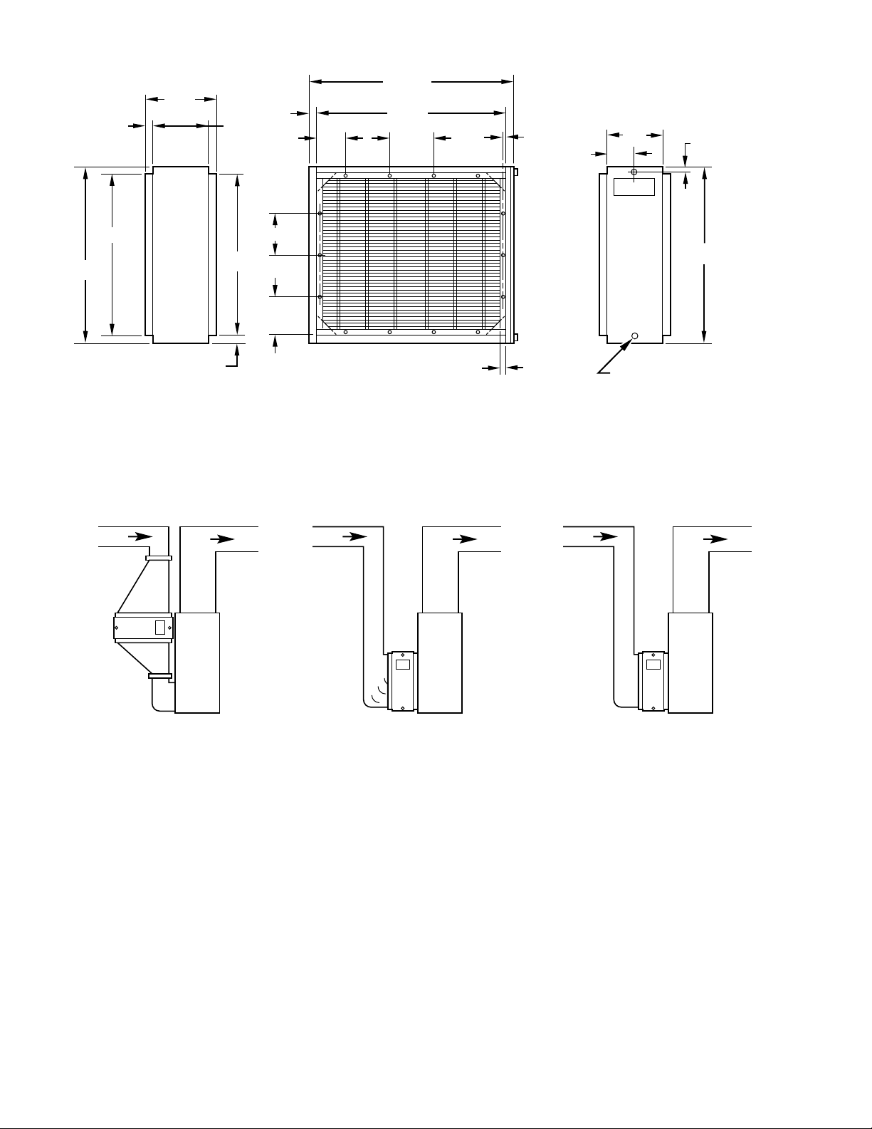
2. Referring to Fig. 2 and 3 for air cleaner dimensions and typical
installations, determine best installation location of air cleaner.
NOTE: A 26-in. clearance must be allowed for removal of the
media frame assembly from the air cleaner cabinet.
3. Using standard practices, remove a section of return-air duct
to allow installation of air cleaner cabinet.
4. Install air cleaner in duct opening, providing an airtight seal to
duct with necessary materials.
NOTE: For systems with a right side return-air duct, rotate the air
cleaner 180° for proper installation. Remove and reinstall the front
access panel in an upright position. (See Fig. 3 for typical
installations.)
A90321
Manufacturer reserves the right to discontinue, or change at any time, specifications or designs without notice and without incurring obligations.
Book 1 4
Tab 7a 9a
PC 101 Catalog No. 533-132 Printed in U.S.A. Form 31MF-2SI Pg 1 12-91 Replaces: 31MF-1SI
11
25
⁄16″
1
9
⁄4″
13
⁄16″
7
1
1
⁄8″
3
⁄4″
3
3
⁄16″ 5 5⁄8″
23
5
⁄16″
5
⁄16″
7
7
⁄8″
15
3
⁄16″
1
⁄2″
13
19
7
21
⁄16″
AIR FLOW
⁄16″
6″
1
21
13
19
⁄16″
15
3
⁄16″
13
⁄16″
1
⁄2″
KNURLED THUMBSCREW
WITH .130 IN. DIA STARTER
POINT.
Fig. 2—Dimensional Drawing
AIR FLOW AIR FLOW
⁄2″
A90295
FURNACE WITH
TRANSITION
FURNACE WITH
TURNING VANES
Fig. 3—Typical Installations (Upflow Furnaces)
Step 2—Install Air Cleaner Filter Gage
Blower suction will create a slight vacuum so air will flow into the
bottom of the filter gage and through its chamber—lifting the ball
in the gage. As the filter media in the air cleaner becomes dirty, the
increase in vacuum and resulting airflow will lift the ball proportionally. When the ball reaches the top arrow, the air cleaner media
should be replaced.
The air cleaner filter gage should be installed in a convenient
location on a vertical duct surface between the air cleaner and the
furnace blower or in the furnace casing of the blower compartment.
1. Drill a 3/8-in. hole in duct work or casing. Place spring gage
holder in hole. (See Fig. 4.)
2. Insert gage mounting stud through hole in condition indicator
card and then in spring gage holder so stud projects into duct
or casing. (See Fig. 4.)
FURNACE NO
TRANSITION
A90294
3. Adjust airflow gage by rotating range adjustment plug until
ball hovers at tip of lower arrow. (See Fig. 4.)
When the air cleaner media begins to become clogged and dirty,
the ball will move up the gage. When the ball is in the red range
(shown on the condition indicator card), the air cleaner should be
serviced.
Step 3—Install Filter Media in Air Cleaner Cabinet
NOTE: These instructions should also be followed when the filter
gage indicates the filter media needs to be changed.
1. Loosen two thumb screws on front access panel and remove
panel. Slide filter media frame assembly from air cleaner
cabinet.
2. Remove filter media from carton. Ensure there are no holes or
tears in filter media.
2
 Loading...