


SERVICE
MANUAL
REVISION 0
AUG. 2001
COPYRIGHT
2001 CONON INC. CANON LBP-2000 REV.0 AUG.2001
FY8-13HQ-000

COPYRIGHT © 2001 CANON INC
Use of this manual should
be strictly supervised to
avoid disclosure of confidential information.

PREFACE
INTRODUCTION
This Service Manual provides basic facts and figures needed to service the laser beam printer LBP2000 (hereafter, the Printer), performed to ensure initial product quality and performance.
The following options may be used in combination with the Printer:
• Universal Cassette UC-65
• Paper Feeder Unit PF-65
• Hard Disk HD-65
• Ether Board EB-65
This Service Manual also covers these options. For others, see their respective Service Manuals.
This Service Manual consists of the following chapters:
Chapter 1, ‘Product Outline,’ introduces features and specifications as well as how to install and
use the Printer.
Chapter 2, ‘Operation,’ explains the principles of operation used in the mechanical/electrical
systems of the Printer according to function as well as timing at which associated
mechanisms operate.
Chapter 3, ‘Mechanical System,’ shows the mechanical construction of the Printer and how to
disassemble/assemble and adjust its components.
Chapter 4, ‘Troubleshooting,’ indicates how to correct various faults and make checks/adjust-
ments, and provides standards to follow.
APPENDIX contains a general timing chart, general circuit diagrams, and list of signals.
Changes made to the descriptions because of product improvement or the like will be commu-
nicated in the form of Service Information bulletins as they occur.
All service persons are expected to go through this Service Manual and Service Information
bulletins for a full understanding of the Printer while equipping themselves with skills and knowledge used to identify and correct faults in the Printer.
P - 1

PREFACE
CONTENTS
CHAPTER 1 PRODUCT OUTLINE
I. FEATURES.......................................... 1 -1
II. SPECIFICATIONS ............................. 1- 2
A. Printer ........................................ 1 -2
B. Options....................................... 1 -4
III. SAFETY ................................................ 1 -5
A. Safety of the Laser Unit ...... 1- 5
B. Safety of Toner ....................... 1 -5
C. Safety of Ozone ...................... 1 -5
IV. NAMES OF PARTS........................... 1 -6
A. External View .......................... 1- 6
B. Cross Section........................... 1 - 8
V. INSTALLATION.................................. 1 -9
CHAPTER 2 OUTLINE OF OPERATION
I. BASIC OPERATION ......................... 2 -1
A. Functional Construction .... 2 -1
B. Sequence of Basic
Operation .................................. 2 - 2
C. Power-On Sequence .............. 2 -6
II. ENGINE CONTROL SYSTEM ....... 2 - 7
A. Outline of the Electrical
Circuitry .................................... 2- 7
B. Inputs to and Outputs from
the DC Controller .................. 2 -9
C. Controlling the Fixing
Mechanisms ............................. 2-12
D. High-Voltage Power Supply
Circuit ........................................ 2-18
E. Low-Voltage Power Supply
Circuit ........................................ 2-23
F. Video Interface Control ...... 2-25
G. Other Control .......................... 2-27
III. LASER/SCANNER SYSTEM ......... 2-30
A. Outline ....................................... 2-30
B. Laser Control Circuit ........... 2-31
C. Scanner System...................... 2-34
IV. IMAGE FORMATION SYSTEM .... 2-37
A. Outline ....................................... 2-37
A. Points to Note About
Installation............................... 1 -9
B. Selecting the Site .................. 1 -9
C. Unpacking and Installing ... 1-11
D. When Storing or Handling
the EP-65 Cartridge.............. 1-18
VI. RELOCATING THE PRINTER ...... 1-21
VII. ROUTINE MAINTENANCE/
INSPECTION BY THE USER ........ 1-22
VIII.USING THE PRINTER ..................... 1-25
A. The Operation Panel............. 1-25
B. Operation Panel Menus ....... 1-27
C. Service Menu ........................... 1-28
B. Printing Process ..................... 2-38
V. PICKUP/FEEDING SYSTEM ........ 2-46
A. Outline ....................................... 2-46
B. Detecting the Paper Size.... 2-49
C. Using the Cassette ................ 2-50
D. Using the Multifeeder .......... 2-51
E. Fixing/Delivery
Assembly ................................... 2-53
F. Detecting Jams....................... 2-54
VI. VIDEO CONTROL SYSTEM .......... 2-59
A. Outline of the Electrical
Circuitry .................................... 2-59
B. Operation Panel...................... 2-62
C. Self Test..................................... 2-63
VII. PAPER FEEDER ............................... 2-65
A. Outline ....................................... 2-65
B. Inputs to and Outputs from
the Paper Feeder
Controller.................................. 2-66
C. Pickup/Feeding
Operation .................................. 2-67
D. Detecting Jams....................... 2-70
P - 2

CHAPTER 3 MECHANICAL SYSTEM
PREFACE
I. EXTERNALS AND CONTROLS .... 3 - 1
A. External Covers ...................... 3 -1
B. Heat Discharging Fan .......... 3 - 4
C. Door Switch Assembly ......... 3- 5
II. PCBS ..................................................... 3- 8
A. Arrangement of the PCBs... 3 -8
B. Video Controller PCB ........... 3- 8
C. DC Controller PCB ................. 3-12
D. Power Supply PCB
Ass embl y ................................... 3-14
III. DRIVE MECHANISMS .................... 3-15
A. Main Motor ............................... 3-15
B. Drive Assembly ....................... 3-16
IV. FEEDING MECHANISMS............... 3-17
A. Cassette Pickup
Ass embl y ................................... 3-17
CHAPTER 4 TROUBLESHOOTING
I. INTRODUCTION ............................... 4 -1
A. Troubleshooting Flow
Chart ........................................... 4 - 1
B. Making Initial Checks.......... 4 -4
C. Test Print .................................. 4 -5
II. TROUBLESHOOTING IMAGE
FAULTS ................................................ 4-10
III. MEASURES AGAINST JAMS ....... 4-17
IV. FEEDING FAULTS............................ 4-21
V. MALFUNCTIONS............................... 4-23
VI. CORRECTING A FAULT STATUS
CONDITION ........................................ 4-25
VII. STANDARDS AND
ADJUSTMENTS................................. 4-31
A. Making Mechanical
Adjustments............................. 4-31
B. Making Electrical
Adjustments............................. 4-32
C. Copying the Counter
Readings.................................... 4-33
D. Variable Resistors (VR), Light-
Emitting Diodes (LED), Check
Pins, Jumpers, and Switches by
PCB .............................................. 4-34
B. Multifeeder Tray Pickup
Ass embl y ................................... 3-20
C. Registration Roller
Ass embl y ................................... 3-23
V. EXPOSURE MECHANISMS........... 3-25
A. Laser/Scanner Assembly .... 3-25
VI. CHARGING/DEVELOPING/
CLEANING MECHANISMS ............ 3-26
A. EP-65 Cartridge ...................... 3-26
B. Transfer Charging Roller.... 3-26
VII. FIXING SYSTEM............................... 3-27
A. Fixing Assembly ..................... 3-27
VIII.PAPER FEEDER ............................... 3-34
A. External Covers ...................... 3-34
B. Pickup Assembly .................... 3-34
C. Drive Mechanism ................... 3-38
D. PCBs ............................................ 3-39
VIII.MAINTENANCE AND
INSPECTION ...................................... 4-38
A. Periodically Replaced
Parts ............................................ 4-38
B. Durables ..................................... 4-38
C. Scheduled Servicing ............. 4-39
D. Points to Note for
Cleaning..................................... 4-40
E. Standard Tools........................ 4-41
F. Special Tools............................ 4-42
G. Solvents and Oils ................... 4-42
IX. ARRANGEMENT OF ELECTRICAL
PARTS .................................................. 4-43
A. Switches and Sensors .......... 4-43
B. Clutches, Solenoids, and
Motors ........................................ 4-45
C. Others......................................... 4-47
D. PCBs ............................................ 4-48
E. Connectors ............................... 4-50
APPENDIX
I. GENERAL TIMING CHART ........... A - 1
II. GENERAL CIRCUIT DIAGRAM ... A-3
III. LIST OF SIGNALS ............................ A-5
A. Inputs to and Outputs from
the DC Controller PCB......... A- 5
B. Inputs to and Outputs from
the Paper Feeder
Controller PCB ........................ A-9
IV. MESSAGES TABLE .......................... A-1 0
P - 3

CHAPTER 1
PRODUCT OUTLINE
I. FEATURES.......................................... 1 -1
II. SPECIFICATIONS ............................. 1 -2
III. SAFETY ................................................ 1 -5
IV. NAMES OF PARTS ........................... 1 - 6
V. INSTALLATION.................................. 1 -9
VI. RELOCATING THE PRINTER ...... 1-21
VII. ROUTINE MAINTENANCE/
INSPECTION BY THE USER ........ 1-22
VIII.USING THE PRINTER ..................... 1-25

CHAPTER 1
I. FEATURES
1 . High-speed printing
Although compact in design, the Printer is a high-speed printer capable of generating 20 pages per
minute.
2 . Various sources of paper with the addition of options
In addition to the cassette and the multifeeder that come as standard, the Printer may be combined with three 250-sheet paper feeders (PF-65; hereafter, paper feeder) to enable 5-way pickup,
each source with different types of paper.
3 . Continuous printing of large volumes of work
As many as three option paper feeders may be installed to the Printer. Combined with the standard cassette and multifeeder, a maximum of about 1,100 sheets of paper (64 g/m
modated for continuous, large-volume printing work.
4 . Power saving, toner saving design
The printer is designed to enter sleep mode (power saving mode) after remaining in standby mode
for a specific period of time, thereupon automatically cutting the power to the fixing heater and
ultimately limiting the total consumption of power.
The printer is also able to print in toner save mode, in which it prints using less toner (lighter
output) to save on toner.
2
) may be accom-
5 . Auto interface switching mechanism
In addition to the parallel interface (Centronics compatible) and USB (V1.0 slave only) that come
as standard, the printer allows the connection of a build-in print server (option; 10Base-T/100BaseTX). Depending on which interface board to use, the Printer will automatically switch among
parallel, USB, and Ethernet (option) interfaces.
6 . Auto emulation switching
This printer supports the Hewlett-Packard’fs PCL5e and PCL-XL printer language. Also, Adobe
PostScript 3 can be provided by installing the optional Canon Adobe PostScript 3 Module A-65.
This enables auto emulation switching for PCL and PostScript based on the received data.
1 - 1

CHAPTER 1
II. SPECIFICATIONS
A. Printer
1 . Printer engine
1) Type Desktop page printer
2) Printing method Electrophotostatic
3) Printing speed (Note 1) 20 pages/min (A4, horizontal), 11 pages/ min (A3)
4) First print time (Note 2) 11.0 sec (approx.; A4, horizontal)
5) Wait time (Note 3) 30 sec or less
6) Resolution
Main scanning direction 600 dpi
Sub scanning direction 600 dpi
7) Image formation system
Laser Semiconductor laser
Scanning method 6-face mirror
Photosensitive drum OPC (30-mm dia.)
Charging Roller charging
Exposure Laser scanning
Toner Magnetic, 1-component, dry
Development 1-component toner projection
Toner supply Cartridge replacement
(EP-65; good for about 10,000 A4 pages, dot ratio at 4% and print
ratio at 5%)
Transfer Roller transfer
Separation Curvature separation
Cleaning Rubber blade
Fixing Heat roller fixing
8) Pickup Multifeeder tray
Cassette
Paper feeder (option)
Paper type Plain paper, thick paper, colored paper, label sheet, recycled paper,
transparency film, envelopes
Paper size
Multifeeder tray Plain paper (64 g/m
2
to 157 g/m2, recommended) or label sheets of following dimen-
g/m
sions: 76.2 (W) x 98 (L) to 297 (W) x 431.8 (L) mm
Cassette Plain paper (64 g/m
B3, B4, A4, A4R (vertical), B5, A5, 11 x 17, LGL, LTR, Executive;
label sheets
Stack multifeeder 10 mm high (about 100 sheets of 64 g/m
Cassette 25 mm deep (about 250 sheets of 64 g/m
Cassette type Universal cassette designed for following: A3, B4, A4, A4R (vertical),
B5, A5, 11 x 17, LGL, LTR, Executive
9) Delivery Face-down (250 sheets max. of 64 g/m
10) Operating environment
Temperature 7.5 to 32.5ºC (45.5 to 90.5ºF)
Humidity 5% to 90% RH
Atmospheric pressure 746 to 1013 hPa (560 to 760 mmHg)
11) Power consumption Sleep mode: 16 W (avr)
(at 20ºC room temp, In standby: 118 W (avr)
at rated supply voltage) In printing: 448 W (avr)
Maximum: 850 W or less
2
to 90 g/m2, recommended) or thick paper (91
2
to 90 g/m2, recommended) of following sizes:
2
paper)
2
paper)
2
paper)
1 - 2

CHAPTER 1
12) Noise (published noise Sound power level 67 dB or less (printing)
by ISO9296) 57 dB or less (standby)
Sound pressure level 53 dB or less (printing)
(bystander position) 38 dB or less (standby)
13) Dimensions 488 (W) x 455 (D) x 311 (H) mm/18.9 (W) x 17.7 (D) x 12.2 (H) in. (w/
o options)
14) Weight 15 kg/33 lb (approx.; including 250-sheet cassette), 2 kg/4 lb
(approx.; cartridge)
15) Power supply 120 to 127 V, 220 to 240 V 50/60 Hz
16) Options Paper Feeder Unit PF-65 (3 units max.)
Universal Cassette UC-65
Hard Disk HD-65
Ether Board EB-65
Notes: 1 . Based on test prints made at 20ºC room temperature with the rated supply voltage.
May be longer depending on the type of paper and the fixing mode selected.
2. Time required (room temperature at 20ºC and printer in standby) from when the print
signal arrives form the video controller to when a single A4 sheet is received and delivered to the delivery tray. May be longer depending on the type of paper and the fixing
mode selected.
3. At 20ºC room temperature, without an expansion RAM.
The above specifications are subject to change for product improvements.
2 . Video Controller
1) CPU Power PC 405 (200 MHz)
2) Memory (RAM) 8 MB (built-in; may be expanded to 72 MB max. with option)
3) Memory (ROM) 8 MB (build-in; may be expanded to 16 MB max. with option)
4) RAM slot 1
5) ROM slot 3
6) Host interface
Standard • Centronics (IEEE1284 compatible)
• USB (V1.0 slave only)
Option • 10Base-T/100Base-TX
7) Translator
Standard PCL5e, PCL-XL
Option Adobe PostScript Level 3 Module A-65
8) Resident font 45 scalable fonts (MicroType fonts), 32 TrueType fonts, 9 Bitmap
fonts
9) Optional font 136 fonts for A-65 module
10) Scaler UFST
11) Option Flash ROM Module FR-65 (4MB: for fonts and macros storage)
The above specifications are subject to change for product improvements.
1 - 3

CHAPTER 1
B. Options
1 . Built-in print server
a. Hardware
1) Interface 10Base-T, 100Base-TX
2) CPU AXIS: EXTRAX100LX (32-bit RISC CPU 100 MHz)
3) ROM 2 MB
4) RAM 4 MB
5) Dimensions 100 (W) x 85.5 (D) x 24 (H) mm/3.9 (W) x 3.1 (D) x 0.8 (H) in.
6) Weight 100 g/0.2 lb (approx.)
7) Power supply 3.3 VDC (from printer)
b. Software
1) Protocol IPX/SPX, TCP/IP, AppleTalk (EtherTalk), NetBEUI/NetBIOS
2) Frame type IPX/SPX : 802.2, 802.3, Ethernet II, 802.2 Snap
TCP/IP : Ethernet II
AppleTalk : 802.2 SNAP (Phase II)
NetBEUI/NetBIOS : 802.2
5) Print application IPX/SPX : Bindery Server, NDS PServer, NPritner, RPrinter
TCP/IP : LPD, FTP, RAW, IPP
AppleTalk : CAP (Canon AppleTalk PrintServer)
The above specifications are subject to change for product improvements.
2 . Paper feeder
1) Pickup paper size A3, B4, A4, A4R (vertical), B5, A5, 11 x 17, LGL, LTR, Executive
(plain paper; 64 g/m
2) Cassette size 25 mm deep (about 250 sheets of 64 g/m2 paper)
3) Cassette type Universal (may be configured for following: A3, B4, A4, A4R (vertical), B5, A5, 11 x 17, LGL, LTR, Executive
4) Dimensions 488 (W) x 406 (D) x 118 (H) mm/18.9 (W) x 15.7 (D) x 4.7 (H) in.
5) Weight 5 kg/11 lb (approx., including cassette)
6) Power supply 24 VDC, 5 VDC (from printer)
The above specifications are subject to change for product improvement.
3 . Hard disk
1) Memory 10 GB
2) Interface ATA-3
3) Dimensions 112 (W) x 136 (D) x 28 (H) mm/4.3 (W) x 5.1 (D) x 1.1 (H) in.
4) Power supply 5 VDC (from printer)
The above specifications are subject to change for product improvements.
2
to 90 g/m2, recommended)
1 - 4
CHAPTER 1
III. SAFETY
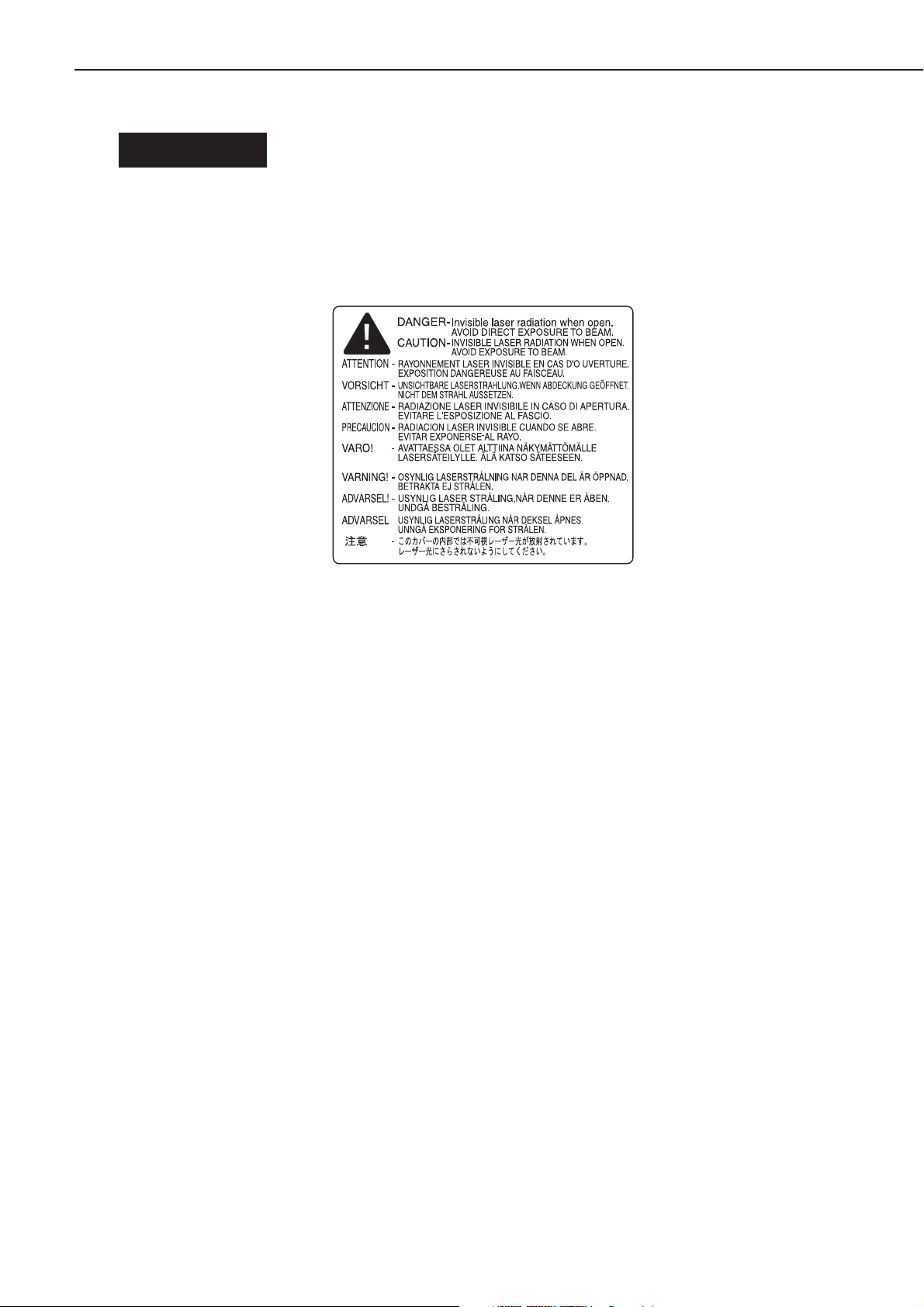
A. Safety of the Laser Unit
Although invisible, laser light is used inside the laser/scanner unit. Do not disassemble the laser/
scanner unit, as exposure to laser light can damage your eyes.
The Printer’s laser/scanner unit is not designed for adjustment in the filed. The following shows
the label attached to the cover of the laser/scanner unit.
Figure 1-3-1
B. Safety of Toner
Toner is a non-toxic material composed of plastic and small amounts of colorings. If your skin or
clothes came into contact with toner, remove as much of it as possible using dry tissues; then,
rinse with cold water. (Do not use warm water. The toner will turn into jelly, and will not come off.)
Do not bring toner into contact with vinyl material. They tend to react with each other.
C. Safety of Ozone
The Printer’s charging roller generates a minute amount of ozone gas (O
discharge (only when the Printer is in operation).
The Underwriters’ Laboratory (UL) provides standards for amounts of ozone discharge, and the
Printer is verified to satisfy the requirements at time of shipment from the factory.
3
) because of corona
1 - 5
CHAPTER 1
IV. NAMES OF PARTS
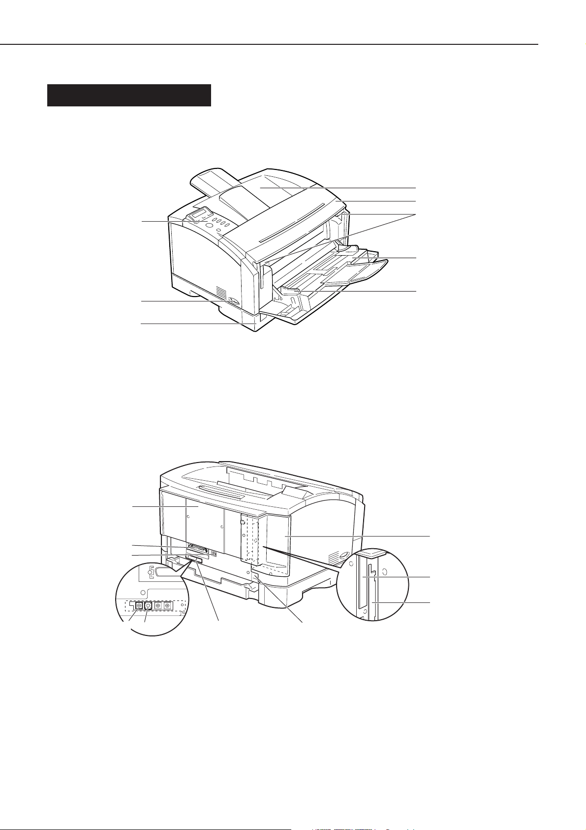
A. External View
1 . Printer engine
• Front of the printer
[8]
[1]
[2]
[3]
[4]
[7]
[6]
1: Delivery tray
2: Front cover
3: Open/close lever
4: Multifeeder tray
• Rear of the printer
[10]
[9]
[8]
[5]
Figure 1-4-1
5: Paper guide
6: Cassette
7: Power supply switch
8: Control panel
[1]
[7]
[6]
1: Expansion board slot cover
2: Expansion board slot 1
3: Expansion board slot 2
4: Power receptacle
5: Test Print switch
1 - 6
[5]
[2]
[3]
[4]
Figure 1-4-2
6: Test Print switch
7: Leading edge margin adjusting volume
(VR101)
8: USB interface connector
9: Parallel interface connector
10: Slot cover
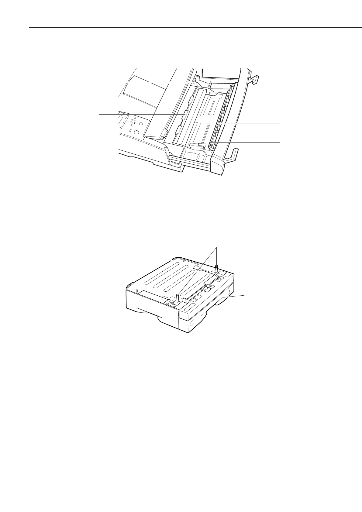
• Behind the front cover
[4]
[3]
CHAPTER 1
[1]
[2]
Figure 1-4-3
1: Static eliminating brush
2: Transfer charging roller
2 . Paper feeder
1: Connector
2: Positioning pin
3: Toner cartridge guide
4: Registration roller
[1]
Figure 1-4-4
3: Cassette
[2]
[3]
1 - 7
CHAPTER 1
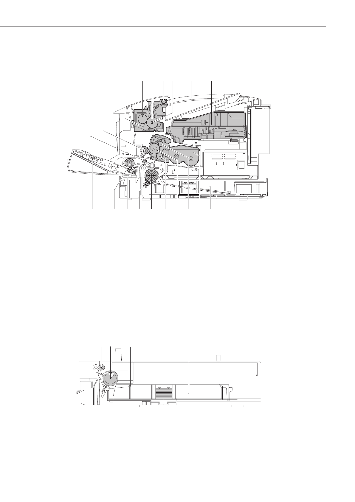
B. Cross Section
1 . Printer engine
[4][3][2][1] [5] [6] [7] [9][8]
1: Registration roller
2: Transfer charging roller
3: Fixing assembly
4: Pressure roller
5: Fixing roller
6: Delivery roller
7: Fixing heater
8: Control panel
9: Laser/scanner unit
10: Cassette
2 . Paper feeder
[1]
[2]
[12][13][14]
Figure 1-4-5
11: Cartridge
12: Primary charging roller
13: Photosensitive drum
14: Developing cylinder
15: Cassette pickup roller
16: Cassette separation pad
17: Manual feed separation pad
18: Manual feed pickup roller
19: Multifeeder tray
[3] [4]
[11] [10][19] [15][17] [16][18]
1: Feeding roller
2: Cassette pickup roller
1 - 8
Figure 1-4-6
3: Cassette separation pad
4: Cassette

CHAPTER 1
V. INSTALLATION
A. Points to Note About Installation
The Printer is thoroughly adjusted and inspected at the factory before it is packed and shipped.
Installation work is important in that the Printer must perform in the field as it did when it passed
the factory inspection.
The service engineer must have a full understanding of the machine, and install it in an appro-
priate site using specific steps, following up the work with a thorough inspection.
B. Selecting the Site
The site of installation must meet the following requirements; if possible, visit the site of installation before the Printer is delivered.
1 . Power supply
The power supply must satisfy the following:
• AC: ±10% of ratings
• Frequency: 50/60 ±2 Hz
2 . Operating environment
The site must satisfy the following:
• Its floor must be level.
• Its temperature and humidity are as follows:
Ambient temperature: 7.5ºC to 32.5ºC (45.5 to 90.5ºF)
Ambient humidity: 5% to 90% RH (There must not be condensation.)
• It must be well ventilated, without accumulation of heat.
Avoid the following areas:
• subject to direct rays of the sun; as necessary, provide thick curtains to block out the sun.
• subject to magnetism (magnet, magnetic filed).
• subject to vibration.
• subject to dust.
• near a source of fire or water.
1 - 9
CHAPTER 1
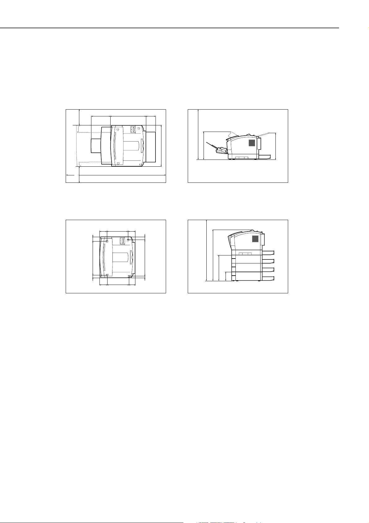
3 . Spatial requirements
Allow an appropriate distance from all walls, thus ensuring unobstructed work space. (Figure 1-5-
1) If the Printer is to be installed on a table, be sure that the table is wide enough to accommodate
the Printer’s feet (rubber pads) and strong enough to withstand the Printer’s weight.
Dimensions Around
the Printer (standard)
100
200
1300
Locations of the Feet
260
90 84
408 5131
27790
View from the Side (standard)
434249
123
(mm)
488
440
338
325
(mm)
View form the side
(with 3 paper feeders)
720
620
312
106
(mm)
67
436
16 36
(mm)
(Each rubber foot is
5 mm in height, and its tip is
a square of 18 x 18 mm.)
Figure 1-5-1
1 - 10

CHAPTER 1
C. Unpacking and Installing
When a piece of metal is brought in from a cold to warm place, droplets of water can develop on its
surface. This phenomenon is known as condensation, and the use of an LBP suffering from condensation can cause various printing faults.
If the Printer has been brought in from a cold place, leave it alone for at least one hour before
unpacking it.
1 . Unpacking the printer
1) Unpack the Printer.
2) Check to make sure that none of the following is missing:
1. power cord
2. toner cartridge
3. dust cover
4. CD-ROM
5. documentation
3) Remove the plastic bag used to cover the Printer, and check to make sure that the covers and
the like are free of image and deformation from transportation.
4) Slide out the cassette, and move the Printer to the site of installation.
5) Place the Printer at the site of installation. (Take care.)
• If the Printer is to be laid on a paper feeder, be sure that the position pins on the paper feeder
fit into the openings in the Printer’s bottom.
6) Remove the tape used to keep the parts in place.
7) Open the multifeeder tray, and pull the open/close lever to the front to slide out the front
cover.
8) Remove the protective tape used to keep the transfer charging roller in place.
9) Lock the open/close lever, and close the front cover and the multifeeder tray.
10) Slide in the cassette.
2 . Unpacking and installing the cartridge
1) Open the bag used to pack the cartridge, and take out the cartridge.
2) Holding the cartridge as shown in Figure 1-5-13, shake it gently up and down about 5 to 6
times so that the toner inside it will be even.
3) Place the cartridge on a level surface. While holding the top of the cartridge with one hand, pull
the tab carefully with the other hand; then, pull straight out the sealing tape.
4) Open the multifeeder tray, and pull the open/close lever to the front to draw out the front
cover.
5) Holding the cartridge with both hands, fit it in the Printer. At this time, be sure to slide in the
cartridge carefully until it butts against the rear of the Printer.
1 - 11
CHAPTER 1
3 . Unpacking and installing the hard disk
Note: Before handling the hard disk, be sure to touch a metal area of the Printer to avoid dam-
aging the PCBs by static charges.
1) Turn off the Printer, and disconnect the power cord and the interface cable.
2) Take out the hard disk from its packaging box.
3) Remove the vinyl bag used to cover the hard disk.
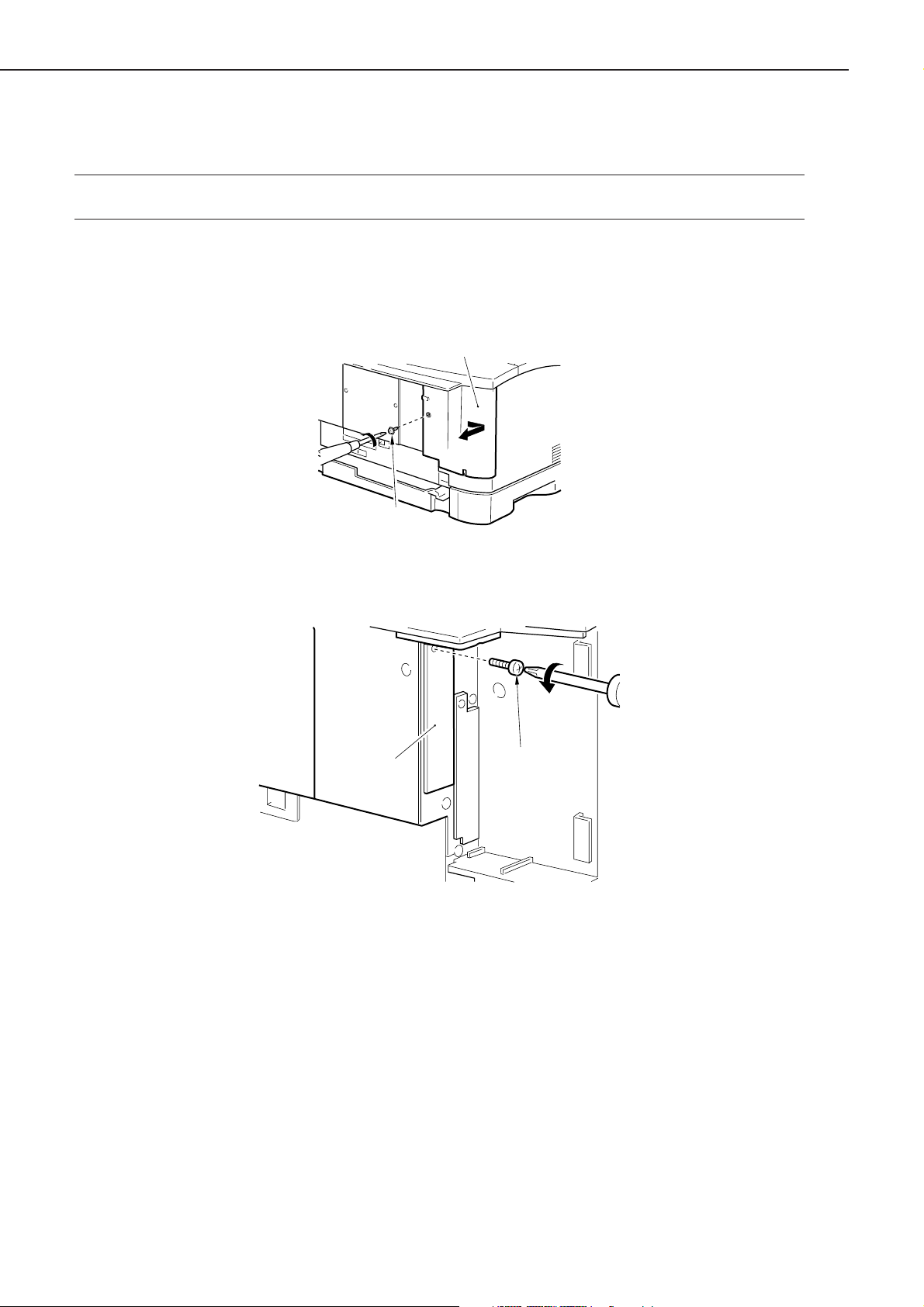
4) Remove the screw [1], and detach the expansion board slot cover [2].
[2]
[1]
Figure 1-5-2
5) Remove the screw [3], and detach the expansion board slot 1 cover [4].
[4]
[3]
Figure 1-5-3
1 - 12
CHAPTER 1
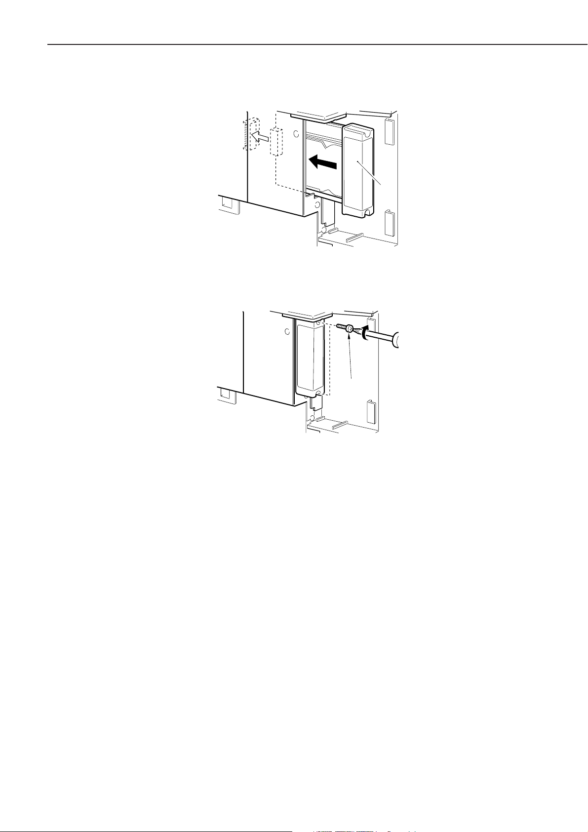
6) Holding the metal cover area [5] of the hard disk, slide in the hard disk along the guide rail.
[5]
Figure 1-5-4
7) Secure the top and bottom of the hard disk with the 2 screws [6] that come with the hard disk.
[6]
Figure 1-5-5
8) Attach the expansion board slot cover and the power cord.
9) Connect the Printer’s power cord to the power outlet.
1 - 13
CHAPTER 1
4 . Unpacking and installing the built-in print server (Ether Board EB-65)
Caution: If possible, wear a wrist strap designed to prevent damage by static charges. The static
charges in your body can damage the electric mechanisms when you install the built-in
print server to the Printer.
Take particular care not to touch the parts in electric circuits.
1) Unpack the print server.
2) Take out the print sever from its packaging box.
3) Remove the vinyl bag used to cover the print server.
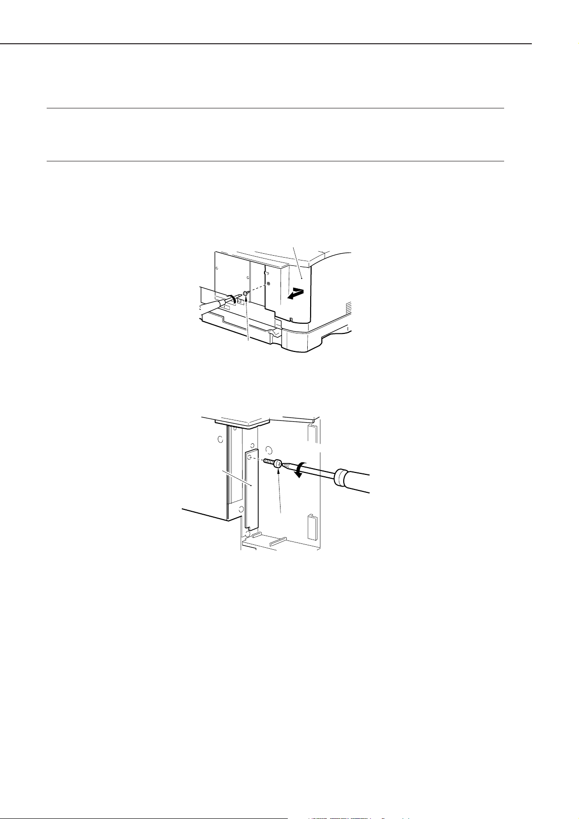
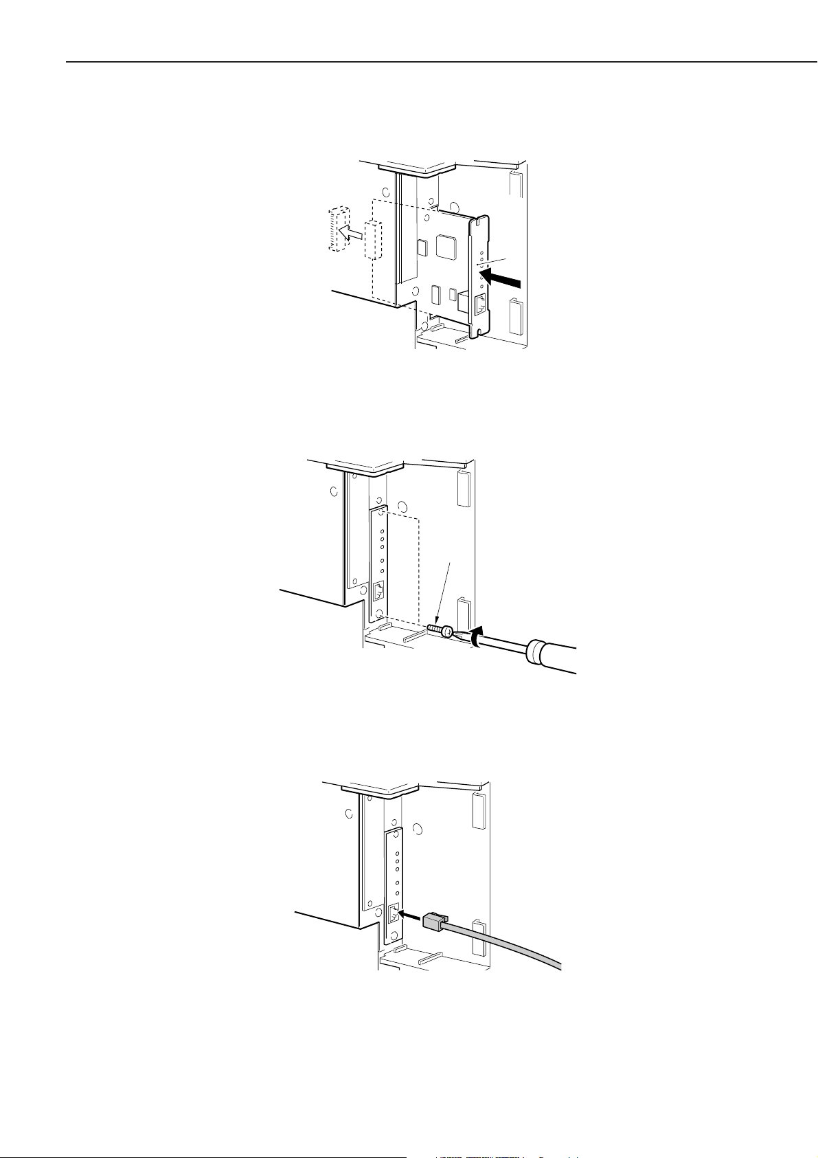
4) Remove the screw [1], and detach the expansion board slot cover [2].
[2]
[1]
Figure 1-5-6
5) Remove the screw [3], and detach the expansion board slot 2 cover [4].
[4]
[3]
Figure 1-5-7
1 - 14
CHAPTER 1
6) Slide in the print sever [5] into the expansion board slot 2 along the groove found inside.
[5]
Figure 1-5-8
7) Secure the top and bottom of the print server using the two screws [6] that come with the print
server.
[6]
Figure 1-5-9
8) Connect the network cable to the connector of the print server to suit the network environ-
ment.
Figure 1-5-10
9) Connect the power cord.
10) Connect the Printer’s power cord to the power outlet.
1 - 15
CHAPTER 1
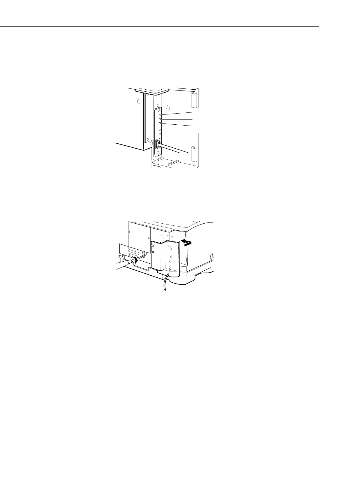
11) Turn on the power switch, and check to make sure that the LNK lamp (green) of the print
server is ON.
• In the case of 10Base-T, check to make sure that the LNK lamp is ON.
• In the case of 100Base-T, check to make sure that the LNK lamp and the 100 lamp are ON.
R
R
E
K
N
L
0
0
1
TXD
RXD
ERR lamp
LNK lamp
100 lamp
Figure 1-5-11
12) Turn on the power switch.
13) Thread the LAN cable through the groove in the expansion board slot cover, and secure the
expansion board slot cover with a screw.
Figure 1-5-12
5 . Checking the operation
1) Put paper in the cassette.
2) Connect the grounding wire to the Printer.
3) Connect the power cord to the Printer and the power outlet, and turn on the power switch. Be
sure that the power cord is one designed for the Printer.
4) When the Printer is in standby state, press the Go key so that it enters off-line state.
5) Press the Menu key once, and press the Item key until the status indicator panel indicates
‘TEST PRINT’.
6) Press the Enter key to execute ‘TEST PRINT’. Check the test print for faulty images. If an
option has been installed, check to make sure that its presence is indicated.
7) Clean up the area around the Printer, and set the Printer ready for use.
1 - 16

CHAPTER 1
6 . Points to note when using the printer
1. When turning on the power switches, be sure to start with the external devices and then the
Printer. To turn off the power switches, be sure to start with the Printer and then the external
devices. If you turn on/off an external device while the printer is ON, noise can be introduced
to the Printer through the cable connecting the device and the Printer, causing an error in the
Printer.
2. Whenever connecting the Printer with an external device, be sure to turn off the power switches
of both and disconnect the power cords from the outlets. A fault can occur if the connector is
connected or disconnected while the power switch is ON.
3. Be sure to turn off the power switch of the Printer before installing or removing the following:
flash memory (option), Adobe PostScript Level 3 Module (option), expansion RAM DIMM (option), hard disk (option), built-in print server (option).
4. Be sure to use a shielded cable when connecting the Printer’s parallel interface connector and
an external device. Moreover, make sure that the parallel interface cable is no longer than 3 m.
5. Be sure to use a twisted-pair LAN cable of Category 3 or higher when connecting the Printer’s
10Base-T/100Base-TX port and an external device to a 10Base-T network environment.
6. Be sure to use a twisted-pair LAN cable of Category 5 when connecting the Printer’s 10Base-T/
100Base-TX port and an external device to a 100Base-TX network environment.
7. Be sure not to touch the metal area of the connector before connecting or disconnecting the
USB cable while the power switch is ON.
8. Be sure to use SHUT DOWN MENU to shut down the printer if the optional Hard Disk HD-65
has been installed.
1 - 17
CHAPTER 1
D. When Storing or Handling the EP-65 Cartridge
The cartridge is subject to the effects of the environment it is in whether it remains packaged or
installed in the Printer, and it takes on changes over time regardless of how many pages it has
printed. The rate of change depends on the site of installation or storage, requiring full care when
handling and storing it.
a. Before taking out of the package (removing the signal)
When storing the cartridge in a warehouse or a workshop, be sure that the environment meets the
requirements in Table 1-5-1; in addition,
1. Avoid direct rays of the sun.
2. Avoid a place subject to vibration.
3. Avoid shocks as by hitting or dropping it.
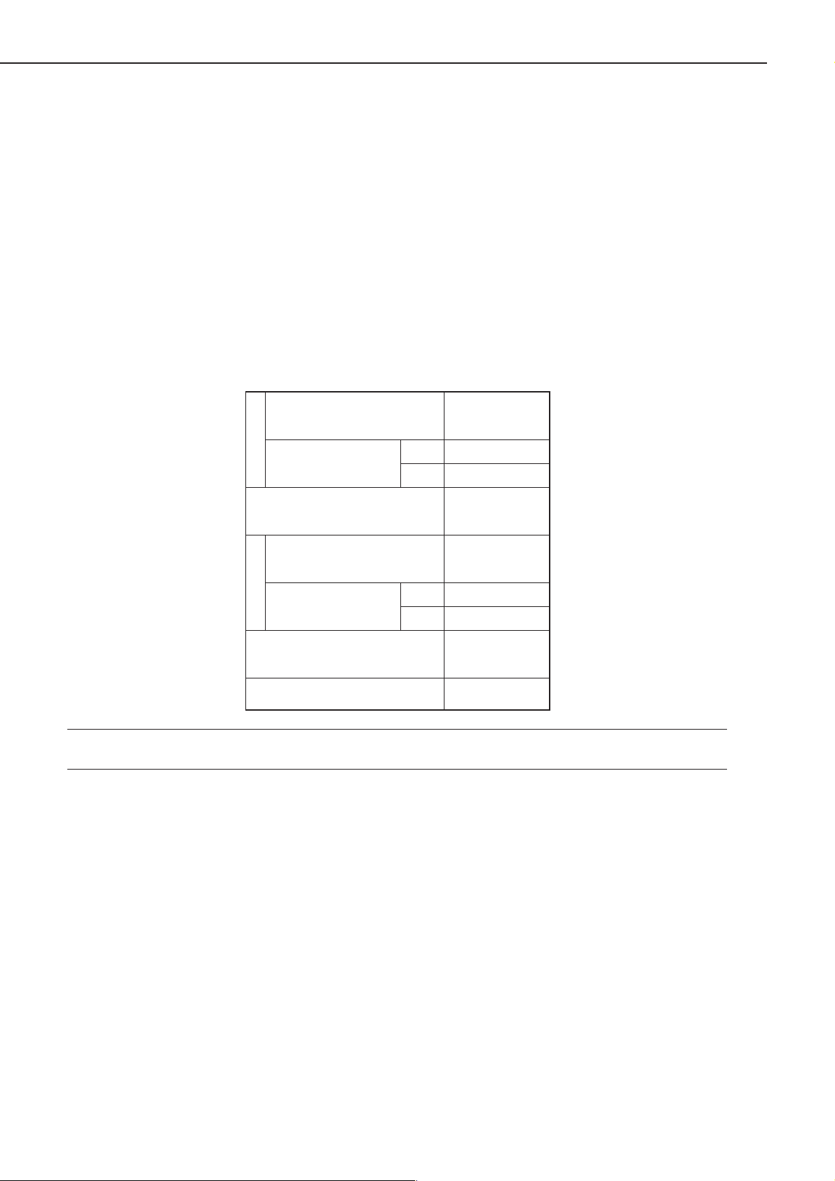
Table 1-5-1 Temperature/Humidity Requirements for Storage
Normal (9/10 of total
storage period)
Severe (1/10 of
TemperatureHumidity
total storage period)
Change in temperature
(within about 3 min)
Normal (9/10 of total
storage period)
Severe (1/10 of
total storage period)
Atmospheric pressure
Total storage period
High
Low
High
Low
0 to 35˚C
35 to 40˚C
-20 to 0˚C
40˚C→15˚C
-20˚C→25˚C
35 to 85%RH
85 to 95% RH
10 to 35% RH
345 to 1013 hPa
(460 to 760 mmHg)
2.5 yr
Note: The total storage period refers to the period from the date of manufacture indicated on the
cartridge package.
1 - 18
CHAPTER 1
b. After taking out of the package (removing the seal)
The photosensitive drum is made of photoconducting material (OPC), and tends to deteriorate
when exposed to strong light. The toner is also kept inside the cartridge, requiring care after the
cartridge has been taken out its the package. Advise the user to take full care when handling/
storing the cartridge.
1 . Storing the cartridge after taking out of the package (removing the seal)
1. Be sure to keep it in a protective bag.
2. Avoid areas exposed to direct rays of the sun or near windows. Do not leave it in side a car for
a long time, as the rise in temperature can be extreme.
3. Avoid areas subject to high/low temperature/humidity or areas subject to extreme changes in
temperature or humidity.
4. Avoid areas subject to corrosive gases (e.g., insecticide) or areas subject to briny air.
5. Make sure that the temperature is between 0ºC and 35ºC.
6. Avoid CRT displays, disk drives, or floppy disks.
7. Keep it out of reach of children.
2 . Effective period
The cartridge is verified to remain good for 2.5 years after the date of manufacture, indicated on its
body using an abbreviated notation. For the user, the period is indicated on the package and the
packing boxes (year, month; 2.5 years after the date of manufacture).
The use of a cartridge after the date indicated may not bring about expected print quality,
making it desirable to use it up before the date indicated.
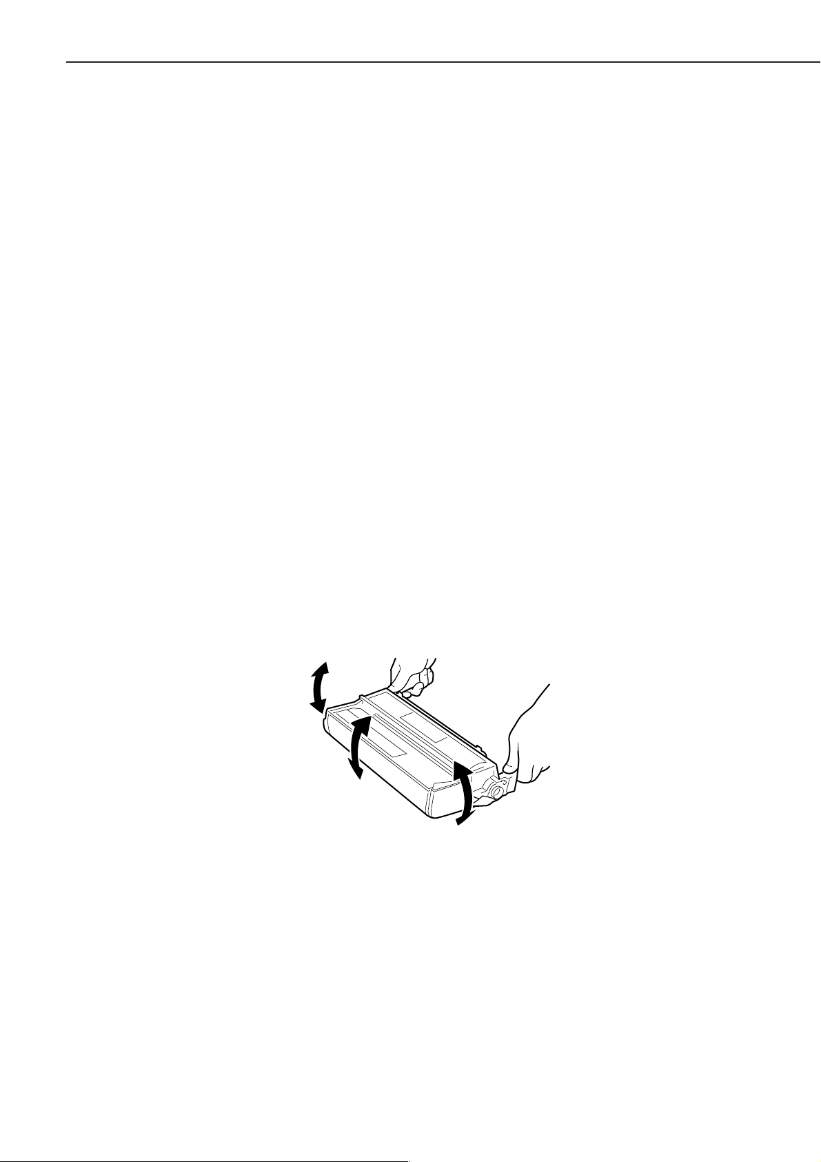
c . Points to note when handling
1. When fitting a new cartridge, or if some areas of the output image show white spots because of
an uneven level of the toner inside the cartridge, hold the cartridge as shown, and shake it
carefully to the left and right [1] about 5 to 6 times then up and down [2] about 5 to 6 times to
even out the toner.
[1]
[2]
[1]
Figure 1-5-13
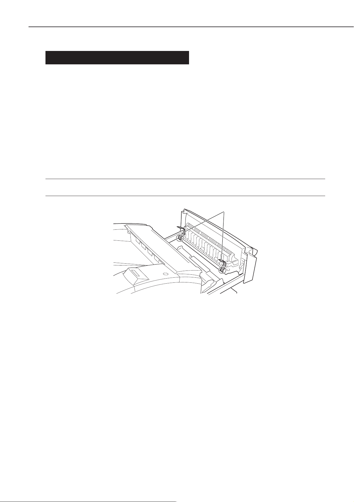
2. When transporting the Printer after taking out the cartridge from it, be sure to secure the
transfer charging roller in place for protection. Keep the cartridge in a protective bag to avoid
light. (See VI. ‘Relocating the Printer.’)
3. Do not place the cartridge near a CRT display, disk drive, or floppy disk. The magnetism from
the cartridge can damage the data.
4. The photosensitive drum is vulnerable to strong light. Avoid subjecting it to direct rays of the
sun or light 1500 lux or higher in strength. When exposed, it can produce images with white
spots or black bands. (If they occur, leave the machine alone for a while to correct the faults. If
the exposure is long, however, white spots or black bands may continue.)
1 - 19

CHAPTER 1
5. Do not attempt to touch the surface of the photosensitive drum of the cartridge. Further, do
not clean the photosensitive drum.
Drum
Figure 1-5-14
6. Do not place the cartridge upright or turn it over. Be sure it is laid with the label surface facing
upward.
7. Do not disassemble the cartridge.
Reference: If the photosensitive drum is exposed to light of 1500 lux (general lighting) for 5 min
and then left alone in the dark for 5 min, the faults can be corrected to a level satisfactory to practical uses. It is nevertheless important to avoid direct rays of the sun,
which is about 10000 to 30000 lux in intensity.
1 - 20
CHAPTER 1
VI. RELOCATING THE PRINTER
If the Printer must be relocated after installation by truck or other means of transportation, take
note of the following:
1 . Moving the printer with the cartridge removed
Once the cartridge is removed, the transfer charging roller can become displaced. Secure the
transfer charging roller in place using tape as follows before starting to move the Printer:
• If shipping tape is used, be sure to attach it so that the tape protection is over the gears and
the bushings, thus protecting the gears and the bushings of the transfer charging roller from
adhesive.
• If common tape is to be used, be sure to put a protective material (e.g., lint-free paper) between
the tape and the gears/bushings, thus protecting the gears and the bushings of the transfer
charging roller form adhesive.
Note: If the adhesive of the tape came into contact with a gear or a bushing, be sure to clean it
before using it.
Figure 1-6-1
Tape
1 - 21
CHAPTER 1
VII. ROUTINE MAINTENANCE/INSPECTION BY THE USER
To ensure that the Printer remains in its best condition, advise the user to provide the following
maintenance:
1 . Cartridge
If the images are fuzzy or show white spots, or the cartridge is running out of toner, shake or
replace the cartridge.
2 . Cassette pickup poller/cassette separation pad
If pickup faults tend to occur, wipe the pickup roller/separation pad with a cloth moistened with
water, and then dry wipe it. If the faults still occur, replace both cassette pickup roller and cassette
separation pad at the same time (at about 80,000th page; see Chapter 3 IV-A-1/2 “Replacing the
Cassette Pickup Roller” and “Replacing the Cassette Separation Pad.”)
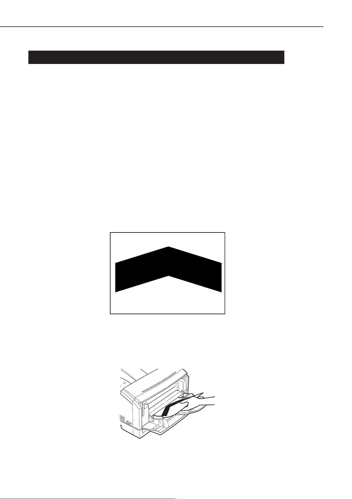
3 . Fixing roller
If the back or face of printed sheets have black dots, clean the fixing roller as follows:
1) Prepare an A4 or LTR sheet of paper for printing.
2) Press the Go key so that the Printer enters off-line state.
3) Press the Menu key until the status indicator panel indicates ‘TEST MENU’.
4) Press the Item key until the status indicator panel indicates ‘TEST MENU CLEANING PAGE’.
Then, press the Enter key so that a cleaning sheet (Figure 1-7-1) will be printed.
Figure 1-7-1
5) Press the Go key so that the Printer enters on-line state, then press the Menu key.
6) Open the multifeeder tray, and place the cleaning sheet generated in step 2) with its arrow side
facing upward and the arrow pointing at the rear of the Printer.
Figure 1-7-2
1 - 22
CHAPTER 1
7) Press the Go key so that the Printer starts cleaning the fixing roller.
Note: Allow about 5 min before the cleaning sheet is delivered to the delivery tray after cleaning
is started.
8) Press Go key to bring the printer on-line state.
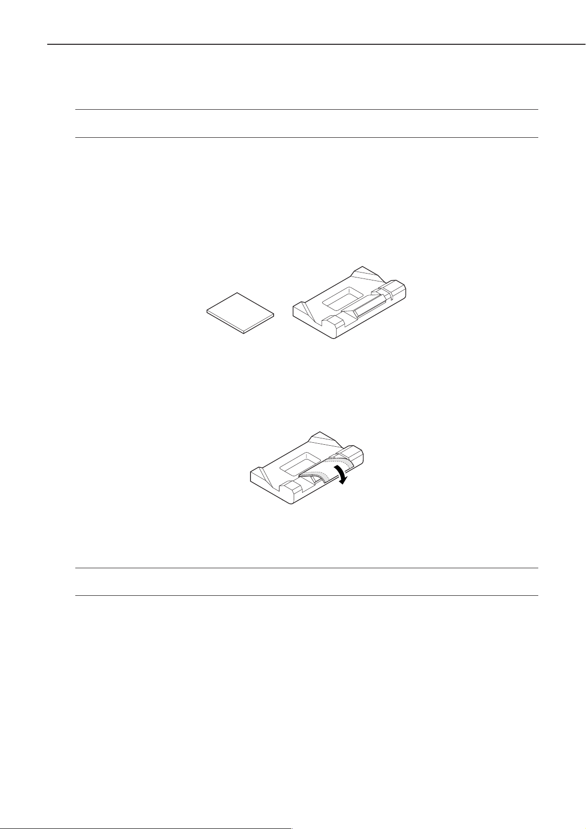
4 . Manual feed pickup roller
If pickup faults start to occur often because of glue or lint from recycled paper, advise the user to
purchase the following for cleaning the pickup roller; if faults still occur after cleaning, the manual
feed pickup roller and the manual feed separation pad must be replaced at the same time (about
50,000 pages).
1) Obtain a manual feed tray cleaning tool and a cleaning sponge.
Cleaning sponge
2) Peel the sticker from the cleaning sponge, and attach it as shown to the manual feed cleaning
tool.
3) Moisten the sponge portion of the manual feed tray cleaning tool with water.
Note: Be sure the sponge is no more than moist. If water shows when the sponge portion is
touched, shake it well to rid it of water.
Manual feed tray cleaning tool
Figure 1-7-3
Figure 1-7-4
1 - 23
CHAPTER 1
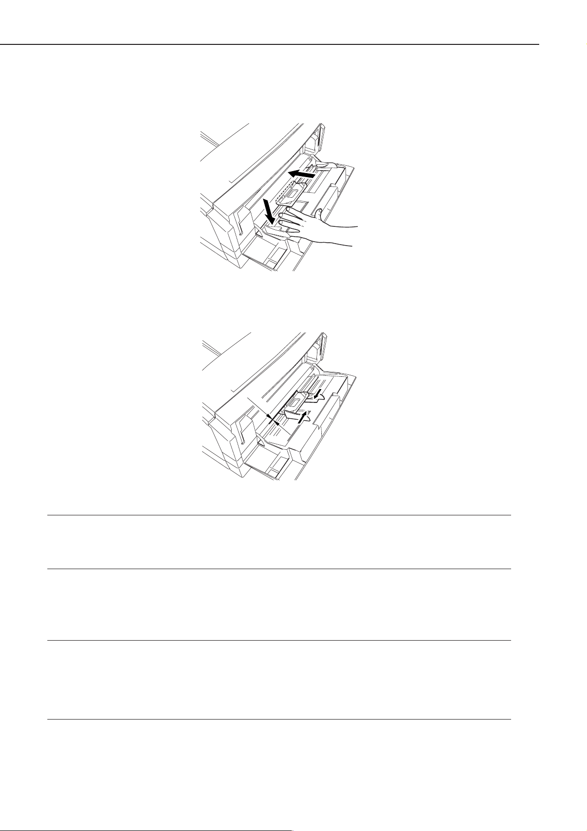
4) Open the manual feed tray; while pushing down the holding plate, fit the manual feed cleaning
tool in place as shown.
Figure 1-7-5
5) Set the paper guide of the multifeeder manual feed tray to postcard size.
To fit
Figure 1-7-6
Note: After fitting the manual feed tray cleaning tool in place, check to make sure that it has
been pushed so that the edge of the pickup guide and the step of the manual feed tray
cleaning tool. match. Otherwise, the dirt of the manual feed pickup roller cannot be removed.
5) Press the Go key so that the Printer enters off-line state.
6) Press the Menu key until the status indicator panel indicates ‘TEST MENU’.
7) Press the Item key until the status indicator panel indicates ‘CLEANING ROLLER’. Then, press
the Enter key so that the Printer starts to clean the roller.
Note: 1 . Check to make sure that no paper exists in the multifeeder tray before executing ‘CLEAN-
ING ROLLER’. Otherwise, the paper will be picked up, causing a jam.
2. Be sure to detach the cleaning tool after cleaning the manual feed pick up roller.
3. Allow about 10 sec between the start and the end of cleaning.
4. After using it for thee cleaning sessions, or if its surface has become excessively soiled,
replace it with a new cleaning sponge.
7) Open the paper guide, and detach the cleaning tool while pushing down the Holding plate.
8) Press the Go key so the Printer enters on-line state.
1 - 24
 Loading...