


Mar 1 2007
Service Manual
iPF700 series
iPF700


Application
This manual has been issued by Canon Inc. for qualified persons to learn technical theory, installation, maintenance, and repair
of products. This manual covers all localities where the products are sold. For this reason, there may be information in this
manual that does not apply to your locality.
Corrections
This manual may contain technical inaccuracies or typographical errors due to improvements or changes in products. When
changes occur in applicable products or in the contents of this manual, Canon will release technical information as the need
arises. In the event of major changes in the contents of this manual over a long or short period, Canon will issue a new edition
of this manual.
The following paragraph does not apply to any countries where such provisions are inconsistent with local law.
Trademarks
The product names and company names used in this manual are the registered trademarks of the individual companies.
Copyright
This manual is copyrighted with all rights reserved. Under the copyright laws, this manual may not be copied, reproduced or
translated into another language, in whole or in part, without the written consent of Canon Inc.
COPYRIGHT © 2001 CANON INC.
Printed in Japan
Caution
Use of this manual should be strictly supervised to avoid disclosure of confidential information.
Introduction
Symbols Used
This documentation uses the following symbols to indicate special information:
Symbol Description
Indicates an item of a non-specific nature, possibly classified as Note, Caution, or Warning.
Indicates an item requiring care to avoid electric shocks.
Indicates an item requiring care to avoid combustion (fire).
Indicates an item prohibiting disassembly to avoid electric shocks or problems.
Indicates an item requiring disconnection of the power plug from the electric outlet.
Indicates an item intended to provide notes assisting the understanding of the topic in question.
Indicates an item of reference assisting the understanding of the topic in question.
Provides a description of a service mode.
Provides a description of the nature of an error indication.
Memo
REF.

Introduction
The following rules apply throughout this Service Manual:
1. Each chapter contains sections explaining the purpose of specific functions and the relationship between electrical and mechanical systems with reference to the timing of operation.
In the diagrams, represents the path of mechanical drive; where a signal name accompanies the symbol , the arrow indicates the
direction of the electric signal.
The expression "turn on the power" means flipping on the power switch, closing the front door, and closing the delivery unit door, which results in
supplying the machine with power.
2. In the digital circuits, '1'is used to indicate that the voltage level of a given signal is "High", while '0' is used to indicate "Low".(The voltage value, however, differs from circuit to circuit.) In addition, the asterisk (*) as in "DRMD*" indicates that the DRMD signal goes on when '0'.
In practically all cases, the internal mechanisms of a microprocessor cannot be checked in the field. Therefore, the operations of the microprocessors
used in the machines are not discussed: they are explained in terms of from sensors to the input of the DC controller PCB and from the output of the
DC controller PCB to the loads.
The descriptions in this Service Manual are subject to change without notice for product improvement or other purposes, and major changes will be communicated in the form of Service Information bulletins.
All service persons are expected to have a good understanding of the contents of this Service Manual and all relevant Service Information bulletins and be
able to identify and isolate faults in the machine."


Contents
Contents
Chapter 1 PRODUCT DESCRIPTION
1.1 Product Overview ....................................................................................................................................... 1- 1
1.1.1 Product Overview ....................................................................................................................................................1- 1
1.2 Features .....................................................................................................................................................1- 1
1.2.1 Features ..................................................................................................................................................................1- 1
1.2.2 Printhead ................................................................................................................................................................. 1- 2
1.2.3 Ink tanks ..................................................................................................................................................................1- 2
1.2.4 Cutter unit ................................................................................................................................................................1- 2
1.2.5 Roll holder ...............................................................................................................................................................1- 2
1.2.6 Stand .......................................................................................................................................................................1- 3
1.2.7 Expendables............................................................................................................................................................1- 3
1.3 Product Specifications ................................................................................................................................1- 5
1.3.1 Product Specifications .............................................................................................................................................1- 5
1.4 Detailed Specifications ...............................................................................................................................1- 6
1.4.1 Print speeds and print directions .............................................................................................................................1- 6
1.4.2 Interface specifications ............................................................................................................................................1- 7
1.5 Names and Functions of Components ....................................................................................................... 1- 8
1.5.1 Printer front panel....................................................................................................................................................1- 8
1.5.2 Printer rear panel ....................................................................................................................................................1- 8
1.5.3 Carriage...................................................................................................................................................................1- 9
1.6 Basic Operation ........................................................................................................................................1- 10
1.6.1 Operation panel .....................................................................................................................................................1- 10
1.6.2 Printer state transitions..........................................................................................................................................1- 11
1.6.3 Main menu.............................................................................................................................................................1- 11
1.7 Safety and Precautions ............................................................................................................................1- 18
1.7.1 Safety Precautions ................................................................................................................................................ 1- 18
1.7.1.1 Moving parts of the printer .................................................................................................................................................... 1- 18
1.7.1.2 Ink adhesion........................................................................................................................................................................... 1- 19
1.7.1.3 Live parts of the printer .......................................................................................................................................................... 1- 20
1.7.2 Other Precautions..................................................................................................................................................1- 21
1.7.2.1 Printhead................................................................................................................................................................................ 1- 21
1.7.2.2 Ink tanks................................................................................................................................................................................. 1- 22
1.7.2.3 Dealing with the printer .......................................................................................................................................................... 1- 22
1.7.3 Precautions When Servicing Printer......................................................................................................................1- 23
1.7.3.1 Tips on data stored in the printer ........................................................................................................................................... 1- 23
1.7.3.2 Confirming the Firmware Version .......................................................................................................................................... 1- 23
1.7.3.3 Precautions against Static Electricity ..................................................................................................................................... 1- 23
1.7.3.4 Precautions for Disassembly/Reassembly............................................................................................................................. 1- 23
1.7.3.5 Self-diagnostic Feature .......................................................................................................................................................... 1- 23
1.7.3.6 Disposing of the Lithium Battery ............................................................................................................................................ 1- 23
Chapter 2 TECHNICAL REFERENCE
2.1 Basic Operation Outline..............................................................................................................................2- 1
2.1.1 Printer Diagram ....................................................................................................................................................... 2- 1
2.1.2 Print Driving .............................................................................................................................................................2- 1
2.2 Firmware.....................................................................................................................................................2- 2
2.2.1 Operation Sequence at Power-on ...........................................................................................................................2- 2
2.2.2 Operation Sequence at Power-off ...........................................................................................................................2- 3
2.2.3 Print Control.............................................................................................................................................................2- 3
2.2.4 Print Position Adjustment Function..........................................................................................................................2- 5

Contents
2.2.5 Head Management ..................................................................................................................................................2- 5
2.2.6 Printhead Overheating Protection Control ...............................................................................................................2- 5
2.2.7 Pause between Pages.............................................................................................................................................2- 5
2.2.8 White Raster Skip ....................................................................................................................................................2- 5
2.2.9 Sleep Mode..............................................................................................................................................................2- 5
2.3 Printer Mechanical System......................................................................................................................... 2- 6
2.3.1 Outline......................................................................................................................................................................2- 6
2.3.1.1 Outline...................................................................................................................................................................................... 2- 6
2.3.2 Ink Passage .............................................................................................................................................................2- 7
2.3.2.1 Ink Passage ............................................................................................................................................................................. 2- 7
2.3.2.2 Ink Tank Unit ............................................................................................................................................................................ 2- 8
2.3.2.3 Carriage Unit .......................................................................................................................................................................... 2- 10
2.3.2.4 Printhead................................................................................................................................................................................ 2- 13
2.3.2.5 Purge Unit .............................................................................................................................................................................. 2- 14
2.3.2.6 Maintenance Cartridge........................................................................................................................................................... 2- 18
2.3.2.7 Air Flow .................................................................................................................................................................................. 2- 18
2.3.3 Paper Path.............................................................................................................................................................2- 19
2.3.3.1 Outline.................................................................................................................................................................................... 2- 19
2.3.3.2 Paper Path ............................................................................................................................................................................. 2- 20
2.3.3.3 Cutter Unit .............................................................................................................................................................................. 2- 20
2.4 Printer Electrical System .......................................................................................................................... 2- 21
2.4.1 Outline....................................................................................................................................................................2- 21
2.4.1.1 Overview ................................................................................................................................................................................ 2- 21
2.4.2 Main Controller.......................................................................................................................................................2- 22
2.4.2.1 Main controller components ................................................................................................................................................... 2- 22
2.4.3 Carriage Relay PCB...............................................................................................................................................2- 23
2.4.3.1 Carriage relay PCB components ........................................................................................................................................... 2- 23
2.4.4 Head Relay PCB....................................................................................................................................................2- 23
2.4.4.1 Head relay PCB components................................................................................................................................................. 2- 23
2.4.5 Maintenance Cartridge Relay PCB ........................................................................................................................2- 24
2.4.5.1 Maintenance cartridge relay PCB components...................................................................................................................... 2- 24
2.4.6 Power Supply.........................................................................................................................................................2- 24
2.4.6.1 Power supply block diagram .................................................................................................................................................. 2- 24
2.5 Detection Functions with Sensors ............................................................................................................ 2- 25
2.5.1 Sensers for covers .................................................................................................................................................2- 25
2.5.2 Ink passage system ...............................................................................................................................................2- 26
2.5.3 Carriage system.....................................................................................................................................................2- 28
2.5.4 Paper path system.................................................................................................................................................2- 29
Chapter 3 INSTALLATION
3.1 Transporting the Printer.............................................................................................................................. 3- 1
3.1.1 Transporting the Printer ...........................................................................................................................................3- 1
3.1.1.1 Transporting the Printer ........................................................................................................................................................... 3- 1
3.1.2 Reinstalling the Printer.............................................................................................................................................3- 2
3.1.2.1 Reinstalling the Printer ............................................................................................................................................................. 3- 2
Chapter 4 DISASSEMBLY/REASSEMBLY
4.1 Service Parts .............................................................................................................................................. 4- 1
4.1.1 Service Parts............................................................................................................................................................4- 1
4.2 Disassembly/Reassembly .......................................................................................................................... 4- 1
4.2.1 Disassembly/Reassembly........................................................................................................................................4- 1
4.3 Points to Note on Disassembly and Reassembly....................................................................................... 4- 2
4.3.1 Note on locations prohibited from disassembly .......................................................................................................4- 2
4.3.2 Manual carriage movement .....................................................................................................................................4- 3
4.3.3 Units required for draining the ink............................................................................................................................4- 3
4.3.4 Outer covers ............................................................................................................................................................4- 4

Contents
4.3.5 Waste ink box ..........................................................................................................................................................4- 9
4.3.6 Driving unit...............................................................................................................................................................4- 9
4.3.7 Ink tube unit .............................................................................................................................................................4- 9
4.3.8 Carriage unit ..........................................................................................................................................................4- 12
4.3.9 Feeder unit ............................................................................................................................................................4- 14
4.3.10 Purge unit ............................................................................................................................................................ 4- 15
4.3.11 Ink tank unit .........................................................................................................................................................4- 15
4.3.12 Head management sensor ..................................................................................................................................4- 16
4.3.13 multi sensor .........................................................................................................................................................4- 17
4.3.14 PCBs....................................................................................................................................................................4- 18
4.3.15 Opening the Caps and Moving the Wiper Unit ....................................................................................................4- 18
4.3.16 Opening/Closing the Ink Supply Valve ................................................................................................................4- 19
4.3.17 Draining the Ink....................................................................................................................................................4- 20
4.4 Applying the Grease .................................................................................................................................4- 21
4.4.1 Applying The Grease.............................................................................................................................................4- 21
4.5 Adjustment and Setup Items ....................................................................................................................4- 22
4.5.1 Procedure after Replacing the Feed Roller HP Sensor or Feed Roller Encoder...................................................4- 22
4.5.2 Procedure after Replacing the Carriage Unit or Multi Sensor ...............................................................................4- 22
4.5.3 Procedure after Replacing the Head Management Sensor ...................................................................................4- 23
Chapter 5 MAINTENANCE
5.1 Periodic Replacement Parts ....................................................................................................................... 5- 1
5.1.1 Periodic Replacement Parts ....................................................................................................................................5- 1
5.2 Consumable Parts ......................................................................................................................................5- 1
5.2.1 Consumable Parts ...................................................................................................................................................5- 1
5.3 Periodic Maintenance ................................................................................................................................. 5- 1
5.3.1 Periodic Maintenance ..............................................................................................................................................5- 1
Chapter 6 TROUBLESHOOTING
6.1 Troubleshooting.......................................................................................................................................... 6- 1
6.1.1 Outline .....................................................................................................................................................................6- 1
6.1.1.1 Outline of Troubleshooting ....................................................................................................................................................... 6- 1
6.1.2 Troubleshooting by the Phenomenon......................................................................................................................6- 1
6.1.2.1 Incorrect Value Check Value ................................................................................................................................................... 6- 1
6.1.2.2 Load roll. .................................................................................................................................................................................. 6- 1
6.1.2.3 Load sheets. /Remove sheets. ............................................................................................................................................... 6- 1
6.1.2.4 Open Ink Tank Cover ............................................................................................................................................................... 6- 1
6.1.2.5 The printer cannot be turned on. ............................................................................................................................................. 6- 2
6.1.2.6 The printer is shut down during power-on or printing............................................................................................................... 6- 2
6.1.2.7 The printer cannot be connected over the network. ................................................................................................................ 6- 2
6.1.2.8 Printing error (Ink remains.) ..................................................................................................................................................... 6- 2
6.1.2.9 Other printing errors................................................................................................................................................................. 6- 3
6.1.3 Troubleshooting When Warnings Occur..................................................................................................................6- 3
6.1.3.1 Ink Level: Check(1000/1001/1002/1003/1006/1007) ............................................................................................................... 6- 3
6.1.3.2 Check maint cartridge capacity.(1100) .................................................................................................................................... 6- 3
6.1.3.3 End of paper feed. Cannot feed paper more. (100F) ............................................................................................................... 6- 3
6.1.3.4 GARO W12xx (xx: Digits) (1221,1222,1223,1225,1231,1232,1233,1234,1235) ..................................................................... 6- 3
6.1.4 Troubleshooting When Errors Occur .......................................................................................................................6- 3
6.1.4.1 03010000-200C/03010000-2017/03010000-2018/03016000-2010 Multi sensor error............................................................ 6- 3
6.1.4.2 03010000-200D Cut media end error ...................................................................................................................................... 6- 4
6.1.4.3 03010000-2016 Paper feed/delivery jam error ........................................................................................................................ 6- 4
6.1.4.4 03010000-2820/03010000-2821/03010000-2822/03010000-2823/03010000-2F33/031300312F32 Adjustment error .......... 6- 4
6.1.4.5 03010000-2E1F/03060000-2E14/03060A00-2E00/03061000-2E15/03860002-2E02/03860002-2E0A/03860002-2E0C Path
mismatch error ............................................................................................................................................................................... 6- 4
6.1.4.6 03030000-2E21 IEEE1394 Error ............................................................................................................................................. 6- 5
6.1.4.7 03031000-2E0F Upper cover sensor error .............................................................................................................................. 6- 5

Contents
6.1.4.8 03031000-2E11 Carriage cover sensor error .......................................................................................................................... 6- 5
6.1.4.9 03031000-2E12 Defective paper release lever ....................................................................................................................... 6- 5
6.1.4.10 03060A00-2E1B Roll media end error ................................................................................................................................... 6- 5
6.1.4.11 03130031-260E Gap detection error...................................................................................................................................... 6- 6
6.1.4.12 03130031-260F Gap adjustment error................................................................................................................................... 6- 6
6.1.4.13 03130031-2F13 A/D Converter external trigger output stopped ............................................................................................ 6- 6
6.1.4.14 03130031-2F14 ASIC Register cannot be written.................................................................................................................. 6- 6
6.1.4.15 03130031-2F16 Mist fan error................................................................................................................................................ 6- 6
6.1.4.16 03130031-2F17 Suction fan error .......................................................................................................................................... 6- 6
6.1.4.17 03130031-2F20/03130031-22/03130031-2F23/03130031-2F28/03130031-2F2D Defective sensor in purge unit ............... 6- 7
6.1.4.18 03130031-2F25 Carriage home position error ....................................................................................................................... 6- 7
6.1.4.19 03130031-2F26/03130031-2F27 Carriage motor error.......................................................................................................... 6- 7
6.1.4.20 03130031-2F2A Feed roller home position error ................................................................................................................... 6- 7
6.1.4.21 03130031-2F3A valve open/close error ................................................................................................................................ 6- 7
6.1.4.22 03800200-2802/03800400-2803/03800300-2801 Printhead error......................................................................................... 6- 7
6.1.4.23 03800500-280C Defective printhead nozzle ......................................................................................................................... 6- 8
6.1.4.24 03800500-2F2F/03800500-2F30 Head management sensor error ....................................................................................... 6- 8
6.1.4.25 03810101-2501/03810102-2502/03810103-2503/03810104-2500/03810106-2506/03810106-2507 No ink error ............... 6- 8
6.1.4.26 03810201-2581/03810202-2582/03810203-2583/03810204-2580/03810206-2586/03810206-2587 Tank level error 1 ...... 6- 8
6.1.4.27 03810201-2591/03810202-2592/03810203-2593/03810204-2590/03810206-2596/03810206-2597 Tank level error 2 ...... 6- 8
6.1.4.28 03830101-2521/03830102-2522/03830103-2523/03830104-2520/03830106-2526/03830105-2527 Ink tank is not installed. (
This error occurs when the ink tank is replaced.)........................................................................................................................... 6- 9
6.1.4.29 03830201-2541/03830202-2542/03830203-2543/03800204-2540/03830206-2546/03830206-2547 Invalid ink tank ID...... 6- 9
6.1.4.30 03830301-2561/03830302-2562/03830303-2563/03830304-2560/03830306-2566/03830306-2567 Ink tank EEPROM error 6-
9
6.1.4.31 03841001-2819/03841001-281B/03841101-2818/03841201-2816/03841201-2817 Maintenance cartridge error................ 6- 9
6.1.4.32 03861001-2405/03861001-2406 Borderless printing error .................................................................................................... 6- 9
6.1.4.33 03862000-2E09 Insufficient roll media error ........................................................................................................................ 6- 10
6.1.4.34 03870001-2015 Cutter error................................................................................................................................................. 6- 10
6.1.4.35 03900001-4042/03900001-4049 Firmware error ................................................................................................................. 6- 10
6.1.4.36 E194-4034 Sensor calibration error ..................................................................................................................................... 6- 10
6.1.5 Troubleshooting When Service Call Errors Occur .................................................................................................6- 10
6.1.5.1 E141-4046 Recovery system's rotation count reached 50,000.............................................................................................. 6- 10
6.1.5.2 E144-4047 Supply system's count error ................................................................................................................................ 6- 11
6.1.5.3 E146-4001 Borderless/idle ejection/mist collection count full ................................................................................................ 6- 11
6.1.5.4 E161-403E Abnormally high head temperature ..................................................................................................................... 6- 11
6.1.5.5 E194-404A Non-discharge detection count error................................................................................................................... 6- 11
6.1.5.6 E196-4040/E196-4041/E196-4042/E196-4043/E196-4044/E196-4045 Main controller PCB error ....................................... 6- 11
6.1.5.7 E198-401C/E198-401D/E198-401E RTC error ..................................................................................................................... 6- 11
6.2 Location of Connectors and Pin Arrangement ......................................................................................... 6- 12
6.2.1 Main controller PCB...............................................................................................................................................6- 12
6.2.2 Carriage relay PCB................................................................................................................................................6- 17
6.2.3 Head relay PCB .....................................................................................................................................................6- 21
6.3 Version Up................................................................................................................................................ 6- 23
6.3.1 Firmware Update Tool ...........................................................................................................................................6- 23
6.4 Service Tools............................................................................................................................................ 6- 24
6.4.1 List of Tools............................................................................................................................................................6- 24
6.4.2 Using the Cover Switch Tool..................................................................................................................................6- 24
Chapter 7 SERVICE MODE
7.1 Service Mode ............................................................................................................................................. 7- 1
7.1.1 Service Mode...........................................................................................................................................................7- 1
7.1.2 Service Mode Map...................................................................................................................................................7- 1
7.1.3 Details of Service Mode...........................................................................................................................................7- 5
7.2 Special Mode............................................................................................................................................ 7- 11
7.2.1 Special Modes for Servicing ..................................................................................................................................7- 11
Chapter 8 ERROR CODE

Contents
8.1 Outline ........................................................................................................................................................ 8- 1
8.1.1 Outline .....................................................................................................................................................................8- 1
8.2 Warning Table ............................................................................................................................................ 8- 1
8.2.1 Warnings .................................................................................................................................................................8- 1
8.3 Error Table..................................................................................................................................................8- 1
8.3.1 Error Code List ........................................................................................................................................................8- 1
8.4 Sevice Call Table........................................................................................................................................8- 3
8.4.1 Service call errors....................................................................................................................................................8- 3

Contents

Chapter 1 PRODUCT DESCRIPTION


Contents
Contents
1.1 Product Overview ..........................................................................................................................................................1-1
1.1.1 Product Overview ........................................................................................................................................................................ 1-1
1.2 Features ..........................................................................................................................................................................1-1
1.2.1 Features ........................................................................................................................................................................................ 1-1
1.2.2 Printhead ...................................................................................................................................................................................... 1-2
1.2.3 Ink tanks....................................................................................................................................................................................... 1-2
1.2.4 Cutter unit .................................................................................................................................................................................... 1-2
1.2.5 Roll holder ................................................................................................................................................................................... 1-2
1.2.6 Stand ............................................................................................................................................................................................ 1-3
1.2.7 Expendables ................................................................................................................................................................................. 1-3
1.3 Product Specifications....................................................................................................................................................1-5
1.3.1 Product Specifications ................................................................................................................................................................. 1-5
1.4 Detailed Specifications ..................................................................................................................................................1-6
1.4.1 Print speeds and print directions .................................................................................................................................................. 1-6
1.4.2 Interface specifications ................................................................................................................................................................ 1-7
1.5 Names and Functions of Components ...........................................................................................................................1-8
1.5.1 Printer front panel ........................................................................................................................................................................ 1-8
1.5.2 Printer rear panel ......................................................................................................................................................................... 1-8
1.5.3 Carriage........................................................................................................................................................................................ 1-9
1.6 Basic Operation............................................................................................................................................................1-10
1.6.1 Operation panel .......................................................................................................................................................................... 1-10
1.6.2 Printer state transitions............................................................................................................................................................... 1-11
1.6.3 Main menu ................................................................................................................................................................................. 1-11
1.7 Safety and Precautions.................................................................................................................................................1-18
1.7.1 Safety Precautions...................................................................................................................................................................... 1-18
1.7.1.1 Moving parts of the printer .......................................................................................................................................................................... 1-18
1.7.1.2 Ink adhesion .................................................................................................................................................................................................. 1-19
1.7.1.3 Live parts of the printer .................................................................................................................................................................................1-20
1.7.2 Other Precautions ....................................................................................................................................................................... 1-21
1.7.2.1 Printhead .......................................................................................................................................................................................................1-21
1.7.2.2 Ink tanks ........................................................................................................................................................................................................1-22
1.7.2.3 Dealing with the printer ................................................................................................................................................................................1-22
1.7.3 Precautions When Servicing Printer .......................................................................................................................................... 1-23
1.7.3.1 Tips on data stored in the printer...................................................................................................................................................................1-23
1.7.3.2 Confirming the Firmware Version ................................................................................................................................................................1-23
1.7.3.3 Precautions against Static Electricity ............................................................................................................................................................1-23
1.7.3.4 Precautions for Disassembly/Reassembly..................................................................................................................................................... 1-23
1.7.3.5 Self-diagnostic Feature..................................................................................................................................................................................1-23
1.7.3.6 Disposing of the Lithium Battery..................................................................................................................................................................1-23

Chapter 1
1-1
1.1 Product Overview
1.1.1 Product Overview
0012-6185
This printer is a large-format printer that prints in a maximum width of 36 inches with high-speed photographic picture quality.
This printer is a desktop product that delivers its output on roll media or cut sheets.
F-1-1
T-1-1
1.2 Features
1.2.1 Features
0012-6186
-Rear loading of roll media, making for compact, lightweight device geometry.
-Borderless four-side printing support (roll media) removes laborious cutting work, easing the job of creating posters to a significant degree.
-High resolutions of 2400 x 1200 dpi maximum, coupled with the exceptionally light-fast, water-proof and ozone-proof five-color pigment inks of Y, M, C, BK
and MBK, deliver high-quality photographic picture quality.
-High-speed printing under bidirectional print control.
-Ink supply through tubing to a completely independent printhead and large-capacity ink tanks.
-Ready for roll media and cut media.
-Roll media pass in widths between 254 and 914.4 mm and in lengths up to 18 m.
-The cutter unit that mounts on the carriage allows paper to be cut automatically.
-Cut media are fed and ejected and ink tanks replaced all in an easy-to-access front panel operation.
-USB2.0 high-speed interface and 10Base-T/100Base-TX in standard support of a TCP/IP network, plus optional support of IEEE1394.
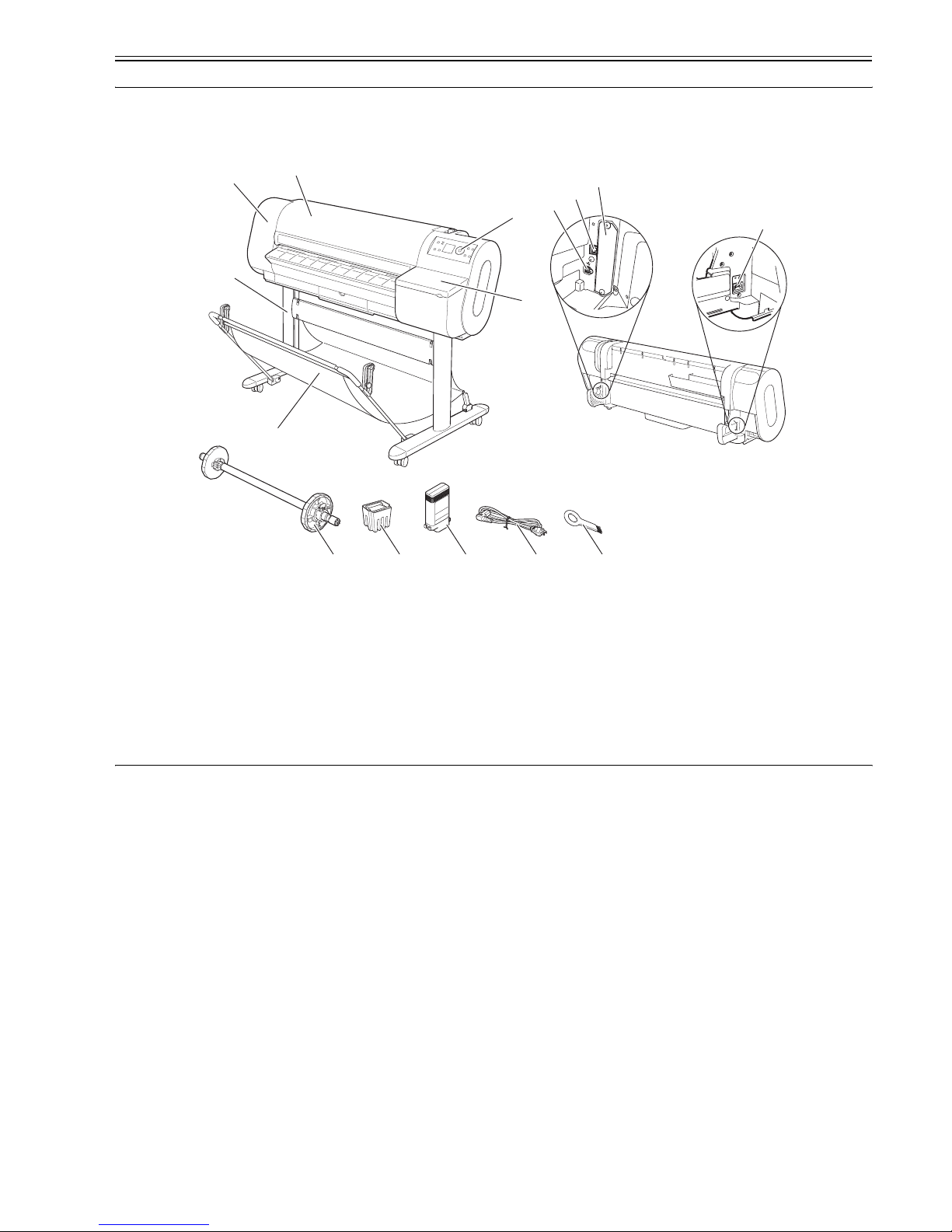
[1] Top Cover [9] USB Port
[2] Upper Left Cover [10] Power Supply Connector
[3] Stand (option) [11] Roll Holder Set
[4] Output Stacker (included with stand) [12] Printhead
[5] Operation Panel [13] Ink Tank
[6] Ink Tank Cover [14] Power Cord
[7] Expansion Board Slot [15] Cleaner Brush
[8] Ethernet Connector
[7]
[8]
[9]
[10]
[11] [12] [13] [14] [15]
[2]
[1]
[3]
[4]
[6]
[5]
Chapter 1
1-2
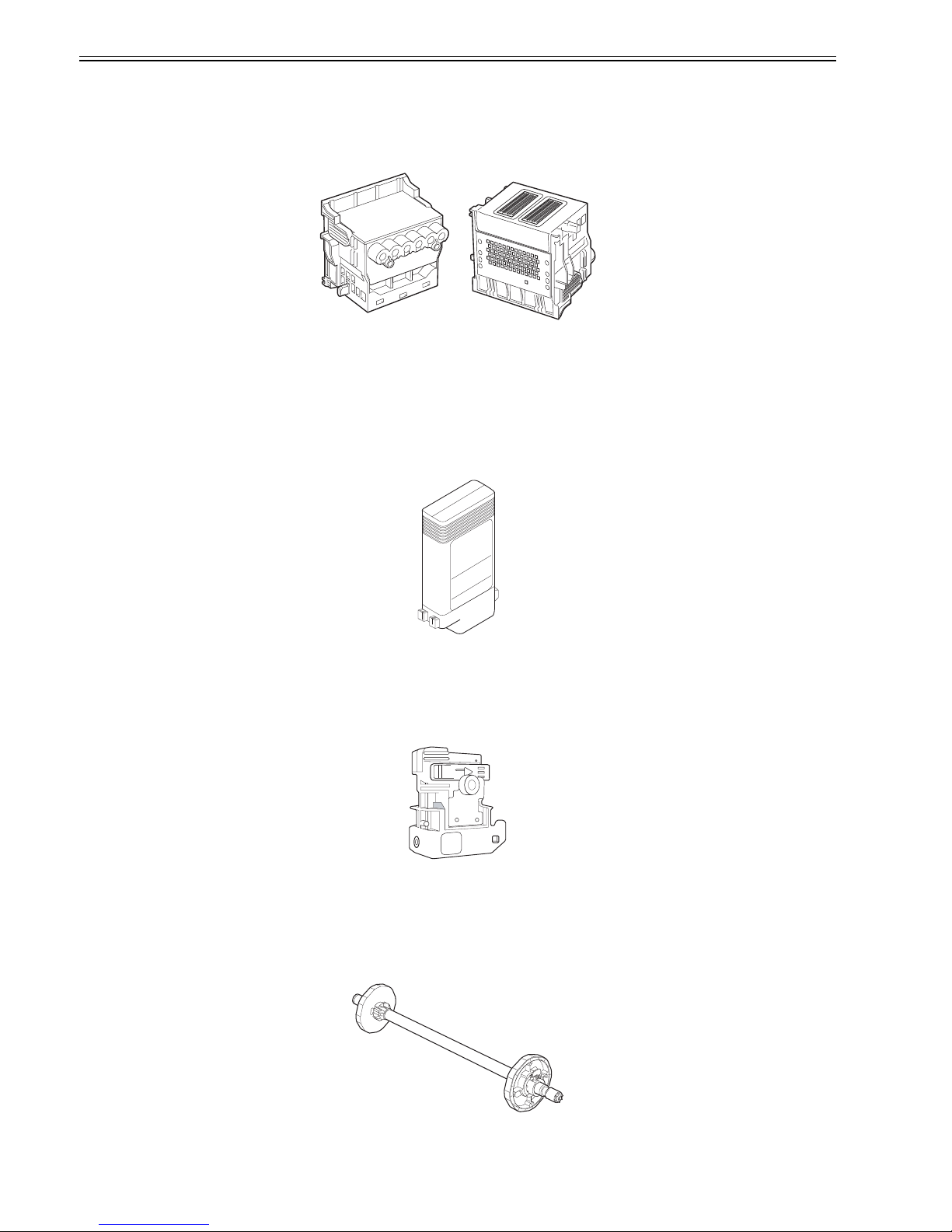
1.2.2 Printhead
0013-2741
The printhead that mounts on the carriage is an integrated six-color disposable printhead.
It has 5,120 nozzles for MBK and 2,560 nozzles for each additional color arranged in a zigzag pattern.
If print quality remains unimproved even after a specified cleaning operation, replace the printhead. Replacement about one year after the date of initial unpacking
is also recommended.
F-1-2
1.2.3 Ink tanks
0013-0607
Ink tanks are disposable.
An ink tank should be replaced when an ink tank replacement prompt message appears or when six months expire after the date of initial unpacking, whichever
occurs earlier.
To install ink tanks, open the right cover of the printer. Ink tanks are furnished with a notch for preventing incorrect installation, which will allow the tanks to be
installed at the position marked in the right color and nowhere else.
Ink tanks are available in the four dye ink colors of black, cyan, magenta and yellow and the pigment ink color of mat black.
F-1-3
1.2.4 Cutter unit
0013-5146
The cutter unit that mounts on the carriage is disposable.
Replace the cutter unit when it gets dull.
F-1-4
1.2.5 Roll holder
0013-4667
The printer comes with a roll holder for paper tubes having an inside diameter of 2 inches as standard. It supports an optional roller holder for paper tubes having
an inside diameter of 3 inches.
Both roll holders clamp the paper tubes of roll media with an outside diameter of 150 mm or less from inside.
F-1-5
Chapter 1
1-3
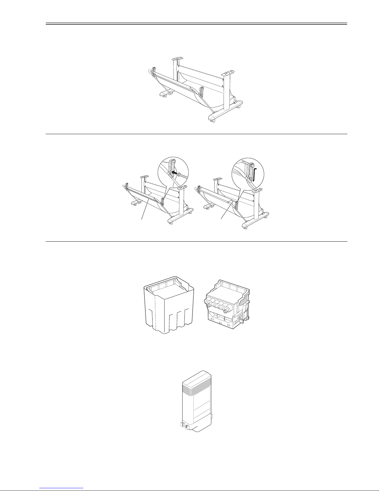
1.2.6 Stand
0016-4115
It is a stand that puts the printer. Equipped with casters so that the printer can be easily moved. The output stacker included with stand can use by the two ways of
the regular position or extended position.
F-1-6
MEMO:
Use the output stacker in the regular position [A]. However, for the specified media, it can also be used in the extended position [B]. The media can be removed
more easily when the output stacker is in the extended position.
F-1-7
1.2.7 Expendables
0013-2743
a. Printhead
The expendable printhead is the same as the one that comes with the printer.
F-1-8
b. Ink tanks
The expendable ink tanks are available in six colors: mat black, black, cyan, magenta and yellow. They are the same the same as the ones that come with the printer.
Usable for six months after unpacking.
F-1-9
c. Maintenance cartridge
The expendable maintenance cartridge is the same as the one that comes with the printer.
The maintenance cartridge is furnished with a shaft cleaner.
[A]
[B]

Chapter 1
1-4
F-1-10

Chapter 1
1-5
1.3 Product Specifications
1.3.1 Product Specifications
0012-6192
Type Bubble-jet printer (desktop type)
Feeding system Roll media: Manual (Rear loading)
Cut media: Paper tray (Front loading)
Feeding capacity Roll media: 1 roll (up to 150 mm in outside diameter)/Option roll holder:
Paper tubes with an inside diameter of 50.8 mm (2")/Option roll holder:
Paper tubes with an inside diameter of 76.2 mm (3")/Cut media: 1 sheet
Delivery method Face-up forward ejection
Sheet delivery capability 1 sheet (collected in a stacker)
Cutter Auto-cutter with replaceable cartridges
Type of media Plain paper, plain paper (bond paper), high-coloring plain paper,
recycled plain paper, recycled coated paper, coated paper, thick coated
paper, extra-thick coated paper, premium mat paper, colored coated
paper (yellow), gloss photo paper, gloss photo paper2, gloss photo paper
(thick), semigloss photo paper, semigloss photo paper2, semigloss photo
paper (thick), synthetic paper, synthetic paper (glued), synthetic paper
(with releasing glue), proof paper 2, newspaper proof paper 1, newspaper
proof paper 2, newspaper proof paper 3, tracing paper, translucent mat
films, clear films
Supported thickness 0.07 mm - 0.08mm
Media size (Roll media) Width: 254 mm - 914.4 mm
Length: 203.2 m - 18 m *1 Roll media up to 150 mm in outside diameter
Media size (Cut sheet) Width: 203.2 mm - 917 mm
Length: 203.2 mm - 1600 mm
Printable area (Roll media) Bordered printing: Internal area, excluding 3-mm top, bottom, and left
and right margins.
Borderless printing: Internal area, excluding 0-mm top, bottom, and left
and right margins.
* The printable area may vary with each type of paper media used.
Printable area (Cut sheet) Internal area, excluding a 3-mmn top margin, 23-mm bottom margin
and3-mm left and right margins.
*1 Borderless printing does not support cut media as yet.
*2 The printable area may vary with each type of paper media used.
Printing recommendation area
(Roll media)
Internal area, excluding a 20-mm top margin, 5-mm bottom margin, and
7-mm left and right margins.
Printing recommendation area
(Cut sheet)
Internal area, excluding a 20-mm top margin, 5-mm bottom margin, and
23-mm left and right margins.
Margins (Roll media) Roll media: 3 mm for top, bottom and left and right margins
Borderless roll media: 0 mm for top, bottom and left and right margins
Margins (Cut sheet) 3-mm top margin, 23- mm bottom margin and 3- mm left and right
margins
* Borderless printing does not support cut media as yet.
Emulation Not available.
Interface USB2.0 Hi-Speed
Network (10Base-T)
IEEE1394 (option)
Printhead/Ink Tank type Independent printhead and ink tanks
Printhead [PF-01] Integrated six-color MB 5,120 nozzles, 2,560 nozzles for each
additional color
Ink tank [PFI-102] MBK, BK, C, M, Y
Bundled: 90 ml
Expendable: 130 ml
Detection functions (Cover
system)
Head cap position sensor: Yes/ Cover open/closed sensor: Yes
Detection functions (Ink passage
system)
Ink tank sensor: Yes/Remaining ink level sensor: Yes/Maintenance
cartridge sensor: Yes/Used ink tank full sensor: Yes/Printhead sensor:
Yes
Detection functions (Carriage
system)
Paper slip sensor: Yes/Carriage position sensor: Yes/Carriage home
position sensor: Yes/Carriage cover open/closed sensor: Yes/Carriage
temperature sensor: Yes
Detection functions (Paper path
system)
Paper sensor: Yes/Leading and trailing paper end sensors: Yes/Paper
width sensor: Yes/Slant sensor: Yes/Paper release lever position sensor:
Yes/Roll media bottom sensor: Yes/ Remaining roll media sensor: Yes/
Feed roller rotation sensor: Yes
Operating noise Sound pressure level: 50 dB (A) or less, operating; 35 dB or less, idle
Acoustic power level: 6.3 Bels
Operating environment Temperature: 15-30 oC
Relative humidity: 10-80%RH (non-condensing)
Print quality guaranteed
environment
Temperature: 15-30 oC
Relative humidity: 10-80%RH
Power supply AC 100 V - 240 V (50 Hz/60 Hz)
Power consumption (Maximum) 140 W or less
Chapter 1
1-6
1.4 Detailed Specifications
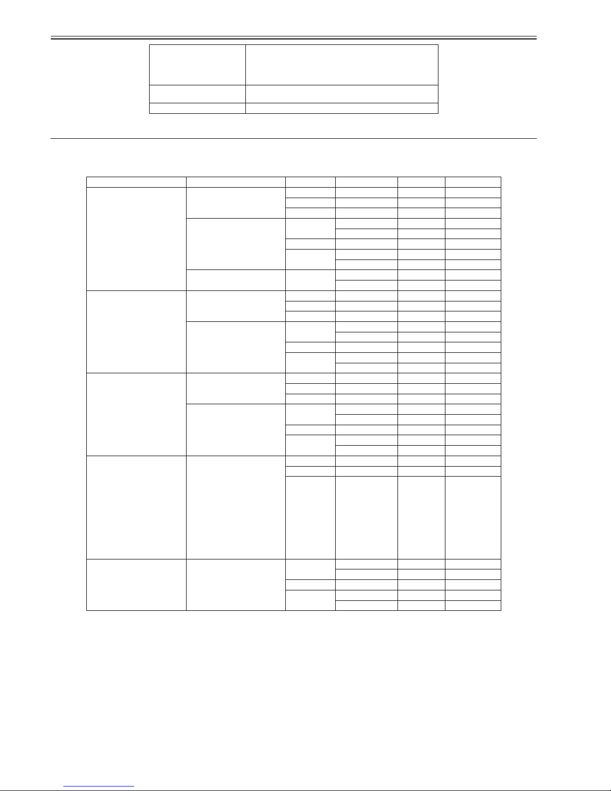
1.4.1 Print speeds and print directions
0013-6386
T-1-2
*1
Unidirectional printing may be automatically selected by the print engine according to the type of image to be printed (such as a graphic image). Unidirectional
printing can also be optionally selected from the printer driver.
* 2
Optionally selectable from the printer driver.
* 3
The printer drives an optimal pass count automatically to suit print data.
Power consumption When idle in energy save mode (sleep mode)
100-120 V: 5.0 W or less (with IEEE1394 mounted, 8 W or less)
220-240 V: 6.0 W or less ((with IEEE1394 mounted, 9 W or less)
When switched off (idle):
1 W or less
Printer unit dimensions
(WxDxH)
1507 mm (width) x 871 mm (depth) x 1094 mm (height) (including the
stand)
Weight Approx. 62 kg (including the stand)
Mediatype Prioritized picture quality Print quality Number of passes Direction (*1) Resolution
Plain paper
Plain paper (bond paper)
Plain paper (high-coloring)
Photographs and illustrations Fast 1 pass Bidirectional 1200 x 1200 dpi
Standard 2 passes Bidirectional 1200 x 1200 dpi
Fine 4 passes Bidirectional 1200 x 1200 dpi
Line drawings and text Fast (*2) 1 pass Bidirectional 1200 x 1200 dpi
1 pass Bidirectional 1200 x 1200 dpi
Standard 1 pass Bidirectional 1200 x 1200 dpi
Fine (*2) 2 passes Bidirectional 1200 x 1200 dpi
2 passes Bidirectional 1200 x 1200 dpi
Office characters Standard (*3) 1 pass Bidirectional 1200 x 1200 dpi
2 passes Bidirectional 1200 x 1200 dpi
Coated paper
Dedicated high-quality paper
Thick coated paper
Photographs and illustrations Standard 4 passes Bidirectional 1200 x 1200 dpi
Fine 8 passes Bidirectional 2400 x 1200 dpi
Maximum 12 passes Bidirectional 2400 x 1200 dpi
Line drawings and text Fast (*2) 1 pass Bidirectional 1200 x 1200 dpi
1 pass Bidirectional 1200 x 1200 dpi
Standard 2 passes Bidirectional 1200 x 1200 dpi
Fine (* 2) 4 passes Bidirectional 1200 x 1200 dpi
4 passes Bidirectional 1200 x 1200 dpi
Premium mat paper
Mat photopaper
Photographs and illustrations Standard 6 passes Bidirectional 1200 x 1200 dpi
Fine 8 passes Bidirectional 2400 x 1200 dpi
Maximum 16 passes Bidirectional 2400 x 1200 dpi
Line drawings and text Fast (*2) 1 pass Bidirectional 1200 x 1200 dpi
1 pass Bidirectional 1200 x 1200 dpi
Standard 2 passes Bidirectional 1200 x 1200 dpi
Fine (* 2) 4 passes Bidirectional 1200 x 1200 dpi
4 passes Bidirectional 1200 x 1200 dpi
Gloss photo paper, gloss photo paper
2
Semigloss photo paper, semigloss
photo paper 2
Gloss photo paper (thick)
Semigloss photo paper (thick)
Gloss paper, pro photopaper
Super photopaper
Super photopaper (silky)
Proof paper 2
Synthetic paper (unglued)
Synthetic paper (glued)
Photographs and illustrations Standard 6 passes Bidirectional 1200 x 1200 dpi
Fine 8 passes Bidirectional 2400 x 1200 dpi
Maximum 16 passes Bidirectional 2400 x 1200 dpi
Tracing paper(CAD)
translucent mat films(CAD)
Line drawings and text Fast (*2) 1 pass Bidirectional 1200 x 1200 dpi
1 pass Bidirectional 1200 x 1200 dpi
Standard 2 passes Bidirectional 1200 x 1200 dpi
Fine (* 2) 4 passes Bidirectional 1200 x 1200 dpi
4 passes Bidirectional 1200 x 1200 dpi

Chapter 1
1-7
1.4.2 Interface specifications
0013-4625
a. [USB] (Standard)
(1) Interface Type
USB 2.0, full speed (12 Mbits/sec), high Speed (480 Mbits/sec)
(2) Methods of data transfer
Controlled transfer
Bulk transfer
(3) Signal level
Compliant with the USB standard.
(4) Interface cable
Twisted-pair shielded cable, 5.0 m or shorter
Compliant with the USB standard.
Wire AWG No.28, data line pair (AWG: American Wire Gauge)
AWG No.20 to No.28, distribution line pair
(5) Interface connector
Printer side: USB standard, Series B receptacle
Cable side: USB standard, Series B plug
b. [Network] (Standard)
(1) Interface Type
IEEE802.3-compliant interface
(2) Data transfer method
10Base-T/100Base-TX
(3) Signal level
Input: Threshold.
10Base-T: Max +585mV, min +300mV
100Base-TX: Turn-on +1000mV diff pk-pk, turn-off +200mV diff pk-pk
Output:
10Base-T: +2.2V - + 2.8V
100Base-TX: +0.95V - +1.05V
(4) Interface cable
Category 5 (UTP or FTP) cable, 100 m or shorter
Compliant with the ANSI/EIA/TIA-568A or ANSI/EIA/TIA-568B standard.
(5) Interface connector
Printer side: IEEE802.3 and ANSI X3.263-compliant, ISO/IEC60603-7 standard
c. [IEEE1394] (option)
(1) Interface Type
IEEE1394-1995, P1394a (Version 2.0)-compliant interface
(2) Method of data transfer
Asynchronous transfer
(3) Signal levels
Input:
Differential input voltage: +173mV - +260mV during S100 arbitration
+142mV - +260mV, receiving data
+171mV - +262mV during S200 arbitration
+132mV - +260mV, receiving data
+168mV - +265mV during S400 arbitration
+118mV - +260mV, receiving data
Output :
Differential output voltage: +172mV - +265mV
(4) Interface cable
Twisted-pair shielded cable, 4.5 mm or shorter.
Compliant with the IEEE1394-1995 or (Version 2.0) standard
(5) Interface connector
Printer side: IEEE1394-compliant, 6-pin connector (socket)
Cable side: IEEE1394-compliant, 6-pin connector (plug)
Cable side: Compliant with the ANSI/EIA/TIA-568A or ANSI/EIA/TIA-568B standard, Type RJ-45.
Chapter 1
1-8
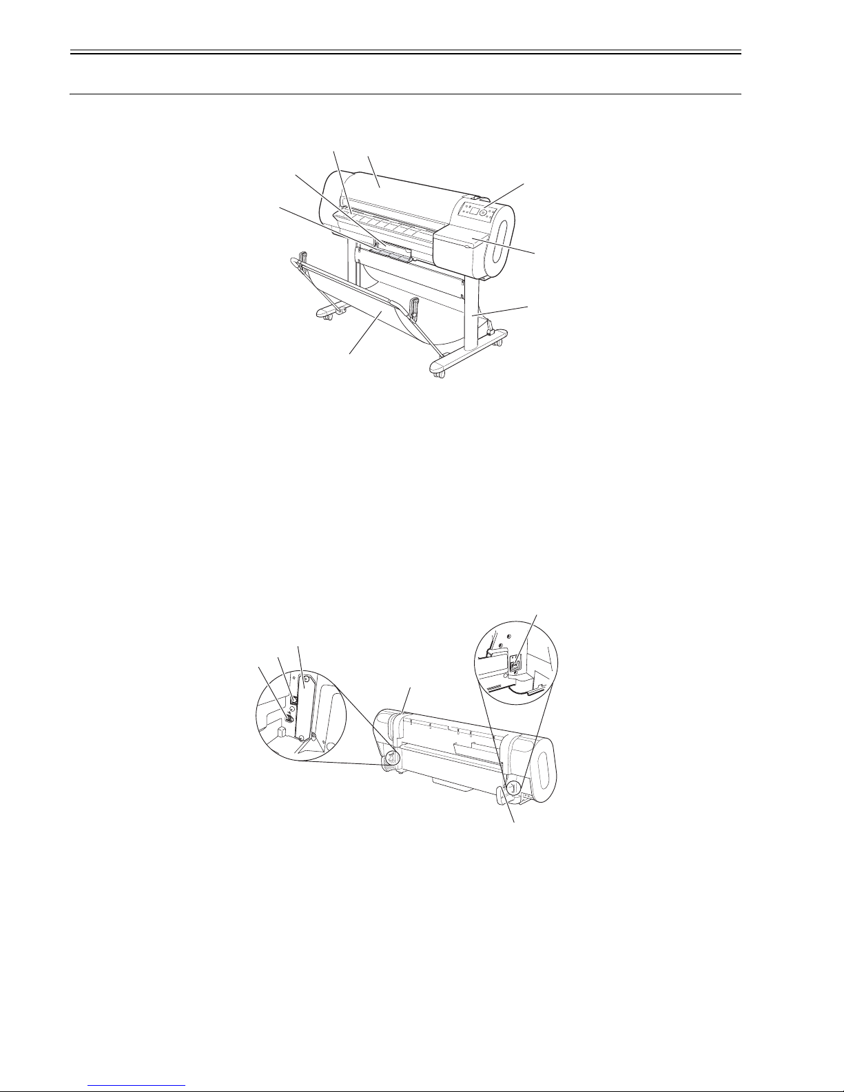
1.5 Names and Functions of Components
1.5.1 Printer front panel
0012-6202
F-1-11
[1] Top cover
Open this cover when installing the printhead, load media and clear jams inside the printer.
[2] Eject guide
Supports ejected media to keep it from floating up.
[3] Maintenance cartridge
Blots excess inks.
[4] Maintenance cartridge cover
Open this cover to replace the maintenance cartridge.
[5] Operation panel
Operate the printer or check its status from this panel.
[6] Ink tank cover
Open this cover to replace ink tanks.
[7] Stand (option)
It is a stand that puts the printer.
[8] Output stacker (included with stand)
It is a stacker made of the cloth that stacks the ejected media.
1.5.2 Printer rear panel
0013-4638
F-1-12
[1] Release lever
Releases the paper retainer. Press this lever rearward to load paper or clean the interiors of the printer.
[2] Power connector
Connect the power cord to this connector.
[3] Roller holder slot
Set the roll holder in this guide slot.
[4] Expansion PCB slot
Mount an IEEE1394 (Fire Wire) expansion PCB on his slot.
[5] USB port
Connect the USB cable to this port. Ready for the USB2.0 hi-speed mode.
[6] Ethernet connector
Connect the Ethernet cable to this connector.
[2]
[1]
[3]
[8]
[5]
[4]
[7]
[6]
[4]
[5]
[6]
[3]
[2]
[1]
Chapter 1
1-9
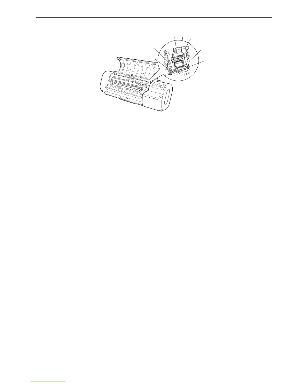
1.5.3 Carriage
0013-4655
F-1-13
[1] Carriage cover
Protects the carriage.
[2] Printhead fixer cover
Clamps the printhead.
[3] Printhead
A key component that houses nozzles.
[4] Shaft cleaner
Keeps the carriage shaft clean.
[5] Printhead fixer lever
Locks the printhead fixer cover.
[6] Slant adjustment lever
Fine-adjusts slants in ruled lines during printing.
[7] Cutter unit
A curved cutting edge that cuts paper automatically. It is tucked inside when cutting is not performed.
[1]
[2]
[3]
[4]
[5]
[6]
[7]
Chapter 1
1-10
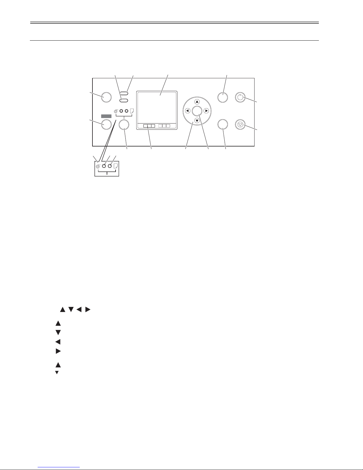
1.6 Basic Operation
1.6.1 Operation panel
0012-6207
The functions of the keys and meanings of LED indications on the operation panel are described below.
F-1-14
[1] Display
Displays the printer menu, status or messages.
[2] Data lamp (green)
"Blinking" The printer is receiving or processing a print job when it is printing.
The printer has suspended a print job or is receiving firmware data when it is not printing.
"Off" No print job is available.
[3] Message lamp (orange)
"Lit continuously" A warning message is on display.
"Blinking" An error message is on display.
"Off" The printer is normal or is powered off.
[4] Online key
Switches the printer between two alternative modes: online and offline.
"Lit continuously" The printer is in online mode. Lights green.
"Off" The printer is in offline mode.
[5] Menu key
Displays a printer main menu.
[6] Paper source selector
[a] Roll media lamp (green)
"Lit continuously" Roll media have been selected as a paper source.
"Off" Cut media have been selected as a paper source.
[b] Cut media lamp (green)
"Lit continuously" Cut media have been selected as a paper source.
"Off" Roll media have been selected as a paper source.
[7] Paper source selector key
Toggles a paper source between roll and cut media each time the key is pressed.
[8] Color labels
Colors and names of ink tanks associated with the remaining ink levels appearing on the display.
[9] Keys
[Menu mode]
" key" Displays the previous action or setting.
" key" Displays the next action or setting.
" key" Opens the menu one level above.
" key" Opens the menu one level lower.
[Offline mode]
" key" Feeds roll media manually in the direction opposite to the direction in which paper is ejected.
" key" Feeds roll media manually.
[10] OK key
Sets or runs a selected action or value when the printer is in menu mode.
[11] eject key
Executing menu and ejects paper.
[12] Stop key
Quits a processing job.
[13] Power key
Switches the power to the printer on and off.
[14] Information key
Displays a printer submenu. Information about the inks and paper displays each time this key is pressed.
Hold this key for 3 seconds to clean the printhead.
OK
Online
Menu
Data
Message
Infomation
Powe r
Eject
Stop
Cleaning
(3 Sec.)
[4]
[5]
[3] [2]
[7] [8]
[1]
[9] [10]
[14]
[11]
[13]
[12]
[6]
[a]
[b]
Chapter 1
1-11
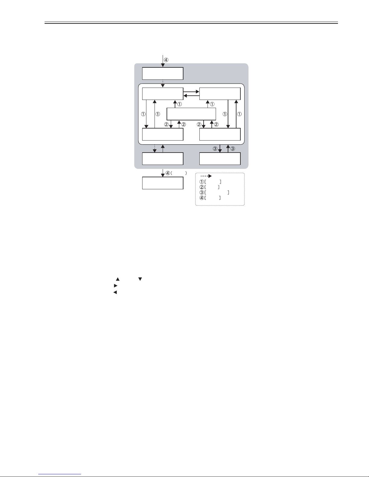
1.6.2 Printer state transitions
0013-5388
The different states of the printer and their transitions caused by pressing the relevant keys are shown below.
F-1-15
1.6.3 Main menu
0012-6209
This printer supports a main menu that offers an organized clue to opening a maintenance menu for adjusting the discharge position of each nozzle, cleaning the
printhead and so on, a print setup menu for setting the auto-cutting feature, the ink drying time and so on, a parameters menu for selecting a message display language
and so on, and more..
a. Working with the main menu
(1) How to enter the main menu
While the printer is in offline mode, press the [Menu] key to enter the main menu.
(2) How to exit the main menu
To exit the main menu, press the [Online] key.
(3) Functions of keys on the main menu
-To select menu choices and settings: [ ] key or [ ] key
-To enter the menu one level below: [ ] key
-To enter the menu one level above: [ ] key
-To accept menu choices or settings: [OK] key
ONLINE PRINTING
MAIN MENU
OFFLINE
SLEEP SUB MENU
INITIALIZING
1 Sec.
PAUSE
SHUTDOWN
Auto
Key operations
and print commands
Online Key
Menu Key
Infomation Key
Powe r Key

Chapter 1
1-12
b. Main menu List
The hierarchy and settings of the main menus are described below.
F-1-16
MAIN MENU
Force Cutting
No
Yes
Rep.Ink Tank
No
Yes
Head Cleaning
Media Menu
Roll Media Type
(Select media type)
Chk Remain.Roll
On
Off
Roll Length Set
### m / ### ft
* Displayed only when "On" is selected for "Chk Remain,Roll"
Cut Sheet Type
(Select media type)
Paper Deteils
(Select media type) Refer to "Media detail setup menu"
Adjust Printer Refer to "Printing adjustment menu"
Interface Setup Refer to "Interface setup menu"
Maintenance
Repl.Maint.C
No
Yes
Replace P.head
Repl.S.Cleaner
No
Yes
Change Cutter
No
Yes
Move Printer
No
Yes
System Setup Refer to "System setup menu"
"Test Print"
Status Print
Media Details
Print Job Log
Menu Map
Nozzle Check
Information Refer to "Information menu"
No
Yes
Head Cleaning A
Head Cleaning B

Chapter 1
1-13
F-1-17
Paper Details MENU
Paper Details
Drying_Time
Off
(30sec. 1min. 3min. 5min. 10min. 30min.)
60min.
Scan Wait Time
Off
(1sec. 3sec. 5sec. 7sec.)
9sec.
Feed Priority
Automatic
Band Joint
Print Length
Head Height
Automatic
(Lowest Low Standard High)
Highest
Skew Check Lv.
Standard
Off
Loose
VacuumStrngth
Automatic
Strongest
Standard
Weak
Width Detection
On
Off
NearEnd Rllmrgn
3mm
20mm
Cut Speed
Fast
Standard
Slow
Trim Edge First
Forced
No Cutting
Cutting Mode
Automaric
Eject
Manual
Bordless Margin
Automatic
Fixed
CutDustReduct.
On
Off
Nr End Sht Mrgn
3mm
20mm
Return Defaults
No
Yes
Print Length
-0.70%
0.70%
Strong
Auto cut

Chapter 1
1-14
F-1-18
Adjust Printer Menu
Adjust Printer
Auto Head Adj.
Standard Adj.
No
Yes
Advanced Adj.
No
Yes
Auto Print
On
Off
Manual Head Adj
No
Yes
Auto Band Adj.
Standard Adj.
No
Yes
Advanced Adj.
No
Yes
Manual Band Adj
Adjust Band
No
Yes
Adjust Length
No
Yes
Head Inc.Adj.
No
Yes
 Loading...