


Service Manual
iPF680/670/650 series
iPF671
Dec 17 2014


Application
This manual has been issued by Canon Inc. for qualified persons to learn technical theory, installation, maintenance, and repair
of products. This manual covers all localities where the products are sold. For this reason, there may be information in this
manual that does not apply to your locality.
Corrections
This manual may contain technical inaccuracies or typographical errors due to improvements or changes in products. When
changes occur in applicable products or in the contents of this manual, Canon will release technical information as the need
arises. In the event of major changes in the contents of this manual over a long or short period, Canon will issue a new edition
of this manual.
The following paragraph does not apply to any countries where such provisions are inconsistent with local law.
Trademarks
The product names and company names used in this manual are the registered trademarks of the individual companies.
Copyright
This manual is copyrighted with all rights reserved. Under the copyright laws, this manual may not be copied, reproduced or
translated into another language, in whole or in part, without the written consent of Canon Inc.
COPYRIGHT © 2001 CANON INC.
Printed in Japan
Caution
Use of this manual should be strictly supervised to avoid disclosure of confidential information.

Symbols Used
This documentation uses the following symbols to indicate special information:
Symbol Description
Indicates an item of a non-specific nature, possibly classified as Note, Caution, or Warning.
Indicates an item requiring care to avoid electric shocks.
Indicates an item requiring care to avoid combustion (fire).
Indicates an item prohibiting disassembly to avoid electric shocks or problems.
Indicates an item requiring disconnection of the power plug from the electric outlet.
Indicates an item intended to provide notes assisting the understanding of the topic in question.
Memo
Introduction
REF.
Indicates an item of reference assisting the understanding of the topic in question.
Provides a description of a service mode.
Provides a description of the nature of an error indication.

Introduction
The following rules apply throughout this Service Manual:
1. Each chapter contains sections explaining the purpose of specific functions and the relationship between electrical and mechanical systems with reference to the timing of operation.
In the diagrams, represents the path of mechanical drive; where a signal name accompanies the symbol , the arrow indicates the
direction of the electric signal.
The expression "turn on the power" means flipping on the power switch, closing the front door, and closing the delivery unit door, which results in
supplying the machine with power.
2. In the digital circuits, '1'is used to indicate that the voltage level of a given signal is "High", while '0' is used to indicate "Low".(The voltage value, however, differs from circuit to circuit.) In addition, the asterisk (*) as in "DRMD*" indicates that the DRMD signal goes on when '0'.
In practically all cases, the internal mechanisms of a microprocessor cannot be checked in the field. Therefore, the operations of the microprocessors
used in the machines are not discussed: they are explained in terms of from sensors to the input of the DC controller PCB and from the output of the
DC controller PCB to the loads.
The descriptions in this Service Manual are subject to change without notice for product improvement or other purposes, and major changes will be communicated in the form of Service Information bulletins.
All service persons are expected to have a good understanding of the contents of this Service Manual and all relevant Service Information bulletins and be
able to identify and isolate faults in the machine."


Contents
Contents
Chapter 1 PRODUCT DESCRIPTION
1.1 Product Overview ....................................................................................................................................... 1- 1
1.1.1 Product Overview ....................................................................................................................................................1- 1
1.2 Features ..................................................................................................................................................... 1- 2
1.2.1 Features ..................................................................................................................................................................1- 2
1.2.2 Printhead .................................................................................................................................................................1- 2
1.2.3 Ink Tank...................................................................................................................................................................1- 2
1.2.4 Cutter.......................................................................................................................................................................1- 2
1.2.5 Roll Holder............................................................................................................................................................... 1- 2
1.2.6 Stand (ST-26) ..........................................................................................................................................................1- 4
1.2.7 Stand (ST-27) ..........................................................................................................................................................1- 6
1.2.8 Consumables...........................................................................................................................................................1- 9
1.3 Product Specifications ..............................................................................................................................1- 10
1.3.1 Product Specifications ...........................................................................................................................................1- 10
1.4 Detailed Specifications ............................................................................................................................. 1- 11
1.4.1 Interface Specifications .........................................................................................................................................1- 11
1.5 Names and Functions of Components ..................................................................................................... 1- 13
1.5.1 Front ......................................................................................................................................................................1- 13
1.5.2 Side .......................................................................................................................................................................1- 14
1.5.3 Top Cover (Inside).................................................................................................................................................1- 15
1.5.4 Roll Unit Cover (Inside) .........................................................................................................................................1- 16
1.5.5 Carriage.................................................................................................................................................................1- 16
1.5.6 Ink Tank Cover (Inside) .........................................................................................................................................1- 17
1.5.7 Stand (ST-26) ........................................................................................................................................................1- 18
1.5.8 Stand (ST-27) ........................................................................................................................................................1- 19
1.6 Basic Operation ........................................................................................................................................ 1- 20
1.6.1 Operation Panel.....................................................................................................................................................1- 20
1.6.2 Display...................................................................................................................................................................1- 21
1.6.3 Menu......................................................................................................................................................................1- 22
1.7 Safety and Precautions ............................................................................................................................1- 42
1.7.1 Safety Precautions ................................................................................................................................................1- 42
1.7.1.1 Moving Parts .......................................................................................................................................................................... 1- 42
1.7.1.2 Adhesion of Ink ...................................................................................................................................................................... 1- 43
1.7.1.3 Electric Parts.......................................................................................................................................................................... 1- 44
1.7.2 Other Precautions..................................................................................................................................................1- 45
1.7.2.1 Printhead................................................................................................................................................................................ 1- 45
1.7.2.2 Ink Tank ................................................................................................................................................................................. 1- 46
1.7.2.3 Handling the Printer ............................................................................................................................................................... 1- 46
1.7.3 Precautions When Servicing Printer......................................................................................................................1- 48
1.7.3.1 Notes on the Data Stored in the Printer ................................................................................................................................. 1- 48
1.7.3.2 Confirming the Firmware Version .......................................................................................................................................... 1- 48
1.7.3.3 Precautions against Static Electricity ..................................................................................................................................... 1- 48
1.7.3.4 Precautions for Disassembly/Reassembly............................................................................................................................. 1- 48
1.7.3.5 Self-diagnostic Feature .......................................................................................................................................................... 1- 48
1.7.3.6 Disposing of the Lithium Battery ............................................................................................................................................ 1- 49
Chapter 2 TECHNICAL REFERENCE
2.1 Basic Operation Outline..............................................................................................................................2- 1
2.1.1 Printer Diagram .......................................................................................................................................................2- 1
2.1.2 Print Signal Sequence .............................................................................................................................................2- 2

Contents
2.1.3 Print Driving .............................................................................................................................................................2- 3
2.2 Firmware .................................................................................................................................................... 2- 5
2.2.1 Operation Sequence at Power-on............................................................................................................................2- 5
2.2.2 Operation Sequence at Power-off............................................................................................................................2- 6
2.2.3 Print Position Adjustment Function ..........................................................................................................................2- 7
2.2.4 Head Management ..................................................................................................................................................2- 7
2.2.5 Printhead Overheating Protection Control ...............................................................................................................2- 7
2.2.6 Pause between Pages.............................................................................................................................................2- 7
2.2.7 White Raster Skip ....................................................................................................................................................2- 7
2.2.8 Sleep Mode..............................................................................................................................................................2- 7
2.2.9 Shut Down Mode .....................................................................................................................................................2- 7
2.3 Printer Mechanical System......................................................................................................................... 2- 8
2.3.1 Outline......................................................................................................................................................................2- 8
2.3.1.1 Outline...................................................................................................................................................................................... 2- 8
2.3.2 Ink Passage .............................................................................................................................................................2- 9
2.3.2.1 Ink Passage ............................................................................................................................................................................. 2- 9
2.3.2.2 Ink Tank Unit .......................................................................................................................................................................... 2- 10
2.3.2.3 Carriage Unit .......................................................................................................................................................................... 2- 12
2.3.2.4 Printhead................................................................................................................................................................................ 2- 16
2.3.2.5 Purge Unit .............................................................................................................................................................................. 2- 17
2.3.2.6 Maintenance Cartridge........................................................................................................................................................... 2- 22
2.3.2.7 Air Flow .................................................................................................................................................................................. 2- 23
2.3.3 Paper Path.............................................................................................................................................................2- 25
2.3.3.1 Outline.................................................................................................................................................................................... 2- 25
2.3.3.2 Paper Path ............................................................................................................................................................................. 2- 26
2.3.3.3 Cutter Unit .............................................................................................................................................................................. 2- 28
2.4 Printer Electrical System .......................................................................................................................... 2- 29
2.4.1 Outline....................................................................................................................................................................2- 29
2.4.1.1 Overview ................................................................................................................................................................................ 2- 29
2.4.2 Main Controller.......................................................................................................................................................2- 31
2.4.2.1 Main controller PCB components .......................................................................................................................................... 2- 31
2.4.2.2 Connectors and Pin Arrangement of Main controller PCB..................................................................................................... 2- 32
2.4.3 Carriage Relay PCB...............................................................................................................................................2- 39
2.4.3.1 Carriage PCB components .................................................................................................................................................... 2- 39
2.4.3.2 Connectors and Pin Arrangement of Carriage PCB .............................................................................................................. 2- 40
2.4.4 Maintenance Cartridge Relay PCB ........................................................................................................................2- 44
2.4.4.1 Maintenance cartridge relay PCB components...................................................................................................................... 2- 44
2.4.5 Power Supply.........................................................................................................................................................2- 45
2.4.5.1 Power supply block diagram .................................................................................................................................................. 2- 45
2.4.5.2 Connectors and Pin Arrangement of Power supply PCB....................................................................................................... 2- 46
2.5 Detection Functions with Sensors ............................................................................................................ 2- 47
2.5.1 Covers....................................................................................................................................................................2- 47
2.5.2 Ink passage system ...............................................................................................................................................2- 48
2.5.3 Carriage system.....................................................................................................................................................2- 51
2.5.4 Paper path system.................................................................................................................................................2- 53
2.5.5 Others ....................................................................................................................................................................2- 55
Chapter 3 INSTALLATION
3.1 Transporting the Printer.............................................................................................................................. 3- 1
3.1.1 Transporting the Printer ...........................................................................................................................................3- 1
3.1.1.1 Transporting the Printer ........................................................................................................................................................... 3- 1
3.1.2 Reinstalling the Printer.............................................................................................................................................3- 4
3.1.2.1 Reinstalling the Printer ............................................................................................................................................................. 3- 4
Chapter 4 DISASSEMBLY/REASSEMBLY
4.1 Service Parts .............................................................................................................................................. 4- 1

Contents
4.1.1 Service Parts ...........................................................................................................................................................4- 1
4.2 Disassembly/Reassembly...........................................................................................................................4- 2
4.2.1 Disassembly/Reassembly ....................................................................................................................................... 4- 2
4.3 Points to Note on Disassembly and Reassembly .......................................................................................4- 2
4.3.1 Note: Items that should never be disassembled......................................................................................................4- 2
4.3.2 Moving the carriage manually.................................................................................................................................. 4- 2
4.3.3 Units requiring draining of ink ..................................................................................................................................4- 3
4.3.4 External Covers .......................................................................................................................................................4- 4
4.3.5 Drive Unit............................................................................................................................................................... 4- 13
4.3.6 Cutter.....................................................................................................................................................................4- 17
4.3.7 Carriage Unit .........................................................................................................................................................4- 19
4.3.8 Purge Unit..............................................................................................................................................................4- 26
4.3.9 Ink Tank Unit .........................................................................................................................................................4- 30
4.3.10 Ink Tube Unit .......................................................................................................................................................4- 33
4.3.11 Waste Ink Collection Unit.....................................................................................................................................4- 37
4.3.12 Multi Sensor.........................................................................................................................................................4- 42
4.3.13 Linear Encoder .................................................................................................................................................... 4- 43
4.3.14 Head Management Sensor..................................................................................................................................4- 48
4.3.15 PCBs....................................................................................................................................................................4- 49
4.3.16 Opening the Cap/Moving the Wiper Unit .............................................................................................................4- 50
4.3.17 Opening/Closing the Ink Supply Valve/Subtank Air Passage Valve ....................................................................4- 52
4.3.18 Draining the ink....................................................................................................................................................4- 53
4.4 Applying the Grease .................................................................................................................................4- 54
4.4.1 Applying the Grease ..............................................................................................................................................4- 54
4.5 Adjustment and Setup Items ....................................................................................................................4- 58
4.5.1 Adjustment Item List ..............................................................................................................................................4- 58
4.5.2 Procedure after Replacing the Carriage Unit or Multi Sensor ...............................................................................4- 58
4.5.3 Procedure after Replacing the Feed Roller or Feed Roller Encoder .....................................................................4- 58
4.5.4 Procedure after Replacing the Head Management Sensor ...................................................................................4- 58
Chapter 5 MAINTENANCE
5.1 Periodic Replacement Parts ....................................................................................................................... 5- 1
5.1.1 Periodic Replacement Parts ....................................................................................................................................5- 1
5.2 Consumable Parts ......................................................................................................................................5- 1
5.2.1 Consumable Parts ...................................................................................................................................................5- 1
5.3 Periodic Maintenance .................................................................................................................................5- 3
5.3.1 Periodic Maintenance ..............................................................................................................................................5- 3
Chapter 6 TROUBLESHOOTING
6.1 Troubleshooting..........................................................................................................................................6- 1
6.1.1 Outline .....................................................................................................................................................................6- 1
6.1.1.1 Outline of Troubleshooting ....................................................................................................................................................... 6- 1
6.2 Error Code .................................................................................................................................................. 6- 2
6.2.1 Outline .....................................................................................................................................................................6- 2
6.2.1.1 Outline...................................................................................................................................................................................... 6- 2
6.2.2 Warning/Error/Service Call Error .............................................................................................................................6- 3
6.2.2.1 Code Table .............................................................................................................................................................................. 6- 3
6.3 Service Software ...................................................................................................................................... 6- 35
6.3.1 L Printer Service Tool ............................................................................................................................................6- 35
6.4 Firmware Update Tool ..............................................................................................................................6- 39
6.4.1 imagePROGRAF Firmware Update Tool ..............................................................................................................6- 39
6.5 Service Tools ............................................................................................................................................6- 41
6.5.1 Tool List .................................................................................................................................................................6- 41

Contents
Chapter 7 SERVICE MODE
7.1 Service Mode ............................................................................................................................................. 7- 1
7.1.1 Service Mode Operation ..........................................................................................................................................7- 1
7.1.2 Map of the Service Mode.........................................................................................................................................7- 2
7.1.3 Details of Service Mode.........................................................................................................................................7- 10
7.1.4 e-Maintenance/imageWARE Remote....................................................................................................................7- 28
7.1.5 Viewing PRINT INF................................................................................................................................................7- 38
7.2 Special Mode............................................................................................................................................ 7- 53
7.2.1 Special Modes for Servicing ..................................................................................................................................7- 53

Chapter 1 PRODUCT DESCRIPTION


Contents
Contents
1.1 Product Overview ..........................................................................................................................................................1-1
1.1.1 Product Overview ........................................................................................................................................................................ 1-1
1.2 Features ..........................................................................................................................................................................1-2
1.2.1 Features ........................................................................................................................................................................................ 1-2
1.2.2 Printhead ...................................................................................................................................................................................... 1-2
1.2.3 Ink Tank ....................................................................................................................................................................................... 1-2
1.2.4 Cutter............................................................................................................................................................................................ 1-2
1.2.5 Roll Holder................................................................................................................................................................................... 1-2
1.2.6 Stand (ST-26)............................................................................................................................................................................... 1-4
1.2.7 Stand (ST-27)............................................................................................................................................................................... 1-6
1.2.8 Consumables ................................................................................................................................................................................ 1-9
1.3 Product Specifications..................................................................................................................................................1-10
1.3.1 Product Specifications ............................................................................................................................................................... 1-10
1.4 Detailed Specifications ................................................................................................................................................1-11
1.4.1 Interface Specifications .............................................................................................................................................................. 1-11
1.5 Names and Functions of Components .........................................................................................................................1-13
1.5.1 Front ........................................................................................................................................................................................... 1-13
1.5.2 Side ............................................................................................................................................................................................ 1-14
1.5.3 Top Cover (Inside) ..................................................................................................................................................................... 1-15
1.5.4 Roll Unit Cover (Inside) ............................................................................................................................................................ 1-16
1.5.5 Carriage...................................................................................................................................................................................... 1-16
1.5.6 Ink Tank Cover (Inside)............................................................................................................................................................. 1-17
1.5.7 Stand (ST-26)............................................................................................................................................................................. 1-18
1.5.8 Stand (ST-27)............................................................................................................................................................................. 1-19
1.6 Basic Operation............................................................................................................................................................1-20
1.6.1 Operation Panel.......................................................................................................................................................................... 1-20
1.6.2 Display ....................................................................................................................................................................................... 1-21
1.6.3 Menu .......................................................................................................................................................................................... 1-22
1.7 Safety and Precautions.................................................................................................................................................1-42
1.7.1 Safety Precautions...................................................................................................................................................................... 1-42
1.7.1.1 Moving Parts ................................................................................................................................................................................................. 1-42
1.7.1.2 Adhesion of Ink .............................................................................................................................................................................................1-43
1.7.1.3 Electric Parts .................................................................................................................................................................................................1-44
1.7.2 Other Precautions ....................................................................................................................................................................... 1-45
1.7.2.1 Printhead ....................................................................................................................................................................................................... 1-45
1.7.2.2 Ink Tank ........................................................................................................................................................................................................1-46
1.7.2.3 Handling the Printer ...................................................................................................................................................................................... 1-46
1.7.3 Precautions When Servicing Printer .......................................................................................................................................... 1-48
1.7.3.1 Notes on the Data Stored in the Printer.........................................................................................................................................................1-48
1.7.3.2 Confirming the Firmware Version ................................................................................................................................................................1-48
1.7.3.3 Precautions against Static Electricity ............................................................................................................................................................1-48
1.7.3.4 Precautions for Disassembly/Reassembly.....................................................................................................................................................1-48
1.7.3.5 Self-diagnostic Feature..................................................................................................................................................................................1-48
1.7.3.6 Disposing of the Lithium Battery.................................................................................................................................................................. 1-49

1.1 Product Overview
Chapter 1
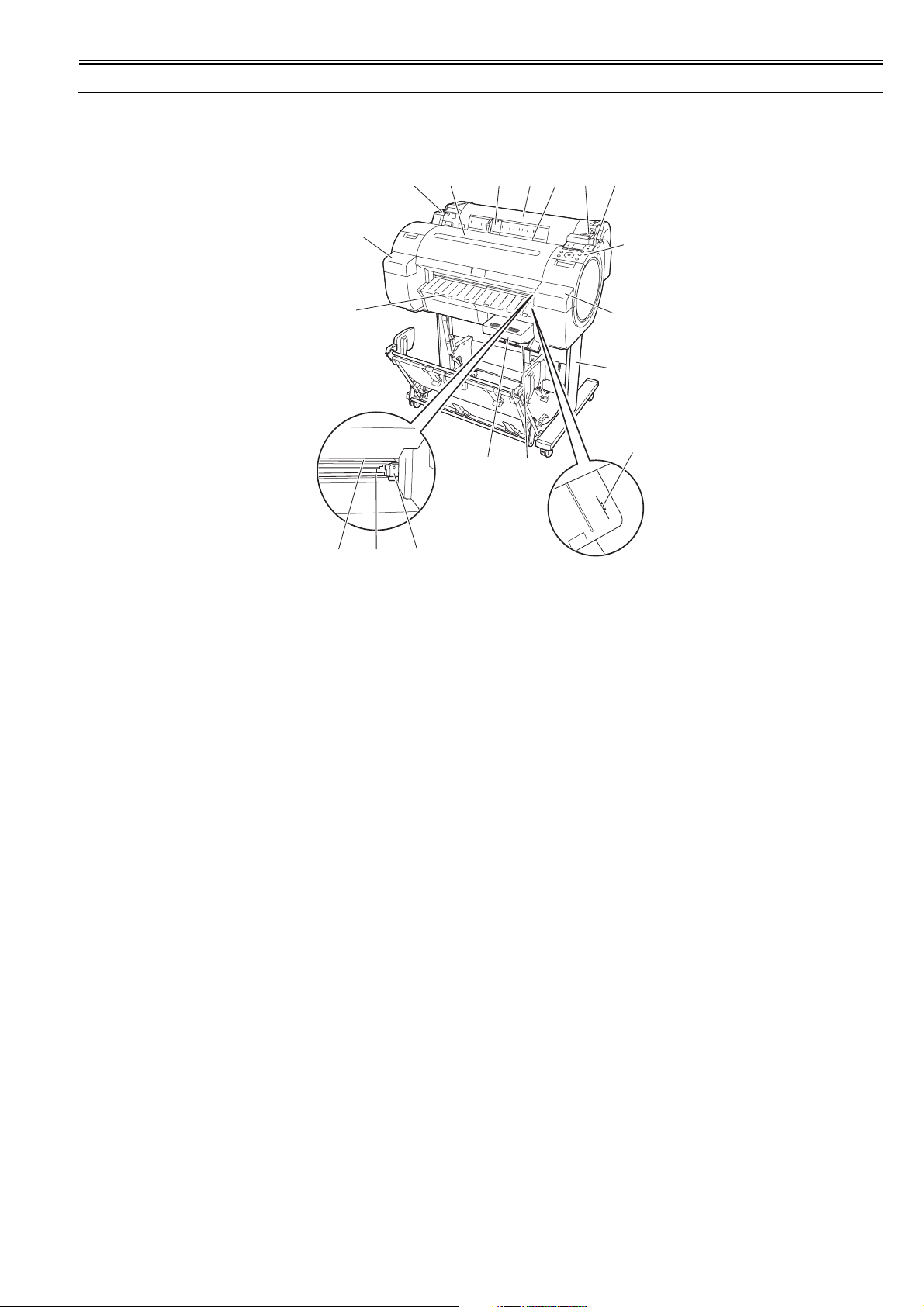
1.1.1 Product Overview
This printer is capable of printing on A4- to A1-size cut sheets and its maximum print width is 24 inches. This printer is a desktop large-format printer five-colors
(dye- and pigment-based colors) printer that can be used to print CAD and office documents as well as handy POP and posters.
[13]
[3]
[14]
[6]
[10]
[11][12]
[9]
F-1-1
[15]
[2] [3] [4]
[1]
[8]
[5]
[6]
[16]
[7]
0023-5225
[1] Roll media cover [9] Maintenance cartridge
[2] Media loading slot [10] Cutter unit
[3] Roll media temporary table [11] Cutter rail
[4] Release lever [12] Paper eject slot
[5] Operation panel [13] Output guide
[6] Ink tank cover [14] Upper cover
[7] Media alignment line [15] Width guide
[8] Maintenance cartridge cover [16] Stand
1-1
Chapter 1
1.2 Features
1.2.1 Features
- High resolutions of 2,400 x 1,200 dpi maximum, coupled with the exceptionally light-fast, water-proof and ozone-proof five-color pigment inks of Y, M, C, PBK
and MBK, deliver high-quality photographic picture quality.
- Black ink suitable for the selected media type is automatically selected from two types of black ink, "black ink" for vivid and glossy printing and "matte black
ink" for matte and high-quality printing.
- A 160-by-128-dot-large LCD
- One-inch wide printhead having 2,560 nozzles per color, which are as many as the those of the existing models. High-density printhead technology "FINE" that
can satisfy both of beautiful and fast printing requirements of a high order is employed for accurate ejection of ultrasmall 4-pl drops of ink to the target positions.
Prints with 2,400 x 1,200 dpi resolution can be made at a high speed.
- Imaging processor "L-COA" incorporated for high-speed image data processing. High-speed processing of 5-color, 12-bit large-size images and printer control
for high-accuracy operation of high-density head can be performed with a single chip.
- Standard support for 10Base-T/100Base-TX/1000Base-T and USB 2.0 Hi-Speed.
- Borderless printing on and auto cutting of roll media.
- All operations such as loading the roll media and cut sheet and replacing the ink tank can be carried out at the front (top) of the printer.
- The printer can be installed with its back in touch with the wall, requiring no installation space at the back of the printer.
- A subtank mounted at the ink port allows you to replace the ink tank during printing.
- The pressure of suction from the borderless printing ink catch groove changes automatically with the media size, preventing shift of media edges and staining of
the backside of the media.
- A printhead having nozzles (I-shaped nozzle) with a new shape reduces ink mist, ensuring superfine printing.
- Compatibility with e-maintenance/imageWARE Remote allows centralized management of customers' printer information.
0028-0098
- The newly designed operation panel allows you to operate the printer intuitively.
Functional enhancements new to this model include:
- The processing ability of the printed data will enhance by improvement of throughput.
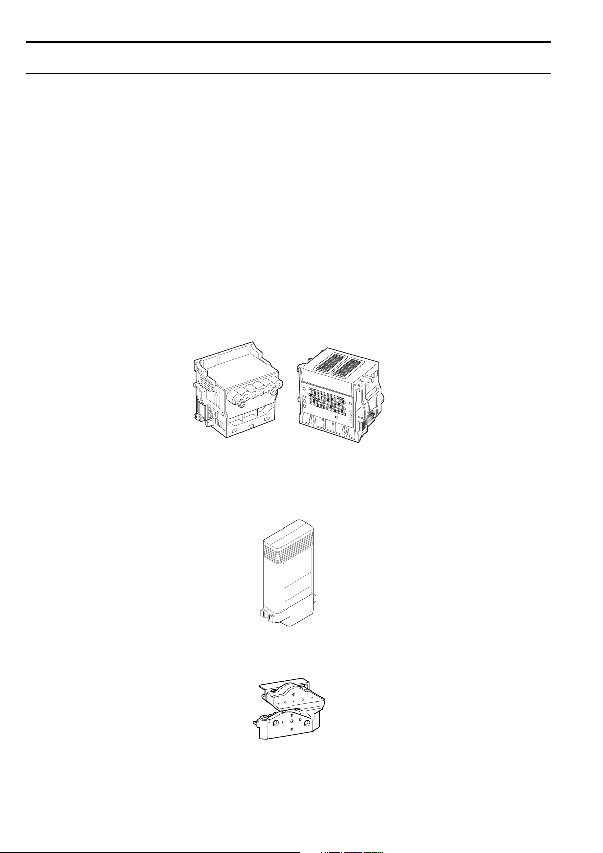
1.2.2 Printhead
The printhead that mounts on the carriage is an integrated six-color disposable printhead.
It has 5,120 nozzles for MBK and 2,560 nozzles for each additional color arranged in a staggered pattern.
0013-2741
If print quality remains unimproved even after a specified cleaning operation, replace the printhead.
F-1-2
1.2.3 Ink Tank
The ink tank is disposable.
There are four dye-based ink colors (black, cyan, magenta, and yellow) and one pigment-based ink color (matte black).
This printer features a mechanism by which only the correct color ink tank will fit in the given slot.
When the message that ink tank is empty is displayed, replace the ink tank with a new one.
F-1-3
1.2.4 Cutter
The cutter attached to the cutter unit is a round cutter.
0012-6188
0023-1309
1-2
F-1-4
Chapter 1
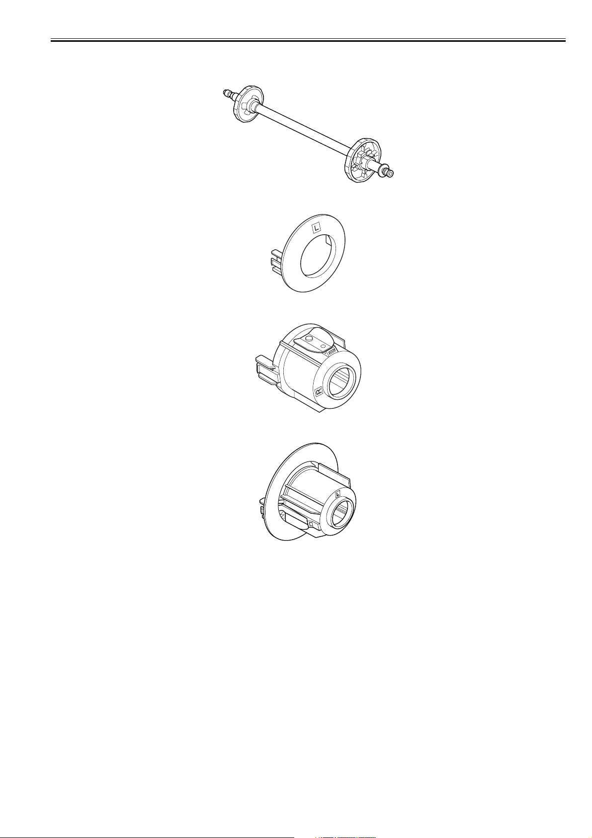
1.2.5 Roll Holder
The roller holder accepts paper tubes having inside diameters of both 2 and 3 inches. It is furnished with attachments for 2- and 3-inch diameter paper tubes.
The roll holder clamps the paper tube of a roll not exceeding 150 mm in outside diameter from the inside.
F-1-5
[2-inch paper tube attachment]
F-1-6
[3-inch paper tube attachment R]
0023-1308
[3-inch paper tube attachment L]
F-1-7
F-1-8
1-3
Chapter 1
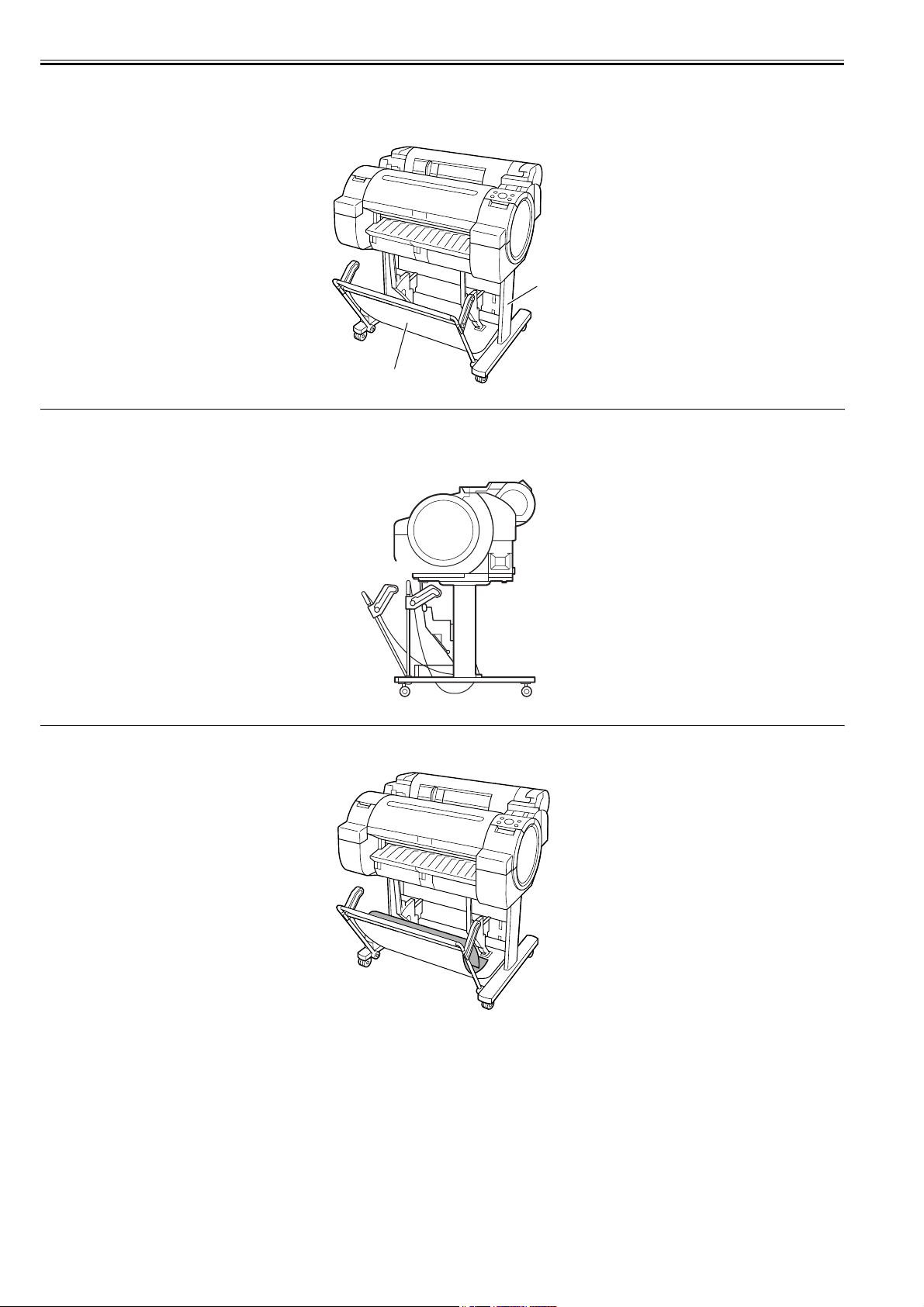
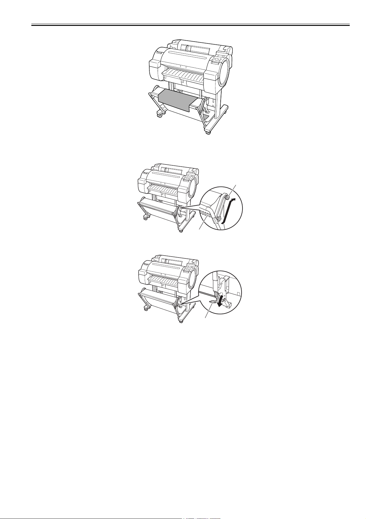
1.2.6 Stand (ST-26)
The stand [1] is equipped with casters so that the printer can be easily moved. The output stacker [2] included with stand can use by the two ways of the regular
position or extended position.
0023-5227
[1]
[2]
F-1-9
MEMO:
- When delivering the printing to the output stacker: Use the position [A].
- When not using the output stacker or moving the printer: Use the position [B]. When moving the printer, raise the auxiliary rod to the position of extended position.
The output stacker may touch the floor and be soiled or damaged.
[Regular position]
[A]
[B]
F-1-10
F-1-11
1-4
[Extended position]
F-1-12
- Changing from the regular position to extended position.
1) Raise the auxiliary rod [1] to the position [A] of the illustration to change to the extended position.
Chapter 1
[A]
[1]
F-1-13
2) Pull out the switching stopper [1] when using roll paper that is A1 size or has a width of 24 inches.
[1]
F-1-14
1-5
Chapter 1
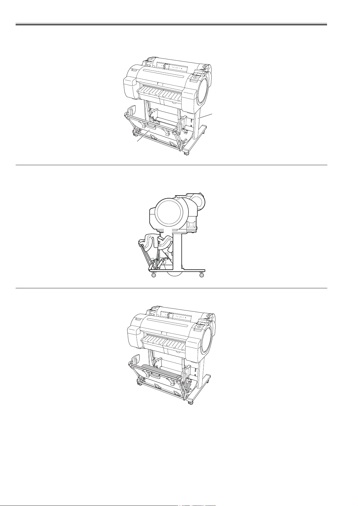
1.2.7 Stand (ST-27)
The stand [1] is equipped with casters so that the printer can be easily moved. The output stacker [2] included with stand can use by the three ways of the regular
position or two extended positions.
0027-2231
[1]
[2]
F-1-15
MEMO:
- When delivering the printing to the output stacker: Use the position [A].
- When not using the output stacker or moving the printer: Use the position [B]. When moving the printer, raise the auxiliary rod to the position of extended position.
The output stacker may touch the floor and be soiled or damaged.
[Regular position]
[A]
[B]
F-1-16
1-6
F-1-17
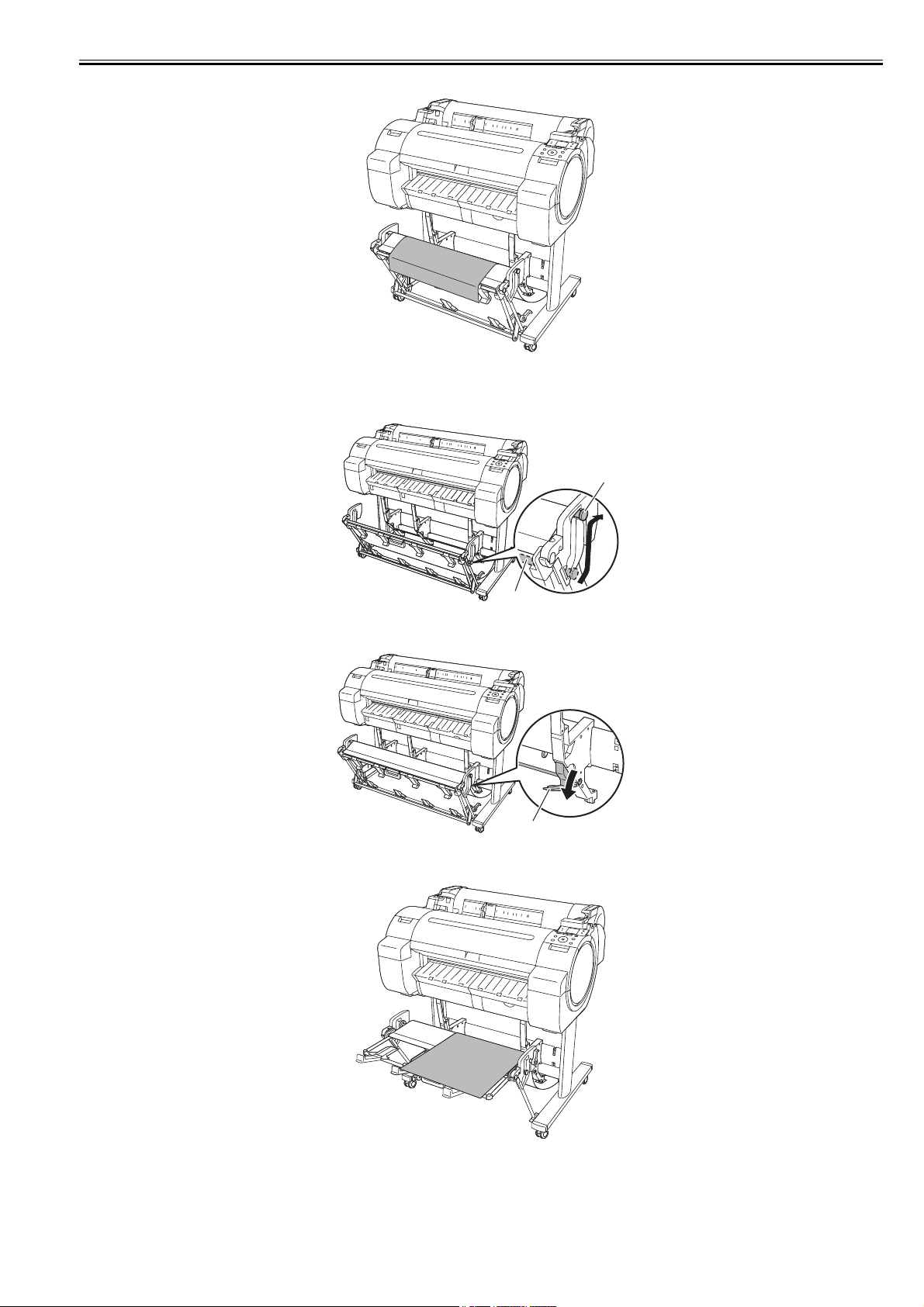
[Extended position A]
F-1-18
- Changing from the regular position to extended position A.
1) Raise the auxiliary rod [1] to the position [A] of the illustration to change to the extended position A.
Chapter 1
[A]
[1]
F-1-19
2) Pull out the switching stopper [1] when using roll paper that is A1 size or has a width of 24 inches.
[1]
F-1-20
[Extended position B]
F-1-21
1-7
Chapter 1
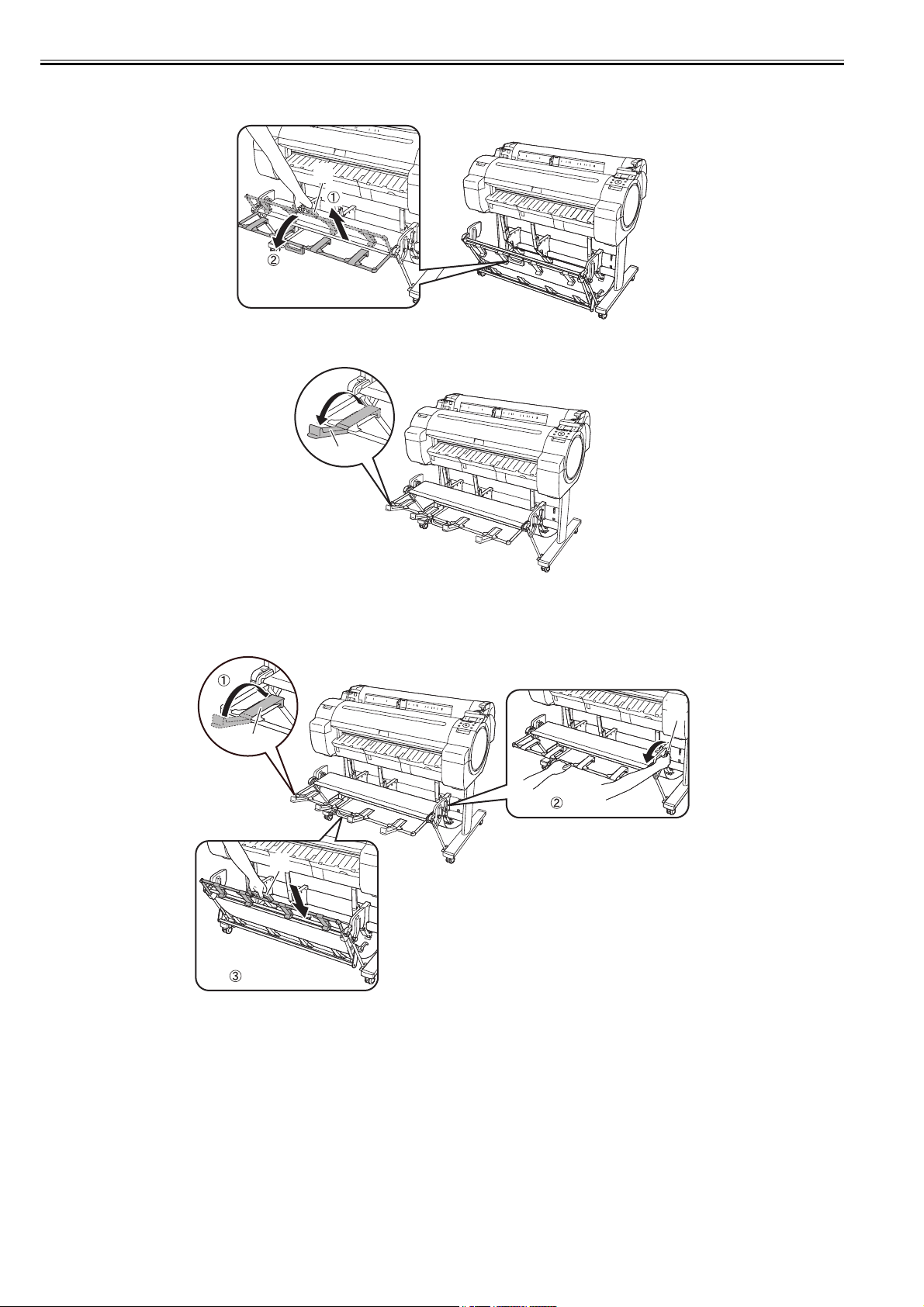
- Changing from the regular position to extended position B.
1) Grasp the output stacker handle [1] to set the guide as shown in the following illustration.
[1]
F-1-22
2) Open the output stacker ejection guides [1] toward the front.
[1]
F-1-23
- Changing from the extended position B to regular position.
1) Close the output stacker ejection guides [1] and pull the output stacker release lever [2] forward to release the lock, and then grasp the output stacker handle [3]
to return the guide.
[2]
[1]
[3]
F-1-24
1-8
Chapter 1
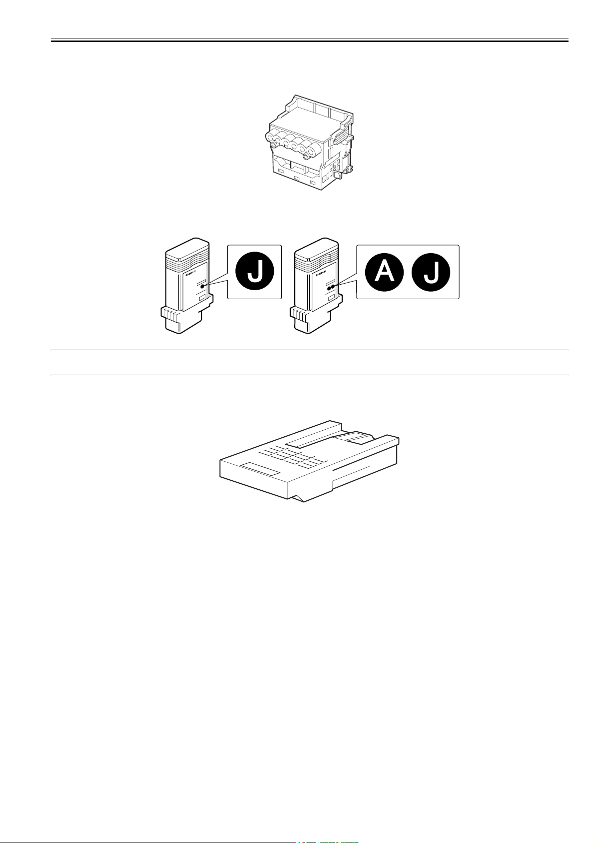
1.2.8 Consumables
Printhead
The consumable printhead is the same as that supplied with the printer.
F-1-25
Ink Tanks
The consumable ink tanks are available in five colors (matte black, black, cyan, magenta and yellow). They are the same as those supplied with the printer.
The ink tank that can be used with this printer is labeled "J".
F-1-26
0023-1261
MEMO:
You can also use ink tanks other than magenta ink tank that are simply labeled "A".
Maintenance Cartridge
The consumable maintenance cartridge is the same as that supplied with the printer.
F-1-27
1-9

Chapter 1
1.3 Product Specifications
1.3.1 Product Specifications
Type Bubble jet large-sized paper printer (stand model)
Feeding system Roll media: manual feed from top
Feeding capacity - Roll media: 1 roll madia (Outer diameter of roll: 150 mm or less/Inner
Delivery method Forward delivery, face up
Sheet delivery capability Stacking to the output stacker of the stand
Cutter Automatic cross-cutter (round blade)
Type of media Roll Media:
Supported thickness 0.07mm to 0.8mm
Media size (Roll media) Width: 254.0mm (10") to 609.6mm (24")
Media size (Cut sheet) Width: 203.2mm (8") to 609.6mm (24")
Printable area (Roll media) Internal area, excluding a 3-mm top, bottom and left and right margins.
Printable area (Cut sheet) Internal area, excluding a 3-mm top margin, a 23-mm bottom margin and
Printing recommendation area
(Roll media)
Printing recommendation area
(Cut sheet)
Memory 256MB
Firmware Flash ROM (update from USB or Ethernet)
Interface USB2.0 Hi-Speed
Cut sheet: manual feed from top
diameter of paper tube: 2 or 3 inches)
- Cut sheet: 1 sheet
- 1 sheet: when using in the regular position
- approximate 20 sheets: when using in the extended position (However,
it has the following restrictions.)
when using in the extended position/extended position A: paper length
A0/36"X48" or A1/24"X36" size plain paper or recycled paper
when using in the extended position B: paper length A1/36"X24" or A2/
24"X18" size plain paper or recycled paper
Plain Paper, Plain Paper (High Quality), Plain Paper (High Grade),
Coated Paper, Heavyweight Coated Paper, Premium Matte Paper,
Premium Glossy Paper 200, Premium Semi-Glossy Paper 200, Premium
Glossy Paper 280, Premium Semi-Glossy Paper 280, Back Light Film,
Economy Bond Paper, Universal Bond Paper, Matte Coated Paper
170gsm, Premium RC Photo Luster, Durable Backlit Film, High
Resolution Coated Paper, Matte Coated Paper 90gsm, Glossy
Photographic Paper 190gsm, Glossy Photographic Paper 240gsm, Satin
Photographic Paper 240gsm, Glossy Photographic Paper 270gsm, Satin
Photographic Paper 270gsm, HW Glossy Photo Paper, HW Satin Photo
Paper, Commercial Proofing Paper, Standard Paper1569B 80g, Standard
Paper1570B 90g, Matt Coated Paper 9171, Matt Coated Paper 7215,
Matt Coated Paper 140g, Opaque Paper White, Hi Res Graphic Paper, Hi
Res Barrier Paper, Photo Realistic Paper 210g, Photo paper Pearl 260g,
Glossy Proofing Paper 195g, Semiglossy Proofing Paper 195g,
Semiglossy Proofing Paper 255g
Cut Paper:
Plain Paper, Plain Paper (High Quality), Plain Paper (High Grade),
Coated Paper, Premiun Matte Paper, Premium Glossy Paper 280,
Premium Semi-Glossy Paper 280, High Resolution Paper, Matte Photo
Paper, Glossy Photo Paper GP-501, Photo Paper Plus Glossy 2, Photo
Paper Pro Platium, Photo Paper Plus Semi-Gloss, Universal Bond Paper,
Premium RC Photo Luster, High Resolution Coated Paper, Matt Coated
Paper 7215, Matt Coated Paper 140g
Length: 203.2mm (8") to 18m (709") *1
Outer diameter of roll :150mm or less
*1: The maximum amount of length may vary by the using operating
system or the applications.
Length: 279.4mm (11") to 1600mm (63") *1
*1: The maximum amount of length may vary by the using operating
system or the applications.
Borderless printing: 0 mm from the leading edge, trailing edge, and left
and right edges.
* The printable area may vary with each type of paper media used.
Width of media allowing borderless printing:
24"(609.6mm), A1(594.0mm), B2(515.0mm), 17"(431.8mm),
A2(420.0mm), 14"(355.6mm), 300mm, A3(297.0mm), B4(257.0mm),
10"(254mm)
3-mm left and right margins.
* The printable area may vary with each type of paper media used.
Internal area, excluding a 20-mm top margin, a 5-mm bottom margin and
5-mm left and right margins.
Internal area, excluding a 20-mm top margin, a 23-mm bottom margin
and 5-mm left and right margins.
Increase of memory: none
- Printer description language
GARO (Graphic Arts language with Raster Operation), HP-GL/2, HPRTL
Network (10Base-T/100Base-TX/1000Base-T)
0032-0487
1-10
Chapter 1
Operation panel LCD (160 X 128 dots), 13 keys, 5 LEDs
Printhead/Ink Tank type Printhead and separate ink tanks
Printhead PF-04
Ink tank [PFI-107/8107] MBK, BK, C, M, Y
Detection functions (Cover
system)
Detection functions (Ink passage
system)
Detection functions (Carriage
system)
Detection functions (Paper path
system)
Operating noise Operating: Approx. 47dB (A) or less
Operating environment Temperature: 15 to 30 degrees centigrade
Print quality guaranteed
environment
Power supply 100-240 VAC (50/60 Hz)
Power consumption (Maximum) During printing: Max. 140 W
Power consumption In power save (sleep) mode:
Printer unit dimensions
(WxDxH)
Weight Approx. 43kg (printer alone)
Package dimensions (WxDxH) /
Weight
- Panel language
English
- Message language
English, German, French, Italian, Spanish, Chinese, Korean, Russianand
and Japanese
Structure: Integrated six-color assembly
Number of nozzles: 5,120 for MBK, 2,560 for other each color
Ink type: Pigment ink (MBK)
Dye ink (BK, C, M, Y)
Ink tank capacity: [PFI-107/8107] 130 ml
(Ink tanks supplied with the printer contain 90 ml of each color.)
Upper cover open/closed detection: Yes
Ink tank cover open/closed detection: Yes
Ink tank presence/absence detection: Yes
Remaining ink level detection (dot count and electrode): Yes
Maintenance cartridge presence/absence detection: Yes
Used ink tank full detection: Yes
Ink supply Valve open/closed detection: Yes
Printhead presence/absence detection: Yes
Carriage position detection: Yes
Carriage home position detection: Yes
Printhead temperature detection: Yes
Printhead height detection: Yes
Non-discharging nozzle detection: Yes
Non-discharging nozzle backup feature: Yes
Ambient temperature/humidity detection: Yes
Paper presence/absence detection: Yes
Paper width detection: Yes
Skew detection: Yes
Paper leading edge and trailing edge detection: Yes
Release lever position detection: Yes
Remaining roll media detection: Yes
Feed roller rotation detection: Yes
Roll holder rotation detection: Yes
Cutter positin detection: Yes
Standby: Approx. 35dB (A) or less
Humidity: 10% to 80%RH without dew condensation
Temperature: 15 to 30 degrees centigrade
Humidity: 10% to 80%RH
5W or less
During standby: 0.5W or less
997mm(W) x 698mm(D) x 507mm(H) (printer alone)
997mm(W) x 870mm(D) x 1062mm(H) (with ST-26 or ST-27 stand and
opening the output stacker)
997mm(W) x 1100mm(D) x 1062mm(H) (with ST-27 stand and setting
to the extended position B)
Approx. 54kg (with ST-26 or ST-27 stand and without printhead and ink
tank)
1127mm x 830mm x 773mm (printer alone, with the palette), approx.
72kg
1073mm x 766mm x 263mm (ST-26 stand), approx. 15kg
1083mm x 766mm x 350mm (ST-27 stand alone), approx. 19kg
For US model: 1127mm x 830mm x 1058mm (with the stand and the
palette), approx. 89kg
1.4 Detailed Specifications
1.4.1 Interface Specifications
a. USB (standard)
(1) Interface type
USB 2.0 Hi-Speed (Full speed (12 Mbits/sec), High speed (480 Mbits/sec))
(2) Data transfer system
Control transfer
Bulk transfer
(3) Signal level
Compliant with the USB standard.
(4) Interface cable
Twisted-pair shielded cable, 5.0 m max.
Compliant with the USB standard.
Wire materials: AWG No.28, data wire pair (AWF: American Wire Gauge)
AWG No.20 to No.28, power distribution wire pair
(5) Interface connector
Printer side: Series B receptacle compliant with USB standard
0023-2577
1-11

Chapter 1
Cable side: Series B plug compliant with USB standard
b. Network (standard)
(1) Interface type
Interface compliant with IEEE802.3
(2) Data transfer system
IEEE802.0 10Base-T, IEEE802.3u 100Base-TX/Auto-Negotiation, IEEE802.3ab 1000Base-T/Auto-Negotiation, IEEE802.3x Full Duplex
(3) Interface cable
Category 5 (UTP or FTP) cable, 100 m or shorter
Compliant with ANSI/EIA/TIA-568A or ANSI/EIA/TIA-568B
(4) Interface connector
Printer side: Compliant with IEEE802.3, ANSI X3.263, ISO/IEC60603-7
(5) Protocol
IPX/SPX (Netware4.2(J), 5.1(J), 6.0(J)), SNMP, TCP/IP(IPv4/IPv6), AppleTalk, HTTP
1-12
1.5 Names and Functions of Components
Chapter 1
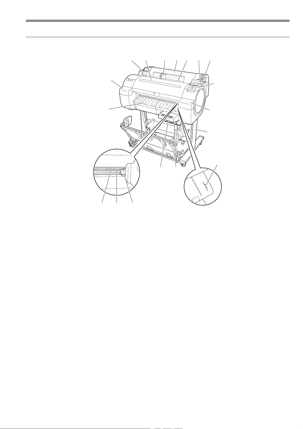
1.5.1 Front
[13]
[6]
[3]
[14]
[9]
[15]
[2] [3] [4]
[1]
[8]
0023-5230
[5]
[6]
[16]
[7]
[11][12]
[1] Roll media cover
Open this cover, and then load roll media.
[2] Media loading slot
Insert media in this slot to load it.
[3] Roll media temporary table
When loading roll media, place the roll holder here and then insert the media in the roll holder slot.
[4] Release lever
When releasing the paper retainer, press this lever backward.
[5] Operation panel
Use this panel to operate the printer or check the printer status.
[6] Ink tank cover
Open this cover to replace the ink tank.
[7] Media alignment line
This orange line is used to align media.
[8] Maintenance cartridge cover
Open this cover to replace the maintenance cartridge.
[9] Maintenance cartridge
This cartridge absorbs the ink used for maintenance. (Replace it when it becomes full of ink.)
[10] Cutter unit
This cutter with a round blade is used to cut roll media automatically.
[11] Cutter rail
The cutter unit moves on this rail to cut media.
[12] Paper eject slot
All printouts are ejected from this slot.
[13] Output guide
A printout is ejected along this guide.
[14] Upper cover
Open this cover to install the printhead or remove the media jammed inside the printer.
[15] Width guide
When loading cassette paper, move this guide according to the paper size.
[16] Stand
Install the printer on this stand. This stand has casters for easy relocation.
[10]
F-1-28
1-13
Chapter 1
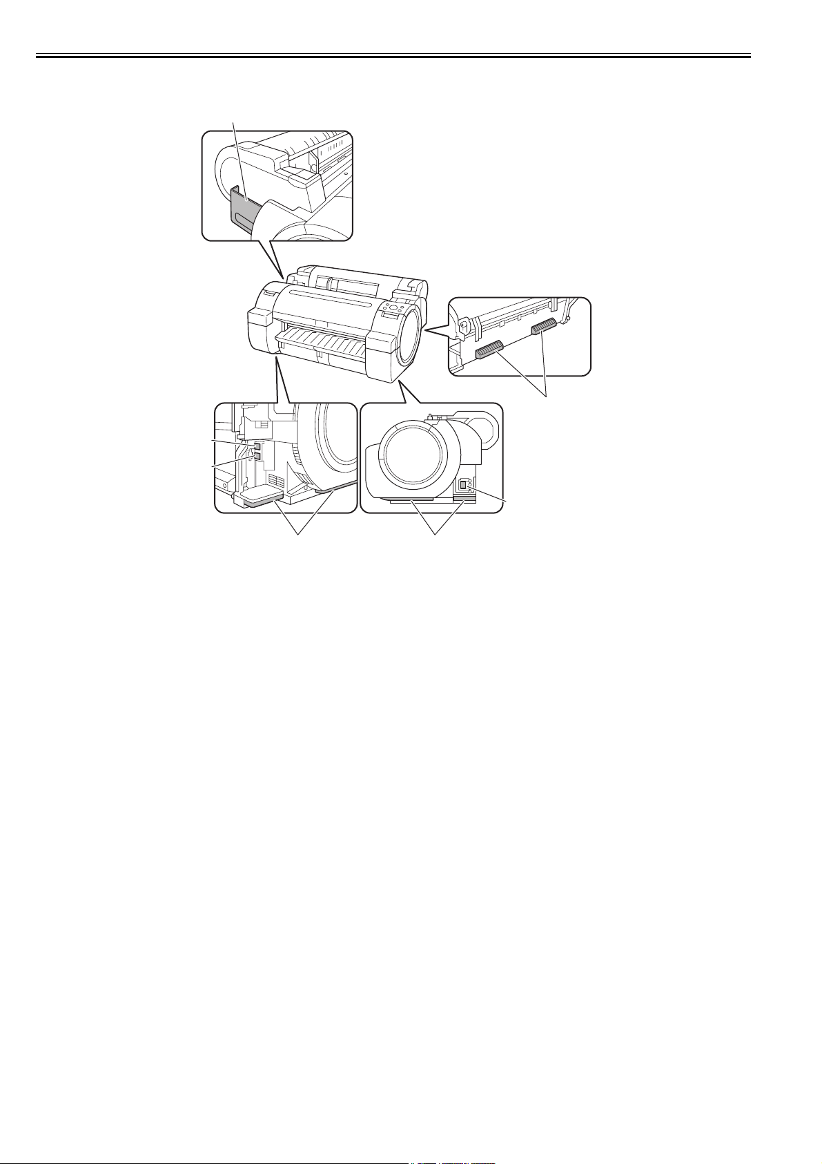
1.5.2 Side
0023-5231
[1]
[4]
[2]
[3]
[5]
[4][4]
F-1-29
[1] Manual pocket
Store the printer manual in this pocket.
[2] Ethernet connector
Connect the Ethernet cable to this connector. The lamp lights when the Ethernet cable is connected properly and the printer is ready to communicate
accordingly.
[3] USB port
Connect the USB cable to this port. This port is compatible with the high-speed USB.
[4] Carrying handles
Three carrying handles provided at the left, right, and back allows three persons to carry the printer.
[5] Power receptacle
Plug the power cord into this receptacle.
1-14
Chapter 1
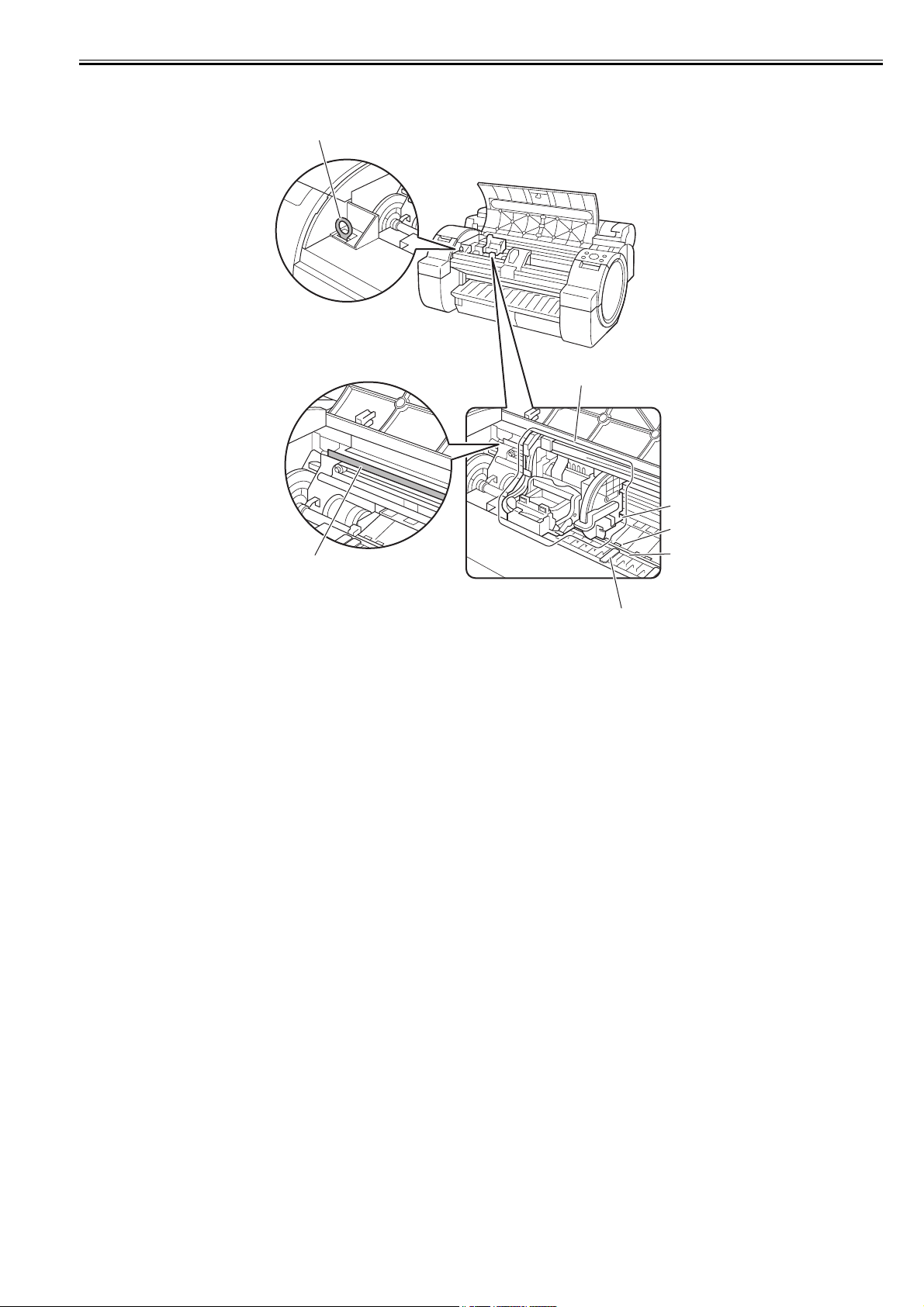
1.5.3 Top Cover (Inside)
0023-5232
[7]
[1]
[2]
[3]
[4]
[6]
[5]
F-1-30
[1] Carriage
The carriage moves the printhead. It is an important component used for printing.
[2] Carriage shaft
The carriage moves on this shaft.
[3] Paper retainer
This is an important component used to feed paper. It retains paper.
[4] Platen
The printhead moves on this component to perform printing. Suction holes are provided on the platen surface to prevent media from floating.
[5] Borderless printing ink catch groove
Ink flowed out of the paper edges enter in this groove during borderless printing.
[6] Linear scale
This is an important component used to detect the carriage position. Never touch it when cleaning the parts or removing jammed media inside the
upper cover.
[7] Cleaner brush
Use this brush to remove paper dust off the platen when cleaning the parts inside the upper cover.
1-15
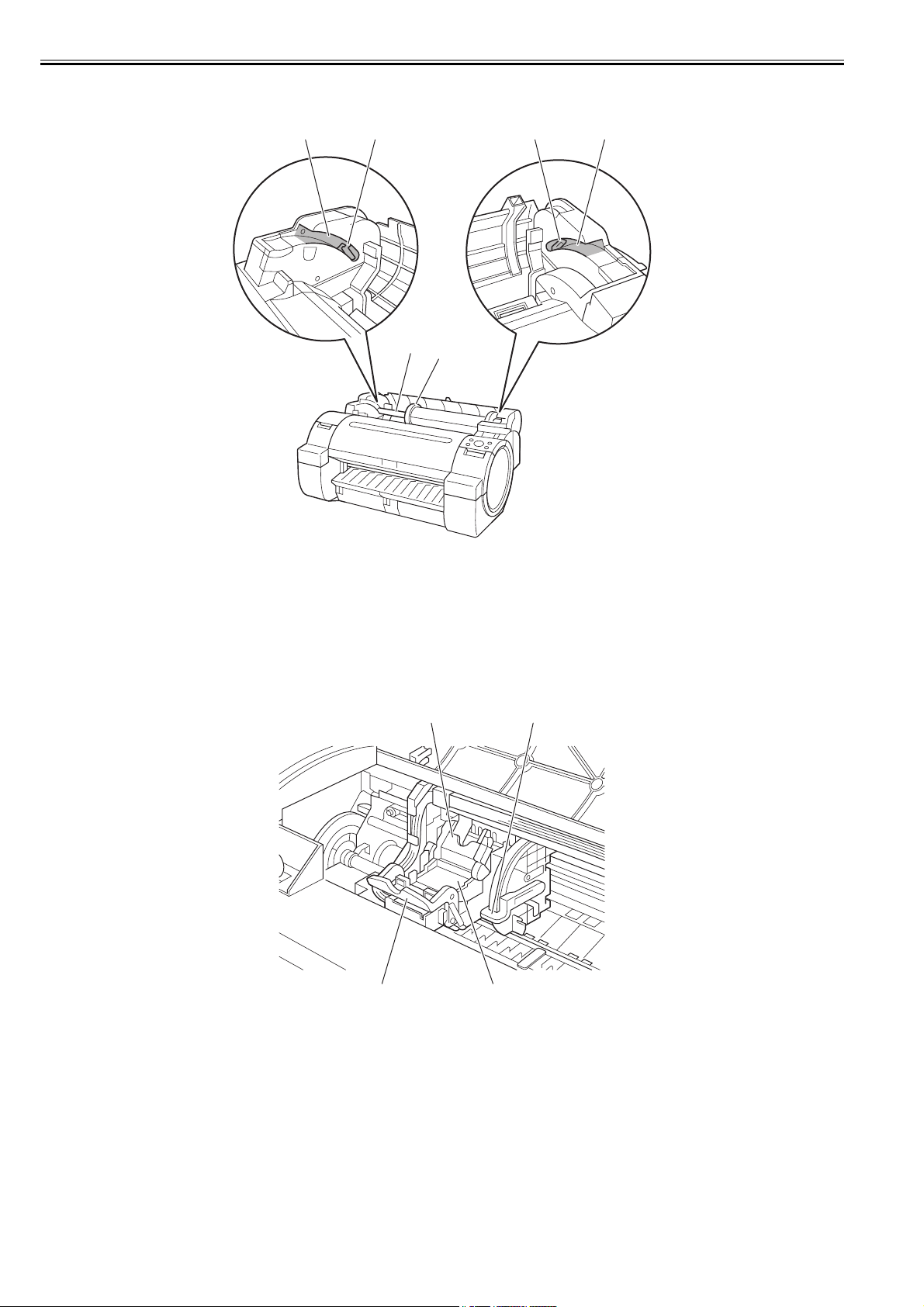
Chapter 1
1.5.4 Roll Unit Cover (Inside)
[3] [4] [3][4]
[1]
[2]
0023-5233
[1] Roll holder
Load roll media in this holder.
[2] Holder stopper
Use this part to secure roll media to the roll holder.
[3] Slide guide
Move the roll holder along this guide.
[4] Roll holder slot
Fit the roll holder in this slot.
1.5.5 Carriage
[1] Slant adjusting lever
This lever is used to fine adjust slant of rules lines.
[2] Printhead
The printhead has nozzles. It is an important component used to perform printing.
[3] Printhead fixer lever
This lever is used to lock the printhead fixer cover.
[4] Printhead fixer cover
This cover is used to secure the printhead.
F-1-31
0023-1267
[1][4]
[3] [2]
F-1-32
1-16
 Loading...