

Canon iPF5000 series Service Manual

Service Manual
iPF5000 series
May 24 2007


Application
This manual has been issued by Canon Inc. for qualified persons to learn technical theory, insta llati on, ma intenance, and repair
of products. This manual covers all localities where the products are sold. For this reason, there may be information in this
manual that does not apply to your locality.
Corrections
This manual may contain technical inaccuracies or typographical errors due to improvements or changes in products. When
changes occur in applicable products or in the contents of this manual, Canon will release technical information as the need
arises. In the event of major changes in the contents of this manual over a long or short period, Canon will issue a new edition
of this manual.
The following paragraph does not apply to any countries where such provisions are inconsistent with local law.
Trademarks
The product names and company names used in this manual are the registered trademarks of the individual companies.
Copyright
This manual is copyrighted with all rights reserved. Under the copyright laws, this manual may not be copied, reproduced or
translated into another language, in whole or in part, without the written consent of Canon Inc.
COPYRIGHT © 2001 CANON INC.
Printed in Japan
Caution
Use of this manual should be strictly supervised to avoid disclosure of confidential information.

Symbols Used
This documentation uses the following symbols to indicate special information:
Symbol Description
Indicates an item of a non-specific nature, possibly classified as Note, Caution, or Warning.
Indicates an item requiring care to avoid electric shocks.
Indicates an item requiring care to avoid combustion (fire).
Indicates an item prohibiting disassembly to avoid electric shocks or problems.
Indicates an item requiring disconnection of the power plug from the electric outlet.
Indicates an item intended to provide notes assisting the understanding of the topic in question.
Memo
Introduction
REF.
Indicates an item of reference assisting the understanding of the topic in question.
Provides a description of a service mode.
Provides a description of the nature of an error indication.

Introduction
The following rules apply throughout this Service Manual:
1. Each chapter contains sections explaining the purpose of specific functions and the relationship between electrical and mechanical systems with reference to the timing of operation.
In the diagrams, represents the path of mechanical drive; where a signal name accompanies the symbol , the arrow indicates the
direction of the electric signal.
The expression "turn on the power" means flipping on the power switch, closing the front door, and closing the delivery unit door, which results in
supplying the machine with power.
2. In the digital circuits, '1'is used to indicate that the voltage level of a given signal is "High", while '0' is used to indicate "Low".(The voltage value, however, differs from circuit to circuit.) In addition, the asterisk (*) as in "DRMD*" indicates that the DRMD signal goes on when '0'.
In practically all cases, the internal mechanisms of a microprocessor cannot be checked in the fi eld. Ther efore, the operations of the microprocessors
used in the machines are not discussed: they are explained in terms of fro m sensors to the input of the DC controller PCB and from the output of the
DC controller PCB to the loads.
The descriptions in this Service Manual are subject to change without notice for product improvement or other purposes, and major changes will be communicated in the form of Service Information bulletins.
All service persons are expected to have a good understanding of the contents of this Service Manual and all relevant Service Information bulletins and be
able to identify and isolate faults in the machine."


Contents
Contents
Chapter 1 PRODUCT DESCRIPTION
1.1 Product Overview .......................................................................................................................................1- 1
1.1.1 Product Overview................................................................................................... ... ..............................................1- 1
1.1.2 Product Overview................................................................................................... ... ..............................................1- 1
1.2 Features .....................................................................................................................................................1- 3
1.2.1 Features ..................................................................................................................................................................1- 3
1.2.2 Features ..................................................................................................................................................................1- 3
1.2.3 Printhead.................................................................................................................................................................1- 3
1.2.4 Ink Tank.......................................................................................................................... ... ......................................1- 3
1.2.5 Cutter ........................................................................................................................................................ ...............1- 5
1.2.6 Auto Roll Feed Unit ............................................................................................................................................. ....1- 5
1.2.7 Roll Feed Unit.......................................................................................................................... .. ..............................1- 5
1.2.8 Stand/Desktop Basket.................................................. ... .................................................. ... ...................................1- 7
1.2.9 IEEE1394 (FireWire) Board.......................................... ... ..................................................... ...................................1- 7
1.2.10 Consumables.........................................................................................................................................................1- 8
1.2.11 Consumables.........................................................................................................................................................1- 9
1.3 Product Specifications..............................................................................................................................1- 10
1.3.1 Product Specifications...........................................................................................................................................1- 10
1.3.2 Product Specifications...........................................................................................................................................1- 11
1.4 Detailed Specifications .............................................................................................................................1- 12
1.4.1 Printing Speed and Direction.................................................................................................................................1- 12
1.4.2 Print Speed and Direction......................................................................................................................................1- 13
1.4.3 Interface Specifications .........................................................................................................................................1- 19
1.5 Names and Functions of Components .....................................................................................................1- 20
1.5.1 Front......................................................................................................................................................................1- 20
1.5.2 Front......................................................................................................................................................................1- 20
1.5.3 Rear.......................................................................................................................................................................1- 22
1.5.4 Top Cover (Inside).................................................................................................................................................1- 22
1.5.5 Manual Loading Area ............................................................................................................................................1- 23
1.5.6 Roll Feed Unit Cover (Inside)................................................................................................................................1- 23
1.5.7 Carriage.................................................................................................................................................................1- 24
1.5.8 Carriage.................................................................................................................................................................1- 24
1.5.9 Inside.....................................................................................................................................................................1- 25
1.5.10 Inside...................................................................................................................................................................1- 26
1.6 Basic Operation........................................................................................................................................1- 27
1.6.1 Operation Panel.....................................................................................................................................................1- 27
1.6.2 Operation Panel.....................................................................................................................................................1- 28
1.6.3 Printer Stats Transition..........................................................................................................................................1- 30
1.6.4 Main Menu.............................................................................................................................................................1- 30
1.6.5 Main Menu.............................................................................................................................................................1- 37
1.7 Safety and Precautions ............................................................................................................................1- 56
1.7.1 Safety Precautions ................................................................................................................................................1- 56
1.7.1.1 Moving Parts..........................................................................................................................................................................1- 56
1.7.1.2 Adhesion of Ink ...................................................................................................................................................................... 1- 56
1.7.1.3 Electric Parts.......................................................................................................................................................................... 1- 57
1.7.1.4 Electric Parts.......................................................................................................................................................................... 1- 58
1.7.2 Other Precautions..................................................................................................................................................1- 58
1.7.2.1 Printhead................................................................................................................................................................................ 1- 58
1.7.2.2 Ink Tank ................................................................................................................................................................................. 1- 59
1.7.2.3 Handling the Printer ............................................................................................................................................................... 1- 60
1.7.3 Precautions When Servicing Printer......................................................................................................................1- 63

Contents
1.7.3.1 Notes on the Data Stored in the Printer................................................................................................................................. 1- 63
1.7.3.2 Confirming the Firmware Version .......................................................................................................................................... 1- 63
1.7.3.3 Precautions against Static Electricity.....................................................................................................................................1- 63
1.7.3.4 Precautions for Disassembly/Reassembly............................................................................................................................. 1- 63
1.7.3.5 Self-diagnostic Feature..........................................................................................................................................................1- 63
1.7.3.6 Disposing of the Lithium Battery ............................................................................................................................................ 1- 63
Chapter 2 TECHNICAL REFERENCE
2.1 Basic Operation Outline .............................................................................................................................2- 1
2.1.1 Printer Diagram........................................................................................................................................................2- 1
2.1.2 Printer Diagram........................................................................................................................................................2- 2
2.1.3 Print Signal Sequence .............................................................................................................................................2- 3
2.1.4 Print Driving .............................................................................................................................................................2- 4
2.2 Firmware ....................................................................................................................................................2- 6
2.2.1 Operation Sequence at Power-on............................................................................................................... .............2- 6
2.2.2 Operation Sequence at Power-off............................................................................................................................2- 6
2.2.3 Print Control.............................................................................................................................................................2- 7
2.2.4 Print Control.............................................................................................................................................................2- 8
2.2.5 Print Position Adjustment Function........................................................................................................................2- 14
2.2.6 Head Management ................................................................................................................................................2- 14
2.2.7 Printhead Overheating Protection Control .............................................................................................................2- 14
2.2.8 Pause between Pages...........................................................................................................................................2- 14
2.2.9 White Raster Skip..................................................................................................................................................2- 14
2.2.10 Sleep Mode..........................................................................................................................................................2- 14
2.3 Printer Mechanical System.. .... ... ... ... .... ... ... ... .... ... ... ... ... .... ... .......................................... ... ... ....................2- 15
2.3.1 Outline....................................................................................................................................................................2- 15
2.3.1.1 Outline.................................................................................................................................................................................... 2- 15
2.3.2 Ink Passage...........................................................................................................................................................2- 16
2.3.2.1 Ink Passage ........................................................................................................................................................................... 2- 16
2.3.2.2 Ink Tank Unit.......................................................................................................................................................................... 2- 18
2.3.2.3 Carriage Unit..........................................................................................................................................................................2- 20
2.3.2.4 Printhead................................................................................................................................................................................ 2- 26
2.3.2.5 Purge Unit..............................................................................................................................................................................2- 27
2.3.2.6 Maintenance Cartridge........................................................................................................................................................... 2- 32
2.3.2.7 Air Flow..................................................................................................................................................................................2- 33
2.3.3 Paper Path.............................................................................................................................................................2- 35
2.3.3.1 Outline.................................................................................................................................................................................... 2- 35
2.3.3.2 Paper Path.............................................................................................................................................................................2- 36
2.3.3.3 Cutter Unit..............................................................................................................................................................................2- 53
2.4 Printer Electrical System ............................... .... ... ... ... ... ....................................... ... .... ... ... .......................2- 54
2.4.1 Outline....................................................................................................................................................................2- 54
2.4.1.1 Overview................................................................................................................................................................................2- 54
2.4.2 Main Controller.......................................................................................................................................................2- 56
2.4.2.1 Main controller components...................................................................................................................................................2- 56
2.4.2.2 Main controller components...................................................................................................................................................2- 57
2.4.3 Carriage Relay PCB.................................. .. ...........................................................................................................2- 59
2.4.3.1 Carriage PCB components .................................................................................................................................................... 2- 59
2.4.4 Motor Driver...........................................................................................................................................................2- 59
2.4.4.1 Cutter driver PCB components .............................................................................................................................................. 2- 59
2.4.4.2 Roll feed unit PCB components.............................................................................................................................................2- 59
2.4.5 Maintenance Cartridge Relay PCB........................................................................................................................2- 60
2.4.5.1 Maintenance cartridge relay PCB components...................................................................................................................... 2- 60
2.4.6 Power Supply............................................................................................................ ... ..........................................2- 60
2.4.6.1 Power supply block diagram..................................................................................................................................................2- 60
2.5 Detection Functions with Sensors..................................... ... ... ... .... ... ... ... .... ... ..........................................2- 60
2.5.1 Sensors for covers.................................................................................................................................................2- 60
2.5.2 Ink passage system...............................................................................................................................................2- 62

Contents
2.5.3 Carriage system ....................................................................................................................................................2- 64
2.5.4 Carriage system ....................................................................................................................................................2- 65
2.5.5 Paper path system.................................................................................................................................................2- 66
2.5.6 Others....................................................................................................................................................................2- 69
Chapter 3 INSTALLATION
3.1 Installation ..................................................................................................................................................3- 1
3.1.1 Making Pre-Checks......................................................................................................................... ... .....................3- 1
3.1.1.1 Making Pre-Checks...................... ............................................................................................................................................ 3- 1
3.1.1.2 Making Pre-Checks...................... ............................................................................................................................................ 3- 1
3.1.2 Unpacking and Installation .............................................................................................................. ... .....................3- 2
3.1.2.1 Unpacking and Installation.......................................................................................................................................................3- 2
3.1.2.2 Unpacking and Installation.....................................................................................................................................................3- 10
3.1.2.3 Installing the Stand ................................................................................................................................................................ 3- 18
3.1.2.4 Installing the Stand ................................................................................................................................................................ 3- 25
3.1.2.5 Installing the Desktop Basket................................................................................................................................................. 3- 34
3.1.2.6 Installing the Desktop Basket................................................................................................................................................. 3- 37
3.1.3 Checking the Images/Operations ..........................................................................................................................3- 41
3.1.3.1 Checking the Images /Operations.......................................................................................................................................... 3- 41
3.2 Transporting the Printer............................................................................................................................3- 42
3.2.1 Transporting the Printer.........................................................................................................................................3- 42
3.2.1.1 Transporting the Printer ......................................................................................................................................................... 3- 42
3.2.2 Reinstalling the Printer ..........................................................................................................................................3- 43
3.2.2.1 Reinstalling the Printer........................................................................................................................................................... 3- 43
Chapter 4 DISASSEMBLY/REASSEMBLY
4.1 Service Parts ..............................................................................................................................................4- 1
4.1.1 Service Parts...................... ... ............................................... ... ................................................................................4- 1
4.2 Disassembly/Reassembly...........................................................................................................................4- 1
4.2.1 Disassembly/Reassembly .......................................................................................................................................4- 1
4.2.2 Disassembly/Reassembly .......................................................................................................................................4- 3
4.3 Points to Note on Disassembly and Reassembly.......................................................................................4- 3
4.3.1 Note on assemblies (or units) prohibited from disassembly....................................................................................4- 3
4.3.2 Moving the carriage manually................................................................................................................................. .4- 3
4.3.3 Units requiring draining of ink..................................................................................................................................4- 3
4.3.4 External Covers................................................................................................................................................... ....4- 5
4.3.5 External Covers.....................................................................................................................................................4- 12
4.3.6 Driving Unit............................................................................................................................................................4- 22
4.3.7 Cutter .....................................................................................................................................................................4- 23
4.3.8 Carriage Unit ............................................................................................................. .. ..........................................4- 25
4.3.9 Carriage Unit ............................................................................................................. .. ..........................................4- 29
4.3.10 Feeder Unit........................................................... ... .................................................. ... .......................................4- 37
4.3.11 Roll Feed Unit......................................................................................................................................................4- 42
4.3.12 Purge Unit............................................................................................................................................................4- 45
4.3.13 Purge Unit............................................................................................................................................................4- 46
4.3.14 Waste Ink Collection Unit.....................................................................................................................................4- 49
4.3.15 Ink Tank Unit........................................................................................................................................................4- 52
4.3.16 Head Management Sensor..................................................................................................................................4- 55
4.3.17 Multi Sensor.........................................................................................................................................................4- 55
4.3.18 PCBs....................................................................................................................................................................4- 57
4.3.19 Opening the Cap/Moving the Wiper Unit.............................................................................................................4- 60
4.3.20 Opening the Cap/Moving the Wiper Unit.............................................................................................................4- 60
4.3.21 Opening/Closing the Ink Supply Valve ................................................................. ...............................................4- 62
4.3.22 Draining the Ink....................................................................................................................................................4- 63
4.4 Applying the Grease.................................................................................................................................4- 64

Contents
4.4.1 Applying the Grease ..............................................................................................................................................4- 64
4.5 Adjustment and Setup Items ....................................................................................................................4- 71
4.5.1 Adjustment Item List ........................................................................................... ... ................................................4- 71
4.5.2 Procedure after Replacing the Feed Roller HP Sensor or Feed Roller Encoder...................................................4- 71
4.5.3 Procedure after Replacing the Carriage Unit or Multi Sensor................................................................................4- 71
4.5.4 Procedure after Replacing the Head Management Sensor ...................................................................................4- 74
Chapter 5 MAINTENANCE
5.1 Periodic Replacement Parts.................... ... ................................................................................................5- 1
5.1.1 Periodic Replacement Parts ....................................................................................................................................5- 1
5.2 Consumable Parts......................................................................................................................................5- 1
5.2.1 Consumable Parts ...................................................................................................................................................5- 1
5.2.2 Consumable Parts ...................................................................................................................................................5- 1
5.3 Periodic Maintenance.............. ... ... ... .... ... ...................................................................................................5- 2
5.3.1 Periodic Maintenance .................................................................................................................................... ..........5- 2
5.3.2 Periodic Maintenance .................................................................................................................................... ..........5- 2
Chapter 6 TROUBLESHOOTING
6.1 Troubleshooting..........................................................................................................................................6- 1
6.1.1 Outline.................................................................................................................................................................... ..6- 1
6.1.1.1 Outline of Troubleshooting.......................................................................................................................................................6- 1
6.1.2 Troubleshooting When Warnings Occur..................................................................................................................6- 1
6.1.2.1 Ink Lvl: Chk XX (1000,1001,1002,1003,1004,1005,1006,1008,1009,100A,100B,100C)......................................................... 6- 1
6.1.2.2 MTCart Full Soon (1100) ......................................................................................................................................................... 6- 1
6.1.2.3 Mist Full Soon (1101)...............................................................................................................................................................6- 1
6.1.2.4 GARO W12xx: xx stands for digits (1221,1222,1223,1225,1231,1232,1233,1234,1235) .......................................................6- 1
6.1.2.5 Feed Limit... (100F).................................................................................................................................................................. 6- 2
6.1.2.6 Check printed document.(1010)............................................................................................................................................... 6- 2
6.1.3 Troubleshooting When Errors Occur .......................................................................................................................6- 2
6.1.3.1 01800500-1012/01800500-1013 Defective printhead nozzle .................................................................................................. 6- 2
6.1.3.2 03010000-200C/03010000-2017/03010000-2018/03016000-2010 Multi sensor error............................................................ 6- 2
6.1.3.3 03010000-200D Cut sheet end cannot be detected ................................................................................................................6- 2
6.1.3.4 03010000-2820/03010000-2821/03010000-2822/03010000-2823/03130031-2F32/03010000-2F33 Adjustment error.........6- 3
6.1.3.5 03010000-2E1F/03060000-2E14/03061000-2E15/03060000-2E16/03060200-2E03/03060200-2E0B/03060A00-2E00/
03060A00-2E01/03860002-2E0A Path mismatch error................................................................................................................. 6- 3
6.1.3.6 03010000-2E25/03010000-2E27 Paper feed/delivery jam error ............................................................................................. 6- 3
6.1.3.7 03030000-2E21 IEEE1394 error.............................................................................................................................................. 6- 4
6.1.3.8 03060A00-2E0E Roll media unit uninstallation........................................................................................................................6- 4
6.1.3.9 03060A00-2E1B Roll media end error..................................................................................................................................... 6- 4
6.1.3.10 03130031-291B Lift home position error................................................................................................................................ 6- 4
6.1.3.11 03130031-291D Supr cam sensor error................................................................................................................................. 6- 5
6.1.3.12 03130031-2E23 Cutter unit breakdown ................................................................................................................................. 6- 5
6.1.3.13 03130031-2F13 A/D Converter external trigger output stopped ............................................................................................ 6- 5
6.1.3.14 03130031-2F14 ASIC Register cannot be written................................................................................................................. 6- 5
6.1.3.15 03130031-2F16 Mist fan error................................................................................................................................................ 6- 5
6.1.3.16 03130031-2F17 Suction fan error..........................................................................................................................................6- 6
6.1.3.17 03130031-2F20/03130031-2F28/03130031-2F22/03130031-2F23 Defective sensor in purge unit......................................6- 6
6.1.3.18 03130031-2F24 Cutter drive time-out error............................................................................................................................ 6- 6
6.1.3.19 03130031-2F25 Carriage home position error.......................................................................................................................6- 6
6.1.3.20 03130031-2F26/03130031-2F27 Carriage motor error.......................................................................................................... 6- 7
6.1.3.21 03130031-2F2A Feed roller home position error................................................................................................................... 6- 7
6.1.3.22 03130031-2F2D The cassette cannot work...........................................................................................................................6- 7
6.1.3.23 03130031-2F2E Roll drive time-out error............................................................................................................................... 6- 7
6.1.3.24 03130031-2F3A Valve open/close error ................................................................................................................................ 6- 8
6.1.3.25 03180003-2E22 MIT error...................................................................................................................................................... 6- 8
6.1.3.26 03180101-2E17 Cassette uninstallation ................................................................................................................................ 6- 8
6.1.3.27 03800200-2802/03800400-2803/03800300-2801/03800201-280A/03800401-280B/03800301-2809/03800200-2804/

Contents
03800202-2807 Printhead error..................................................................................................................................................... 6- 8
6.1.3.28 03800500-2F2F/03800500-2F30 Head management sensor error....................................................................................... 6- 9
6.1.3.29 03810101-2501/03810102-2502/03810103-2503/03810104-2500/03810105-2508/03810106-2506/03810107-250A/
03810108-250C/03810109-250B/03810112-2504/03810113-2505/03810115-2509 No ink error.................................................6- 9
6.1.3.30 03810201-2581/03810204-2580/03810202-2582/03810203-2583/03810212-2584/03810213-2585/03810206-2586/
03810205-2588/03810215-2589/03810207-258A/03810209-258B/03810208-258C Tank level error 1.......................................6- 9
6.1.3.31 03810201-2591/03810204-2590/03810202-2592/03810203-2593/03810212-2594/03810213-2595/03810206-2596/
03810205-2598/03810215-2599/03810207-259A/03810209-259B/03810208-259C Tank level error 2.......................................6- 9
6.1.3.32 03830101-2521/03830104-2520/03830102-2522/03830103-2523/03830112-2524/03830113-2525/03830106-2526/
03830105-2528/03830115-2529/03830107-252A/03830109-252B/03830108-252C Ink tank is not installed.(This error occurs when
the ink tank is replaced.) .............................................................................................................................................................. 6- 10
6.1.3.33 03830201-2541/03800204-2540/03830202-2542/03830203-2543/03830212-2544/03830213-2545/03830206-2546/
03830205-2548/03830215-2549/03830207-254A/03830209-254B/03830208-254C Invalid ink tank ID..................................... 6- 10
6.1.3.34 03830301-2561/03830304-2560/03830302-2562/03830303-2563/03830312-2564/03830313-2565/03830306-2566/
03830305-2568/03830305-2568/03830315-2569/03830307-256A/03830309-256B/03830308-256C Ink tank EEPROM error.6- 10
6.1.3.35 03841001-2819/03841201-2816/03841201-2817/03841101-2818/01841001-281B Maintenance cartridge error.............. 6- 10
6.1.3.36 03861001-2405/03861001-2406 Borderless printing error .................................................................................................. 6- 11
6.1.3.37 03862000-2E09 Insufficient roll media error ........................................................................................................................ 6- 11
6.1.3.38 03870001-2015 Cut error.....................................................................................................................................................6- 11
6.1.3.39 E194-4034 Sensor calibration error .................................................................................................................................... 6- 11
6.1.4 Troubleshooting When Service Call Errors Occur.................................................................................................6- 12
6.1.4.1 Outline.................................................................................................................................................................................... 6- 12
6.1.4.2 E141-4046 Recovery system rotation count reached 50,000................................................................................................ 6- 12
6.1.4.3 E144-4047 Supply system's count error ................................................................................................................................ 6- 12
6.1.4.4 E146-4001 Borderless/idle ejection/mist collection count full ................................................................................................ 6- 12
6.1.4.5 E194-404A Non-discharge detection count error................................................................................................................... 6- 12
6.1.4.6 E161-403E/E196-403F Abnormally high head temperature..................................................................................................6- 12
6.1.4.7 E196-4040/E196-4041/E196-4042/E196-4045/E196-4049 main controller PCB error ......................................................... 6- 13
6.1.4.8 E198-401C/E198-401D/E198-401E RTC error...................................................................................................................... 6- 13
6.2 Location of Connectors and Pin Arrangement..........................................................................................6- 13
6.2.1 Main controller PCB...............................................................................................................................................6- 13
6.2.2 Main controller PCB...............................................................................................................................................6- 24
6.2.3 Carriage PCB ............................................................ ... .................................................. .......................................6- 36
6.2.4 Carriage PCB ............................................................ ... .................................................. .......................................6- 43
6.2.5 Cutter driver PCB ..................................................................................................................................................6- 52
6.2.6 Power supply............................................................. .................................................. ... .......................................6- 52
6.2.7 Power supply............................................................. .................................................. ... .......................................6- 54
6.2.8 Roll feed unit PCB.................................................................................................................................................6- 54
6.3 Version Up................................................................................................................................................6- 56
6.3.1 Firmware Update Tool...........................................................................................................................................6- 56
6.4 Service Tools............................................................................................................................................6- 57
6.4.1 Tool List.......................................................... .................................................. .....................................................6- 57
Chapter 7 SERVICE MODE
7.1 Service Mode..............................................................................................................................................7- 1
7.1.1 Service Mode Operation.......................................................... ... .............................................................................7- 1
7.1.2 Map of the Service Mode.........................................................................................................................................7- 2
7.1.3 Details of Service Mode..................................... .................................................. ..................................... ...............7- 7
7.1.4 Sample Printout.....................................................................................................................................................7- 15
7.2 Special Mode............................................................................................................................................7- 19
7.2.1 Special Modes for Servicing..................... ... ... .......................................................................................................7- 19
Chapter 8 ERROR CODE
8.1 Outline ........................................................................................................................................................8- 1
8.1.1 Outline.....................................................................................................................................................................8- 1
8.2 Error Table..................................................................................................................................................8- 1
8.2.1 Error Code List ................................................................................................................................................. .......8- 1

Contents
8.3 Sevice Call Table .......................................................................................................................................8- 4
8.3.1 Service Call Errors....................................................... ............................................................................................8- 4

Chapter 1 PRODUCT DESCRIPTION


Contents
Contents
1.1 Product Overview .......................................................................................................................................................... 1-1
1.1.1 Product Overview ........................................................................................................................................................................ 1-1
1.1.2 Product Overview ........................................................................................................................................................................ 1-1
1.2 Features..........................................................................................................................................................................1-3
1.2.1 Features........................................................................................................................................................................................ 1-3
1.2.2 Features........................................................................................................................................................................................ 1-3
1.2.3 Printhead ...................................................................................................................................................................................... 1-3
1.2.4 Ink Tank....................................................................................................................................................................................... 1-3
1.2.5 Cutter............................................................................................................................................................................................ 1-5
1.2.6 Auto Roll Feed Unit..................................................................................................................................................................... 1-5
1.2.7 Roll Feed Unit.............................................................................................................................................................................. 1-5
1.2.8 Stand/Desktop Basket .................................................................................................................................................................. 1-7
1.2.9 IEEE1394 (FireWire) Board............................................................... ......................................................................................... 1-7
1.2.10 Consumables.............................................................................................................................................................................. 1-8
1.2.11 Consumables.............................................................................................................................................................................. 1-9
1.3 Product Specifications..................................................................................................................................................1-10
1.3.1 Product Specifications ............................................................................................................................................................... 1-10
1.3.2 Product Specifications ............................................................................................................................................................... 1-11
1.4 Detailed Specifications ................................................................................................................................................1-12
1.4.1 Printing Speed and Direction ..................................................................................................................................................... 1-12
1.4.2 Print Speed and Direction .......................................................................................................................................................... 1-13
1.4.3 Interface Specifications.............................................................................................................................................................. 1-19
1.5 Names and Functions of Components ......................................................................................................................... 1-20
1.5.1 Front........................................................................................................................................................................................... 1-20
1.5.2 Front........................................................................................................................................................................................... 1-20
1.5.3 Rear............................................................................................................................................................................................ 1-22
1.5.4 Top Cover (Inside)..................................................................................................................................................................... 1-22
1.5.5 Manual Loading Area ................................................................................................................................................................ 1-23
1.5.6 Roll Feed Unit Cover (Inside).................................................................. .................................................................................. 1-23
1.5.7 Carriage...................................................................................................................................................................................... 1-24
1.5.8 Carriage...................................................................................................................................................................................... 1-24
1.5.9 Inside.......................................................................................................................................................................................... 1-25
1.5.10 Inside........................................................................................................................................................................................ 1-26
1.6 Basic Operation............................................................................................................................................................ 1-27
1.6.1 Operation Panel.......................................................................................................................................................................... 1-27
1.6.2 Operation Panel.......................................................................................................................................................................... 1-28
1.6.3 Printer Stats Transition .............................................................................................................................................................. 1-30
1.6.4 Main Menu................................................................................................................................................................................. 1-30
1.6.5 Main Menu................................................................................................................................................................................. 1-37
1.7 Safety and Precautions.................................................................................................................................................1-56
1.7.1 Safety Precautions...................................................................................................................................................................... 1-56
1.7.1.1 Moving Parts .................................................................................................................................................................................................1-56
1.7.1.2 Adhesion of Ink.............................................................................................................................................................................................1-56
1.7.1.3 Electric Parts .................................................................................................................................................................................................1-57
1.7.1.4 Electric Parts .................................................................................................................................................................................................1-58
1.7.2 Other Precautions....................................................................................................................................................................... 1-58
1.7.2.1 Printhead .......................................................................................................................................................................................................1-58
1.7.2.2 Ink Tank ........................................................................................................................................................................................................1-59
1.7.2.3 Handling the Printer ......................................................................................................................................................................................1-60
1.7.3 Precautions When Servicing Printer .................. ....................................................... ................................................................. 1-63

Contents
1.7.3.1 Notes on the Data Stored in the Printer ........................................................................................................................................................1-63
1.7.3.2 Confirming the Firmware Version.......................... ... ... ...................................... .... ... ...................................................................................1-63
1.7.3.3 Precautions against Static Electricity............................................................................................................................................................1-63
1.7.3.4 Precautions for Disassembly/Reassembly ....................................................................................................................................................1-63
1.7.3.5 Self-diagnostic Feature .................................................................................................................................................................................1-63
1.7.3.6 Disposing of the Lithium Battery ........................................ ... ...................................... ................................................................................1-63

1.1 Product Overview
Chapter 1
1.1.1 Product Overview
iPF5000
0013-2854
This printer is capable of printing on A4- to A2-size cut sheets and its maximum print width is 17 inches. This printer is a desktop large-format printer twelve-colors
(pigment-based colors) printer that can be used to print office documents as well as handy POP and posters. An auto roll feed unit is optionally available for printing
on roll media.
[1]
[7]
[17]
[2]
[5]
[4]
[18]
[6]
[19]
[3]
[8]
[9]
[13]
[14]
[12]
[10]
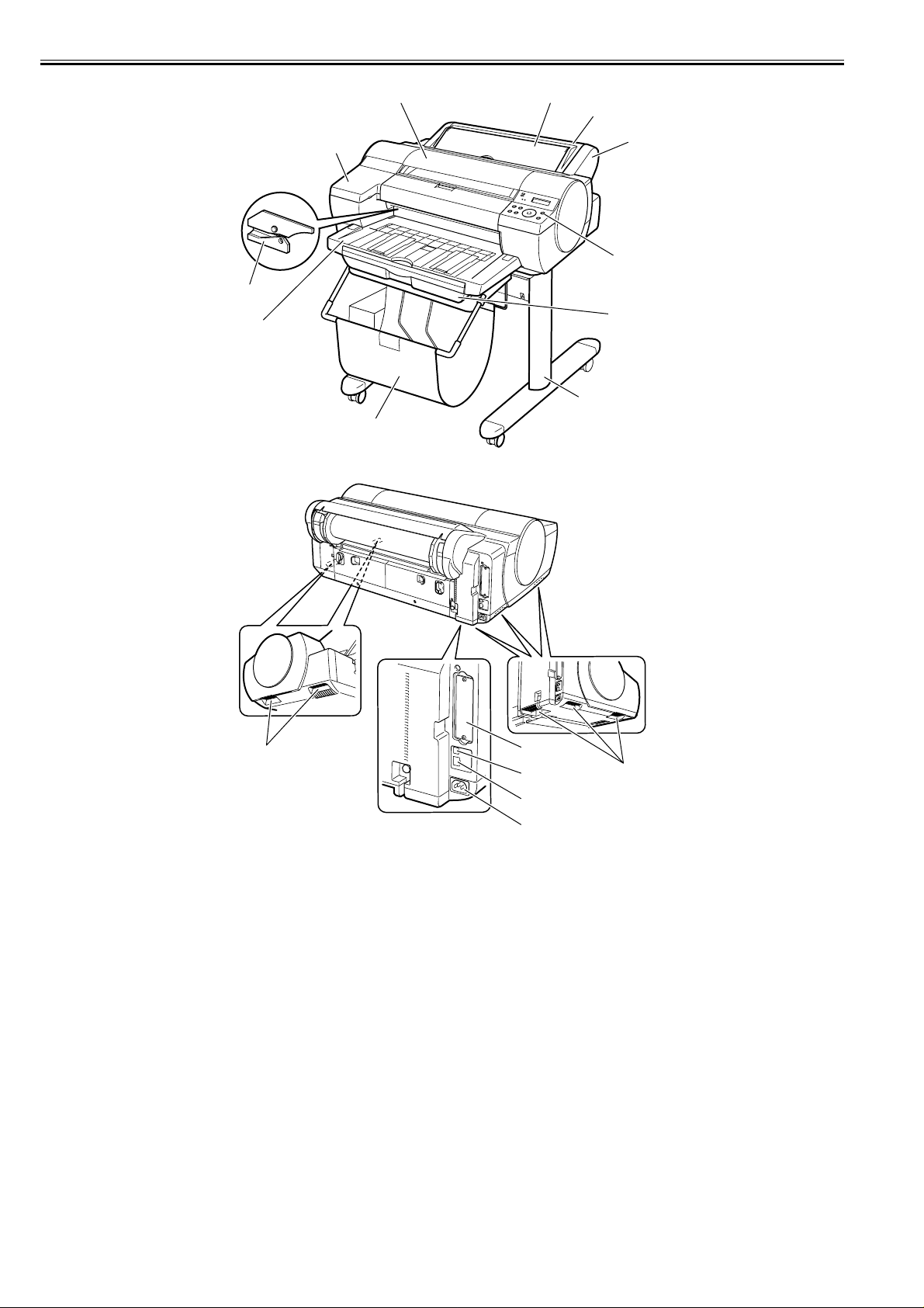
[1] Top Cover [11] Ethernet Connector
[2] Ink Tank Cover [12] USB Port
[3] Cassette [13] Expansion Board Slot
[4] Operation Panel [14] Printhead
[5] Paper Tray Unit [15] Ink Tank
[6] Output Tray [16] Cleaning Brush
[7] Auto Roll Feed Unit (option) [17] Maintenance Cartridge
[8] Roll Holder Set (included with auto roll feed unit) [18] Stand (option)
Back Cover
[9]
[10] Power Supply Connector
[11]
F-1-1
T-1-1
Output Stacker (included with stand or desktop basket)
[19]
[15]
[16]
1.1.2 Product Overview
iPF5100
This printer is capable of printing on A4- to A2-size cut sheets and its maximum print width is 17 inches. This printer is a desktop large-format printer twelve-colors
(pigment-based colors) printer that can be used to print office documents as well as handy POP and posters. An auto roll feed unit is equipped for printing on roll
media.
0016-8119
1-1
Chapter 1
[3]
[4]
[2]
[1] [11]
[10]
[9]
[8]
[7]
[6]
[5]
F-1-2
[16]
[15]
[14]
[13]
[12]
F-1-3
T-1-2
[1] Top Cover [9] Roll Feed Unit
[2] Ink Tank Cover [10] Roll Feed Unit Cover
[3] Cutter [11] Manual Feed Cover
[4] Output Tray [12] Power Connector
[5] Basket [13] Ethernet Connector
[6] Stand [14] USB Port
[7] Cassette [15] Expansion Board Slot
[8] Operation Panel [16] Carrying Handle
[16]
1-2
1.2 Features
Chapter 1
1.2.1 Features
iPF5000
- One-inch wide printhead having 2,560 nozzles per color, which are twice as many as the those of the existing models. High-density printhead technology "FINE"
that can satisfy both of beautiful and fast printing requirements of a high order is employed for accurate ejection of ultrasmall 4-pl drops of ink to the target positions.
Prints with 2400 x 1200 dpi resolution can be made at a high speed.
- Imaging processor "L-COA" incorporated for high-speed image data processing. High-speed processing of 12-color, 2-bit large-size images and printer control
for high-accuracy operation of high-density double head can be performed with a single chip.
- Support for roll media (option), cassette paper pick -up, manual feed from front, and manual feed from top (4-way paper supply). A maximum o f 1 .5 mm th ick of
paper can be manually fed from the front.
- Borderless printing on and auto cutting of roll media (option)
- Standard support for 10Base-T/100Base-TX. Standard support for USB 2.0 High-Speed. Optional support for IEEE1394.
- Data scanned using CanoScan can be easily printed on large-size paper just like a dedicated copier. Just pressing the Start button allows you to blow up an original
of up to A3 size in collaboration with Canon Image RUNNER.
0014-3594
- Support for remote notification utility which is used to send an E-mail when an alarm or error occurs.
1.2.2 Features
iPF5100
0016-8106
- A new 12-color pigmented ink formulation featuring additional three types of special-color inks (red, green, blue) and two types of gray ink varying in grayscale,
"Lucia" prints on a variety of grades of paper, from glossy paper to art, mat and sign, with a high degree of coloring.
- Two types of black ink, vividly glossy "black ink" and "mat black ink" full of a sense of high quality, are loaded concurrently and are selected automatically to
suit paper types. There is no need to manually change inks.
- BK (black)/GY (gray)/PGY (photo gray ) ink are mainly used to offer a drastically enhanced power of halftoning, achieving an equivalent of the high picture quality
of monochrome silver-salt films.
- One-inch wide printhead having 2,560 nozzles per color, which are twice as many as the those of the existing models. High-density printhead technology "FINE"
that can satisfy both of beautiful and fast printing requirements of a high order is employed for accurate ejection of ultrasmall 4-pl drops of ink to the target positions.
Prints with 2400 x 1200 dpi resolution can be made at a high speed.
- Imaging processor "L-COA" incorporated for high-speed image data processing. High-speed processing of 12-color, 2-bit large-size images and printer control
for high-accuracy operation of high-density double head can be performed with a single chip.
- Support for roll media, cassette paper pick-up, manual feed from front, and manual feed from top (4-way paper supply). A maximum of 1.5 mm thick of paper
(POP Board) can be manually fed from the front.
- Borderless printing on and auto cutting of roll media.
- Standard support for 10Base-T/100Base-TX. Standard support for USB 2.0 High-Speed. Optional support for IEEE1394.
- Data scanned using CanoScan can be easily printed on large-size paper just like a dedicated copier. Just pressing the Start button allows you to blow up an original
of up to A3 size in collaboration with Canon Image RUNNER.
- Support for remote notification utility which is used to send an E-mail when an alarm or error occurs.
Functional enhancements new to this model include:
- Higher image quality
Use of abrasion-resistant inks (MBK, BK, PGY, GY) offers enhanced image durability.
The color calibration feature adds to the faithfulness of color reproduction.
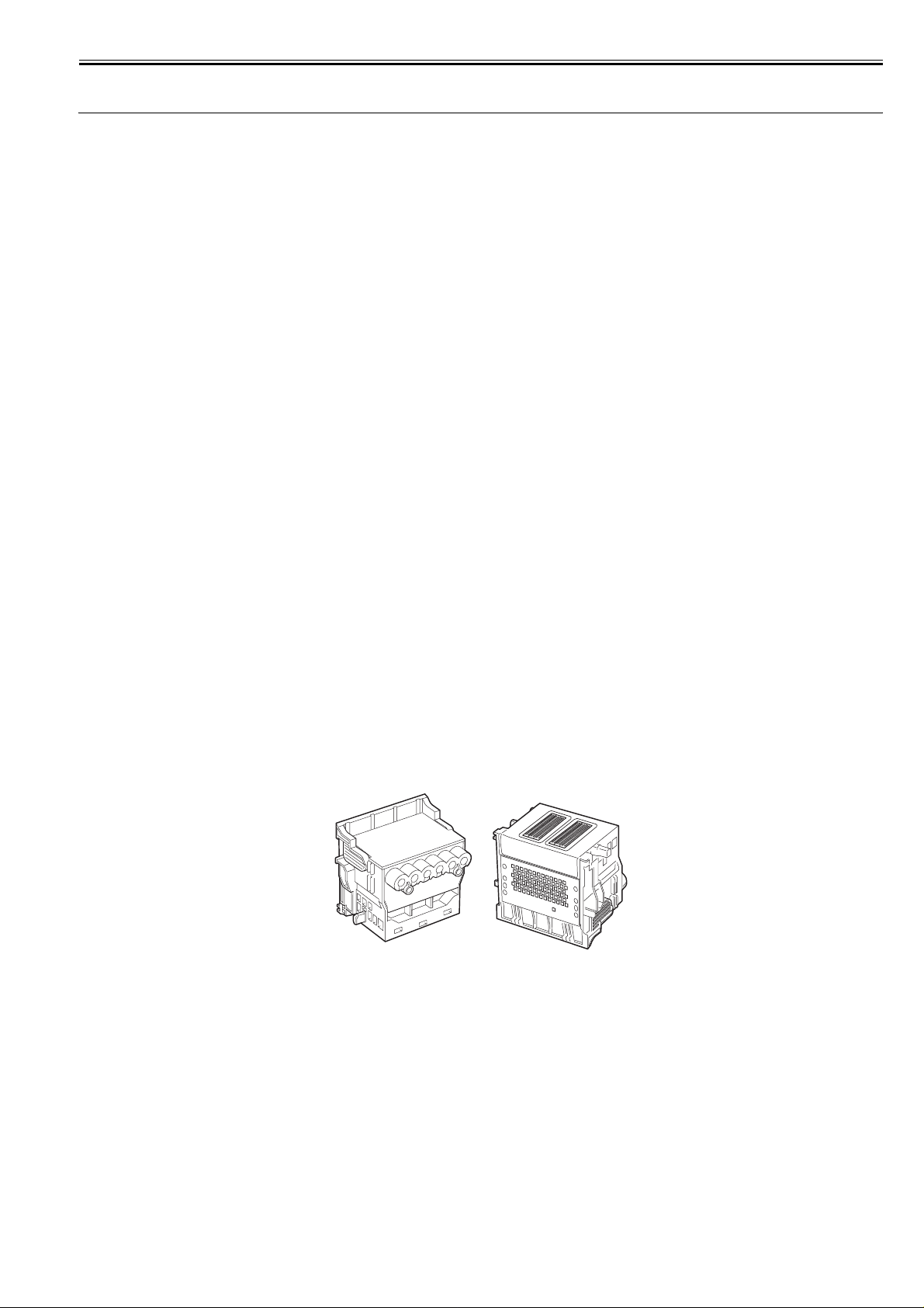
1.2.3 Printhead
iPF5000 / iPF5100
Printhead set on the carriage is a 6-color integral disposable type.
On the printhead, two rows of 1,280 nozzles (total 2,560 nozzles) are arranged in a staggered pattern. .
If print quality does not improve despite carrying out the specified cleaning, the printhead must be replaced with a new one. Generally, it is recommended that the
0012-6187
printhead be replaced about 12 months after you have opened the package.
F-1-4
1.2.4 Ink Tank
iPF5000 / iPF5100
The ink tank is disposable.
There are twelve pigment-based ink colors (matte black,black,photo cyan,cyan,photo magenta,magenta,yellow,red,blue,green,gray,and photo gray).
This printer features a mechanism by which only the correct color ink tank will fit in the given slot.
When the message No Ink is displayed, replace the ink tank with a new one. Also, each ink tank should generally be replaced six months after you have opened the
package.
0013-0608
1-3

Chapter 1
F-1-5
1-4
Chapter 1
1.2.5 Cutter
iPF5000 / iPF5100
0013-3524
A round-blade cuter comes with the cutter unit.
F-1-6
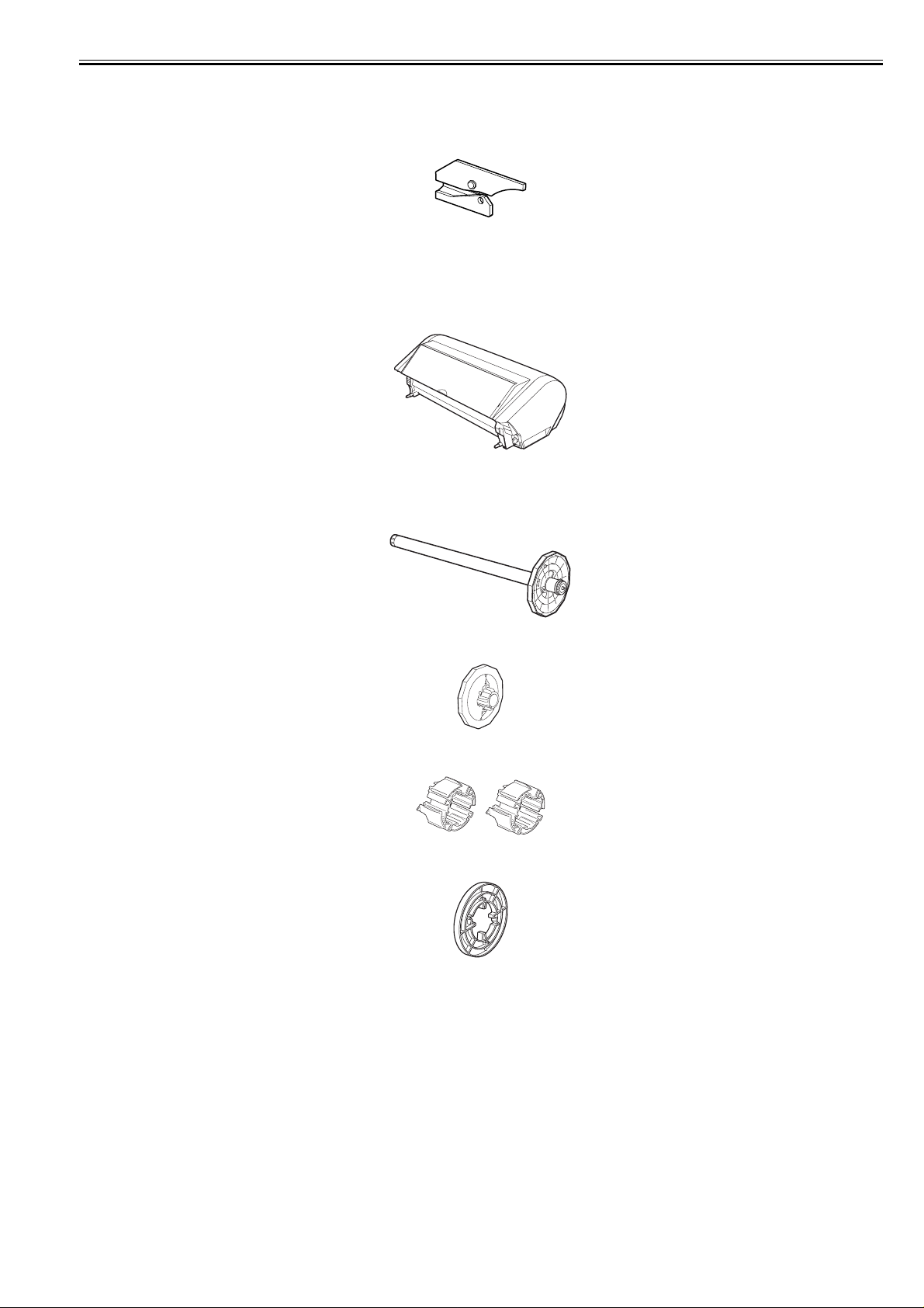
1.2.6 Auto Roll Feed Unit
iPF5000
Auto Roll Feed Unit (option)
The auto roll feed unit is optionally available to use roll media with this printer.
F-1-7
Roll holder set (option)
This set consists of roll holder, holder stopper, 3-inch paper tube attachment (two), and borderless printing spacer (commonly used for 2-inch paper tube and 3-inch
paper tube).
[Roll holder]
0013-2356
[Holder stopper]
[3-inch paper tube attachment](2 pcs.)
[Borderless printing spacer]
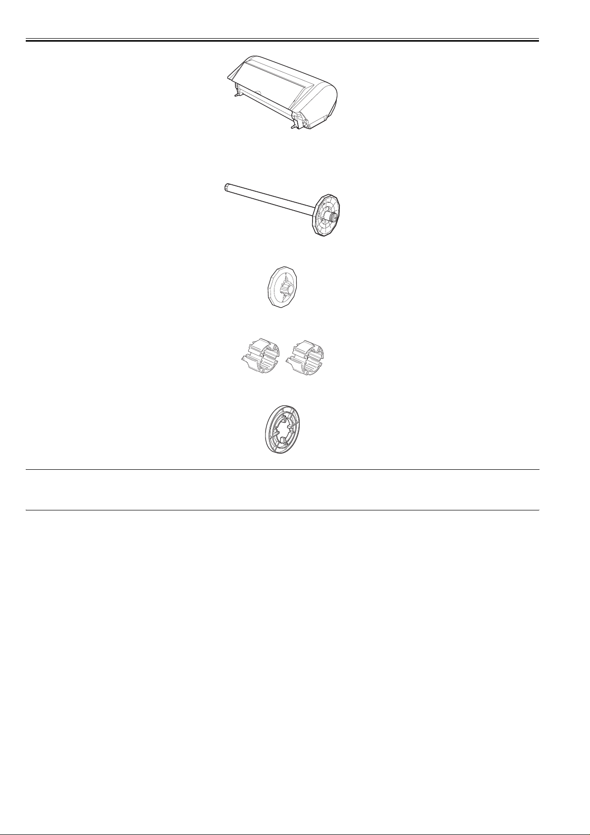
1.2.7 Roll Feed Unit
iPF5100
Roll Feed Unit
The roll feed unit is optionally available to use roll media with this printer.
F-1-8
F-1-9
F-1-10
F-1-11
0013-2512
1-5
Chapter 1
F-1-12
Roll holder set
This set consists of roll holder, holder stopper, 3-inch paper tube attachment (two), and borderless printing spacer (commonly used for 2-inch paper tube and 3-inch
paper tube).
[Roll holder]
F-1-13
[Holder stopper]
F-1-14
[3-inch paper tube attachment](2 pcs.)
F-1-15
[Borderless printing spacer]
F-1-16
MEMO:
A borderless printing spacer is used to perform borderless printing on A2-size (420 mm) roll media. This printer is furnished with a number of borderless printing
ink receiving channels on the platen to address multi-sized borderless printing needs. Borderless printing on A2-size roll media is made possible by using a spacer,
without needing to produce a new borderless printing ink receiving channel.
1-6
Chapter 1
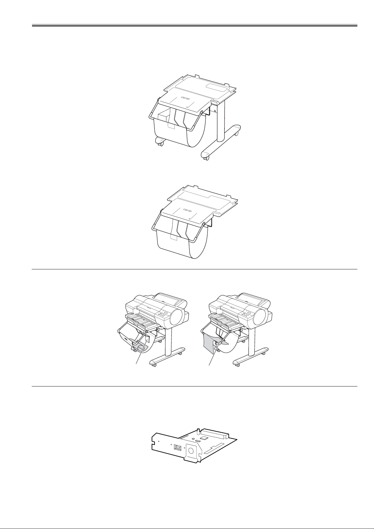
1.2.8 Stand/Desktop Basket
iPF5000 / iPF5100
0016-3882
Stand (option)
It is a stand that puts the printer. Equipped with casters so that the printer can be easily moved. The output stacker included with stand can use by the two ways of
the regular position or extended position.
F-1-17
Desktop Basket (option)
It is a basket unit that uses the output stacker in the printer on the desktop. The output stacker can use by th e two ways o f t he reg ular pos ition or extended po sition.
F-1-18
MEMO:
Use the output stacker in the regular position [A]. However, for the specified media, it can also be used in the extended position [B]. The media can be removed
more easily when the output stacker is in the extended position.
[A]
1.2.9 IEEE1394 (FireWire) Board
iPF5000 / iPF5100
[B]
F-1-19
0016-8123
IEEE1394 (FireWire) expansion board (option)
An interface board that provides an additional IEEE1394 (FireWire) port.
F-1-20
1-7
Chapter 1
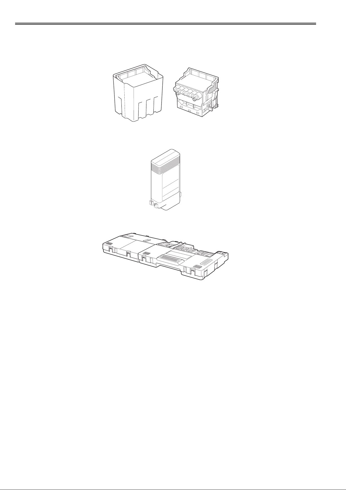
1.2.10 Consumables
iPF5000
0013-0609
Printhead
The consumable print head is the same as that supplied with the printer.
F-1-21
Ink Tanks
The consumable ink tanks are available in twelve colors (matte black, black, photo cyan, cyan, photo magenta, magenta, yellow, red, blue, green, photo gray, and
gray). They are the same as those supplied with the printer. Each ink tank must be replaced with a new one six month after you have opened the package.
F-1-22
Maintenance cartridge
The consumable maintenance cartridge is the same as that supplied with the printer.
F-1-23
1-8
Chapter 1
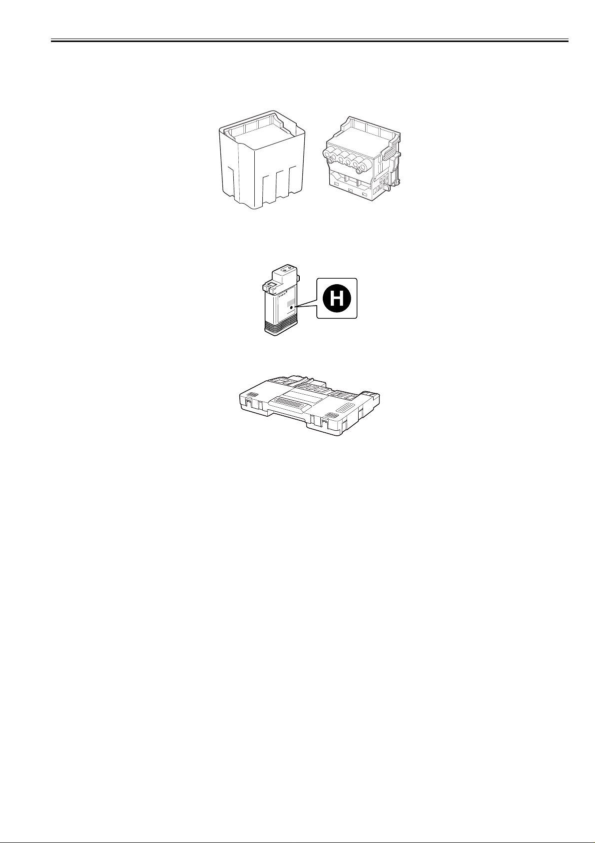
1.2.11 Consumables
iPF5100
0016-8110
Printhead
The consumable print head is the same as that supplied with the printer.
F-1-24
Ink Tanks
The consumable ink tanks are available in twelve colors (matte black, black, photo cyan, cyan, photo magenta, magenta, yellow, red, blue, green, photo gray, and
gray). They are the same as those supplied with the printer. Each ink tank must be replaced with a new one six month after you have opened the package.
The ink tank that can be used with this printer is labeled "H".
F-1-25
Maintenance cartridge
The consumable maintenance cartridge is the same as that supplied with the printer.
F-1-26
1-9

Chapter 1
1.3 Product Specifications
1.3.1 Product Specifications
iPF5000
Type Bubble jet large-sized paper printer
Feeding system Automatic feeding of one roll media (option)/Cassette paper feedin g/
Feeding capacity - Roll media (option)
Delivery method Delivers the media with its printed side up in the forward direction.
Sheet delivery capability - Roll media (option)
Cutter Automatically cuts paper laterally. Cartridge-type (with round blade)
Type of media Plain paper, plain paper (high quality), plain paper (vivid color), coated
Supported thickness Roll media: 0.07 to 0.8 mm
Media size (Roll media) Maximum size: 432 mm x 18 m
Media size (Cut sheet) - Manual feed from top
One cut sheet (manual feed from front)/One cut sheet (manual feed from
top)
One roll at the back/Outer diameter of roll: 150 mm or less/Inner
diameter of paper tube: 2 or 3 inches
-Cut sheet
Cassette:250 sheets(A4), 100 sheets(A3), 50 sheets(A2), manual feed:1
1 sheet
- Cut sheet
50 sheets (plain paper of A3 or smaller) or 20 sheets (plain paper of larger
than A3)
paper, extra heavy coated paper, premium matte paper, high-quality
dedicated paper, matte photo paper, photo glossy paper, photo semiglossy paper, photo glossy paper (heavy), photo semi-glossy paper
(heavy), professional photo paper, super photo paper, super photo paper
(silky), glossy paper, synthetic paper, adhesive synthetic paper, proofing
paper, newspaper proofing paper, tracing paper (CAD), semi-translucent
matte film (CAD), POP board
Cassette: 0.08 to 0.3 mm
Manual feed from top: 0.08 to 0.5 mm
Manual feed from front: 0.5 to 1.5 mm
Minimum size: 203.2 mm x 203.2 mm
Maximum outside diameter: 150 mm
Maximum size: 432 mm x 609.6 mm (W x L)
Minimum size: 203.2 mm x 279 mm (W x L)
- Manual feed from front
Maximum size: 432 mm x 609.6 mm (W x L)
Minimum size: 203.2 mm x 520 mm (W x L)
0013-0610
Printable area (Roll media) Area excluding 3mm from the top, 3 mm from the bottom, and 3 m m
Printable area (Cut sheet) Area excluding 3 mm from the top, 23 mm from the bottom (3 mm when
Printing recommendation area
(Roll media)
Printing recommendation area
(Cut sheet)
Interface USB2.0, Ethernet, IEEE1394 (option)
Printhead/Ink Tank type Printhead and separate ink tanks
Printhead [PF-01] Number nozzles: 2560 nozzles per color
Ink tank [PFI-102]MBK,BK,GY,PGY,R,G,B,C,M,Y,PC,PM
Detection functions (Cover
system)
Detection functions (Ink passage
system)
Detection functions (Carriage
system)
Detection functions (Paper path
system)
from the left and right edges.
Borderless printing: 0 mm from the top, bottom, and left and right edges.
Width of media allowing borderless printing:10inches, JIS B4, A3+,
14inches, 16inches, 17inches, ISO A2/A3
Media type allowing borderless printing:Coated paper (heavy), photo
glossy paper, photo semi-glossy paper, photo glossy paper (heavy),
photo semi-glossy paper (heavy), photo glossy paper, photo semi-glossy
paper, fine art (photo), fine art (photo heavy), fine art (painting),
premium matte, fine art (watercolor), fine art (block print)
supplied from the cassette), and 3 mm from the left and right edges.
Printing assurance area (Roll sheet)
Area excluding 20 mm from top, 20 mm from the bottom and 5 mm from
the left and right edges (standard size).
Printing assurance area (cut sheet)
Area excluding 20 mm from the top, 23 mm fro m the bottom (20 mm
when fed from the cassette), and 5 mm from the left and right edges
(standard size).
Capacity: 130 ml per color (Ink tanks supplied with the printer contain
90 ml of each color.)
Detects opening/closing of the top cover and ink cover.
Detects presence/absence of ink tank, ink level, presence/absence of the
maintenance cartridge, waste ink full level, presence/absence of the
printhead, and opening/closing of the supply valve.
Detects the ambient temperature, head temperature, pr esence/ absence of
the head, and no ink ejection.
Detects presence/absence of paper, remaining paper, cutter position,
presence/absence of the cassette, leading/trailing edge of paper, paper
width, and skew.
1-10

Chapter 1
Operating noise During printing: Approx. 53 dB (A) or less
Operating environment Temperature: 15 oC to 30oC
Print quality guaranteed
environment
Power supply 100-120 VAC (50/60 Hz), 220-240 VAC (50/60 Hz)
Power consumption (Maximum) During printing: Max. 100 W
Power consumption In power save (sleep) mode: 6 W or less(220-240 VAC: 7W or less)
Printer unit dimensions
(WxDxH)
Weight Without roll media unit (option): Approx. 45 kg
1.3.2 Product Specifications
iPF5100
Type Bubble jet large-sized paper printer
Feeding system Automatic feeding of one roll media/Cas sette paper feeding/One cut
Feeding capacity - Roll media
Delivery method Delivers the media with its printed side up in the forward direction.
Sheet delivery capability - Roll media
Cutter Automatically cuts paper laterally. Cartridge-type (with round blade)
Type of media - Roll media
Supported thickness Roll media: 0.08 to 0.8 mm
Media size (Roll media) Width:203mm(8inch) X 432mm(17inch)
During standby: Approx. 35 dB (A) or less
Humidity: 10% to 80% without dew condensation
Temperature: 15 oC to 30oC
Humidity: 10% to 80%RH
During standby: 1 W or less
Without roll media unit (option): 999 x 733 x 317 mm
With roll media unit (option): 999 x 810 x 344 mm
With roll media unit (option): 49 kg
sheet (manual feed from front)/One cut sheet (manual feed from top)
One roll at the back/Outer diameter of roll: 150 mm or less/Inner
diameter of paper tube: 2 or 3 inches
- Cut sheet
Cassette:250 sheets(A4), 100 sheets(A3), 50 sheets(A2), manual feed:1
1 sheet
- Cut sheet
50 sheets (plain paper of A3 or smaller) or 20 sheets (plain paper of larger
than A3)
Universal Bond Paper,Plain Paper (High Grade), Premium Coated
Paper, Heavyweight Coated Paper, Premium Matte Paper, Glossy
Photographic Paper 190gsm, Satin Photographic Paper 190gsm, Glossy
Photographic Paper 240gsm, Satin Photographic Paper 240gsm, HW
Glossy Photo Paper, HW Satin Photo Paper, Premium RC Photo Luster,
Glossy Photo Paper, Semi-Glossy Photo Paper, Heavyweight Glossy
Photo Paper 2, Heavywght SemiGlos Photo Paper 2, Poster Semi-Glossy
Photo Paper, Fine Art Photo, Fine Art Heavyweight Photo, Fine Art
Textured, Fine Art Watercolor, Fine Art Block Print, Graphic Canvas,
Canvas Matte 2, Japanese Paper Washi, Proofing Paper, Newsprint for
Proofing3, Thin Fabric Banner 2, Backlit Film, Backprint Film, CAD
Tracing Paper
- Cut sheet (cassette)
Plain Paper, Universal Bond Paper, Plain Paper (High Quality), Plain
Paper (High Grade), High Resolution Paper, Coated Paper, Premium
Matte Paper, Matte Photo Paper , Heavyweight Glossy Photo Paper 2,
Heavywght SemiGlos Photo Paper 2, Poster Semi-Glossy Photo Paper,
Photo Paper Plus, Photo Paper Plus Semi-Gloss, CAD Tracing Paper
-Cut sheet (manual feed from top)
Plain Paper, Economy Bond Paper, Universal Bond Paper, Plain Paper
(High Quality), Plain Paper (High Grade), High Resolution Paper,
Coated Paper, Premium Coated Paper, Heavyweight Coated Paper,
Premium Matte Paper, Matte Photo Paper , Glossy Photographic Paper
190gsm, Satin Photographic Paper 190gsm, Glossy Photographic Paper
240gsm, Satin Photographic Paper 240gsm, HW Glossy Photo Paper,
HW Satin Photo Paper, Premium RC Photo Luster, Glossy Photo Paper,
Semi-Glossy Photo Paper, Heavyweight Glossy Photo Paper 2,
Heavywght SemiGlos Photo Paper 2, Poster Semi-Glossy Photo Paper,
Photo Paper Plus, Photo Paper Plus Semi-Gloss, Fine Art Photo, Fine
Art Heavyweight Photo, Fine Art Textured, Fine Art Waterco lor, Fine
Art Block Print, Graphic Canvas, Canvas Matte 2, Japanese Paper
Washi, Proofing Paper, Newsprint for Proofing3, Thin Fabric Banner 2,
Backlit Film, Backprint Film, CAD Tracing Paper, CAD Translucent
Matte Film
- Cut sheet (manual feed from front)
POP Board
Cassette: 0.08 to 0.3 mm
Manual feed from top: 0.08 to 0.8 mm
Manual feed from front: 0.5 to 1.5 mm
Length:203mm X 18m
Maximum outside diameter: 150 mm
0016-8116
1-11

Chapter 1
Media size (Cut sheet) - Manual feed from top
Printable area (Roll media) Area excluding 3mm from the leading edge, 3 mm from the trailing edge,
Printable area (Cut sheet) Area excluding 3 mm from the leading edge, 3 mm from the trailing edge
Printing recommendation area
(Roll media)
Printing recommendation area
(Cut sheet)
Memory 192MB
Firmware Flash ROM (update from USB and Ethernet, IEEE1394)
Interface USB2.0, Ethernet, IEEE1394 (option)
Operation panel LCD (16 characters and 2 lines), 11 keys, 5 LEDs
Printhead/Ink Tank type Printhead and separate ink tanks
Printhead [PF-03] Number nozzles: 2560 nozzles per color
Ink tank [PFI-103]MBK,BK,GY,PGY
Detection functions (Cover
system)
Detection functions (Ink passage
system)
Detection functions (Carriage
system)
Detection functions (Paper path
system)
Operating noise During printing: Approx. 51 dB (A) or less
Operating environment Temperature: 15 to 30 degrees centigrade
Print quality guaranteed
environment
Power supply 100-120 VAC (50/60 Hz), 220-240 VAC (50/60 Hz)
Power consumption (Maximum) During printing: Max. 100 W
Power consumption In power save (sleep) mode: 5 W or less(220-240 VAC: 6W or less)
Printer unit dimensions
(WxDxH)
Weight Approx. 53 kg
Width:203mm(8inch) to 432mm(17inch)
Length:276mm to 1600mm
- Manual feed from front
Width:203mm(8inch) X 432mm(17inch)
Length:520mm X 914mm
- Cassette:only standard size
Width:203mm(8inch) X 432mm(17inch)
Length:279mm X 594mm
and 3 mm from the left and right edges.
Borderless printing: 0 mm from the leading edge, trailing edge, and left
and right edges.
Width of media allowing borderless printing:
10"(254mm), B4(257mm), A3+(329mm), 14"(356mm), 16"(407m m),
A2(420mm), A2+/17"(432mm)
Media type allowing borderless printing:
Premium Coated Paper, Heavyweight Coated Paper, Premium Matte
Paper, Glossy Photographic Paper 190gsm, Satin Photographic Paper
190gsm, Glossy Photographic Paper 240gsm, Satin Photographic Paper
240gsm, HW Glossy Photo Paper, HW Satin Photo Paper, Premium RC
Photo Luster, Glossy Photo Paper, Semi-Glossy Photo Paper,
Heavyweight Glossy Photo Paper 2, Heavywght SemiGlos Photo Paper
2, Poster Semi-Glossy Photo Paper, Fine Art Heavyweight Photo, Fine
Art Textured, Fine Art Watercolor, Fine Art Block Print
(23 mm when supplied from manual feed from top or selected fine art),
and 3 mm from the left and right edges.
Printing assurance area (roll media)
Area excluding 20 mm from leading edge, 5 mm from the trai ling edge
and 5 mm from the left and right edges (standard size).
Printing assurance area (cut sheet)
Area excluding 20 mm from the leading edge, 27 mm from the trailing
edge, and 5 mm from the left and right edges (standard size).
Increase of memory: none
- Printer description language
GARO (Graphic Arts language with Raster Operation)
- Panel language
English
- Message language
English, German, French, Italian, Spanish, and Japanese
[PFI-101]R,G,B,C,M,Y,PC,PM
Capacity: 130 ml per color (Ink tanks supplied with the printer contain
90 ml of each color.)
Detects opening/closing of the top cover and ink tank cover.
Detects presence/absence of ink tank, ink level (dot count and electrode),
presence/absence of the maintenance cartridge, waste ink full level,
presence/absence of the printhead, and opening/closing of the supply
valve.
Detects the ambient temperature, head temperature, pr esence/ absence of
the head, and no ink ejection.
Detects presence/absence of paper, cutter position, presence/absence of
the cassette, leading/trailing edge of paper, paper width, and skew.
During standby: Approx. 35 dB (A) or less
Humidity: 10% to 80% without dew condensation
Temperature: 15 to 30 degrees centigrade
Humidity: 10% to 80%RH
During standby: 1 W or less
999 x 810 x 344 mm
1.4 Detailed Specifications
1.4.1 Printing Speed and Direction
iPF5000
1-12
0013-3710

Media Type Print Priority Print Quality Print-pass Printing direction(*1) Print resolution
Plain Paper
Plain Paper(High Quality)
Plain Paper(High Grade)
High Resolution Paper
Coated Paper
Heavyweight Coated Paper
Premium Matte Paper
Matte Photo Paper
Glossy Photo Paper
Semi-Glossy Photo Paper
Heavyweight Glossy Photo Paper
Heavyweight SemiGlos Photo Paper
Glossy Paper
Photo Paper Plus
Photo Paper Plus Semi-Glos
Synthetic Paper
Adhesive Synthetic Paper
Backlit Film
Backprint Film
Thin Fabric Banner 2
Proofing Paper
Fine Art Photo
Fine Art Heavyweight Photo
Fine Art Textured
Fine Art Watercolor
Fine Art Block Print
Canvas Matte 2
Japanese Paper Washi
POP Board
CAD Tracing Paper
CAD Tranclucent Matte Film
Chapter 1
T-1-3
Image Draft 2-pass Bi-directional 1200x1200d pi
Standard 4-pass Bi-directional 1200x1200dpi
High 8-pass Bi-directional 1200x1200dpi
Line Drawing/
Text
Office Document Standard 4-pass Bi-directional 1200x1200dpi
Image Standard 4-pass Bi-directional 1200x1200dpi
Image Standard 6-pass Bi-directional 1200x1200dpi
Image Standard 6-pass Bi-directional 1200x1200dpi
Line Drawing/
Text
Draft 2-pass Bi-directional 1200x1200dpi
Standard 4-pass Bi-directional 1200x1200dpi
High 8-pass Bi-directional 1200x1200dpi
Highest 12-pass Bi-directional 2400x1200dpi
High 8-pass Bi-directional 2400x1200dpi
Highest 16-pass Bi-directional 2400x1200dpi
High 8-pass Bi-directional 2400x1200dpi
Highest
16-pass Bi-directional 2400x1200dpi
Draft 2-pass Bi-directional 1200x1200dpi
Standard 4-pass Bi-directional 1200x1200dpi
High 8-pass Bi-directional 2400x1200dpi
*1 The print engine may automatically select 1-way printing depending on the printing image type (graphic image, etc.). The printing direction can be
selected using the printer driver.
1.4.2 Print Speed and Direction
iPF5100
0016-9139
1-13

Chapter 1
Plain Paper/
Recycled Paper
T-1-4
Media Type Print Priority
Plain Paper Office Document Standard 4 Bi-directional 1200x1200 MBK
Line Document/
Text
Image Draft 2 Bi-directional 1200x1200 MBK
Plain Paper (High Quality) Office Document Standard 4 Bi-directional 1200x1200 MBK
Line Document/
Text
Image Draft 2 Bi-directional 1200x1200 MBK
Plain Paper (High Grade) Office Document Standard 4 Bi-directional 1200x1200 MBK
Line Document/
Text
Image Draft 2 Bi-directional 1200x1200 MBK
Office Document Standard 4 Bi-directional 1200x1200 MBK
Line Document/
Economy Bond Paper
Universal Bond Paper
Standard Paper 1570B 90g
Text
Image
Office Document Standard 4 Bi-directional 1200x1200 MBK
Line Document/
Text
Image
Office Document Standard 4 Bi-directional 1200x1200 MBK
Line Document/
Text
Image
Print
Quality
Draft 2 Bi-directional 1200x1200 MBK
Standard 4 Bi-directional 1200x1200 M BK
Standard 4 Bi-directional 1200x1200 M BK
High 8 Bi-directional 2400x1200 MBK
Draft 2 Bi-directional 1200x1200 MBK
Standard 4 Bi-directional 1200x1200 M BK
Standard 4 Bi-directional 1200x1200 M BK
High 8 Bi-directional 2400x1200 MBK
Draft 2 Bi-directional 1200x1200 MBK
Standard 4 Bi-directional 1200x1200 M BK
Standard 4 Bi-directional 1200x1200 M BK
High 8 Bi-directional 2400x1200 MBK
Draft 2 Bi-directional 1200x1200 MBK
Standard 4 Bi-directional 1200x1200 M BK
Draft 2 Bi-directional 1200x1200 MBK
Standard 4 Bi-directional 1200x1200 M BK
High 8 Bi-directional 2400x1200 MBK
Draft 2 Bi-directional 1200x1200 MBK
Standard 4 Bi-directional 1200x1200 M BK
Draft 2 Bi-directional 1200x1200 MBK
Standard 4 Bi-directional 1200x1200 M BK
High 8 Bi-directional 2400x1200 MBK
Draft 2 Bi-directional 1200x1200 MBK
Standard 4 Bi-directional 1200x1200 M BK
Draft 2 Bi-directional 1200x1200 MBK
Standard 4 Bi-directional 1200x1200 M BK
High 8 Bi-directional 2400x1200 MBK
Print-
Pass
Printing direction
Print
Resolution
(dpi)
Used BK
ink
1-14
 Loading...