

Canon iP6220D Service Manual

PIXMA iP6220D
SER VICE
MANUAL
Canon
Copyright 2005, Canon U.S.A. This technical publication is the proprietary and confidential information of Canon U.S.A. which
shall be retained for reference purposes by Authorized Service Facilities of Canon U.S.A. Its unauthorized use is prohibited.

Scope
This manual has been issued by Canon Inc., to provide the service technicians of this product with the information
necessary for qualified persons to learn technical theory, installation, maintenance, and repair of products. The manual
covers information applicable in all regions where the product is sold. For this reason, it may contain informat ion that is
not applicable to your region.
Revision
This manual could include technical inaccuracies or typographical errors due to improvements or changes made to the
product. When changes are made to the contents of the manual, Canon will release technical information when
necessary. When substantial changes are made to the contents of the manual, Canon will issue a revised edition.
The following do not apply if they do not conform to the laws and regulations of the region where the manual or product
is used:
Trademarks
Product and brand names appearing in this manual are registered trademarks or trademarks of the respective holders.
Copyright
All rights reserved. No parts of this manual may be reproduced in any form or by any means or translated into another
language without the written permission of Canon Inc., except in the case of internal business use.
Copyright
CANON INC.
Inkjet Device Quality Assurance Div. 1
451, Tsukagoshi 3-chome, Saiwai-ku, Kawasaki-shi, Kanagawa 212-8530, Japan
© 2005 by Canon Inc.

I. MANUAL OUTLINE
N
This manual consists of the following three parts to provide information necessary to service the PIXMA iP6220D:
Part 1: Maintenance
Information on maintenance and troubleshooting of the PIXMA iP6220D
Part 2: Technical Reference
ew technology and technical information such as FAQ's (Frequently Asked Questions) of the PIXMA iP6220D
Part 3: Appendix
Block diagrams and pin layouts of the PIXMA iP6220D
Reference:
This manual does not provide sufficient information for disassembly and reassembly procedures. Refer to the graphics in
the separate Parts Catalog.

II. TABLE OF CONTENTS
Part 1: MAINTENANCE
1. MAINTENANCE
-1. Adjustment, Periodic Maintenance, Periodic Replacement Parts, and Replacement Consumables by
1
Service Engineer
-2. Customer Maintenance
1
-3. Product Life
1
-4. Special Tools
1
-5. Serial Number Location
1
2. LIST OF ERROR DISPLAY / INDICATION
-1. Operator Call Errors
2
-2. Service Call Errors
2
-3. Warnings
2
-4. Troubleshooting by Symptom
2
3. REPAIR
-1. Notes on Service Part Replacement (and Disassembling / Reassembling)
3
-2. Special Notes on Repair Servicing
3
-3. Adjustment / Settings
3
S
(1) Paper feed motor adjustment
(2) Main chassis and carriage rail adjustment
(3) Grease application
(4) Waste ink counter setting
(5) User mode
(6) Service mode
-4. Verification Items
3
(1) Service test print
(2) EEPROM information print

Part 2: TECHNICAL REFERENCE
1. NEW TECHNOLOGIES
2. CLEANING MODE AND AMOUNT OF INK PURGED
3. PRINT MODE
-1. Resolution in Printing via Computer (Print on One or Both Sides of Paper, Photo and CL
3
Cartridges, Color Mode)
-2. Resolution in Printing via Computer (Print on One or Both Sides of Paper, CL Cartridge, Color or
3
Monochrome Mode)
-3. Resolution in Borderless Printing (Print on One or Both Sides of Paper, Photo and CL Cartridges,
3
Color Mode)
-4. Resolution in Borderless Printing (Print on One or Both Sides of Paper, CL Cartridges, Color or
3
Monochrome Mode)
-5. Resolution in Direct Printing
3
4. FAQ (Problems Specific to the iP6220D and Corrective Actions)
Part 3: APPENDIX
1. BLOCK DIAGRAM
2. CONNECTOR LOCATION AND PIN LAYOUT
-1. Main Board
2
-2. Operation Panel Board L
2
-3. Operation Panel Board R
2
-4. Card Slot Board (Card Slot Unit)
2
-5. Carriage Board (Print Head Connector)
2
3. SPECIFICATIONS

Part 1
MAINTENANCE

1. MAINTENANCE
1-1
1-1. Adjustment, Periodic Maintenance, Periodic Replacement Parts, and
Replacement Consumables by Service Engineer
(1) Adjustment
Adjustment Timing Purpose Tool
EEPROM
initialization
(EEPROM
settings)
Destination
settings
(EEPROM
settings)
LCD language
settings
Waste ink
counter
resetting
(EEPROM
settings)
Print head
alignment
At logic board ass'y replacement To initialize settings other than
the following:
- USB serial number
- Destination setting
- Waste ink counter
At logic board ass'y replacement To set the destination.
At logic board ass'y replacement To set the language to be
displayed on the LCD.
- At bottom case unit
replacement
- At ink absorber replacement
- At printer setup
- At print head replacement
- At logic board ass'y
replacement
- At carriage unit replacement
To reset the waste ink counter.
To ensure accurate dot
placement.
None.
None.
None. 1 min.
None.
- Machine buttons
(Auto/Manual)
- Computer
(settings via the
printer driver)
(Auto/Manual)
Approx.
time
1 min.
1 min.
1 min.
Auto:4
min.
Manual:3
min.
Paper feed
motor position
adjustment
Grease
application
*1: Red screws of paper feed motor
The red screws securing the paper feed motor may be loosened only at replacement of the paper feed motor unit.
(2) Periodic maintenance
No periodic maintenance is necessary.
(3) Periodic replacement parts
There are no parts in this machine that require periodic replacement by a service engineer.
(4) Replacement consumables
There are no consumables that require replacement by a service engineer.
At paper feed motor unit
replacement
*1
- At carriage unit replacement
- At bottom case unit
replacement
- At platen replacement
- At eject roller replacement
- At cap blade unit replacement
-
To adjust the belt tension.
(Position the paper feed motor so
that the belt is stretched tight.)
- To maintain sliding properties
of the carriage, cap blade unit,
and eject rollers.
None.
- FLOIL KG107A (QY9-
0057)
- MOLYKOTE
PG641 (CK-
0562)
2 min.
1 min.
1-2. Customer Maintenance
1-2
Adjustment Timing Purpose Tool
Print head
alignment
Print head
cleaning
Print head deep
cleaning
Ink cartridge
replacement
Paper feed roller
cleaning
Bottom plate
cleaning
When print quality is not
satisfying.
When printer is set up.
When print quality is not
satisfying.
When print quality is not
satisfying, and not improved by
print head cleaning.
When an ink cartridge becomes
empty. (No ink error)
When paper does not feed
properly.
When the back side of the paper
is smeared
To ensure accurate dot
placement.
To improve nozzle conditions. - Machine button
To improve nozzle conditions. - Machine button
----- -----
- Machine buttons
(Auto/Manual)
- Computer (settings
via the printer
driver)
(Auto/Manual)
- Computer (settings
via the MP driver)
- Computer (settings
via the MP driver)
To clean the paper feed
rollers.
To clean the platen ribs.
Machine button
- Machine button
- Computer (settings
via the MP driver)
Approx.
time
Auto:4
min.
Manual:3
min.
1 min.
2 min.
2 min.
2 min.
1 min.
1-3. Product Life
(1) Machine
Specified print volume (I) or the years of use (II), whichever comes first.
(I) Print volume
(II) Years of use
5 years of use
(2) Ink cartridge (ink tank with nozzles) (target value)
CL-52: 450 pages (1,500 character pattern / plain paper / standard mode)
CL-51: 330 pages (ISO JIS-SCID No. 5 / plain paper / standard mode)
CL-52: 110 pages (24 photos taken by a digital camera / borderless printing / SP-
101 4x6 / standard mode)
CL-51: 180 pages (24 photos taken by a digital camera / borderless printing / SP-
101 4x6 / standard mode)
Black 1,500 character pattern 1,300 pages
Color A4, 7.5% duty per color pattern 1,000 pages
A4, 30 % duty per color pattern
4 x 6, 30 % duty per color pattern
Postcard, 30 % duty per color pattern
710 pages
(ISO JIS-SCID No. 5 / plain paper / standard mode)
6,600 pages
1,000 pages
3,000pages
300 pages
1-4. Special Tools
1-3
Name Tool No. Application Remarks
MOLYKOTE
PG-641
QY9-0035-000 To be applied to the chassis. In common with
other models.
FLOIL
KG-107A
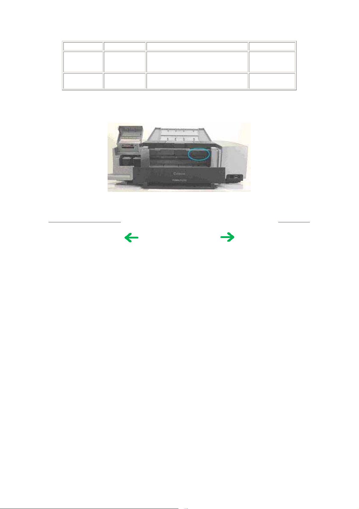
1-5. Serial Number Location
On the chassis (visible when the front cover is open).
QY9-0057-000 To be applied to the sliding portion of
the carriage, and the platen link.
In common with
other models.
To the table of contents To the top
<Part 1: 1.MAINTENANCE>

2. LIST OF ERROR DISPLAY / INDICATIONS
1-4
Errors and warnings are displayed by the following ways:
1) Operator call errors are indicated by the Alarm LED lit. (In the service mode, the Alarm LED blinks to indicate
errors.)
Service call errors are indicated by the number of cycles the Alarm and Power LEDs blink.
2) Errors and warnings are displayed on the LCD on the operation panel.
3) Warnings are displayed on the MP driver Status Monitor.
2-1. Operator Call Errors (by Alarm LED Lit in Orange)
Alarm LED
blinking in
LCD Message
There is no paper.
Load paper and press
[OK].
The paper is jammed.
Clear the paper and
press [OK].
Ink has run out.
Replace the ink
cartridge and close
the cover.
U041
The following ink
cartridge cannot be
recognized.
U051 / U059
The following ink
cartridge cannot be
recognized.
U052
The following ink
cartridge cannot be
recognized.
U140
Some ink cartridge
are not installed in
place.
U075
Some ink cartridge
are not installed in
place.
U076
The following ink
cartridge cannot be
recognized.
U053
The waste ink - Warning: The waste Pressing the OK button The service call error,
orange (in the
service mode
Error [Error code]
only)
2 times
3 times
- No ink. [1600] Replace the empty ink
5 times
15 times
-
7 times
7 times
4 times
No paper. (ASF)
[1000]
Paper jam. [1300] Remove the jammed
Ink cartridge not
installed. [1401]
Ink cartridge not for
this model installed.
[1485]
Ink cartridge not
installed. [1682]
Ink cartridge not for
this model installed.
[1684]
Multiple ink cartridges
of the same color
installed. [1687]
Ink cartridge in a
wrong position. [1686]
Improper installation
of an ink cartridge.
[1687]
Set the paper in the ASF,
and press the OK button.
paper, and press the OK
button.
cartridge(s), or press the
OK button.
Confirm that the ink
cartridges are for this
model, install them
properly, then close the
front cover.
Re-install the applicable
ink cartridge(s) properly,
and close the front cover.
Or, with the ink
cartridges installed, turn
the machine off and on
again.
Confirm that the ink
cartridges are for this
model, install them
properly, then close the
front cover.
Replace the wrong ink
cartridge with the correct
one.
Install the ink cartridge
in the correct position.
Re-install the applicable
ink cartridge(s) properly,
and close the front cover.
Solution Remarks
Pressing the OK button will
exit the error without ink
cartridge replacement,
however, ink may run out
during printing.

absorber is almost
1-5
full.
Press [OK] to
continue but early
replacement
recommended. <See
manual>
Incompatible device
detected.
Remove the device.
The following ink
may have run out.
U161
An ink cartridge that
was once empty is
installed.
U162
Auto head align has
failed. Press [OK] and
repeat operation.
<See manual>
Cover is open.
ink absorber becomes
almost full.
[1700 for the main
waste ink absorber,
1710 for the platen
waste ink absorber]
- The connected digital
camera or digital video
camera does not
support Camera Direct
Printing. [2001]
-
-
-
Remaining ink amount
unknown. [1685/1686]
Failed in automatic
print head alignment.
Front cover open.
[1200]
will clear the error, and
enable printing.
*1
At repair
For main waste ink
absorber replacement,
replace
- the bottom case unit, or
- the ink absorber kit
For platen ink absorber
replacement,
replace
- the ink absorber , and
- the ink absorber kit
MP450: QY5-0151).
Remove the cable
between the camera and
the machine, press the
Stop/Reset button, then
re-connect the cable.
A once-used ink
cartridge (except the one
which has been used
until just before
replacement) is installed.
Replace the applicable
ink cartridge with a new
one, or press the OK
button.
Press the OK button to
exit the error, confirm
the following, then do
the print head alignment
again:
- Set A4 or LTR size
plain paper.
- If the ink nozzles are
clogged, cleaning the
ink cartridge.
- If the paper output slot
has been exposed to a
strong light, move the
printer to a darker
location.
Close the front cover.
:
indicating the waste ink
absorber is full, is likely to
occur soon.
Pressing the OK button will
exit the error without ink
cartridge replacement,
however, the function to
detect the remaining ink
amount is disabled.
Press the Stop/Reset button.
- If paper is being fed at
error occurrence, the error
is indicated after the paper
is ejected.
- If the error occurs, the print
head alignment values are
not changed.
- After exit from the error by
the Stop/Reset button, the
automatic print head
alignment will not be redone.
*1: The main waste ink absorber is separate from the platen waste ink absorber. In servicing, replace the waste ink
absorber which becomes full.
[See Section 3
-3. Adjustment / Settings, (6) Service mode, for details.]
2-2. Service Call Errors (by Cyclic Blinking in Orange (Alarm LED) and Green
1-6
(Power LED), or Alarm LED Lit in Orange)
Cycles of blinking in
orange (Alarm LED) and
green (Power LED)
2 times
3 times
4 times
5 times
6 times
7 times
Solution
Error [Error code]
Carriage error [5100] - Carriage unit (QM2-3332)
Paper feed error [6000] - Timing sensor ass'y (QM2-2850)
Purge unit error [5C00] - Carriage unit (QM2-3332)
ASF (cam) sensor error [5700] - Drive ass'y (QM2-3333)
Internal temperature error [5400]
*2
Waste ink absorber full [5B00]
(Replacement of listed parts, which are
likely to be faulty)
- Timing slit strip film (QC1-6015)
- Logic board ass'y (QM2-2840)
- Carriage motor (QM2-2865)
- Timing slit disk film (QC1-4962)
- Feed roller ass'y (QL2-1284)
- Platen (QC1-7503)
- Logic board ass'y (QM2-2840)
- Paper feed motor (QM2-2866)
- Timing slit strip film (QC1-6015)
- Logic board ass'y (QM2-2840)
- Carriage motor (QM2-2865)
- PE sensor ass'y (QM2-2855)
- Pressure roller ass'y (QM2-3337)
- Logic board ass'y (QM2-2840)
Main waste ink absorber:
- Bottom case unit (QM2-3321)
- Ink absorber kit (QY5-0148)
Platen waste ink absorber:
- Ink absorber (QC1-6014)
- Ink absorber kit (QY5-0148)
*1
*1
*1
*1
*3
8 times
9 times
13 times
15 times
17 times
20 times
Continuous alternate
blinking
Lights in orange
*1: Before replacement of the logic board ass'y, check the waste ink amount, and re-set the waste ink amount value
in the replaced logic board.
[See Section 3
*2: The main waste ink absorber is separate from the platen waste ink absorber. In servicing, replace the waste ink
absorber which becomes full.
[See Section 3
*3: Reset the waste ink counter when replacing the bottom case unit. The main and platen waste ink counters can be
reset separately.
[See Section 3
Cartridge temperature rise error [5200] - Print head
- Logic board ass'y (QM2-2840)
EEPROM error [6800]
Paper feed position error [6B00]
USB Host VBUS overcurrent [9000]
Motor driver error [6D00]
Other hardware error [6500]
ROM error
RAM error
-3. Adjustment / Settings, (6) Service mode, for details.]
-3. Adjustment / Settings, (6) Service mode, for details.]
-3. Adjustment / Settings, (6) Service mode, for details.]
- Logic board ass'y (QM2-2840)
- Paper feed motor (QM2-2866)
- Logic board ass'y (QM2-2840)
- Logic board ass'y (QM2-2840)
- Logic board ass'y (QM2-2840)
- Logic board ass'y (QM2-2840)
- Logic board ass'y (QM2-2840)
- Logic board ass'y (QM2-2840)
*1
*1
*1
*1
*1
*1
*1
*1

2-3. Warnings
1-7
Machine (displayed on the LCD):
Displayed warning Remarks
Low ink
Print head temperature rise
Protection of excess rise of the print head
temperature
*1: If the warning is displayed, the carriage does not move to the ink cartridge replacement position when the
scanning unit is opened.
If the print head temperature is high when the scanning unit is opened, the
warning is displayed.
When the print head temperature falls, the warning is released.
If the print head temperature exceeds the specified limit, a Wait is inserted
during printing,
*1
2-4. Troubleshooting by Symptom
Symptom Solution Remarks
The power does not turn on.
The power turns off immediately
after power-on.
Strange noise.
Printing stops mid-way.
Nothing is displayed on the LCD. - Confirm the connection of the LCD,
Faulty operation
A portion of the LCD is not
displayed.
Multiple sheets feed.
Paper does not feed.
Paper feed
problems
Paper feeds at an angle.
No printing, or no color ejected. Replace the
Replace the
- AC adapter, or
- logic board ass'y*1.
Remove foreign material, or attach a
removed part if any.
Replace the logic board ass'y*1.
operation panel, and the logic board
ass'y.
- Replace the
- LCD, or
- logic board ass'y.
- Perform the button and LCD test in
the service mode, and confirm that the
LCD is displayed without any
segments missing.
- Confirm the connection of the LCD,
operation panel, and the logic board
ass'y.
- Replace the
- LCD, or
- logic board ass'y.
Replace the
- drive unit, or
- pressing plate ass'y.
Remove foreign material, or replace the
- drive unit, or
- pressing plate ass'y.
Remove foreign material, or adjust the
paper guide, or replace the
- drive unit, or
- pressing plate ass'y.
- ink cartridge
- logic board ass'y*1,
*2
,

Unsatisfactory
1-8
print quality
Printing is faint, or white lines appear
on printouts even after print head
cleaning.
Line(s) not included in the print data
appears on printouts.
Paper gets smeared.
A part of a line is missing on
printouts.
Color hue is incorrect.
Printing is incorrect.
No ejection of black ink.
Graphic or text is enlarged on
printouts.
- drive unit, or
- cap blade unit.
Remove and re-install the ink
cartridges, or replace the
- ink cartridge*2,
- cap blade unit,
- purge unit, or
- logic board ass'y*1.
Feed several sheets of paper,
perform bottom plate cleaning, or
clean the paper path with cotton swab or
cloth.
Replace the ink cartridge(s)*2.
Replace the ink cartridge*2, or
perform print head alignment.
Replace the logic board ass'y*1.
Replace the ink cartridge(s)*2.
When enlarged in the carriage
movement direction, clean grease or oil
off the timing slit strip film, or replace
the
- timing slit strip film,
- carriage unit, or
- logic board ass'y*1.
When enlarged in the paper feed
direction, clean grease or oil off the
timing slit disk film, or replace the
- timing slit disk film,
- timing sensor unit, or
- logic board ass'y*1.
*1: Before replacement of the logic board ass'y, check the waste ink amount, and re-set the waste ink amount value
on the replaced logic board.
[See Section 3
*2: Replace the print head only after the print head deep cleaning is performed 2 times, and when the problem
persists.
To the table of contents
-3. Adjustment / Settings, (6) Service mode, for details.]
To the top
<Part 1: 2. LIST OF ERROR DISPLAY / INDICATION>

3. REPAIR
p
1-9
3-1. Notes on Service Part Replacement (and Disassembling / Reassembling)
Service part
Logic board ass'y
QM2-2840
Bottom case unit
QM2-3321
Ink absorber
QY5-0148
Notes on replacement
- Before removal of the logic
board ass'y, remove the
power cord, and allow for
approx. 1 minute (for
discharge of capacitor's
accumulated charges), to
prevent damage to the logic
board ass'y.
- After replacement, reset the
waste ink amount data in the
replaced logic board ass'y.
[See 3-3. Adjustment /
Settings, (6) Service mode, for
details.]
Main platen waste ink
absorber
*1
Adjustment / settings Operation check
After replacement:
1. Initialize the EEPROM.
2. Set the destination in the
EEPROM.
3. Set the LCD language.
[See 3-3. Adjustment /
Settings, (6) Service mode,
for details of 1 to 4.]
4. Perform the print head
alignment in the user
mode.
After replacement:
1. Reset the main waste ink
counter.
-3. Adjustment /
[See 3
Settings, (6) Service
mode.]
2. Adjust the head-to-paper
distance.
-3. Adjustment /
[See 3
Settings, (6) Service
mode.]
- EEPROM information
print
- Service test print
- Printing via parallel or
USB connection
- Direct printing from a
digital camera
- Direct printing from a
memory card
- Print Beam printing
- Service test print
- Printing on thick paper
Carriage unit
QM2-3332
Paper feed motor unit
QM2-2866
Timing slit strip film
QC1-6015
Timing slit disk film
QC1-4962
The red screws on both sides
of the main chassis securing
the carriage shaft are allowed
to be loosened only when
replacing the carriage or
removing the main chassis.
Before removing the screws,
mark the original screw
position, and re-fasten them at
the original position.
- The red screws securing the
aper feed motor are allowed
to be loosened. (DO NOT
loosen any other red screws.)
- Upon contact with the film,
wipe the film with ethanol.
- Confirm no grease is on the
film. (Wipe off any grease
thoroughly with ethanol.)
- Do not bend the film
At replacement:
1. Apply grease to the sliding
portions.
[See 3
Settings, (3) Grease
application.]
2. Adjust the distance between
the carriage shaft and the
platen.
[See 3
Settings, (2) Main chassis
and carriage rail
adjustment.]
3. Perform the print head
alignment in the user
mode.
At replacement:
1. Adjust the paper feed
motor.
[See 3
Settings, (1) Paper feed
motor adjustment.]
After replacement:
1. Perform the print head
alignment in the user
mode.
-3. Adjustment /
-3. Adjustment /
-3. Adjustment /
- Printing on thick paper
- Service test print
 Loading...