

Canon DADF-AV1 Service Manual

DADF-AV1
Service Manual
Revision 2.0

1x
1x
Introduction
Introduction
Important Notices
Application
This manual has been issued by Canon Inc. for qualified persons to learn technical theory, installation, maintenance, and repair
of products.
This manual covers all localities where the products are sold. For this reason, there may be information in this manual that does
not apply to your locality.
Corrections
This manual may contain technical inaccuracies or typographical errors due to improvements or changes in products.
When changes occur in applicable products or in the contents of this manual, Canon will release technical information as the
need arises. In the event of major changes in the contents of this manual over a long or short period, Canon will issue a new
edition of this manual.
The following paragraph does not apply to any countries where such provisions are inconsistent with local law.
Trademarks
The product names and company names used in this manual are the registered trademarks of the individual companies.
Copyright
This manual is copyrighted with all rights reserved. Under the copyright laws, this manual may not be copied, reproduced or
translated into another language, in whole or in part, without the consent of Canon Inc.
Copyright CANON INC. 2016
Caution
Use of this manual should be strictly supervised to avoid disclosure of confidential information.
Explanation of Symbols
The following symbols are used throughout this Service Manual.
Symbols Explanation Symbols Explanation
Check.
Remove the claw.
Check visually.
Check a sound. Push the part.
Insert the claw.
1x
1x
1x
1x
1x
1x
1x
1x
Introduction
Symbols Explanation Symbols Explanation
Disconnect the connector. Connect the power cable.
Connect the connector. Disconnect the power cable.
Remove the cable/wire from the
cable guide or wire saddle.
Install the cable/wire to the cable
guide or wire saddle.
Remove the screw.
Install the screw.
Cleaning is needed. Measurement is needed.
The following rules apply throughout this Service Manual:
1. Each chapter contains sections explaining the purpose of specific functions and the relationship between electrical and
mechanical systems with reference to the timing of operation.
In the diagrams, represents the path of mechanical drive; where a signal name accompanies the symbol, the arrow
indicates the direction of the electric signal.
The expression "turn on the power" means flipping on the power switch, closing the front door, and closing the delivery unit
door, which results in supplying the machine with power.
2. In the digital circuits, '1' is used to indicate that the voltage level of a given signal is "High", while '0' is used to indicate "Low".
(The voltage value, however, differs from circuit to circuit.) In addition, the asterisk (*) as in "DRMD*" indicates that the DRMD
signal goes on when '0'.
In practically all cases, the internal mechanisms of a microprocessor cannot be checked in the field. Therefore, the operations
of the microprocessors used in the machines are not discussed: they are explained in terms of from sensors to the input of
the DC controller PCB and from the output of the DC controller PCB to the loads.
The descriptions in this Service Manual are subject to change without notice for product improvement or other purposes, and
major changes will be communicated in the form of Service Information bulletins.
All service persons are expected to have a good understanding of the contents of this Service Manual and all relevant Service
Information bulletins and be able to identify and isolate faults in the machine.
Turn on the power.
Turn off the power.
Loosen the screw.
Tighten the screw.

Contents
Contents
Safety Precautions...............................................................................................1
Notes Before Servicing........................................................................................................................2
Points to Note at Cleaning...................................................................................................................2
Notes on Assembly/Disassembly........................................................................................................2
1. Product Overview.............................................................................................3
Features.............................................................................................................................................4
Specifications.................................................................................................................................5
Name of Parts..................................................................................................................................... 6
External View........................................................................................................................................6
Cross Section ................................................................................................................................... 6
2. Technical Explanation..................................................................................... 7
Basic Configuration............................................................................................................................. 8
Functional Configuration........................................................................................................................8
Electric Circuit Diagram....................................................................................................................... 10
Controls.............................................................................................................................................11
Controls..............................................................................................................................................11
Basic Operation.................................................................................................................................12
Outline............................................................................................................................................... 12
Forward Pickup/Delivery Operation...................................................................................................... 12
Forward Pickup/Reverse Delivery Operation......................................................................................... 13
Document Pickup/Feed.....................................................................................................................18
Basic Operation.................................................................................................................................. 18
Pickup Roller Assembly and Separation Roller......................................................................................19
Document Reversing.........................................................................................................................20
Basic Operation.................................................................................................................................. 20
Document Delivery............................................................................................................................22
Document Detection..........................................................................................................................23
Outline............................................................................................................................................... 23
Initial Document Size Detection............................................................................................................23
Mixed width document size detection....................................................................................................25
Detecting Jams..................................................................................................................................27
Power Supply.................................................................................................................................... 29
Stamp Operation (If equipped with the Stamp Unit)..........................................................................30
Original Output Indicator................................................................................................................... 31
Upgrading..........................................................................................................................................32
Outline............................................................................................................................................... 32
3. Periodical Service.......................................................................................... 33
List of Work for Servicing.................................................................................................................. 34
i

Contents
4. Parts Replacement and Cleaning................................................................. 35
List of Parts....................................................................................................................................... 36
External Cover....................................................................................................................................36
Main Unit............................................................................................................................................37
Consumable Parts Requiring Periodic Replacement and Cleaning Points............................................... 37
List of Clutch, Solenoid, Motor, PCB.....................................................................................................38
List of Sensor......................................................................................................................................39
Other..................................................................................................................................................40
Removing this Machine from the Host Machine................................................................................41
Procedure...........................................................................................................................................41
Actions after Reinstalling the ADF........................................................................................................ 43
External Cover...................................................................................................................................44
Removing the Front Cover...................................................................................................................44
Removing the Rear Cover....................................................................................................................45
Removing the Feeder Cover................................................................................................................ 46
Removing the Inner Cover................................................................................................................... 47
Main Unit........................................................................................................................................... 49
Removing the Feed Assembly..............................................................................................................49
Periodic Replacing Parts, Durable Parts, Cleaning Parts................................................................. 52
Removing the Pickup Roller Assembly..................................................................................................52
Removing the Separation Roller...........................................................................................................53
Replacing the Stamp........................................................................................................................... 53
Removing the Left Hinge..................................................................................................................... 54
Sensor...............................................................................................................................................56
Removing the Different Width Sensor PCB (PCB3)............................................................................... 56
Removing the Sensor (SR1,SR2,SR3)..................................................................................................56
Clutch, Motor, PCB, Other.................................................................................................................61
Removing the Pickup Motor (M1)......................................................................................................... 61
Removing the Read Motor (M2)........................................................................................................... 61
Removing the Pickup Clutch/Registration Clutch (CL1/CL2)...................................................................62
Removing the ADF Driver PCB (PCB1)................................................................................................ 63
Removing the Document Set LED PCB (PCB2).................................................................................... 63
Removing the Right Hinge................................................................................................................... 64
Removing the Platen Roller................................................................................................................. 65
5. Adjustment..................................................................................................... 68
Overview........................................................................................................................................... 69
Adjustment After Replacing the Parts................................................................................................... 69
Adjustment......................................................................................................................................... 69
Preparation or Creation of Test Chart................................................................................................... 69
Basic Adjustment...............................................................................................................................70
Overview of Adjustment.......................................................................................................................70
Adjusting the Height............................................................................................................................ 70
Adjusting the Perpendicularity..............................................................................................................74
Adjusting the Reading Position.............................................................................................................78
Adjusting the Magnification.................................................................................................................. 79
Adjusting the Image Position (Main Scanning Direction).........................................................................80
Adjusting the Image Position (Sub Scanning Direction)..........................................................................81
Adjusting the White Level.................................................................................................................... 82
ii

Contents
6. Installation...................................................................................................... 84
Checking Before Installation..............................................................................................................85
Check Items when Turning OFF the Main Power...................................................................................85
Points to Note on Installation................................................................................................................85
Product Name.....................................................................................................................................85
Unpacking......................................................................................................................................... 86
Unpacking Procedure..........................................................................................................................86
Checking the Contents......................................................................................................................87
Installation Procedure........................................................................................................................88
Installing the DADF............................................................................................................................. 88
Connecting the DADF Cable................................................................................................................91
Installing Hinge Covers........................................................................................................................94
Affixing the Labels (INCH/AB/K Type Only)...........................................................................................94
Cleaning the ADF Scan Glass..............................................................................................................95
Checking After Installation.................................................................................................................96
Disposal Parts.....................................................................................................................................96
Operation Check................................................................................................................................. 96
Adjustment........................................................................................................................................ 97
Overview of Adjustment.......................................................................................................................97
Preparation or Creation of Test Chart................................................................................................... 97
Adjusting the Height............................................................................................................................ 97
Adjusting the Perpendicularity............................................................................................................ 100
Adjusting the Reading Position...........................................................................................................102
Adjusting the Magnification................................................................................................................ 103
Adjusting the Image Position (Main Scanning Direction).......................................................................104
Adjusting the Image Position (Sub Scanning Direction)........................................................................105
Adjusting the White Level...................................................................................................................106
APPENDICES....................................................................................................107
Service Tools...................................................................................................................................108
Solvents and Oils.............................................................................................................................. 108
Special Tools.................................................................................................................................... 108
General Circuit Diagram..................................................................................................................109
General Circuit Diagram (1/1).............................................................................................................109
iii

Safety Precautions
Notes Before Servicing......................... 2
Points to Note at Cleaning.................... 2
Notes on Assembly/Disassembly..........2

Safety Precautions
Notes Before Servicing
CAUTION:
At servicing, be sure to turn off the power source of the host machine according to the specified steps and disconnect the
power plug.
CAUTION:
Do not turn off the power switch when downloading is under way. Turning off the main power switch while downloading is
under way can disable the machine.
Points to Note at Cleaning
CAUTION:
When performing cleaning using organic solvent such as alcohol, be sure to check that the component of solvent is
vaporized completely before assembling.
Notes on Assembly/Disassembly
Follow the items below to assemble/disassemble the device.
1. Disconnect the power plug to avoid any potential dangers during assembling/disassembling works.
2. If not specially instructed, reverse the order of disassembly to reinstall.
3. Ensure to use the right screw type (length, diameter, etc.) at the right position when assembling.
4. To keep electric conduction, binding screws with washers are used to attach the grounding wire and the varistor. Ensure to
use the right screw type when assembling.
5. Unless it is specially needed, do not operate the device with some parts removed.
6. Never remove the paint-locked screws when disassembling.
7. During disassembly, reassembly or transportation of the printer, remove the cartridge if required. When the cartridge is out
of the printer, put it in a protective bag even in a short period of time to prevent the adverse effect of light.
8. When you replace the part that the rating plate or the product code label is attached, be sure to remove the rating plate or
the product code label and put it to the new part.
2

1
Product Overview
Features.............................................. 4
Specifications.................................. 5
Name of Parts....................................... 6

Features
• Improvement of quick-engaging/disengaging the Pickup roller assembly and the Separation roller
• Improvement of paper curl detection by the modification the Document length sensor
• Installation of the Document delivery Lamp function
1. Product Overview
4

1. Product Overview
Specifications
Item Specifications
Document pickup method Automatic pickup and delivery
Document loading direction Face-up
Document loading position Aligned to center
Document separation method Upper separation
Document weight Single -sided
AB configuration: 42 to 128 g/m
(Single-sided one sheet feed: 38 to 128 g/m2)
Inch configuration: 50 to 128 g/m
Double-sided
Black and White mixed
width document
Color mixed width document
50-128 g/m
Same types of paper: 50 to 128 g/m
Different types of paper: 64 to 81 g/m
Same types of paper: 64 to 128 g/m
Different types of paper: 64 to 81 g/m
2
Black and White/Color
mixed
Document longer than
Single-sided one sheet feed: 60 to 90 g/m
432 mm
Document size AB configuration: B6, A5R, A5, B5R, B5, A4R, A4, B4, A3
Inch configuration: 11×17, LGL, LTR, LTRR, STMT, STMTR, 8K, 16K
Width: 140 to 297 mm
Length: 128 to 432 mm
(It is available when the operator holds long documents between 432mm and
630mm.)
Document supply tray capacity
100 sheets (80 g/m2)
Document feeding mode Single-sided/Double-sided
Document size detection Available (Standard size)
Mixed document function Same types mixed width
Yes
document
Different types mixed
Yes
width document
Book document Supported (The document thickness must be 50 mm or less.)
Power supply Supplied from the host machine
Dimensions 565 mm×525 mm×139 mm (W×D×H)
Weight Approx. 8kg
2
2
2
2
2
2
2
5
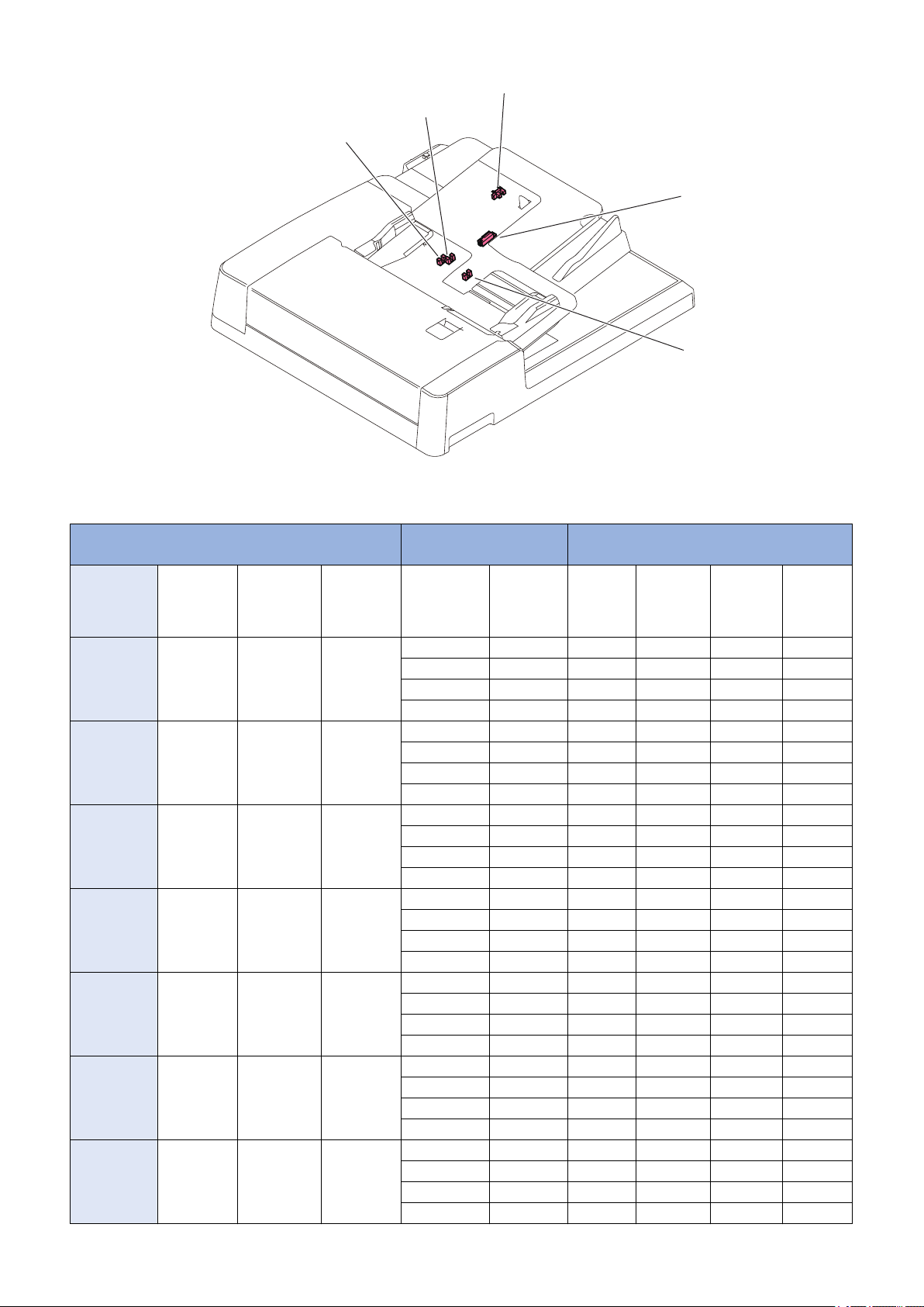
Name of Parts
[1]
[7]
[3] [4]
[2]
[5]
[6]
[3][4][1] [2]
[6][7][9]
[8]
[5]
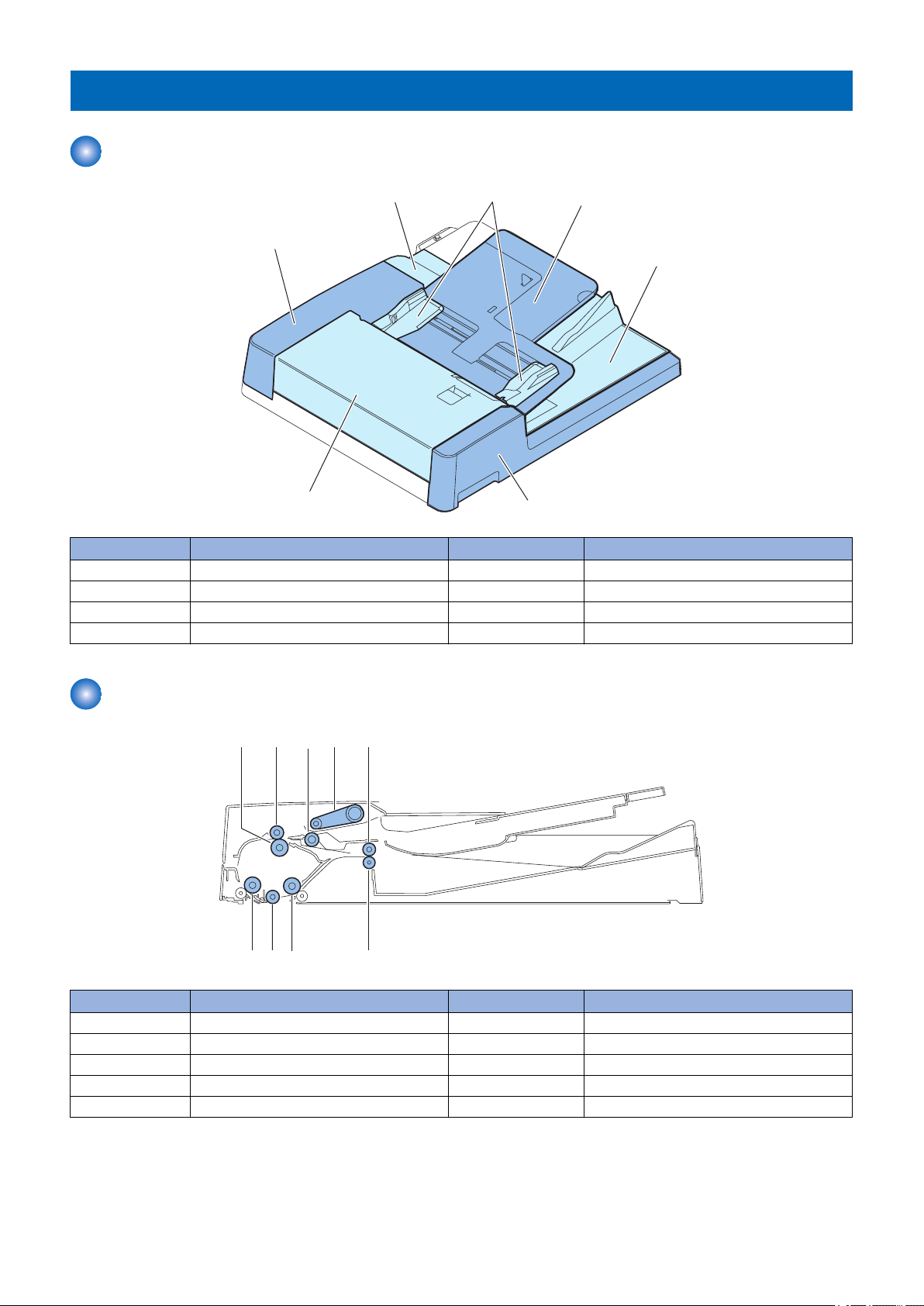
External View
1. Product Overview
No. Name No. Name
[1] Feeder Cover [5] Document supply tray
[2] Front Cover [6] Document delivery assembly
[3] Rear Small Cover [7] Front Cover
[4] Slide guide - -
Cross Section
No. Name No. Name
[1] Lower registration roller [6] Lower delivery reversal roller
[2] Upper registration roller [7] Lead roller 2 (upper)
[3] Pickup roller assembly [8] Platen roller
[4] Separation roller [9] Lead roller 1 (upper)
[5] Upper delivery reversal roller - -
6

Technical
2
Explanation
Basic Configuration...............................8
Controls...............................................11
Basic Operation...................................12
Document Pickup/Feed.......................18
Document Reversing...........................20
Document Delivery..............................22
Document Detection............................23
Detecting Jams................................... 27
Power Supply......................................29
Stamp Operation (If equipped with the
Stamp Unit)......................................30
Original Output Indicator..................... 31
Upgrading............................................32
Basic Configuration
M1
SL1
SL2
PCB1
PCB4
PCB5
PCB2
PCB3
M2
CL1
CL2
[3] [5][4][1] [2]
[6][7][8][9]
[13]
[12]
[10]
[11]
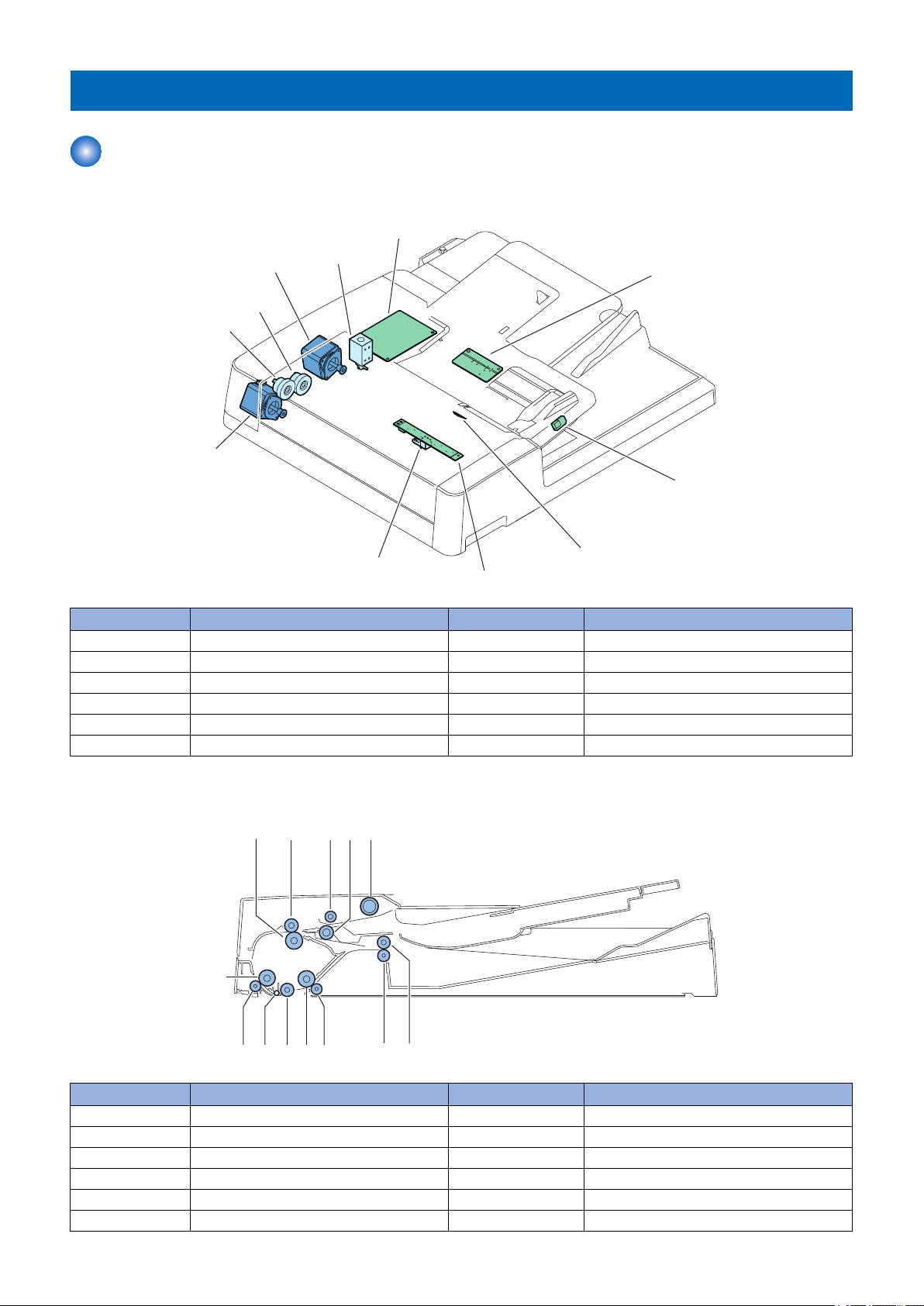
Functional Configuration
■ List of Major Electric Parts
2. Technical Explanation
Symbol Name Symbol Name
CL1 Pickup clutch PCB1 ADF driver PCB
CL2 Registration clutch PCB2 Document set LED PCB
SL1 Release solenoid PCB3 Different width sensor PCB
SL2 Stamp solenoid PCB4 Document width sensor PCB
M1 Pickup motor PCB5 Document delivery LED PCB
M2 Read motor - -
■ Roller Layout
No. Name No. Name
1 Lower registration roller 8 Lead roller 2 (lower)
2 Upper registration roller 9 Lead roller 2 (upper)
3 Feed roller 10 Platen roller
4 Separation roller 11 Lead roller
5 Pickup roller 12 Lead roller 1 (lower)
6 Upper delivery reversal roller 13 Lead roller 1 (upper)
8
No. Name No. Name
SR1SR2
SR3
SR5
SR6
SR7
SR8
SR9/SR10/SR11/SR12
SR13/SR14
SR15
CL1
M1
SL1
M2
CL2
SL2
7 Lower delivery reversal roller - -
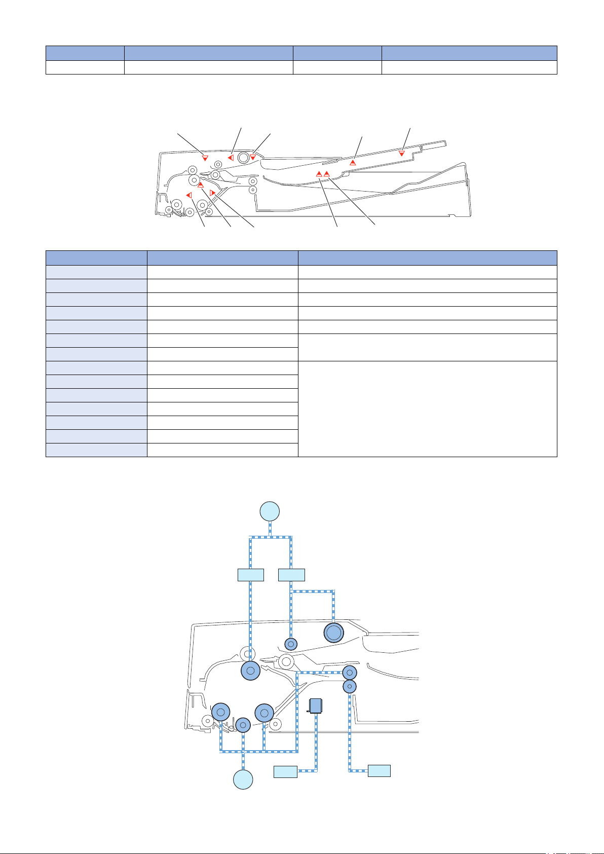
■ Sensor Layout
Symbol Name Detection description
SR1 Registration sensor Registration arch creation timing
SR2 Lead sensor Image Leading start/completion timing
SR3 Delivery reversal sensor Delivery reversal timing
SR5 Document set sensor Document set detection
SR6 Cover open/closed sensor Open/close of Feeder Cover
SR7 Document length sensor 1 Document size detection (length)
SR8 Document length sensor 2
SR9 Different width sensor 1 Document size detection (width)
SR10 Different width sensor 2
SR11 Different width sensor 3
SR12 Different width sensor 4
SR13 Document width sensor 1
SR14 Document width sensor 2
SR15 Document width sensor 3
2. Technical Explanation
■ Drive Configuration
9

ADF driver
PCB
Sensor
Motor
Clutch
Solenoid
Main controller PCBReader controller PCB
2. Technical Explanation
Symbol Name Role
M1 Pickup motor Pickup documents.
M2 Read motor Feeds documents when Stream reading or Delivery.
SL1 Release solenoid Shifts the Lower delivery reversal roller after reversal of a document.
SL2 Stamp solenoid Stamps on a document.
CL1 Pickup clutch Transmit the Pickup motor drive to the Pickup roller and the Feed
roller.
CL2 Registration clutch Transmit the power of the Pickup motor to the Lower registration
roller.
Electric Circuit Diagram
Electric circuits of this machine are controlled by the host machine.
The Main Controller PCB of the host machine detects the input signals from sensors to output DC load drive signal such as
motors, solenoids, and clutches at the predetermined timing.
The ADF driver PCB (PCB1) does not have a memory space. The data, such as the service mode, is stored in the host machine.
10

2. Technical Explanation
Controls
Controls
Item Reference
Basic Operation “Basic Operation” on page 12
Document Pickup/Separation “Document Pickup/Feed” on page 18
Document Reversing “Document Reversing” on page 20
Document Delivery “Document Delivery” on page 22
Document Detection “Document Detection” on page 23
Detecting Jams “Detecting Jams” on page 27
Power Supply “Power Supply” on page 29
Stamp Operation “Stamp Operation (If equipped with the Stamp Unit)” on page 30
Original Output Indicator “Original Output Indicator” on page 31
Upgrading “Upgrading” on page 32
11
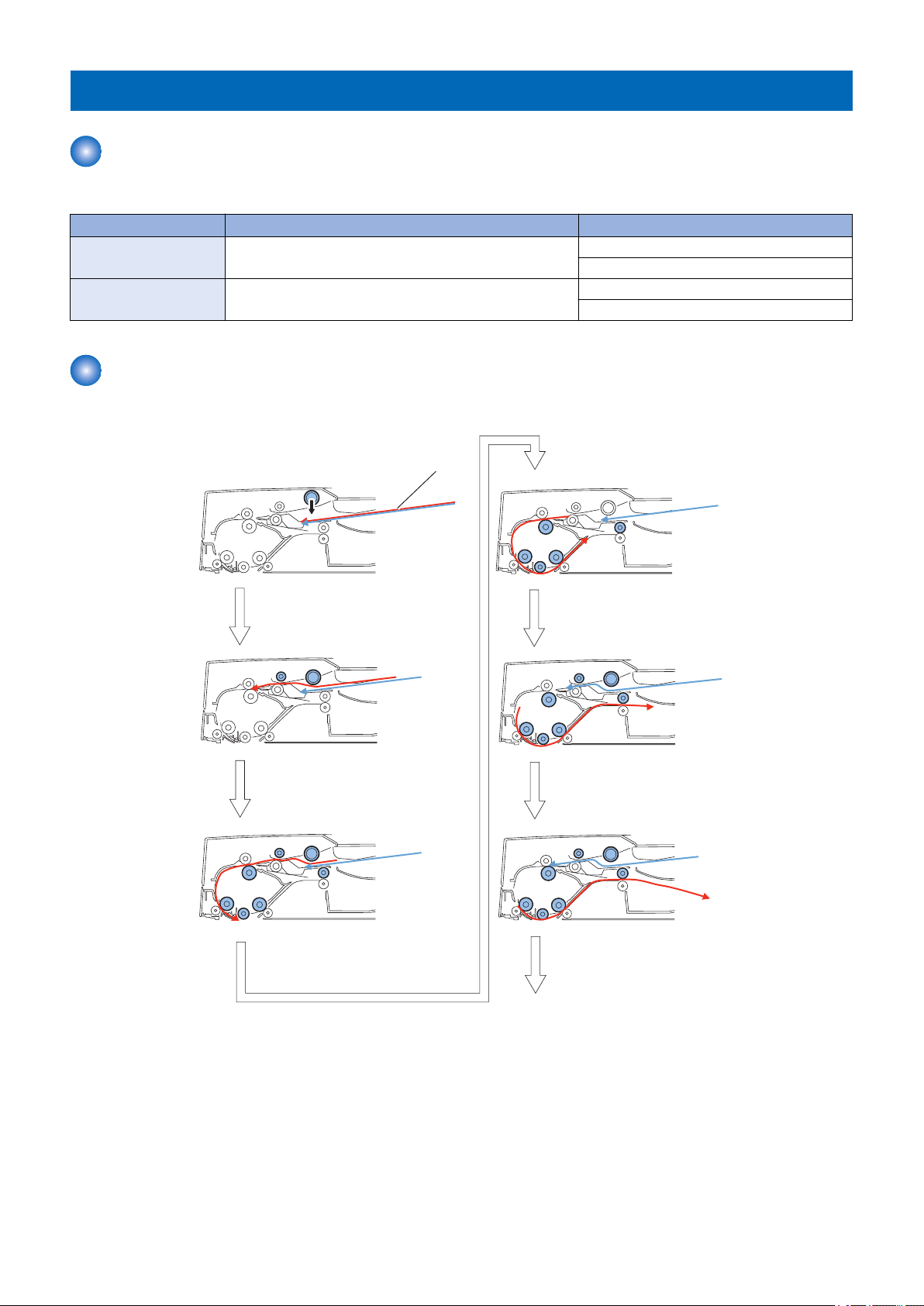
Document
Pickup of first document sheet/
Formation of loop
Start for reading of
the first document sheet
Reading of first document
sheet
Pickup of second document
sheet
Formation of loop
of second document
To next
2. Technical Explanation
Basic Operation
Outline
The ADF has the following operation modes.
Operation mode name Outline of operation Associated print mode
Forward pickup/Delivery Picks up, reads, and then delivers a document. Single-sided document -> Simplex printing
Single-sided document -> Duplex printing
Forward feed/Reverse
delivery
Forward Pickup/Delivery Operation
Simplex read operation (when two document sheets are placed)
Picks up, reads, reverses, and delivers a document. Double-sided document -> Duplex printing
Double-sided document -> Simplex printing
12
Completion of reading of
first document sheet
Completion of reading of
second document sheet
Completion of delivery of
first document sheet
Completion of delivery of
the second document sheet/
End of job
Start of reading of
second document sheet
2. Technical Explanation
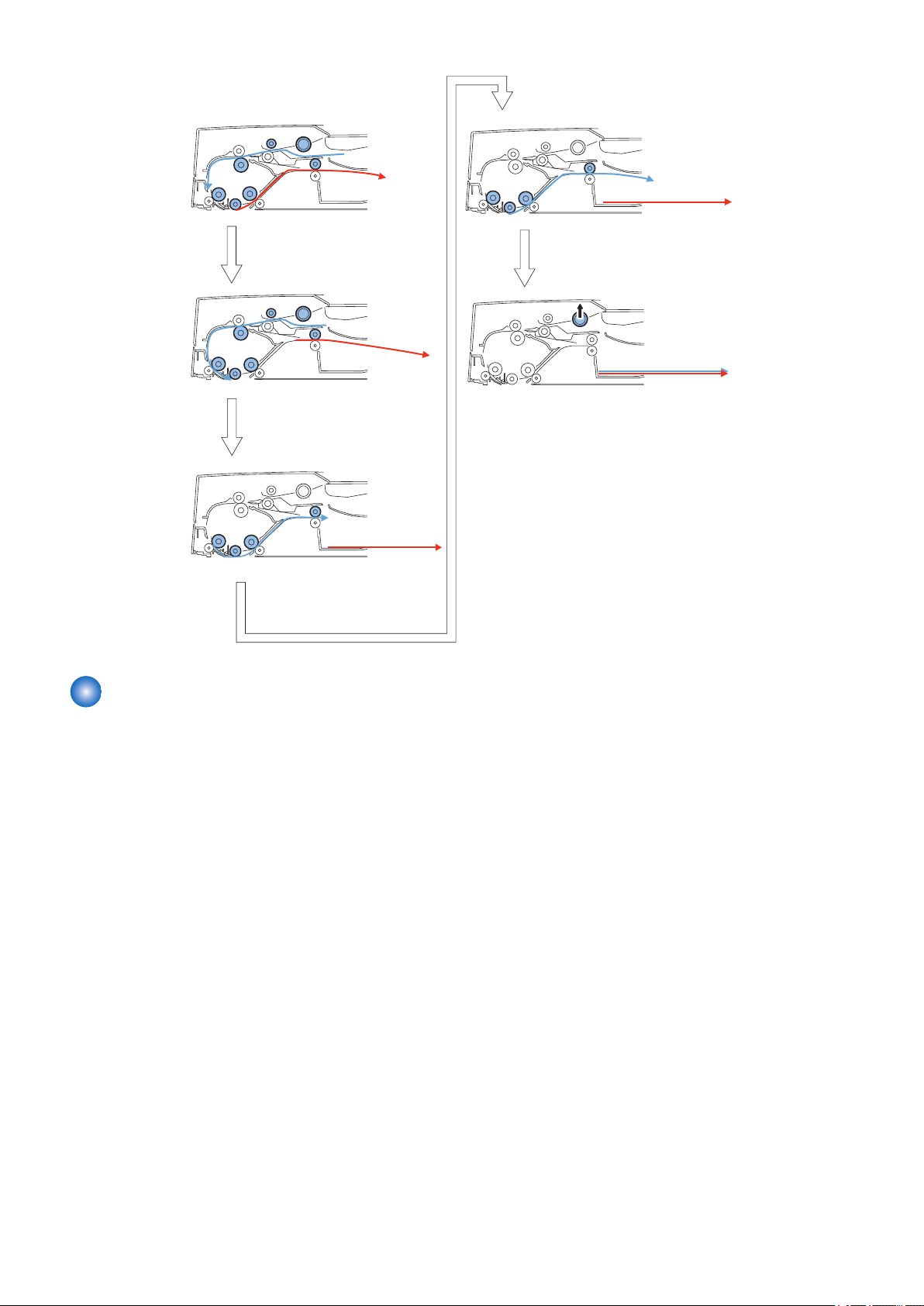
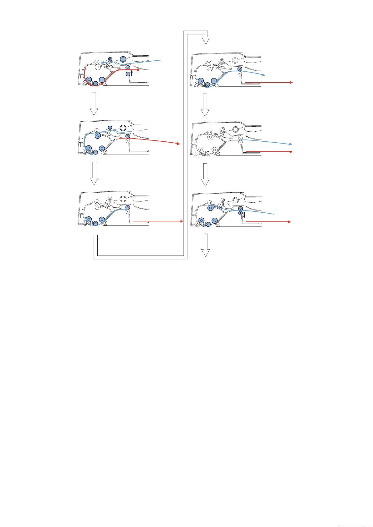
Forward Pickup/Reverse Delivery Operation
Duplex read operation (when two document sheets are placed)
13
Pickup and formation of loop
of first document sheet
Position to start of
reading of first document sheet
Start of reading of front side
of first document sheet
End of reading of
first document sheet
Stop after feeing the first
document sheet to reversal
position
To next
Document
2. Technical Explanation
14
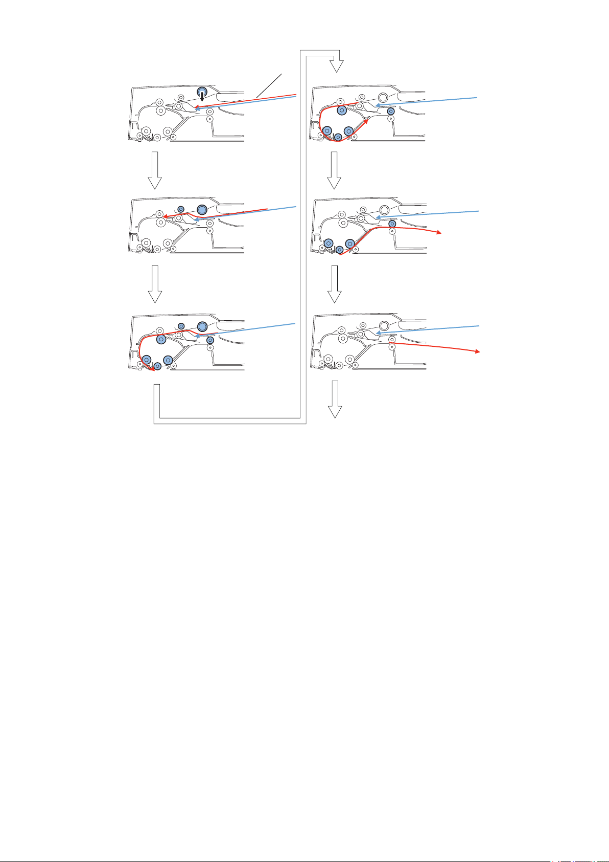
Removal of registration loop of
reverse side of the first document
sheet/Re-pickup/
Release of
the Lower delivery reversal roller
Position to start reading of
reverse side at
the first document sheet
Stop after feeding the first
document sheet to reversal
position
Idle feed of first document
sheet
Removal of idle registration
loop at the first document sheet/
Re-pickup/Release of
the Lower delivery reversal roller
To next
Completion of reading of
reverse side at the first document
sheet/Pressurization of
the Lower delivery reversal roller
2. Technical Explanation
15
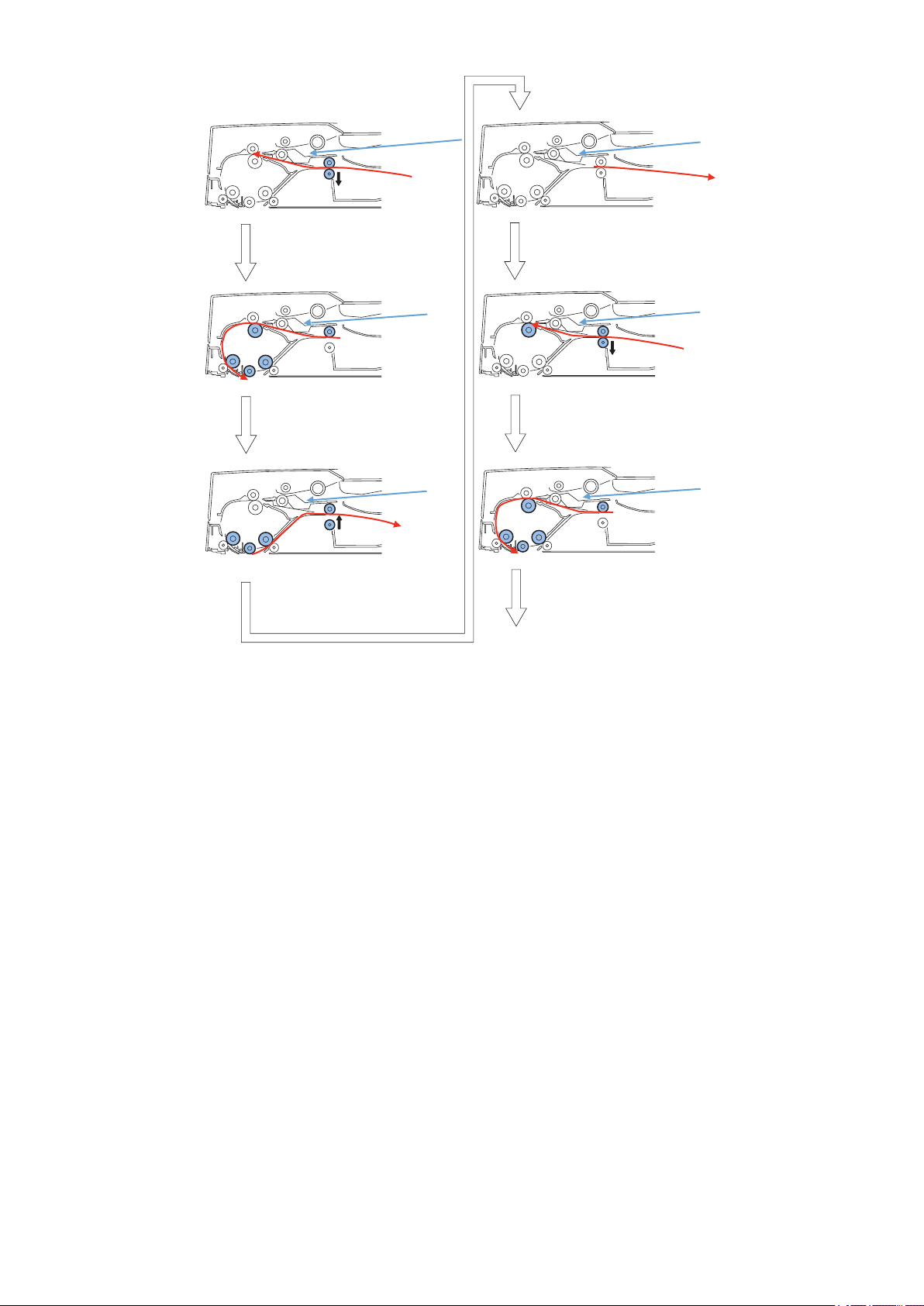
Start of separation at
the seconddocument sheet/
Pressurization of
the Lower delivery reversal roller
Start of reading of top side of
second document sheet
End of reading of front side of
second document sheet
Stop after feeding
the second document sheet
to reversal position
Delivery of first document sheet
Removal of registration loop of
reverse side at the second document
sheet/Re-pickup/Release of
the Lower delivery reversal roller
To next
2. Technical Explanation
16
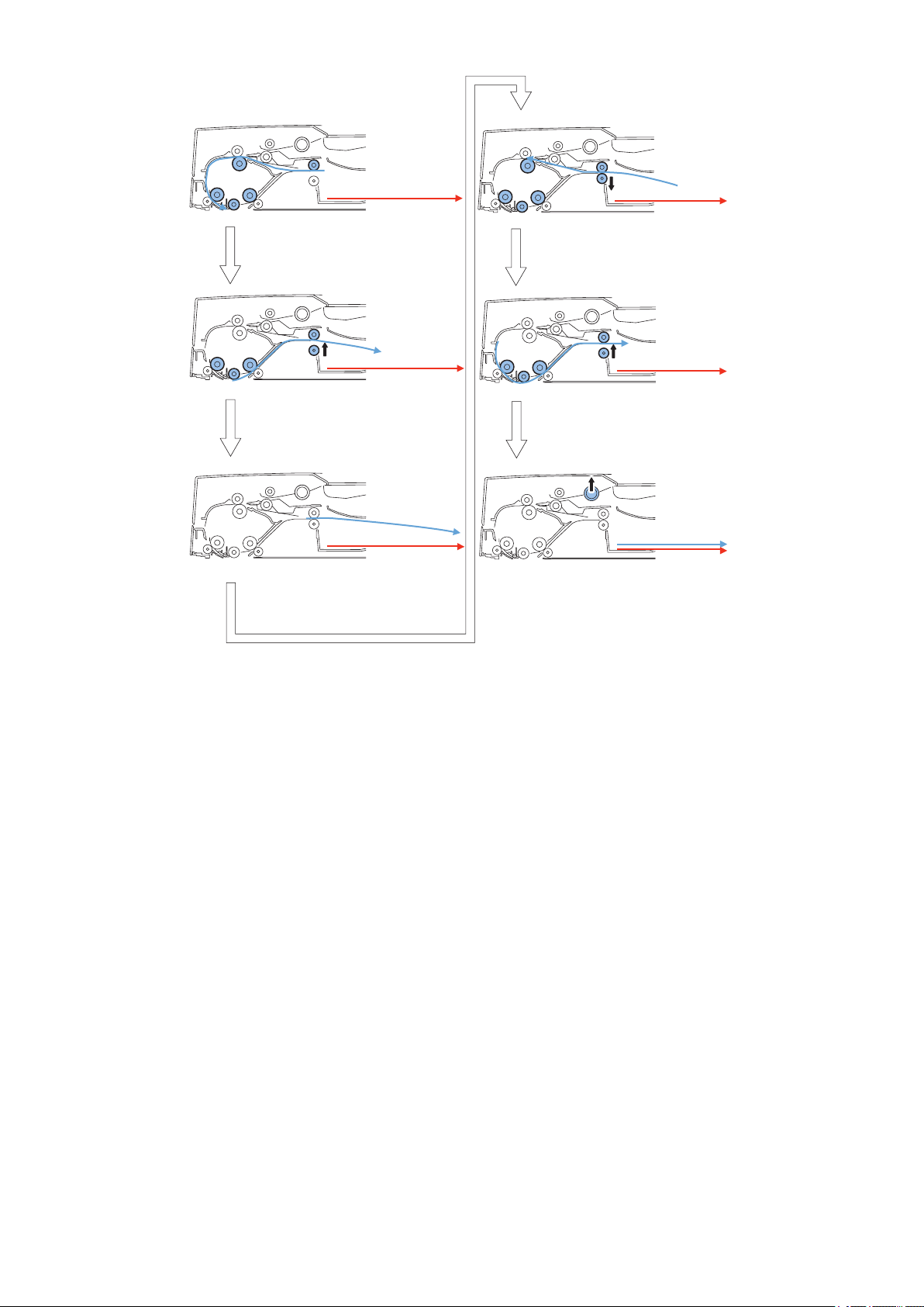
Start of reading of reverse
side of second document sheet
End of reading of reverse
side of second document sheet
Stop after feeding the second
document sheet to reversal position
Removal of idle registration
loop at the second document sheet/
Re-pickup/Release of
the Lower delivery reversal roller
Delivery of second document sheet/
Pressurization at
the Lower delivery reversal roller
Completion of delivery of
second document sheet/end of job
2. Technical Explanation
17
M1
Document
Pickup roller
ศ㞳࣮࣮ࣟࣛ
Stopper
CL1CL1
Pickup roller
ศ㞳࣮࣮ࣟࣛ
Separation roller
M1
Upper/Lower registration roller
Loop
Lower registration roller
Read roller 1
(Upper)
Reading start point
CL2
M1
M2
2. Technical Explanation
Document Pickup/Feed
Basic Operation
After pressing the start key with a document placed on the Document supply tray, a document is picked up in the following
procedure.
■ Pickup Operation
The Pickup motor (M1) drives to lower the Pickup roller assembly through the Pickup clutch (CL1) and then the Pickup roller
rotates to feed a document.
The lock of the stopper is released by linking the Pickup roller assembly. The Separation roller is used to improve the separation
performance while feeding a document.
■ Formation of loop
During Pickup Operation, the Lower registration roller is stopped rotating while moving a document against the Upper/Lower
registration rollers and then form a loop. Thus it prevents a document from skewing.
■ Feed
The Pickup motor (M1) drives the Lower registration roller through the Registration clutch (CL2). Thus a document is fed.
A document is fed to the read wait point when the Read motor (M2) drives the Lead roller 1 (upper).
18

Document glass
Scanner
Platen roller
M2
Pickup clutch(CL1)
Pickup motor(M1)
Stopper
Stopper
Document
Pickup roller
Separation roller
Feed roller
2. Technical Explanation
■ Stream reading
The stream reading starts when the leading edge of a document reaches the reading point and the read start signal is received
from the host machine.
"Stream reading" is a scan function which a document is scanned while feeding along the Document glass. The Scanner which
is fixed under the Document glass reads the image.
A document is fed by the Lead roller 1 (upper) and the Platen roller driven by the Read motor (M2). The read image is stored in
the memory of the host machine.
Pickup Roller Assembly and Separation Roller
The Pickup roller assembly consists of the Pickup roller and the Feed roller.
When the start key is pressed or a document pickup signal is input, the Pickup motor (M1) drives to lower the Pickup roller
assembly through the Pickup clutch (CL1) and then the Pickup roller and the Feed roller rotates to feed a document to the
Registration roller.
The Pickup roller assembly is equipped with stoppers to prevent that a document is inserted deeper than appropriate position.
The Separation roller is used to improve the separation performance while picking up a document.
19
Upper delivery reversal roller
Platen roller
Read roller 2(Upper)
Read roller 1
(Upper)
M2
M2
Delivery reversal sensor(SR3)
SL1
M2
SL1
M2
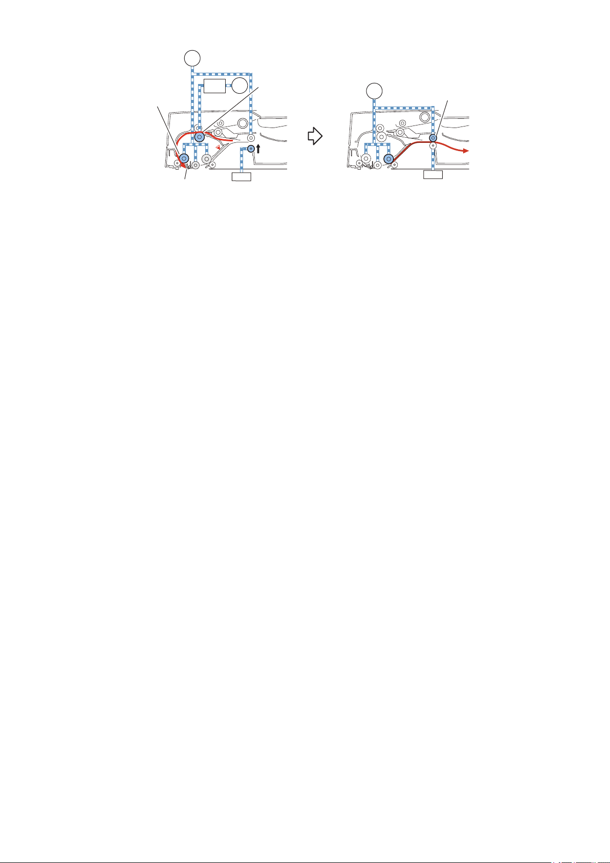
2. Technical Explanation
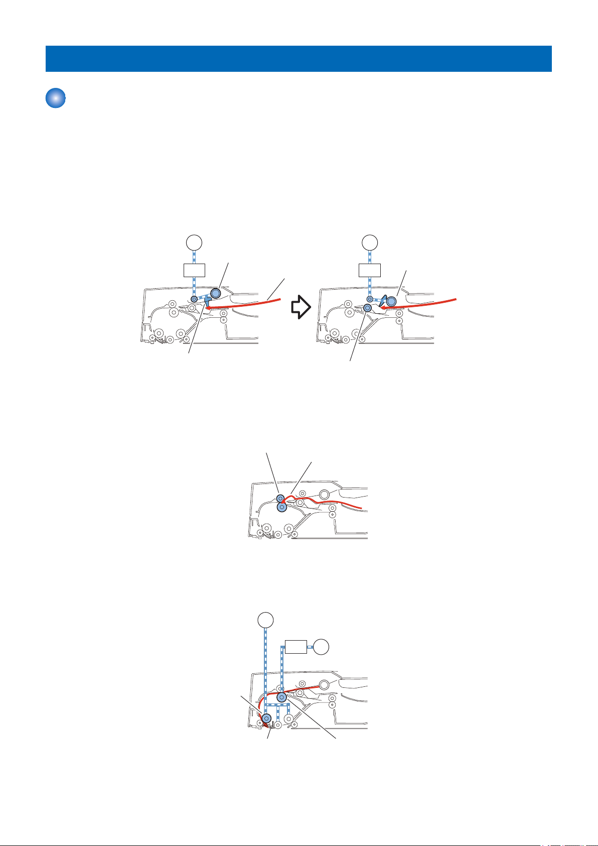
Document Reversing
Basic Operation
There are two types of document reversal operation: one that is performed from the top to the reverse side of the document and
the other that is performed from the reverse side to the top of the document.
Since the basic operation methods are identical, only the reversal operation performed from the reverse side to the top is discussed
below.
■ Top side pickup
The Read motor (M2) drives the Lead roller 1 (upper) and the Platen roller to scan the surface of a document on stream reading.
After completion of scanning, Read motor (M2) drives the Lead roller 2 (upper) and the Upper delivery reversal roller to feed a
document to the reverse point.
■ Reversal/Feed 1
After the trailing edge of a fed document passes the Delivery reversal sensor (SR3), the Read motor (M2) stops.
Thus a document stops at the reverse point. The Read motor (M2) drives in reverse direction to feed a document to the Registration
roller and then it stops. After that, the Release solenoid (SL1) turns on to release the Lower delivery reversal roller.
■ Reversal/Feed 2
The Pickup motor (M1) drives the Lower registration roller through the Registration clutch (CL2) to feed a document to the Read
wait point.
Thus, the document is reversed. After a document is picked up again, turn OFF the Release solenoid (SL1) to pressurize at the
same time that reverse side reading is complete. After that, each operation is performed such as re-reverse, feeding and
delivering.
20
Read roller 1
(Upper)
Upper delivery
reversal roller
SL1
CL2
Reading start point
Lower registration roller
M2
M1
SL1
M2
2. Technical Explanation
21

SL1
Upper delivery reversal roller
SL1
M2
Read roller 2 (Upper)
M2
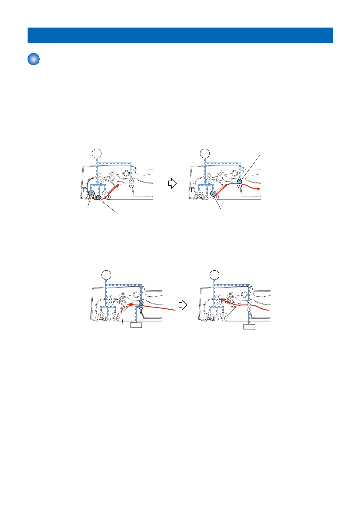
2. Technical Explanation
Document Delivery
A document is delivered by the Lead roller 2 (upper) and the Upper delivery reversal roller driven by the Read motor (M2).
22

Document Detection
Outline
This machine detects a document using either of the two methods depending on the print mode.
• Normal print mode (other than mixed size print mode and banner paper mode)
• Mixed size print mode and banner paper mode
Normal print mode
Function Description Symbol
Document presence/absence detection Detects document existence on the Document sup-
ply tray.
Initial document size absence
detection
Mixed size print mode and banner paper mode
Length Detects document length on the Document supply
tray.
Width Detects the document width on the Document sup-
ply tray.
2. Technical Explanation
Document set sensor(SR5)
Document length sensor 1/2
(SR7/SR8)
Document width sensor1/2/3
(SR13/SR14/SR15)
Function Description Symbol
Document presence/absence detection Detects document existence on the Document sup-
ply tray.
Mixed width document size detection
Length Document length is detected while feeding. Registration sensor (SR1)
Width Detects the maximum document width on the
Document supply tray.
Document width is detected while feeding. Different width sensor 1/2/3/4
Document set sensor (SR5)
Read sensor (SR2)
Document width sensor1/2/3
(SR13/SR14/SR15)
(SR9/SR10/SR11/SR12)
Initial Document Size Detection
Initial document size is detected when a document is placed on the Document supply tray. The Document length sensor 1/2 (SR7/
SR8) and the Document width sensor 1/2/3 (SR13/SR14/SR15) are used for the detection.
The light shading detects document length whose sensor is the Document length sensor 1/2 (SR7/SR8).
Document width is detected by the Document width sensor 1/2/3 (SR13/SR14/SR15) which performs by light prevention plate
connected with the Slide guide adjustment.
Document sizes are determined by combination of ON/OFF states of these sensors.
The Document length sensor 1 (SR7) is a Reflection Sensor which is available to detect the length of a document in case that
the curled paper is placed on the document pickup tray.
23
SR8
SR7
SR13
SR15
SR14
2. Technical Explanation
The following table shows the relationship among length detection sensor signals, document widths, and initial document sizes.
Document width detection Document length detec-
Detected size
tion
Width (mm) Document
width sensor
1 (SR13)
143.9 or less OFF OFF OFF ON ON - - STMTR A5R
More than
143.9 and
165.0 or less
More than
165.0 and
196.0 or less
More than
196.0 and
213.9 or less
More than
213.9 and
236.5 or less
More than
236.5 and
263.5 or less
More than
263.5 and
288.2 or less
OFF ON ON ON ON - - A5R A5R
OFF OFF ON ON ON - - B5R B5R
ON OFF ON ON ON - - A4R A4R
ON ON ON ON ON - LGL LGL A4R
ON OFF OFF ON ON B4 - B4 B4
ON ON OFF ON ON - 11 × 17 11 × 17 K8
Document
width sensor
2 Document
(SR14)
Document
width sensor
3 (SR15)
Document
length sensor
1 (SR7)
OFF ON - - STMTR A5R
ON OFF - - STMTR A5R
OFF OFF - STMTR STMTR A5R
OFF ON - - A5R A5R
ON OFF - - A5R A5R
OFF OFF A5R - A5R A5R
OFF ON - - B5R B5R
ON OFF B5R - B5R B5R
OFF OFF B6 - B6 B6
OFF ON - - A4R A4R
ON OFF A4R - A4R A4R
OFF OFF A5 - A5 A5
OFF ON - - LGL A4R
ON OFF - LTRR LTRR A4R
OFF OFF - STMT STMT A5
OFF ON - - B4 B4
ON OFF - - B4 B4
OFF OFF B5 - B5 B5
OFF ON - 11 × 17 11 × 17 K8
ON OFF - 11 × 17 11 × 17 K8
OFF OFF - LTR LTR K16
Document
length sensor 2 (SR8)
AB INCH AB/INCH AB/K
24
 Loading...