


Manual de Instrucciones |
Modelo RN1545 |
Notas
8-Sp
Operating Instructions |
Model RN1545 |
Please read and save these instructions. Read carefully before attempting to assemble, install, operate or maintain the product described. Protect yourself and others by observing all safety information. Failure to comply with instructions could result in personal injury, death and/or property damage! Retain instructions for future reference.
Coil Roofing
TM Nailer
BUILT TO LAST
Table Of Contents
General Safety . . . . . . . . . . . . . .1-2
Specifications . . . . . . . . . . . . . . . .2
Contact Trip Safety Mechanism . .3
Operating The Nailer . . . . . . . . .3-5
Troubleshooting . . . . . . . . . . . . . .6
Warranty . . . . . . . . . . . . . . . . . . . .7
Description
This nailer is designed for roofing (asphalt and fiberglass shingles), reroofing, and sheathing installation. Features include: convenient top loading magazine which holds up to 120 nails, an adjustable shingle guide, a rubber handle grip, and an adjustable depth of drive mechanism.
General Safety Information
This manual contains safety, operational and maintenance information.
Read this manual and understand all safety warnings and instructions
before operating the nail- MANUAL er. Contact your Campbell Hausfeld representative if
you have any questions.
OPERATOR’S RESPONSIBILITY:
Before operating the nailer, read and understand all safety warnings and labels. Follow the operating instructions outlined in this manual.
EMPLOYER’S RESPONSIBILITY:
Distribute this instruction manual to all users before allowing use of the nailer. Ensure all operators read, understand and follow all safety warnings, labels and instructions outlined in this manual.
Danger indicates an imminently
hazardous situation which, if not avoided, WILL result in death or serious injury.
●Do not use any type of flammable gases or oxygen as a power source
for the nailer. Use fil-
tered, lubricated, regulated compressed air
only. Use of a compressed gas instead of compressed air may
cause the nailer to explode which will cause death or serious personal injury.
●Do not exceed maximum operating pres-
sure of the nailer (115 psi). The nailer will
not function properly. Do not use a com-
pressed air source capable of more than 200 psi. The nailer could explode which will cause death or serious personal injury.
● Never use gasoline or
other flammable liquids to clean the nail-
er. Never use the nailer in the presence of
flammable liquids or gases. Vapors could ignite by a spark and cause an explosion which will result in death or serious personal injury.
● Always remain in a firmly balanced position when using or handling the nailer.
●Do not modify or disable the Work Contact Element
(WCE). Do not tie or tape the WCE or trigger in a
depressed position. Death or serious personal injury could result.
●Do not touch the trigger unless driving nails. Never attach air line to nailer or carry nailer while touching the trigger. The
tool could eject a fastener which will result in death or serious personal injury.
Model RN1545 |
DAILY |
OIL |
Locate model and serial number on tool magazine and cap and record below:
Model No. ________________________
Serial No. _________________________
Retain these numbers for future reference.
Warning indicates a potentially
hazardous situation which, if not avoided, COULD result in death or serious injury.
● Always
disconnect nailer from
air line before
clearing jams, adjusting or servicing the nailer, relocating the nailer, or when the nailer is not in use. Always reconnect the air line BEFORE loading any fasteners. The nailer could eject a fastener causing death or serious personal injury.
●Protect your eyes and ears. Wear Z87 safety glasses, with side shields. Wear hearing protection. Employers
and users are responsible for ensuring the user or anyone near the nailer wears this safety protection. Serious eye injury or permanent hearing loss could result.
Campbell Hausfeld Nailers meet or exceed Industries’ Standards as set forth by the American National |
IN264200AV 4/98 |
Standard Institute/International Staple, Nail and Tool Association in ANSI/ISANTA SNT-101-1993. |
|
© 1998 Campbell Hausfeld |
|
Operating Instructions |
Model RN1545 |
● Do not use a check valve or
any other fitting which
allows air to remain in the
nailer. Death or serious personal injury could occur.
●Never place hands or any other body parts in the nail discharge area of the nailer. The nailer might eject a fas-
tener and could result in death or serious personal injury.
●Never carry the nail-
er by the air hose or pull the hose to move the nailer or a compressor. Keep hoses away from heat, oil and sharp
edges. Replace any hose that is damaged, weak or worn. Personal injury or tool damage could occur.
●Always assume the nailer contains nails. Never use the nailer as a toy. Do not engage in horseplay. Always keep others at a safe distance from the work area in case of accidental discharge of nails. Never point the nailer at anyone. Accidental triggering of the nailer could result in death or serious personal injury.
● Do not drive a nail on top of other nails. The nail could glance and cause death or a serious puncture wound.
● Do not operate or allow anyone
else to operate the nailer if any warnings or warning labels are not legible.
Warnings or warning labels are located on the nailer magazine and body.
●Never leave the nailer unattended or connected to an air compressor when not in use. Serious personal injury can occur if someone picks up and uses the nailer without knowing the correct way to operate the nailer.
●Do not drop or throw the tool. Dropping or throwing the tool can result in damage that will make the tool unusable or unsafe. If the tool has been dropped or thrown, examine the tool closely for bent, cracked or broken parts and air leaks. STOP and repair before using or serious injury could occur.
Caution indicates a potentially haz-
ardous situation which, if not avoided,
MAY result in minor or moderate injury.
●Do not modify or alter the nailer or any nailer parts. Do not use the nailer if any shields or guards are removed or altered. Do not use the nailer as a hammer. Personal injury or tool damage may occur.
●Avoid long extended periods of work with the nailer. Stop using the nailer if you feel pain in hands or arms.
● Always check |
|
|
that the Work |
|
|
Contact |
|
|
Element (WCE) |
|
|
is operating |
|
|
properly. A nail |
|
|
could acciden- |
Movement |
|
tally be driven |
||
|
||
if the WCE is |
|
|
not working properly. Personal |
||
injury may occur (See "Checking the |
||
Work Contact Element" Section). |
||
●Disconnect air supply and release tension from the pusher before attempting to clear jams because fasteners can be ejected from the front of the nailer. Personal injury may occur.
Notice indicates important infor-
mation, that if not followed, MAY cause damage to equipment.
●Avoid using the nailer when the magazine is empty. Accelerated wear on the nailer may occur.
●Clean and check all air supply hoses and fittings before connecting the nailer to an air supply. Replace any damaged or worn hoses or fittings. Tool performance or durability may be reduced.
●Air compressors providing air to the nailer should follow the requirements established by the American National Standards Institute Standard B19.3-1991; Safety Standard for Compressors for Process Industries. Contact your air compressor manufacturer for information.
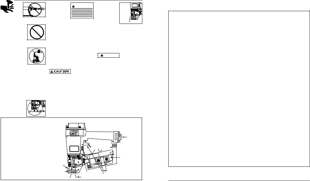
Nailer Components And Specifications
•REQUIRES: 4.5 SCFM with 25 nails per minute @ 90 psi
•AIR INLET: 1/4” NPT
•NAIL SIZE RANGE: 7/8” to1-3/4”
•MAGAZINE CAPACITY:
120 Nails per load
•SHANK DIAMETER: .120" Diameter
•WEIGHT: 5 lbs., 12 oz.
•LENGTH: 18-5/8”
•HEIGHT: 10-1/2”
•MAXIMUM PRESSURE: 115 psi
•PRESSURE RANGE: 60 - 115 psi
Y |
|
|
L |
|
|
I |
|
|
A |
Air Inlet |
|
D |
||
OIL |
||
|


 Magazine Cover
Magazine
Debris Shield

 Shingle Guide
Work Contact |
Door Latch |
Element |
|
|
Trigger |
|
Nail Discharge Area |
Manual de Instrucciones |
Modelo RN1545 |
|
|
Garantía Limitada
1.DURACION: A partir de la fecha de compra por el comprador original tal como se especifica a continuación: Productos EstándardUn año, Productos Resistentes-Dos años, Productos RobustosTres años
2.QUIEN OTORGA ESTA GARANTIA (EL GARANTE: Campbell Hausfeld / A Scott Fetzer Company, 100 Production Drive, Harrison, Ohio 45030, Telephone: (800) 543-6400
3.BENEFICIARIO DE ESTA GARANTIA (EL COMPRADOR): El comprador original (que no sea un revendedor) del producto Campbell Hausfeld.
4.PRODUCTOS CUBIERTOS POR ESTA GARANTIA: Todos los compresores de aire portátiles Campbell Hausfeld, herramientas u accesorios neumáticos suministrados o fabricados por el Garante.
5.COBERTURA DE LA GARANTIA: Los defectos de material y fabricación que ocurran dentro del periodo de validez de la garantía.
6.LO QUE NO ESTA CUBIERTO POR ESTA GARANTIA:
A.LAS GARANTIAS IMPLICITAS, INCLUYENDO LAS GARANTIAS DE COMERCIALIDAD Y CONVENIENCIA PARA UN FIN PARTICULAR, TAL COMO SE ESPECIFICA EN EL PARRAFO DE DURACION. Si este producto es empleado para uso comercial, industrial o para renta, la garantía será aplicable por noventa (90) días a partir de la fecha de compra. En algunos estados no se permiten limitaciones a la duración de las garantías implicitas, por lo tanto, en tal caso esta limitación no es aplicable.
B.CUALQUIER PERDIDA DAÑO INCIDENTAL, INDIRECTO O CONSECUENTE QUE PUEDA RESULTAR DE UN DEFECTO, FALLA O MALFUNCIONAMIENTO DEL PRODUCTO CAMBELL HAUSFELD. En algunos estados no se permite la exclusión o limitación de daños incidentales o consecuentes, por lo tanto, en tal caso esta limitación o exclusión no es aplicable.
C.Cualquier falla que resulte de un accidente, abuso, negligencia o incumplimiento de las instrucciones de funcionamiento y uso indicadas en el (los) manual(es) que se adjunta(n) al producto. Un accidente, abuso, negligencia o incumplimiento de las instrucciones de funcionamiento y uso también incluirá la remoción o modificación de cualquiera de los mecanismos de seguridad. Si tales mecanismos de seguridad son removidos o modificados, esta garantía queda nula.
D.Los ajustes normales explicados en el(los) manual(es) que se adjunta(n) al producto
E.Los artículos o servicio normalmente requeridos para el mantenimiento del producto, tales como juntas tóricas, resortes, topes, rejilla protectora, expulsador, etc. Estos artículos de desgaste normal se garantizan por un período de noventa días solamente desda la fecha original de compra.
F.Los artículos o servicios normalmente requeridos para el mantenimiento del producto, tales como lubricantes, filtros y empaques.
7.RESPONSABILIDADES DEL GARANTE BAJO ESTA GARANTIA: Reparar o reemplazar, como lo decida el Garante, los productos o componentes defectuosos dentro del periodo de validez de la garantía.
8.RESPONSABILIDADES DEL COMPRADOR BAJO ESTA GARANTIA:
A.Entregar o enviar el producto o componente Campbell Hausfeld al Centro de Servicio autorizado Campbell Hausfeld más cercano. Los gastos de flete, de haberlos, deben ser pagados por el comprador.
B.Tener cuidado al utilizar el producto, tal como se indica(n) en el (los) manual(es) del propietario.
9.CUANDO EFFECTUARA EL GARANTE LA REPARACION O REEMPLAZO CUBIERTO BAJO ESTA GARANTIA:
A.La reparación o reemplazo dependerá del flujo normal de trabajo del centro de servicio y de la disponibilidad de repuestos.
B.Si el comprador no recibe resultados satisfactorios en el Centro de Servicio a Clientes de Campbell Hausfeld. (Ver Párrafo 2). Garantía limitada es válida sólo en los Estados Unidos y Canada y le otorga derechos legales específicos. Usted también podría tener otros derechos que varían de un Estado a otro o de un país a otro.
Impreso en Taiwan
2 |
7-Sp |
Manual de Instrucciones |
Modelo RN1545 |
|
|
Guía de Diagnóstico de Averías
Deje de usar la clavadora inmediatamente si alguno de los si guientes problemas ocurre. repuestos. Podría resultado le heridas graves. Cualquier reparación o reemplazo de piezas los
debe hacer un técnico calificado personal de un centro autorizado de servicio.
|
Problema |
Causa |
Solución |
|
|
Hay una fuga de aire en el |
Los anillos en O de la cubierta de la válvula del |
Debe reemplazar los anillos en O & chequear el fun- |
|
|
área de la válvula del gatillo |
gatillo están dañados |
cionamiento del elemento de funcionamiento al contacto |
|
|
Hay una fuga de aire entre la |
Los tornillos de la cubierta están flojos |
Debe apretar los tornillos |
|
|
cubierta y la boquilla |
Los anillos en O están dañados |
Debe reemplazar los anillos en O |
|
|
|
La defensa está dañada |
Debe reemplazar la defensa |
|
|
Hay una fuga de aire entre la |
Los tornillos están flojos |
Debe apretar los tornillos |
|
|
cubierta y la tapa |
El empaque está dañado |
Debe reemplazar el empaque |
|
|
|
|
|
|
|
La clavadora deja de clavar un |
La defensa está desgastada |
Debe reemplazar la defensa |
|
|
clavo |
La boquilla está sucia |
Debe limpiar el canal del sistema de impulso |
|
|
|
La suciedad o daños evitan el desplazamiento |
Debe limpiar el cargador |
|
|
|
libre de los clavos o el mecanismo de impulso |
|
|
|
|
en el cargador |
|
|
|
|
El resorte del mecanismo de impulso está dañado |
Debe reemplazar el resorte |
|
|
|
El flujo de aire hacia la clavadora es inadecuado |
Chequée las conexiones, la manguera o el compresor |
|
|
|
El anillo en O del pistón está desgastado o le |
Debe reemplazar los anillos en O. Lubríquelos. |
|
|
|
falta lubricación |
|
|
|
|
Los anillos en O de la válvula del gatillo están |
Debe reemplazar los anillos en O |
|
|
|
dañados |
|
|
|
|
Hay fugas de aire |
Debe apretar los tornillos y las conexiones |
|
|
|
Hay una fuga en el empaque de la tapa |
Debe reemplazar el empaque |
|
|
|
|
|
|
|
La clavadora funciona lenta- |
La clavadora no está bien lubricada |
Necesita lubricar la clavador |
|
|
mente o pierde su potencia |
El resorte de la tapa del cilindro está roto |
Debe reemplazar el resorte |
|
|
|
El orificio de salida de la tapa está obstruído |
Debe reemplazar las partes internas dañadas |
|
|
|
|
|
|
|
Hay clavos atascados en la |
La guía del mecanismo de impulso está desgastada |
Debe reemplazar la guía |
|
|
clavadora |
Los clavos no son del tamaño adecuado. |
Debe usar los clavos recomendados para esta clavadora |
|
|
|
Los clavos están doblados |
Reemplácelos con clavos en buenas condiciones |
|
|
|
Los tornillos del cargador o de la boquilla están flojos |
Debe apretar los tornillos |
|
|
|
El mecanismo de impulso está dañado |
Debe reemplazar el mecanismo de impulse de clavos |
|
|
|
|
|
|
|
Hay una fuga de aire en el |
Los anillos en O o los sellos están dañados |
Debe reemplazar los anillos en O o los sellos |
|
|
vástago de la válvula del gatillo |
|
|
|
|
|
|
|
|
|
|
CLAVADORES DE BOBINA |
|
|
|
El clavador omite clavar un |
Pistón de alimentación de clavos está seco |
Lubricar el pistón con lubricante extraligero |
|
|
clavo o no alimenta los clavos |
Juntas tóricas dañadas enel pistón de ali- |
Reemplazar las juntas tóricas. Revisar el tope y el resorte. |
|
|
adecuadamente |
|||
|
mentación de clavos. |
Lubricar el conjunto |
||
|
|
|||
|
|
Verificar atascamiento del trinquete |
Verificar el trinquete y el resorte de la puerta |
|
|
|
Parte inferior del cargardor no está ajustada |
La parte inferior del cargador debe ser ajustada de acuer- |
|
|
|
correctamente |
do al largo de los clavos usados |
|
|
|
Alambres soldados en la bobina de clavos están |
No utilice los clavos |
|
|
|
rotos |
|
|
|
|
|
|
|
|
Los clavos están bloqueados en |
Tamaño incorrecto de los clavos |
Debe usar los clavos recomendados para el clavador |
|
|
el cargador |
Alambres soldados en la bobina de clavos están |
No utilice los clavos |
|
|
|
|||
|
|
rotos |
|
|
6-Sp
Operating Instructions |
Model RN1545 |
Operating The Nailer
Read this manual and understand all safety warnings and instructions before operating the nailer.
LUBRICATION
This nailer requires lubrication before using the nailer for the first time and before each use. If an inline oiler is used, manual lubrication through the air inlet is not required on a daily basis.
The work surface can become damaged by excessive lubrication. Proper
lubrication is the owner’s responsibility. Failure to lubricate the nailer properly will dramatically shorten the life of the nailer and void your warranty.
1. |
Disconnect |
|
|
the air supply |
LY |
|
DAI |
|
|
|
OIL |
|
from the nail- |
|
|
er to add |
|
|
lubricant. |
|
2. Turn the nailer
OIL
so the air inlet is facing up. Place 4-5 drops of 30 W non-
detergent oil into air inlet. Do not use detergent oils, oil additives, or air tool oils. Air tool oils contain solvents which will damage the nailer's internal components.
3. |
After adding oil, |
|
|
run nailer briefly. |
OIL |
|
|
LY |
|
|
DAI |
|
Wipe off any |
|
|
excess oil from |
|
|
the cap exhaust. |
|
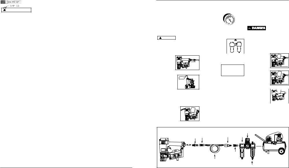
RECOMMENDED HOOKUP
The illustration below shows the recommended hookup for the nailer.
1. The air com- |
|
|
|
|
|
|
60 PSI |
||
pressor must be |
|
|
Min. |
|
able to main- |
|
|
|
|
|
115 PSI |
|
||
tain a minimum |
|
|
||
|
Max. |
|
||
of 60 PSI when |
|
|
||
|
|
|
|
|
|
|
|
|
|
the nailer is being used. An inade- |
||||
quate air supply can cause a loss of |
||||
power and inconsistent |
|
|
|
|
driving. |
|
|
|
|
2. An oiler can be 

 used to provide oil


 circulation through


 the nailer. A filter
 can be used to
  remove liquid and solid impurities which can rust or “gum up” internal parts of the nailer.
3.Use 3/8” air hoses with a minimum working pres-
sure of 200 psi. Use 1/2” air hoses for 50’ run or longer. For better performance, install a 3/8” quick plug (1/4” NPT threads) with an inside diameter of .315” (8mm) on the nailer and a 3/8” quick coupler on the air hose.
4.Use a pressure regulator on the compressor, with an operating pressure of 0 - 125 PSI. A pressure regulator is required to control the operating pressure of the nailer between 60 and 115 psi.
CONTACT TRIP SAFETY MECHANISM
The RN1545 Coil Roofing Nailer is equipped with a contact trip safety mechanism. When both the trigger and the work contact element are depressed, a fastener will be driven.
METHODS OF OPERATING A CONTACT TRIP NAILER:
 Do not touch the trigger unless driving
nails. Never attach air line or carry nailer while touching the trigger. The tool could eject a fastener which will result in death or serious personal injury.
SINGLE NAIL OPERATION
This method is preferred for slower and more precise nail placement.
a. |
Release trigger |
|
|
and place nose of |
Y |
|
DAILDAILY |
|
|
OILOIL |
|
|
tool against work |
|
|
surface. |
|
b. Depress the work |
|
|
|
contact element |
OIOILL |
|
|
LY |
|
|
DAIDAILY |
|
against work |
|
|
surface and pull |
|
|
trigger to drive a |
|
|
fastener. |
|
c. Use caution to pre-  vent tool from dri-


ving a second nail
as a result of nailer 


 recoil. Release


 trigger and lift
  tool completely from work surface as tool recoils after each nail is driven.
Recommended Hookup |
|
|
Regulator |
|
Quick |
Quick |
Quick Plug |
||
|
||||
(Optional) |
Oiler |
|||
Plug |
Coupler |
|||
Y |
|
|
|
|
IL |
|
|
|
|
DA |
|
|
|
|
L |
|
|
|
|
OI |
|
|
|
|
|
|
Quick |
|
|
|
|
Coupler |
|
|
|
|
(Optional) |
|
|
|
|
Air |
|
|
|
|
Hose |
|
|
|
|
|
Filter |
|
|
|
3 |
|
Operating Instructions |
Model RN1545 |
|
|
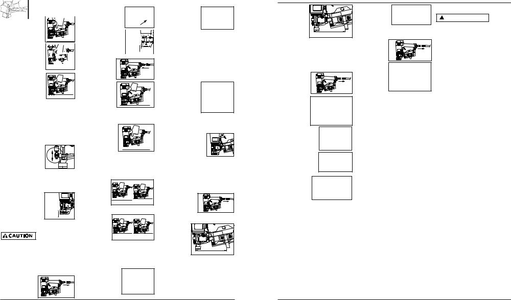
MULTIPLE NAIL OPERATION
This method is preferred for faster, less precise nail placement. 
a. Depress trigger while holding tool above work surface.
b. Depress work contact  element by tapping


 the nose of tool


 against work surface


 in a bouncing


 motion.
2. Remove all nails from the magazine (see Loading/ Unloading).
3. Make sure the trigger  and Work Contact


 Element (WCE) move


 freely up and down


 without sticking or Movement
  binding.
4. Reconnect air supply to the nailer.
c. Each time the work |
|
|
|
|
|
contact element is |
|
5. |
Depress the |
|
|
depressed, a fastener |
|
|
|
||
|
|
WCE against the |
|
Y |
|
will be driven. |
|
|
|
DAIL |
|
|
|
|
OIL |
||
|
|
work surface |
|
|
|
|
|
|
|
|
|
|
|
|
without pulling |
|
|
ADJUSTING NAIL PENETRATION |
|
the trigger. The |
|
|
|
|
nailer MUST |
|
|
||
The RN1545 is equipped with an |
|
|
|
||
|
NOT OPERATE. Do not use the tool |
||||
adjustable depth of drive feature. This |
|
||||
|
if it operates without pulling the |
||||
feature allows the user to determine how |
|
||||
|
trigger. Personal injury may result. |
||||
deep the fastener will be driven into the |
|
||||
|
|
|
|
||
work surface. |
|
6. |
Remove the nail- |
|
|
a. Adjust operating pressure so nails are |
|
er from the |
|
|
|
driven consistently. Do not exceed |
|
work surface. |
|
|
|
115 psi. |
|
|
The WCE must |
|
|
b. To adjust depth of |
|
|
return to its |
|
|
|
|
original down |
|
|
|
drive, loosen safety |
|
|
|
|
|
|
|
position. |
|
|
|
assembly lock nuts |
|
|
|
|
|
|
|
Depress the trigger. The nailer |
|||
with a 10mm wrench. |
|
|
|||
|
|
MUST NOT OPERATE. Do not use |
|||
To increase depth of |
|
|
|||
|
|
the tool if it operates while lifted |
|||
drive, adjust safety |
|
|
|||
|
|
from the work surface. Personal |
|||
assembly upward. To decrease depth |
|
||||
of drive, adjust safety assembly down- |
|
injury may result. |
|
|
|
ward. Make certain both lock nuts |
7. |
Pull the |
|
|
|
are tightened securely after each |
|
|
|||
|
trigger and |
|
|
||
adjustment. |
|
|
|
|
|
|
|
depress the |
|
|
|
c. Make sure trigger |
|
|
|
|
|
|
|
WCE against |
|
|
|
and work contact |
|
|
the work |
1. |
2. |
element (WCE) move |
|
|
surface. The |
||
|
|
|
|
||
freely up and down |
|
|
nailer MUST OPERATE. |
|
|
without binding or |
|
8. |
Depress the |
|
|
sticking after each |
Movement |
|
|
||
|
|
|
|||
adjustment. |
|
|
WCE against |
|
|
WORK CONTACT ELEMENT (WCE) |
|
the work sur- |
|
|
|
|
face. Pull the |
|
|
||
|
|
|
|
|
|
Check the opera- |
|
trigger. The |
1. |
2. |
|
tion of the Work |
|
nailer MUST |
|||
|
|
|
|||
Contact Element (WCE) trip mechanism |
|
OPERATE. |
|
|
|
before each use. The WCE must move |
LOADING/UNLOADING THE NAILER |
||||
freely without binding through its entire |
|||||
travel distance. The WCE spring must |
1. |
Always connect the tool to the air |
|||
return the WCE to its fully extended posi- |
|||||
tion after being depressed. Do not oper- |
|
supply before loading fasteners. |
|||
ate the nailer if the WCE trip mechanism is |
2. |
Pull the door |
|
|
|
not operating properly. Personal injury |
|
|
|||
may occur. |
|
|
latch down and |
|
|
1. Disconnect the |
|
|
open the door. |
|
|
|
|
Open magazine |
|
|
|
air supply from |
|
|
|
|
|
|
|
cover. |
|
|
|
the nailer. |
|
|
|
|
|
|
|
|
|
|
|
3.Check the nail platform adjustment.
Change nail platform settings by
pulling up on the post and twisting to the correct setting:
a.7/8" and 1" nails - use top setting.
b.1-1/4" and 1-1/2" nails - use middle setting.
c.1-3/4" nails - use bottom setting.
The nail platform must be set for the length of nails to be used or the nails will not feed properly.
4.Load the coil of nails over the post in the magazine. Make sure to uncoil enough nails to reach the feed pawl. The
first nail should be placed in front of the front tooth on the feed pawl in the driver channel and the nail
heads must be in the slot in the
nose.
5. Close the magazine cover and door latch.
6.Always unload all fasteners before removing tool from service. Unloading is the reverse of loading, except always disconnect the air hose before unloading.
SHINGLE GUIDE ADJUSTMENT
1. Disconnect the
air supply from the nailer.
2. Loosen the two screws on the
shingle guide under the magazine.
3. |
Place the |
|
|
shingle |
|
|
guide |
|
|
against the |
|
|
front edge |
|
|
of the |
|
|
shingle. |
SHINGLE EXPOSURE |
|
|
4.Adjust the shingle guide until the desired shingle exposure is achieved.
5.Tighten the two screws on the shingle guide.
Manual de Instrucciones |
|
|
Modelo RN1545 |
|||
3. |
Coloque la |
|
2. |
Sujete el clavo |
Clavos et Repuestos |
|
|
guía contra |
|
|
con unas pin- |
|
|
|
|
|
|
Use sola- |
||
|
el borde |
|
|
zas y sáquelo |
! ADVERTENCIA |
|
|
|
|
mente |
|||
|
delantero de |
|
|
del clavador. |
|
|
|
la teja. |
|
|
sujetadores Campbell Hausfeld origi- |
||
|
|
|
|
|||
4. |
Ajuste la guía |
SHINGLEExposiciónEXPOSUREpara la teja |
Limpieza del Clavador |
nales (o su equivalente) - (vea la |
||
|
de tejas hasta |
información sobre intercambio de |
||||
|
lograr la exposición deseada para la |
1. |
Desconectar |
sujetadores). Use solamente partes |
||
|
teja. |
|
|
el suministro |
de repuesto Campbell Hausfeld origi- |
|
5. Apriete los dos tornillos de la guía |
|
de aire del |
nales. Nunca substituya las partes. |
|||
|
para tejas de madera. |
|
clavador. |
No use partes modificadas o partes |
||
QUE HACER CUANDO LA CLAVADO- |
2. |
Limpie las |
que no den un rendimiento equiva- |
|||
lente al equipo original. El |
|
|||||
RA TENGA UN CLAVO ATASCADO |
|
acumula- |
|
|||
|
rendimiento de las herramientas, la |
|||||
1. |
Desconecte la |
|
|
ciones de |
||
|
|
seguridad y la duración pueden verse |
||||
|
|
alquitrán con |
||||
|
clavadora de |
|
|
|||
|
|
|
aceite com- |
reducidos. Cuando ordene partes de |
||
|
la fuente de |
|
|
|||
|
|
|
bustible |
repuesto o sujetadores, especifique |
||
|
suministro de |
|
|
|||
|
|
|
kerosén #2 o |
el número de la parte. |
|
|
|
aire. |
|
|
|
||
|
|
|
con combustible diesel. No permita |
Para reparar la clavadora |
||
2. |
Tire el retén |
|
|
|||
|
|
que el combustible penetre en el |
||||
|
de la |
|
|
|
|
|
|
|
|
cilindro del expulsador pues se |
Las reparaciones de la clavadora las |
||
|
portezuela |
|
|
|||
|
|
|
puede causar daño. Seque comple- |
debe hacer SOLAMENTE un técnico cal- |
||
|
hacia abajo y |
|
|
|||
|
|
|
tamente el clavador antes de usarlo. |
|||
|
|
|
ificado que tenga experiencia. |
|||
|
abra la tapa |
|
|
|||
|
|
|
|
|||
|
|
|
|
Para colocarle los sellos |
||
|
del cargador. |
|
|
|
||
3. |
Saque los clavos |
|
Servicio Técnico |
Cada vez que repare una clavadora |
||
|
de la nariz del |
|
Si desea hacer alguna pregunta refer- |
deberá limpiarle y lubricarle las partes |
||
|
clavador. |
|
ente a la reparación u operación de las |
internas. Le recomendamos que use |
||
|
|
|
clavadoras, sírvase llamar a nuestro |
Parker O-lube o un lubricante equiva- |
||
4. |
Sujete el clavo |
|
número especial, 1-800-543-6400. Si |
lente en todos los anillos en O. A cada |
||
|
llama desde Ohio o fuera de los |
anillo en O se le debe dar un baño de |
||||
|
atascado con unas |
|||||
|
Estados Unidos continentales, |
lubricante para anillos antes de insta- |
||||
|
pinzas y extráiga- |
|
||||
|
|
comuníquese con nosotros al |
larlos. Igualmente, deberá ponerle un |
|||
|
lo del clavador. |
|
||||
|
|
1-513-3678-1182. |
poco de aceite a todas las piezas que se |
|||
Metodo alterno: |
|
|||||
|
|
|
||||
|
|
|
mueven y muñones. Finalmente, |
|||
1. |
Inserte un |
|
|
|
||
|
|
|
después de haberla ensamblado y antes |
|||
|
destornillador |
|
|
|
||
|
|
|
|
de probar la herramienta deberá pon- |
||
|
en la nariz del |
|
|
|
||
|
|
|
|
erle unas cuantas gotas de aceite sin |
||
|
clavador. |
|
|
|
||
|
|
|
|
detergente 30W u otro aceite similar, |
||
|
Empuje hacia |
|
|
|
||
|
|
|
|
en las líneas de aire. |
|
|
|
arriba la hoja |
|
|
|
|
|
del expulsador a fin de liberar el clavo atascado.
Clavos
Estos clavos para acabado de Campbell Hausfeld los puede comprar en su tienda más cercana. Si necesita ayuda para encontrar un artículo, comuníquese al 1-800-543-6400. Los clavos de Campbell Hausfeld cumplen o exceden el estándar ASTM F1667
Modelo # |
Largo |
Diámetros |
Tipo de |
Cabeza |
Acabado |
Fusión de |
Clavos por |
Clavos por |
de los vástagos |
espiga |
la bobina |
bobina |
Caja |
||||
|
|
|
|
|
|
|
|
|
FC152200 |
22,2 mm |
.120" |
Lisa |
Redonda |
Galvanizado |
Soldadura |
120 |
7200 |
FC152500 |
2,54 cm |
.120" |
Lisa |
Redonda |
Galvanizado |
Soldadura |
120 |
7200 |
FC153000 |
3,18 cm |
.120" |
Lisa |
Redonda |
Galvanizado |
Soldadura |
120 |
7200 |
FC154000 |
3,81 cm |
.120" |
Lisa |
Redonda |
Galvanizado |
Soldadura |
120 |
7200 |
FC154500 |
4,45 cm |
.120" |
Lisa |
Redonda |
Galvanizado |
Soldadura |
120 |
7200 |
Información de intercambio
Los clavos usados con la clavadora para acabado RN1545 de Campbell Hausfeld también se pueden usar con las clavadoras Rollo de techado ATRO, Bostitch RN45, N12B, Hitachi NV45AB, Porter Cable RN175, Sears 18324 y Senco SCN200R.
4 |
5-Sp |
 Loading...