

General Safety Information
This manual contains safety, operational
and maintenance information.
Read this manual and
understand all safety
warnings and instructions
before operating the nailer.
Contact your Campbell
Hausfeld representative if
you have any questions.
CALIFORNIA PROPOSITION 65
You
can
create dust when you cut,
sand, drill or grind
materials such as wood,
paint, metal, concrete, cement, or other
masonry. This dust often contains
chemicals known to cause cancer, birth
defects, or other reproductive harm.
Wear protective gear.
OPERATOR’S RESPONSIBILITY:
Before operating the nailer, read and
understand all safety warnings and
labels. Follow the operating
instructions outlined in this manual.
EMPLOYER’S RESPONSIBILITY:
Distribute this instruction manual to all
users before allowing use of the nailer.
R
Ensure all operators read, understand
and follow all safety warnings, labels and
instructions outlined in this manual.
Danger indicates
an imminently
hazardous situation which, if not
avoided, WILL result in death or serious
injury.
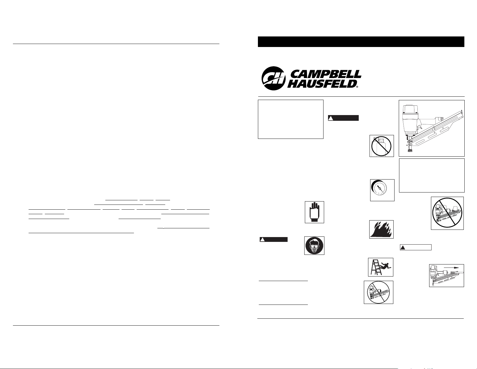
Do not use any type
of flammable gases or
oxygen as a power
source for the nailer.
Use filtered,
lubricated, regulated
compressed air only. Use of a
compressed gas instead of
compressed air may cause the nailer
to explode which will cause death or
serious personal injury.
Do not exceed
maximum operating
pressure of the nailer
(120 psi). The nailer
will not function
properly. Do not use a
compressed air source capable of
more than 200 PSI. The nailer could
explode which will cause death or
serious personal injury.
Never use gasoline or
other flammable
liquids to clean the
nailer. Never use the
nailer in the presence
of flammable liquids or gases. Vapors
could ignite by a spark and cause an
explosion which will result in death
or serious personal injury.
Always remain in a
firmly balanced
position when using
or handling the
nailer.
Do not modify or
disable the Work
Contact Element
(WCE). Do not tie
or tape the WCE
or trigger in a
depressed
position. Death or serious personal
injury could result.
!
DANGER
Operating Instructions Models NS219000, NS289100, NS289500 & NS349000
Do not touch
the trigger
unless driving
nails. Never
attach air line
to nailer or
carry nailer
while touching
the trigger.
The tool could eject a fastener
which will result in death or serious
personal injury.
Warning indicates
a potentially
hazardous situation which, if not
avoided, COULD result in death or
serious injury.
Always
disconnect
nailer from air
line before
clearing jams,
adjusting or
servicing the nailer, relocating the
nailer, or when the nailer is not in
use. Always reconnect the air line
BEFORE loading any fasteners. The
nailer could eject a fastener causing
death or serious personal injury.
!
WARNING
Framing
Nailer
Please read and save these instructions. Read carefully before attempting to assemble, install, operate or maintain the product described.
Protect yourself and others by observing all safety information. Failure to comply with instructions could result in personal injury, death and/or
property damage! Retain instructions for future reference.
IN703802AV 2/07
Campbell Hausfeld Nailers meet or exceed Industries’ Standards as set forth by the American National
Standard Institute/International Staple, Nail and Tool Association in ANSI/ISANTA SNT-101-2002.
© 2007 Campbell Hausfeld
Table Of Contents
General Safety . . . . . . . . . . . . 1-2
Specifications . . . . . . . . . . . . . . 2
Operating The Nailer . . . . . . . . 3
Operational Modes. . . . . . . . . . 4
Troubleshooting . . . . . . . . . . . . 6
Fasteners . . . . . . . . . . . . . . . . . . 7
Warranty . . . . . . . . . . . . . . . . . . 7
Description
This nailer is designed for framing,
trusses, sub-floors, sheathing, exterior
decks, and pallet/create assembly.
Features include: convenient top loading
magazine, no-mar tip, adjustable
exhaust, single cycle trigger, and an
adjustable depth of drive mechanism.
8-Sp
Manual de Instrucciones
120 psi
MAX.
Garantía Limitada
1. DURACION: A partir de la fecha de compra por el comprador original tal como se especifica a continuación:
Productos Estándard (Standard Duty) - Un año, Productos Resistentes (Serious Duty) -Dos años, Productos
Robustos (Extreme Duty) - Tres años.
2. QUIEN OTORGA ESTA GARANTIA (EL GARANTE: Campbell Hausfeld / The Scott Fetzer Company 100
Production Drive, Harrison, Ohio 45030 Teléfono: (800) 543-6400
3. QUIEN RECIBE ESTA GARANTIA (EL COMPRADOR): El comprador original (que no sea un revendedor) del
producto Campbell Hausfeld.
4. PRODUCTOS CUBIERTOS POR ESTA GARANTIA: Cualquier clavadora, grapadora, herramienta neumática,
pistola pulverizadora, inflador o accesorio neumático suministrado o fabricado por el Garante.
5. COBERTURA DE LA GARANTIA: Los defectos substanciales de material y fabricación que ocurran dentro del
período de validez de la garantía.
6. LO QUE NO ESTA CUBIERTO POR ESTA GARANTIA:
A. Las garantías implícitas, incluyendo aquellas de comercialidad E IDONEIDAD PARA FINES
PARTICULARES, ESTAN LIMITADOS A LO ESPECIFICADO EN EL PARRAFO DE DURACION. Si este producto
es empleado para uso comercial, industrial o para renta, la garantía será aplicable por noventa (90) días
a partir de la fecha de compra. En algunos estados no se permiten limitaciones a la duración de las
garantías implícitas, por lo tanto, en tales casos esta limitación no es aplicable.
B. CUALQUIER PERDIDA DAÑO INCIDENTAL, INDIRECTO O CONSECUENTE QUE PUEDA RESULTAR DE UN
DEFECTO, FALLA O MALFUNCIONAMIENTO DEL PRODUCTO CAMPBELL HAUSFELD. En algunos estados
no se permite la exclusión o limitación de daños incidentales o consecuentes, por lo tanto, en tales
casos esta limitación o exclusión no es aplicable
C. Cualquier falla que resulte de un accidente, abuso, negligencia o incumplimiento de las instrucciones de
funcionamiento y uso indicadas en el (los) manual(es) que se adjunta(n) al producto. Dichos accidentes,
abusos por parte del comprador, o falta de operar el producto siguiendo las instrucciones del manual
de instrucciones suministrado también debe incluir la desconexión o modificación de los instrumentos
de seguridad. Si dichos instrumentos de seguridad son desconectados, la garantía quedaría cancelada.
D. Los ajustes normales explicados en el(los) manual(es) suministrado(s) con el producto.
E. Artículos o servicios normalmente requeridos para el mantenimiento del producto, tales como: anillos
en O, resortes, amortiguadores, defensas, hojas de impulsor, fusibles, baterías, empaques, almohadillas
o sellos, boquillas de fluído, agujas, boquillas para rociar arena, lubricantes, mangueras de material,
elementos filtrantes, álabes de motores, abrasivos, hojillas, discos para cortar, cinceles, retenes para
cinceles, cortadores, collarines, mandriles, mordazas para remachadoras, brocas para desarmadores,
almohadillas para lijar, soportes de almohadillas, mecanismo de impacto o cualquier otro artículo
desgastable que no se haya enumerado específicamente. Estos artículos sólo estarán cubiertos bajo esta
garantía por noventa (90) días a partir de la fecha de compra original. Los artículos subrayados sólo
están garantizados por defectos de material o fabricación.
7. RESPONSABILIDADES DEL GARANTE BAJO ESTA GARANTIA: Reparar o reemplazar, como lo decida el
Garante, los productos o componentes que estén defectuosos, se hayan dañado o hayan dejado de
funcionar adecuadamente, durante el período de validez de la garantía
8. RESPONSABILIDADES DEL COMPRADOR BAJO ESTA GARANTIA:
A. Suministrar prueba fechada de compra y la historia de mantenimiento del producto.
B. Entregar o enviar el producto o componente Campbell Hausfeld al Centro de Servicio autorizado
Campbell Hausfeld más cercano. Los gastos de flete, de haberlos, deben ser pagados por el comprador.
C. Seguir las instrucciones sobre operación y mantenimiento del producto, tal como se indica(n) en el (los)
manual(es) del propietario
9. CUANDO EFECTUARA EL GARANTE LA REPARACION O REEMPLAZO CUBIERTO BAJO ESTA GARANTIA: La
reparación o reemplazo dependerá del flujo normal de trabajo del centro de servicio y de la disponibilidad
de repuestos.
Esta garantía limitada es válida sólo en los EE.UU., Canadá y México y otorga derechos legales específicos.
Usted también puede tener otros derechos que varían de un Estado a otro. o de un país a otro.
Locate model and date code on tool
magazine and cap and record below:
Model No. ________________________
Date Code ________________________
Retain these numbers for
future reference.
For parts, product & service information
visit www.chpower.com
BUILT TO LAST
!
DANGE
MANUAL
O
CO
2
2
Protect your eyes and
ears. Wear Z87 safety
glasses, with side
shields. Wear hearing
protection. Employers
and users are responsible for
ensuring the user or anyone near
the nailer wears this safety
protection. Serious eye injury or
permanent hearing loss could
result.
Do not use a
check valve or
any other
fitting which
allows air to
remain in the
nailer. Death or serious personal
injury could occur.
Never place
hands or any
other body
parts in the nail
discharge area
of the nailer.
The nailer might
eject a fastener and could result in
death or serious personal injury.
Never carry the
nailer by the air
hose or pull the
hose to move the
nailer or a
compressor. Keep
hoses away from
heat, oil and sharp edges. Replace
any hose that is damaged, weak or
worn. Personal injury or tool
damage could occur.
Always assume the nailer contains
nails. Never use the nailer as a toy.
Do not engage in horseplay. Always
keep others at a safe distance from
the work area in case of accidental
discharge of nails. Never point the
nailer at anyone. Accidental
triggering of the nailer could result
in death or serious personal injury.
Do not drive a nail on top of other
nails. The nail could glance and
cause death or a serious puncture
wound.
Do not operate or allow anyone else to
operate the nailer if any warnings or
warning labels are
not legible.
Warnings or
warning labels are
located on the
nailer magazine
and body.
Never leave the
nailer
unattended or
connected to an
air compressor
when not in
use. Serious
personal injury can occur if someone
picks up and uses the nailer without
knowing the correct way to operate
the nailer.
Do not drop or throw the tool.
Dropping or throwing the tool can
result in damage that will make the
tool unusable or unsafe. If the tool
has been dropped or thrown,
examine the tool closely for bent,
cracked or broken parts and air
leaks. STOP and repair before using
or serious injury could occur.
Caution indicates a
potentially
hazardous situation which, if not
avoided, MAY result in minor or
moderate injury.
Do not modify or alter the nailer or
any nailer parts. Do not use the nailer
if any shields or guards are removed
or altered. Do not use the nailer as a
hammer. Personal injury or tool
dam.occur.
Avoid long extended periods of work
with the nailer. Stop using the nailer
if you feel pain in hands or arms.
!
CAUTION
Always
check that
the Work
Contact
Element
(WCE) is
operating
properly. A
nail could
accidentally be driven if the WCE is
not working properly. Personal
injury may occur (See "Checking the
Work Contact Element" Section).
Disconnect air supply and release
tension from the pusher before
attempting to clear jams because
fasteners can be ejected from the
front of the nailer. Personal injury
may occur.
Notice indicates
important
information, that if not followed, may
cause damage to equipment.
Avoid using the nailer when the
magazine is empty. Accelerated
wear on the nailer may occur.
Clean and check all air supply hoses
and fittings before connecting the
nailer to an air supply. Replace any
damaged or worn hoses or fittings.
Tool performance or durability may
be reduced.
Air compressors providing air to the
nailer should follow the
requirements established by the
American National Standards
Institute Standard B19.3-1991;
Safety Standard for Compressors for
Process Industries. Contact your air
compressor manufacturer for
information.
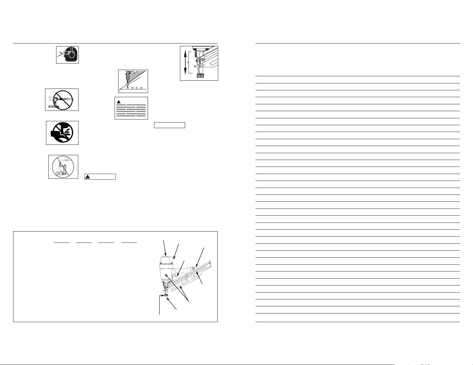
Operating Instructions
NS219000 NS289100 NS289500 NS349000
• REQUIRES
(SCFM with 16 nails 4.1 4.1 4.1 4.1
per minute @ 90 psi)
• AIR INLET 1/4” NPT 1/4” NPT 1/4” NPT 1/4” NPT
• NAIL LENGTH
RANGE 2” to 3
1
⁄
2” 2” to 3
1
⁄
2” 2” to 3
1
⁄
2” 2” to 3
1
⁄
2”
• NAIL SHANK 0.113” to 0.113” to 0.113” to 0.113” to
RANGE 0.131” 0.131” 0.131” 0.131”
• MAGAZINE
CAPACITY 60-75 75-105 75-105 75-105
• WEIGHT 8 lbs. 5 oz. 8 lbs. 15 oz. 7 lbs. 5 oz 8 lbs. 11 oz.
• LENGTH 19.5” 21.75” 21.75” 19.75”
• HEIGHT 15” 15” 15” 15”
• MAX PRESSURE 120 psi 120 psi 120 psi 120 psi
• PRESSURE RANGE 70 - 120 psi 70 - 120 psi 70 - 120 psi 70 - 120 psi
Nailer Components And Specifications
7-Sp
Modelos NS219000, NS289100, NS289500 y NS349000
Adjustable Direction
Exhaust Deflector
Threaded Hole/Tool
Balancer (M8 x 1.25)
Nail Loading
Area
Magazine
Single Cycle
Trigger
Warning Labels
Nail Discharge Area
Work Contact Element
www.chpower.com
Notas
!
WARNING
NOTICE
3
Operating The Nailer
Read this manual and understand all
safety warnings and instructions before
operating the nailer.
LUBRICATION
This nailer requires lubrication before
using the nailer for the first time and
before each use. If an inline oiler is
used, manual lubrication through the
air inlet is not required on a daily basis.
The work surface
can become
damaged by excessive lubrication. Proper
lubrication is the owner’s responsibil- ity.
Failure to lubricate the nailer properly
will dramatically shorten the life of the
nailer and void your warranty.
1. Disconnect
the air
supply from
the nailer to
add
lubricant.
2. Turn the nailer
so the air inlet
is facing up.
Place 4-5 drops
of 30 W nondetergent oil
into air inlet.
Do not use
detergent oils, oil additives, or air
tool oils. Air tool oils contain
solvents which will damage the
nailer’s internal components.
3. After adding oil,
run nailer briefly.
Wipe off any
excess oil from
the cap exhaust.
REMOVING NO-MAR DECKING TIP
1. Disconnect air
supply from
nailer.
2. Remove all fasteners from magazine
(See UNLOADING THE
NAILER).
3. Remove no-mar tip retaining ring.
4. Pry nomar tip
away
from the
work
contact
element.
5. Replace
retaining
ring onto
no-mar
tip, then
store tip
in safe
place for future use.
INSTALLING NO-MAR DECKING TIP
1. Disconnect air
supply from
nailer.
2. Remove all fasteners from magazine
(See UNLOADING THE NAILER).
3. Remove retaining ring from no-mar
tip.
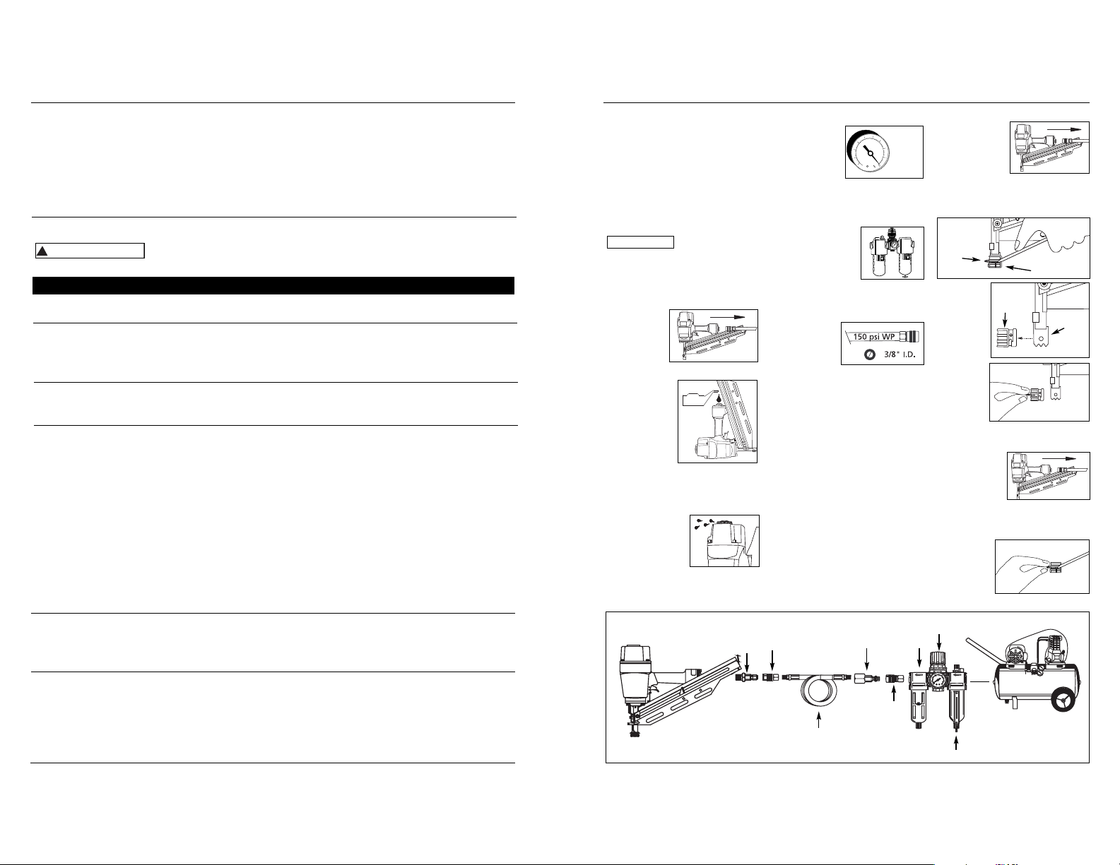
RECOMMENDED HOOKUP
1. The air
compressor
must be able
to maintain a
minimum of 70
psi when the
nailer is being used. An inadequate
air supply can cause a loss of power
and inconsistent driving.
2. An oiler can be
used to provide oil
circulation through
the nailer. A filter
can be used to
remove liquid and
solid impurities which can rust or
“gum up” internal parts of the
nailer.
3. Use 3/8” air
hoses with a
minimum
working
pressure of 150 psi. Use 1/2” air
hoses for 50’ run or longer. For
better performance, install a 3/8”
quick plug (1/4” NPT threads) with
an inside diameter of .315” (8mm)
on the nailer and a 3/8” quick
coupler on the air hose.
4. Use a pressure regulator on the
compressor, with an operating
pressure of 0 - 125 psi. A pressure
regulator is required to control the
operating pressure of the nailer
between 70 and 120 psi.
NO-MAR DECKING TIP
The no-mar decking tip is designed to
eliminate marks caused by the serrated
work contact element (WCE). The nomar tip may be removed if not
required (See REMOVING NO-MAR
DECKING TIP). Use tool in single cycle
mode (SEE OPERATIONAL MODES)
when no-mar tip is in place.
70 psi
Min.
120 psi
Max.
6-Sp
Manual de Instrucciones
Models NS219000, NS289100, NS289500 & NS349000
Retaining
Ring
No-Mar Tip
Work
Contact
Element
NoMar
Tip
Sujetadores
La herramienta NS219000 también coloca sujetadores diseñados para: Sears 18465, Porter Cable FR350, Hitachi NR83A, y Senco
FramePro 702XP, 752XP, Ridgid R350RHA y DeWalt D51844, D51845.
La herramienta NS289100 y NS289500 también coloca sujetadores diseñados para: Sears 18420, Atro Helen 90CH, and
Bostitch F28WW, N100S, N865, N805, N16.
La herramienta NS349000 también coloca sujetadores diseñados para: Porter Cable FC 350A, Hitachi NR83AA2, Senco FramePro
701XP, 751XP , Ridgid R350CHA, DeWalt D51822, D51823 y Paslode F-3505.
Recommended Hookup
Quick
Coupler
Air
Hose
Quick Plug
(Optional)
Quick
Coupler
(Optional)
Oiler
Regulator
Filter
Quick
Plug
Hay una fuga de aire en el
área de la válvula del gatillo
Hay una fuga de aire entre la
cubierta y la boquilla
Hay una fuga de aire entre la
cubierta y la tapa
La clavadora deja de clavar un
clavo
La clavadora funciona
lentamente o pierde su
potencia
Hay clavos atascados en la
clavadora
Los anillos en O de la cubierta de la válvula del
gatillo están dañados
Los tornillos de la cubierta están flojos
Los anillos en O están dañados
La defensa está dañada
Los tornillos están flojos
El empaque está dañado
La defensa está desgastada
La boquilla está sucia
La suciedad o daños evitan el desplazamiento
libre de los clavos o el mecanismo de impulso en
el cargador
El resorte del mecanismo de impulso está dañado
El flujo de aire hacia la clavadora es inadecuado
El anillo en O del pistón está desgastado o le
falta lubricación
Los anillos en O de la válvula del gatillo están
dañados
Hay fugas de aire
Hay una fuga en el empaque de la tapa
La clavadora no está bien lubricada
El resorte de la tapa del cilindro está roto
El orificio de salida de la tapa está obstruído
La guía del mecanismo de impulso está desgastada
Los clavos no son del tamaño adecuado.
Los clavos están doblados
Los tornillos del cargador o de la boquilla están flojos
El mecanismo de impulso está dañado
Debe reemplazar los anillos en O & chequear el
funcionamiento del elemento de funcionamiento al contacto
Debe apretar los tornillos
Debe reemplazar los anillos en O
Debe reemplazar la defensa
Debe apretar los tornillos
Debe reemplazar el empaque
Debe reemplazar la defensa
Debe limpiar el canal del sistema de impulso
Debe limpiar el cargador
Debe reemplazar el resorte
Chequée las conexiones, la manguera o el compresor
Debe reemplazar los anillos en O. Lubríquelos.
Debe reemplazar los anillos en O
Debe apretar los tornillos y las conexiones
Debe reemplazar el empaque
Necesita lubricar la clavador
Debe reemplazar el resorte
Debe reemplazar las partes internas dañadas
Debe reemplazar la guía
Debe usar los clavos recomendados para esta clavadora
Reemplácelos con clavos en buenas condiciones
Debe apretar los tornillos
Debe reemplazar el mecanismo de impulse de clavos
Guía de Diagnóstico de Averías
Deje de usar la clavadora inmediatamente si alguno de los si guientes problemas ocurre.
repuestos. Podría resultado le heridas graves. Cualquier reparación o reemplazo de piezas los
debe hacer un técnico calificado personal de un centro autorizado de servicio.
Problema Causa Solución
www.chpower.com
!
ADVERTENCIA
NOTICE
OIL
Modelos NS219000, NS289100, NS289500 y NS349000
5-Sp
4. Presione el
empujador
con el
enganche
para desenganchar al
empujador.
Asegúrese de que la cabeza del
último clavo esté debajo de la
cabeza del empujador.
CÓMO DESCARGAR LA CLAVADORA
1. Siempre descargue todos los
sujetadores antes de retirar la
herramienta de funcionamiento. La
acción de descargar es lo contrario
a la de cargar, con la excepción que
siempre debe desconectarse la
manguera de aire antes de
descargar.
2. Jale el
mecanismo
del empujador de
clavos hasta
que el
empujador
se engrane
con el
enganche
del cargador.
3. Sostenga la
herramienta
hacia arriba
para que los
clavos se
deslicen
para atrás
hacia la
ranura del
cargador.
4. Presione el
empujador
con el
enganche
para desen−
ganchar al
empujador
una vez que se hayan retirado todos
los clavos.
CÓMO AJUSTAR LA PENETRACIÓN DEL
CLAVO
Las clavadoras NS219000, NS289100,
NS289500 y NS349000 tienen una
característica de profundidad de
accionamiento ajustable. Esto permite
que el usuario determine qué tan
profundo se va a introducir un clavo en la
superficie de trabajo.
1. Ajuste la presión de operación a una
presión que accionará uniformemente
a los sujetadores. No exceda la
máxima presión de operación de la
clavadora de 8,27 bar.
2. Para ajustar la profundidad de
accionamiento, afloje el perno de 4
mm que está encima de la nariz. Para
aumentar la profundidad, presione el
elemento de contacto de trabajo
(WCE), hacia la nariz, tanto como lo
desee. Vuelva a ajustar el perno. Para
disminuir la profundidad, retire el
WCE tanto como desee. Vuelva a
ajustar el perno.
3. Asegúrese
de que el
gatillo y el
elemento
de contacto
de trabajo
(WCE) se
muevan
fácilmente
hacia arriba
y hacia
abajo sin pegarse o atracarse luego
de cada ajuste.
ANTI DISPARO SIN CARGA
La NS219000 está equipada con una
característica de anti disparo sin carga. Esto
evita que se presione el WCE cuando sólo
queden pocos clavos. Simplemente cargue
nuevos clavos a continuación de los que
quedan, para continuar disparando.
CÓMO AJUSTAR LA DIRECCIÓN
DEL ESCAPE
Las clavadoras
NS219000,
NS289100,
NS289500 y
NS349000
vienen con un
deflector de
escape de dirección ajustable. Esto está
diseñado para que el usuario pueda
cambiar la dirección del escape. Con la
llave de 5 mm que se proporciona,
afloje el tornillo del deflector; luego
gire el deflector en la dirección deseada
y vuelva a ajustar el tornillo.
CÓMO DESATASCAR LA CLAVADORA
1. Desconecte la
clavadora del
abastecimiento de
aire.
2. Retire todos
los clavos del
cargador (ver
Cómo cargar
o Cómo
descargar). Si
se ignora
este paso, los
clavos
saldrán
disparados
por la parte
frontal de la
herramienta.
3. Inserte un
desarmador en
la nariz de
la herramienta.
Empuje la
cuchilla
del accionador para soltar el clavo
atracado.
4. Sujete el
clavo
atracado
con unos
alicates, y
retírelo.
Servicio Técnico
Si desea hacer alguna pregunta
referente a la reparación u operación de
las clavadoras, sírvase llamar a nuestro
número especial, 1-800-543-6400. Si
llama desde Ohio o fuera de los Estados
Unidos continentales, comuníquese con
nosotros al 1-513-3678-1182.
Clavos et Repuestos
Use
solamente
sujetadores Campbell Hausfeld originales
(o su equivalente) - (vea la información
sobre intercambio de sujetadores). Use
solamente partes de repuesto Campbell
Hausfeld originales. Nunca substituya las
partes. No use partes modificadas o
partes que no den un rendimiento
equivalente al equipo original. El
rendimiento de las herramientas, la
seguridad y la duración pueden verse
reducidos. Cuando ordene partes de
repuesto o sujetadores, especifique el
número de la parte.
Para reparar la clavadora
Las reparaciones de la clavadora las
debe hacer SOLAMENTE un técnico
calificado que tenga experiencia.
Para colocarle los sellos
Cada vez que repare una clavadora
deberá limpiarle y lubricarle las partes
internas. Le recomendamos que use
Parker O-lube o un lubricante
equivalente en todos los anillos en O. A
cada anillo en O se le debe dar un baño
de lubricante para anillos antes de
instalarlos. Igualmente, deberá ponerle
un poco de aceite a todas las piezas
que se mueven y muñones. Finalmente,
después de haberla ensamblado y antes
de probar la herramienta deberá
ponerle unas cuantas gotas de aceite
sin detergente 30W u otro aceite
similar, en las líneas de aire.
Gire
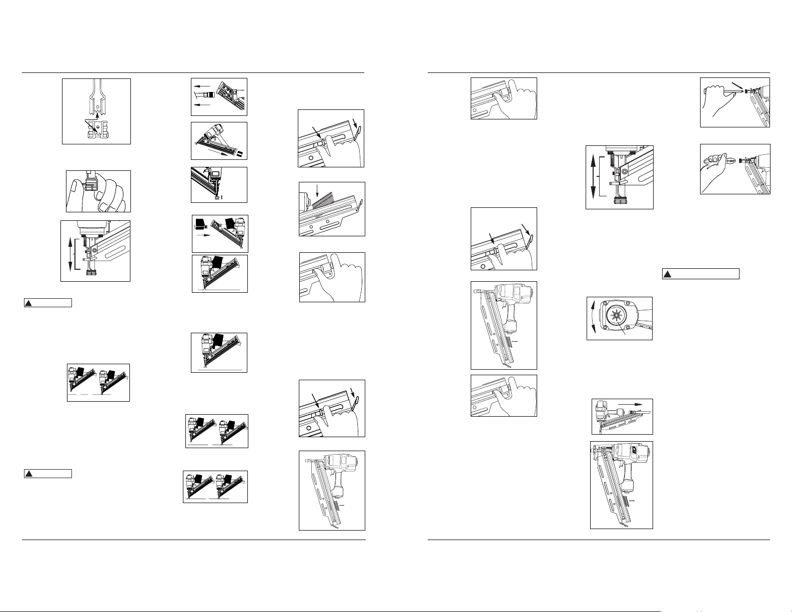
LOADING THE NAILER
1. Always connect the tool to the air
supply before loading fasteners.
2. Pull nail
pusher
mechanism
back until
pusher
engages
with
magazine
latch.
3. Load strips
of fasteners
into the
magazine
slot. Make
sure that
the nails
are placed
into tool at the proper orientation.
4. Squeeze the
pusher and
the latch
together to
unlatch
pusher.
Make sure
the head of the last nail is under the
head of the pusher.
UNLOADING THE NAILER
1. Always unload all fasteners before
removing tool from service.
Unloading is the reverse of loading,
except always disconnect the air
hose before unloading.
2. Pull nail
pusher
mechanism
back until
pusher
engages
with
magazine
latch.
3. Hold tool
upright so
nails will
slide
backwards
toward
magazine
slot.
Nail pusher
mechanism
Latch
4. Carefully
place nomar tip
over the
end of
work
contact
element.
Position
tip onto
WCE
making certain serrated gooves on
each piece are in line and fit snugly
together.
5. Position
retaining
ring on nomar tip and
press firmly
in place.
6. Check
that the
WCE and
trigger
move up
and down
freely
without
sticking or
binding.
Operational Modes
Always know the
operational mode
of the nailer before using. Failure to
know the operational mode could result
in death or serious personal injury.
SINGLE CYCLE MODE
This method is recommended for precise
nail placement. This mode requires the
trigger to be pulled each time a nail is
driven. The
nailer can be
actuated by
depressing the
WCE against the
work surface
followed by pulling the trigger. Or the
nailer can be actuated by pulling the
trigger and then depressing the WCE
against the work surface.
The trigger must be released to reset
the tool before another nail can be
driven.
WORK CONTACT ELEMENT (WCE)
Check the opera-
tion of the Work
Contact Element (WCE) trip mechanism
before each use. The WCE must move
freely without binding through its entire
travel distance. The WCE spring must
return the WCE to its fully extended
position after being depressed. Do not
operate the nailer if the WCE trip
mechanism is not operating properly.
Personal injury may occur.
1. Disconnect the
air supply from
the nailer.
2. Remove all
nails from the
magazine (see
Loading/
Unloading).
3.
Make sure the
trigger and
work contact
element (WCE)
move freely up
and down without sticking or binding.
4. Reconnect air
supply to the
nailer.
5. Depress the
Work Contact
Element (WCE)
against the
work surface
without pulling
the trigger. The nailer MUST NOT
OPERATE. Do not use the tool if it
operates without pulling the
trigger. Personal injury may result.
6. Remove the
nailer from the
work surface.
The Work
Contact
Element (WCE)
must return to its original down
position. The nailer MUST NOT
OPERATE. Do not use the tool if it
operates while lifted from the work
surface. Personal injury may result.
7. Pull the
trigger and
depress the
work contact
element
(WCE) against the work surface. The
nailer MUST NOT OPERATE.
8. Depress the
Work
Contact
Element
(WCE)
against the work surface. Pull the
trigger. The nailer MUST OPERATE.
Operating Instructions
4
Grooves
www.chpower.com
Movement
Nail pusher
mechanism
Latch
El mecanismo
del
empujador
de clavos
El
enganche
!
WARNING
!
CAUTION
1
2
1
1
2
2
Rotate
!
ADVERTENCIA

4. Squeeze the pusher and latch
together to
unlatch the
pusher once
all nails have
been
removed.
ADJUSTING THE NAIL PENETRATION
The NS219000, NS289100, NS289500, and
NS349000 nailers are equipped with an
adjustable depth of drive feature. This
allows the user to determine how deep a
fastener will be driven into the work
surface.
1. Adjust the operating pressure to a
pressure which will consistently
drive the fasteners. Do not exceed
the maximum operating pressure of
the nailer of 120 psi.
2. To adjust the depth-of-drive, loosen
the 4mm bolt on the top of nose. To
increase depth, push WCE in toward
nose as much as desired. Re-tighten
bolt. To decrease depth, pull WCE
out as much as desired. Re-tighten
bolt.
3. Make sure that the trigger and work
contact element (WCE) move freely
up and down without binding or
sticking after each adjustment.
ANTI-DRY FIRE
The NS219000 is equipped with an Anti-Dry
Fire feature. This prevents the WCE from
being pushed in when only a few nails
remain. Simply load new nail clip behind
remaining nails to continue shooting.
ADJUSTING THE DIRECTION OF THE
EXHAUST
The NS219000,
NS289100,
NS289500, and
NS349000
nailers are
equipped with an adjustable direction
exhaust deflector. This is intended to
allow the user to change the direction
of the exhaust. Using the 5mm wrench
provided, loosen the deflector screw;
then twist the deflector to any direction
desired and re-tighten the screw.
CLEARING A JAM FROM THE NAILER
1. Disconnect
nailer from
air supply.
2. Remove all nails
from the
magazine (see
Loading/
Unloading).
Failure to do so
will cause the
nails to eject
from the front
of the tool.
3. Insert a
screwdriver
into the
nose of
the tool.
Push up
on the driver blade to free the
jammed nail.
4. Grab the
jammed
nail with
pliers
and
remove.
Technical Support
Please call our Nailer Hotline at 1-800543-6400 with any questions regarding
the operation or repair of this nailer or
for additional copies of this manual.
If calling from Ohio or outside of the
continental United States, please call
1-513-367-1182.
Fastener And Replacement Parts
Use only
genuine Campbell
Hausfeld fasteners (or equivalent see Fastener Interchange
Information). Use only genuine
Campbell Hausfeld replacement
parts. Never substitute parts. Do not
use modified parts or parts which
will not give equivalent performance
to the original equipment. Tool
performance, safety and durability
could be reduced. When ordering
replacement parts or fasteners,
specify by part number.
Nailer Repair
Nailer repairs must be performed by
qualified and experienced service
people ONLY.
Assembly Procedure For Seals
When repairing a nailer, the internal
parts must be cleaned and lubricated.
Parker O-lube or equivalent must be
used on all o-rings. Each o-ring must be
coated with O-lube before assembling.
A small amount of oil must be used on
all moving surfaces and pivots. After
reassembling, a few drops of 30W nondetergent oil, or equivalent, must be
added through the air line before
testing.
!
WARNING
Models NS219000, NS289100, NS289500 & NS349000
5
5.
Presione el
Elemento de
Contacto de
Trabajo contra la
superficie de
trabajo sin
apretar el gatillo. La clavadora NO DEBE
OPERAR. No use la herramienta si opera
sin apretar el gatillo. Se pueden producir
lesiones personales.
6. Remueva la
clavadora de la
superficie de
trabajo. El Elemento
de Contacto de
Trabajo tiene que
volver a su posición original. La
clavadora NO DEBE OPERAR. No use
la herramienta si opera mientras está
levantada de la superficie de trabajo.
7. Apriete el
gatillo y
presione el
Elemento de
Contacto de
Trabajo contra la superficie de
trabajo. La clavadora NO DEBE
OPERAR.
8. Presione el
Elemento de
Contacto de
Trabajo
contra la
superficie de trabajo. Apriete el
gatillo. La clavadora DEBE OPERAR.
CÓMO CARGAR LA CLAVADORA
1. Siempre conecte la herramienta al
abastecimiento de aire antes de
cargar los sujetadores.
2. Jale el
mecanismo
del
empujador
de clavos
hasta que
éste
engrane
con el
enganche
del cargador.
3. Cargue la
tira de
sujetadores
en la
ranura del
cargador.
Asegúrese
de que los
clavos estén
colocados en la herramienta en la
orientación correcta.
El mecanismo
del
empujador
de clavos
El
enganche
Manual de Instrucciones
4-Sp
5. Cambie la
argolla
retenedora en la
punta no
desgastable,
luego almacene la punta en un lugar
seguro para utilizarla más adelante.
CÓMO INSTALAR LA PUNTA NO
DESGASTABLE
1. Desconecte el
abastecimiento
de aire de la
clavadora.
2. Retire todos los sujetadores del
cargador (ver CÓMO DESCARGAR LA
CLAVADORA).
3. Retire la
argolla que
sujeta a la
punta no
desgastable.
4. Coloque
cuidadosamente la
punta no desgastable sobre
el extremo del
elemento de
contacto de
trabajo (WCE).
Coloque la
punta no
desgastable sobre el elemento de
contacto de trabajo (WCE) haciendo
que algunas ranuras dentadas en
cada pieza estén alineadas y se
ajusten con precisión.
5. Coloque la
argolla
retenedora
sobre la
punta no
desgastable, y
presione firmemente.
6. Verifique
que el
elemento
de
contacto
de trabajo
(WCE) y el
gatillo se
muevan
fácilmente
hacia arriba y hacia abajo sin pegarse
o atracarse.
Modos de Operación
Siempre
cerciórese
de saber en que modo va a operar la
clavadora antes de comenzar a usarla.
De lo contrario, le podría ocasionar la
muerte o heridas graves.
CICLO SENCILLO
Este método se
recomienda para
la colocación
exacta del clavo.
Le debe instalar a
la clavadora el pasador para ciclo sencillo.
Este sistema requiere que oprima el
gatillo cada vez que vaya a clavar un
clavo. Para clavar el elemento de contacto
debe tocar la superficie de trabajo y el
operador debe oprimir el gatillo.
Igualmente, puede oprimir el gatillo
primero y después hacer el contacto.
Debe soltar el gatillo antes de clavar
otro clavo.
ELEMENTO DE CONTACTO
Chequée
el
funcionamiento del mecanismo del
elemento de contacto antes de cada
uso.
El elemento de contacto se debe
desplazar libremente, sin pegarse, a lo
largo del área de desplazamiento. El
resorte del elemento de contacto debe
regresar el elemento de contacto a su
posición original totalmente extendido.
No use la clavadora si el mecanismo del
elemento de contacto no está
funcionando adecudamente. Podría
ocasionarle heridas.
1. Desconecte la
clavadora de la
fuente de
suministro de
aire.
2. Saque todos los
clavos del
cargador (Vea la
Sección CargaDescarga).
3. Cerciórese de
que el gatillo y el
elemento de
contacto se
muevan
libremente en ambos sentidos sin
atascarse o pegarse.
4.
Reconecte la
clavadora a la
fuente de
suministro de aire.
!
Las
ranuras
Movimiento
www.chpower.com
ADVERTENCIA
!
PRECAUCION
1
2
1
1
2
2
Rotate

Operating Instructions
Ésto le
indica
una información importante, que de no
seguirla, le podría ocasionar daños al
equipo.
Evite usar la clavadora cuando el
depósito está vacío. Ésto podría
acelerar su desgasto.
Limpie y chequée todas las
mangueras de suministro de aire y
conexiones antes de conectar la
clavadora al compresor. Reemplace
las mangueras y conexiones que
estén dañadas o desgastadas. El
rendimiento de la herramienta o su
durabilidad podrían reducirse.
Los compresores de aire usados para
suministrarle aire a la clavadora deben
cumplir los requerimientos establecidos
por la organización norteamericana
ANSI en el código B19.3-1981; sobre
seguridad y estándards para
compresores de aire industriales.
Contacte al fabricante de su compresor
de aire para mayor información.
Cómo usar la clavadora
Lea este manual y comprenda todas las
medidas de seguridad e instrucciones
antes de utilizar la clavadora.
LUBRICACION
Esta clavadora requiere lubricación
antes de usarse por primera vez y antes
de cada uso. Si utiliza un lubricador
incorporado a la línea, no tendrá que
lubricarla manualmente a diario.
La super
ficie de
trabajo se podría dañar debido a la
lubricación excesiva. La lubricación
adecuada es la responsabilidad del
propietario. Si no lubrica la clavadora
adecuadamente, ésta se dañará
rápidamente y la garantía se cancelaría.
1. Desconecte la
clavadora de la
fuente de
suministro de
aire para
lubricarla.
2. Gire la clavadora de modo que la
entrada de aire quede mirando hacia
arriba. Agregue de 4 a 5 gotas de
AVISO
aceite no
detergente 30W
en la entrada de
aire. No use
aceites
detergentes,
aditivos de aceite,
ni aceites para
herramientas
neumáticas. Los aceites para
herramientas neumáticas contienen
solventes que pueden averiar los
componentes internos de la
clavadora.
3. Después de agregar
aceite, haga
funcionar la
clavadora
brevemente. Limpie
todo exceso de aceite que salga del
escape de la tapa.
CONEXION RECOMENDADA
1.
El compresor de
aire debe tener
la capacidad de
suministrar un
mínimo de 4,83
bar cuando la
clavadora esté en uso. Si el suministro
de aire es inadecuado podría haber
pérdida de potencia y falta de
consistencia en el funcionamiento.
2. Puede utilizar un
lubricador para
lubricar la
clavadora.
Igualmente, puede
utilizar un filtro
para remover las impurezas líquidas y
sólidas que podrían oxidar u obstruir
las partes internas de la clavadora.
3. Use mangueras
de aire de 9,5
mm diseñadas
para presiones
mínimas de
trabajo de 10,34 bar. Use mangueras
de aire de 12,7 mm si la longitud de
las mismas es de 50’ ó más. Para un
mejor rendimiento, instalele a la
clavadora un conector rápido de 9,5
mm (con roscas de 6,4 mm NPT) cuyo
Modelos NS219000, NS289100, NS289500 y NS349000
3-Sp
4,83 bar
Min.
8,27 bar
Max.
diámetro interno sea de 0,315"
(8mm) y un acoplador rápido de 9,5
mm a la manguera de aire.
4. Use un regulador de presión (de 08,62 bar) en el compresor. Se necesita
un regulador de presión para
controlar la presión de operación de
la clavadora entre 4,83 y 8,27 bar.
PUNTA DE CARGA Y DESCARGA NO
DESGASTABLE
La punta de carga y descarga no
desgastable ha sido diseñada para
eliminar el deterioro causado por el
elemento de contacto de trabajo (WEC)
de dentado. La punta no desgastable
puede retirarse si no se requiere (ver
CÓMO RETIRAR LA PUNTA NO
DESGASTABLE). Utilice la herramienta en
modo de ciclo único (ver MODOS DE
OPERACIÓN) cuando la punta no
desgastable esté en funcionamiento.
CÓMO RETIRAR LA PUNTA NO
DESGASTABLE
1. Desconecte el
abastecimiento
de aire de la
clavadora.
2. Retire todos los sujetadores del
cargador (ver CÓMO DESCARGAR LA
CLAVADORA).
3. Retire la argolla que retiene la punta
no desgastable.
4. Palanquee la
punta no
desgastable
para retirarla
del elemento
de contacto
de trabajo.
Retire la
argolla
La punta no
desgastable
El elemento de
contacto de
trabajo
La
punta no
desgastable
Aceite
Air leaking at trigger valve
Air leaking between
housing and nose
Air leaking between
housing and cap
Nailer skips driving nail
Nailer runs slow or has loss
of power
Nails are jammed in nailer
O-Rings in trigger valve housing are
damaged
Loose screws in housing
Damaged O-Rings
Damage to bumper
Loose screws
Damaged gasket
Worn bumper
Dirt in nose piece
Dirt or damage prevent nails or pusher
from moving freely in magazine
Damaged pusher spring
Inadequate air flow to nailer
Worn O-Ring on piston or lack of
lubrication
Damaged O-Ring on trigger valve
Air leaks
Cap gasket leaking
Nailer not lubricated sufficiently
Broken spring in cylinder cap
Exhaust port in cap is blocked
Guide on driver is worn
Nails are not correct size
Nails are bent
Magazine or nose screws are loose
Driver is damaged
Replace O-Rings. Check operation of Work
Contact Element (WCE)
Tighten screws
Replace O-Rings
Replace bumper
Tighten screws
Replace gasket
Replace bumper
Clean drive channel
Clean magazine
Replace spring
Check fitting, hose or compressor
Replace and lubricate O-Rings
Replace O-Rings
Tighten screws and fittings
Replace gasket
Lubricate nailer
Replace spring
Replace damaged internal parts
Replace guide
Use only recommended nails
Replace with undamaged nails
Tighten screws
Replace driver
Troubleshooting Guide
Stop using nailer immediately if any of the following problems occur. Serious
personal injury could result. Any repairs or replacements must be done by a
Qualified Service Person or Authorized Service Center.
!
WARNING
Problem Cause Solution
Conexion Recomendada
Conector
Rapido
Acoplador
rapido
Manguer
a de aire
Conector rapido
(Opcional)
Acoplador
rapido
(Opcional)
Lubricador
Regulador
Filtro
Fasteners
NS219000 Tool will also drive fasteners designed for: Sears 18465, Porter Cable FR350, Hitachi NR83A, and Senco FramePro
702XP, 752XP, Ridgid R350RHA, and DeWalt D51844, D51845.
NS289100 and NS289500 Tool will also drive fasteners designed for: Sears 18420, Atro Helen 90CH, and Bostitch F28WW, N100S,
N865, N805, N16.
NS349000 Tool will also drive fasteners designed for: Porter Cable FC 350A, Hitachi NR83AA2, Senco FramePro 701XP, 751XP ,
Ridgid R350CHA, DeWalt D51822, D51823, and Paslode F-3505.
www.chpower.com
6
OIL
AVISO

Models NS219000, NS289100, NS289500 & NS349000
7
Protéjase la vista y los
oídos. Use anteojos de
seguridad Z87, con
protección lateral y tápese
los oidos adecuadamente. Los patrones
y los usuarios son responsables de que
tanto los opeerarios como otras
personas en los alrededores se protegan
adecuadamente. De lo contrario podrían
sufrir heridas oculares o sordera
permanente shields.
No use una
válvula de
chequeo o
ninguna
conexión que
permita que el
aire permanezca en la clavadora. Se
puede producir la muerte o lesiones
personales graves.
Nunca ponga las
manos ni ninguna
otra parte del
cuerpo en el área
de descarga de la
clavadora. Ésta
puede expulsar un
sujetador y producir la muerte o
lesiones personales graves.
Nunca cargue la
clavadora por la
manguera de aire
ni hale la
manguera para
mover la clavadora
o el compresor de
aire. Mantenga las mangueras
alejadas del calor, aceite y objetos
puntiagudos. Reemplace cualquier
manguera que esté dañada, débil o
desgastada. Ésto podría ocasionar
heridas o daños a la herramienta
2-Sp
Siempre asuma que la clavadora está
cargada. Nunca la use como juguete.
Siempre mantenga a otros a una
distancia segura en caso de que la
clavadora se dispare
accidentalmente. Nunca la apunte
hacia personas. Si la dispara
accidentalmente podría ocasionarle
la muerte o heridas graves.
No clave un clavo
encima de otro. El
clavo podría saltar
y ocasionarle la
muerte o heridas
graves.
No opere la
clavadora ni
permita que
otros la operen
si las etiquetas
de advertencia
están ilegibles.
Éstas se encuentran en el cargador o
el cuerpo de la clavadora.
Nunca deje la clavadora desatendida
o conectada al compresor de aire si
no la va a usar. Si alguien sin
experiencia comienza a usarla podría
ocasionarle heridas graves.
No deje que la herramienta se caiga
ni la tire. Ésto podría dañarla o
convertirla en algo peligroso de usar.
En caso de que la herramienta se
haya caido o la hayan tirado, revísela
con cuidado a ver si está doblada o
rota, si tiene alguna pieza dañada o
tiene fugas de aire. DEJE de trabajar
y repárela antes de usarla o podría
ocasionarle heridas graves.
Ésto le
indica
que hay una situación que PODRIA
ocasionarle heridas no muy graves.
No modifique o altere la clavadora o
ninguna de sus partes. No use la
clavadora si le faltan alguna de las
tapas protectoras o si éstas han sido
modificadas. No use la clavadora
como un martillo. Se pueden
producir lesiones personales o daños
a la herramienta.
Evite trabajar con esta clavadora por
largos periodos. Deje de usar la
clavadora si siente dolor en las
manos o en los brazos.
Siempre revise
que el
Elemento de
Contacto de
Trabajo esté
funcionando
correctamente.
Puede que se
clave un clavo por accidente si el
Elemento de Contacto de Trabajo no
está funcionando correctamente. Se
pueden producir lesiones personales
(vea la sección “Cómo Revisar el
Elemento de Contacto de Trabajo”).
Desconecte la fuente de suministro
de aire y elimine la tensión del
disparador antes de tratar de sacar
cualquier clavo atascado, ya que la
clavadora podría disparar un
clavopor el frente. Ésto podría
ocasionarle heridas.
!
Manual de Instrucciones
www.chpower.com
Notes
NS219000 NS289100 NS289500 NS349000
• REQUIERE
(m3/min con 16 clavos 0,12 0,12 0,12 0,12
por minuto a 6,21 bar)
• ENTRADA DE AIRE 6,4 mm 6,4 mm 6,4 mm 6,4 mm
(1/4”) NPT (1/4”) NPT (1/4”) NPT (1/4”) NPT
• RANGO DE
LONGITUD 5,08 cm (2”) a 5,08 cm (2”) a 5,08 cm (2”) a 5,08 cm (2”) a
DEL CLAVO 8,89 cm (3.5”) 8,89 cm (3.5”) 8,89 cm (3.5”) 8,89 cm (3.5”)
• RANGO DEL 2,9 mm (0.113”) 2,9 mm (0.113”) 2,9 mm (0.113”) 2,9 mm (0.113”)
CUERPO aaaa
DEL CLAVO 3,3 mm (0.131”) 3,3 mm (0.131”) 3,3 mm (0.131”) 3,3 mm (0.131”)
• CAPACIDAD DEL
CARGADOR 60-75 75-105 75-105 75-105
• PESO 3,77 kg 4,05 kg 3,40 kg 3,94 kg
(8 lbs. 5 oz.) (8 lbs. 15 oz.) (7 lbs. 5oz) (8 lbs. 11oz)
• LONGITUD 49,53 cm (19.5”) 55,25 (21.75”) 55,25 (21.75”) 50,17 cm (19.75”)
• ALTURA 38,10 cm (15”) 38,10 cm (15”) 38,10 cm (15”) 38,10 cm (15”)
• PRESIÓN MÁXIMA 8,27 bar (120 psi) 8,27 bar (120 psi) 8,27 bar (120 psi) 8,27 bar (120 psi)
• RANGO DE PRESIÓN 4,83 - 8,27 bar 4,83 - 8,27 bar 4,83 - 8,27 bar 4,83 - 8,27 bar
(70 - 120 psi) (70 - 120 psi) (70 - 120 psi) (70 - 120 psi)
Componentes y especificaciones de la clavadora
Deflector de escape de dirección ajustable
Agujero roscado/balanceador
mecánico (M8 x 1,25)
Área de
carga de
clavos
Cargador
Gatillo de
ciclo único
Etiquetas de
advertencia
Elemento de contacto de
trabajo
Área de descarga de clavos
PRECAUCION
!
ADVERTENCIA

Operating Instructions
8
Informaciones Generales de
Seguridad
Este manual contiene información
sobre seguridad, funcionamiento
y manteimiento.
Lea este manual y cerciórese
de que comprende todas las
medidas de seguridad e
instrucciones antes de usar la
clavadora. Comuníquese con
un representante de Campbell
Hausfeld si tiene alguna pregunta.
PROPOSICIÓN DE CALIFORNIA 65
Cuando corta lija, taladra o
pule materiales como por
ejemplo madera, pintura,
metal, hormigón, cemento, u otro tipo
de mampostería se puede producir
polvo. Con frecuencia este polvo
contiene productos químicos que se
conocen como causantes de cáncer,
defectos congénitos u otros daños
reproductivos. Use equipo de protección.
RESPONSABILIDAD DEL OPERADOR:
Antes de operar la clavadora, lea y
asegúrese que comprende todas las
advertencias de seguridad y las
etiquetas. Siga las instrucciones de
operación descritas en este manual.
RESPONSABILIDAD DEL EMPLEADOR:
Distribuya este manual de instrucciones
a todos los usuarios antes de permitirles
usar la clavadora. Asegúrese que todos
los operadores lean, comprendan y
sigan todas las advertencias de
seguridad, las etiquetas y las
instrucciones descritas en este manual.
Ésto le indica que hay una situación
inmediata que LE OCASIONARIA la
muerte o heridas de gravedad.
No use ningún tipo de
gases inflamables u
oxigeno para operar la
clavadora. Use sólo
aire comprimido
filtrado, lubricado y
regulado.
Si se usa gas comprimido en
vez de aire comprimido, la clavadora
podría explotar y producir la muerte o
lesiones personales graves.
No exceda la presión
máxima de trabajo de
la clavadora (8,27 bar)
ya que ésta no
funcionará
adecuadamente. No
use una fuente de aire comprimido que
pueda suministrar más de 13,79 bar. La
clavadora podría explotar y producir la
muerte o lesiones personales graves.
Nunca limpie la
clavadora con gasolina
o ningún otro líquido
inflamable. Nunca use
la clavadora en la
cercanías de líquidos o gases
inflamables. Una chispa podría
encender los vapores y ocasionar una
explosión que podría ocasionarle la
muerte o heridas graves.
Siempre colóquese
en una posición
firme y
balanceada para
usar o manipular
la clavadora.
No modifique ni
deshabilite el
Elemento de
Contacto de
Trabajo. No amarre
ni pegue con cinta
Manual de Instrucciones Modelos NS219000, NS289100, NS289500 y NS349000
adhesiva el Elemento de Contacto de
Trabajo ni el gatillo en una posición
oprimida. Se puede producir la muerte o
lesiones personales graves.
No toque el gatillo a
menos que se estén
clavando clavos.
Nunca haga arrancar
la línea de aire con
una clavadora ni
mueva la clavadora
cuando esté tocando el gatillo. La
herramienta podría expulsar un
sujetador y producir la muerte o
lesiones personales graves.
Ésto le
indica que
hay una situación que PODRIA
ocasionarle la muerte o heridas graves.
Siempre
desconecte la
clavadora de la
tubería de aire
antes de despejar
atascamientos, ajustar o dar servicio a
la clavadora, cuando se vuelva a cargar,
o cuando no se está usando. Siempre
vuelva a conectar la tubería de aire
ANTES de cargar los sujetadores. La
clavadora puede expulsar un sujetador
y producir la muerte o lesiones
personales graves.
Sírvase leer y guardar estas instrucciones.Lea con cuidado antes de tratar de armar, instalar, manejar o darle servicio al producto descrito en
este manual. Protéjase Ud. y a los demás observando todas las reglas de seguridad. El no seguir las instrucciones podría resultar en heridas y/o
daños a su propiedad. Guarde este manual como referencia.
IN703802AV 2/07
Las clavadoras de Campbell Hausfeld Nailers cumplen o exceden los estándards de la Industria
establecidos en los códigos SNT-101-2002 de las organizaciones norteamericanas ANSI/ISANTA .
© 2007 Campbell Hausfeld.
Índice
Info. Generales de Seguridad . . . .1-2
Especificaciones . . . . . . . . . . . . . . . .2
Funcionamiento de la clavadora . . .3
Modos de funcionamiento . . . . . . .4
Clavos . . . . . . . . . . . . . . . . . . . . . . . .6
Diagnóstico de averías . . . . . . . . . . .7
Garantía . . . . . . . . . . . . . . . . . . . . . .8
8,27 bar
Max.
Descripción
La clavadora ha sido diseñada para
marcos, armaduras, subsuelos,
encofrados, plataformas exteriores y
ensamblaje de construcción de tarimas.
Las características incluyen: cargador de
conveniente capacidad terminal, punta
no desgastable, escape ajustable, gatillo
de ciclo único y un mecanismo ajustable
de profundidad de accionamiento.
www.chpower.com
Localice el número del modelo y el
código de
fecha
en la herramienta, el depósito y la tapa, y
regístrelos a continuación:
Modelo No ______________________
código de fecha
___________________
Conserve estos números
para referencia.
Limited Warranty
1. DURATION: From the date of purchase by the original purchaser as follows: Standard Duty Products - One
Year, Serious Duty Products - Two Years, Extreme Duty Products - Three Years.
2. WHO GIVES THIS WARRANTY (WARRANTOR): Campbell Hausfeld / Scott Fetzer Company, 100 Production
Drive, Harrison, Ohio, 45030, Telephone: (800) 543-6400
3. WHO RECEIVES THIS WARRANTY (PURCHASER): The original purchaser (other than for purposes of resale)
of the Campbell Hausfeld product.
4. WHAT PRODUCTS ARE COVERED BY THIS WARRANTY: Any Campbell Hausfeld nailer, stapler, air tool, spray
gun, inflator or air accessory supplied or manufactured by Warrantor.
5. WHAT IS COVERED UNDER THIS WARRANTY: Substantial defects in material and workmanship which occur
within the duration of the warranty period.
6. WHAT IS NOT COVERED UNDER THIS WARRANTY:
A. Implied warranties, including those of merchantability and FITNESS FOR A PARTICULAR PURPOSE ARE
LIMITED FROM THE DATE OF ORIGINAL PURCHASE AS STATED IN THE DURATION. If this product is used
for commercial, industrial or rental purposes, the warranty will apply for ninety (90) days from the date
of purchase. Some States do not allow limitation on how long an implied warranty lasts, so the above
limitations may not apply to you.
B. ANY INCIDENTAL, INDIRECT, OR CONSEQUENTIAL LOSS, DAMAGE, OR EXPENSE THAT MAY RESULT
FROM ANY DEFECT, FAILURE, OR MALFUNCTION OF THE CAMPBELL HAUSFELD PRODUCT. Some States
do not allow the exclusion or limitation of incidental or consequential damages, so the above limitation
or exclusion may not apply to you.
C. Any failure that results from an accident, purchaser’s abuse, neglect or failure to operate products in
accordance with instructions provided in the owner’s manual(s) supplied with product. Accident,
purchaser’s abuse, neglect or failure to operate products in accordance with instructions shall also
include the removal or alteration of any safety devices. If such safety devices are removed or altered,
this warranty is void.
D. Normal adjustments which are explained in the owner’s manual(s) provided with the product.
E. Items or service that are normally required to maintain the product, i.e. o-rings, springs, bumpers,
debris shields, driver blades, fuses, batteries, gaskets, packings or seals, fluid nozzles, needles, sandblast
nozzles, lubricants,
material hoses, filter elements, motor vanes, abrasives, blades, cut-off wheels,
chisels
, chisel retainers, cutters, collets, chucks, rivet jaws, screw driver bits, sanding pads, back-up pads,
impact mechanism, or any other expendable part not specifically listed. These items will only be
covered for ninety (90) days from date of original purchase. Underlined items are warranted for defects
in material and workmanship only.
7. RESPONSIBILITIES OF WARRANTOR UNDER THIS WARRANTY: Repair or replace, at Warrantor’s option,
products or components which are defective, have malfunctioned and/or failed to conform within duration
of the warranty period.
8. RESPONSIBILITIES OF PURCHASER UNDER THIS WARRANTY:
A. Provide dated proof of purchase and maintenance records.
B. Deliver or ship the Campbell Hausfeld product or component to the nearest Campbell Hausfeld
Authorized Service Center. Freight costs, if any, must be borne by the purchaser.
C. Use reasonable care in the operation and maintenance of the products as described in the owner’s
manual(s).
9. WHEN WARRANTOR WILL PERFORM REPAIR OR REPLACEMENT UNDER THIS WARRANTY: Repair or
replacement will be scheduled and serviced according to the normal work flow at the servicing location,
and depending on the availability of replacement parts.
This Limited Warranty applies in the United States, Canada and Mexico only and gives you specific legal rights.
You may also have other rights which vary from state to state or country to country.
Clavador de
Armazones
BUILT TO LAST
!
PELIGRO
!
PELIGRO
MANUAL
O
CO
2
!
ADVERTENCIA

RESPONSABILITÉ DE L’EMPLOYEUR
Ce manuel d’instruction doit être mis à
la disposition de tous les utilisateurs
avant qu’ils ne se servent de la cloueuse.
S’assurer que tous les utilisateurs lisent
et comprennent parfaitement les
notices de sécurité, étiquettes et
instructions décrites dans ce manuel.
Danger
indique
une situation hasardeuse imminente
qui RÉSULTERA en perte de vie ou
blessures graves.
Ne pas utiliser un gaz
inflammable ni
l’oxygène pour
alimenter la cloueuse.
Utilisez seulement de
l’air comprimé filtré,
lubrifié et réglé.
L’utilisation d’un gaz comprimé au
lieu de l’air comprimé peut faire
exploser la cloueuse et entraîner des
blessures graves ou mortelles.
Ne pas dépasser la
pression de service
maximale de la
cloueuse (827 kPa).
La cloueuse ne
fonctionnera pas
correctement. Ne pas
utiliser une source
d’air comprimé qui a une capacité de
plus que 1379 kPa. La cloueuse
pourrait exploser et causer des
blessures graves ou mortelles.
Ne jamais utiliser de
l’essence ni les fluides
inflammables pour le
nettoyage de la
cloueuse. Ne jamais
utiliser la cloueuse
près d’un liquide ou gaz inflammable.
Une étincelle peut allumer les vapeurs
et causer une explosion qui peut
résulter en perte de vie ou blessures
graves personnelles.
Toujours bien
s’équilibrer
pendant la
manipulation ou
l’utilisation de la
cloueuse.
Généralités Sur La Sécurité
Ce manuel contient des informations
concernant la sécurité, le
fonctionnement et l’entretien.
Lire attentivement ce manuel
et comprendre tous les
avertissements de sécurité et
les instructions avant
d’utiliser la cloueuse. Si vous
avez des questions, contacter un
représentant de Campbell Hausfeld.
PROPOSITION 65 CALIFORNIE
Vous pouvez créer de la
poussière en coupant,
ponçant, perçant ou meulant
les matériaux tels que le bois, la
peinture, le métal, le béton, le ciment
ou autre maçonnerie. Cette poussière
contient souvent des produits
chimiques reconnus pour causer le
cancer, les déformations congénitales
ou autres problèmes de la reproduction.
Portez de l’équipement de protection.
RESPONSABILITÉ DE L’UTILISATEUR
Avant d’utiliser cette cloueuse, prendre
connaissance de tous les avertissements
et des étiquettes concernant la sécurité.
Suivre les instructions données dans ce
manuel.
Instructions D’Utilisation Modèles NS219000, NS289100, NS289500 et NS349000
Ne jamais
modifier ou
empêcher le
fonctionnement
du mécanisme
de
déclenchement
par contact
(WCE) et ne
jamais maintenir la gâchette
enfoncée à l’aide de ruban adhésif
par exemple. Ceci pourrait entraîner
des blessures graves ou mortelles.
Ne toucher à la
gâchette qu’au
moment de poser
des clous. Ne
jamais actionner
la gâchette
durant le
transport de la
cloueuse ou
durant le raccordement de celle-ci
au tuyau d’air comprimé. L’éjection
accidentelle d’un clou peut causer
des blessures graves ou mortelles.
Cloueuse à
Charpente
S’il vous plaît lire et conserver ces instructions. Lire attentivement avant de monter, installer, utiliser ou de procéder à l’entretien du produit
décrit. Se protéger ainsi que les autres en observant toutes les instructions de sécurité, sinon, il y a risque de blessure et/ou dégâts matériels!
Conserver ces instructions comme référence.
IN703802AV 2/07
Les Cloueuses Campbell Hausfeld conforment aux/ou dépassent les standards de l’American
National Standard/International Staple, Nail and Tool Association in ANSI/ISANTA SNT-101-2002. ©
2007 Campbell Hausfeld
Description
Cette cloueuse est conçue pour la
charpenterie, les armatures, les
sousplanchers, le revêtement, les terrasses
extérieures et les montages de palette/
caisse à claire-voie. Les caractéristiques
comprennent un chargeur du haut
pratique, une buse non-gâcheuse,
échappement orientable, gâchette à
cycle unique et un mécanisme de contrôle
de profondeur d’enfoncement.
Instructions D’Utilisation
8-Fr
827 kPa
Max.
Table Des Matières
Directives De Sécurité . . . . . . . .1-2
Spécifications . . . . . . . . . . . . . . . .2
Fonctionnement De La Cloueuse . .3
Modes De Fonctionnement . . . . . .4
Attaches . . . . . . . . . . . . . . . . . . .6
Guide De Dépannage . . . . . . . . . .7
Garantie . . . . . . . . . . . . . . . . . . . .8
Garantie Limitée
1. DURÉE: À partir de la date d’achat par l’acheteur original comme suit - Produits À Service Standard
(Standard Duty) - Un An, Produits À Service Sérieux (Serious Duty) - Deux Ans, Produits À Service Extrême
(Extreme Duty) - Trois Ans.
2. GARANTIE ACCORDÉE PAR (GARANT): Campbell Hausfeld/Scott Fetzer Company, 100 Production Drive,
Harrison, Ohio, 45030, Téléphone: (800) 543-6400
3. BÉNÉFICIAIRE DE CETTE GARANTIE (ACHETEUR): L’acheteur original (sauf en cas de revente) du produit
Campbell Hausfeld.
4. PRODUITS COUVERTS PAR CETTE GARANTIE: Tous les outils de fixation (cloueuses et agrafeuses), outils
pneumatiques, pistolets vaporisateurs, gonfleurs ou accessoires pneumatiques Campbell Hausfeld qui sont
fournis par ou fabriqués par le Garant.
5. COUVERTURE DE LA PRÉSENTE GARANTIE: Défauts de matière et de fabrication considérables qui se
révèlent pendant la période de validité de la garantie.
6. LA PRÉSENTE GARANTIE NE COUVRE PAS:
A. Les garanties implicites, y compris celles de commercialisabilité et D’ADAPTION À UNE FONCTION
PARTICULIÈRE SONT LIMITÉES À PARTIR DE LA DATE D’ACHAT INITIALE TELLE QU’INDIQUÉE DANS LA
SECTION DURÉE. Si ce produit est utilisé pour une fonction commerciale, industrielle ou pour la location,
la durée de la garantie sera quatre-vingt-dix (90) jours à compté de la date d’achat. Quelques Provinces
(États) n’autorisent pas de limitations de durée pour les garanties implicites. Les limitations précédentes
peuvent donc ne pas s’appliquer.
B. TOUT DOMMAGE, PERTE OU DÉPENSE FORTUIT OU INDIRECT POUVANT RÉSULTER DE TOUT DÉFAUT,
PANNE OU MAUVAIS FONCTIONNEMENT DU PRODUIT CAMPBELL HAUSFELD. Quelques Provinces (États)
n’autorisent pas l’exclusion ni la limitation des dommages fortuits ou indirects. La limitation ou
exclusion précédente peut donc ne pas s’appliquer.
C. Toute panne résultant d’un accident, d’une utilisation abusive, de la négligence ou d’une utilisation ne
respectant pas les instructions données dans le(s) manuel(s) accompagnant le produit. Un accident,
l’utilisation abusive par l’acheteur, la négligence ou le manque de faire fonctionner les produits selon
les instructions comprend aussi l’enlevage ou la modification de n’importe quel appareil de sûreté. Si ces
appareils de sûreté sont enlevés ou modifiés, la garantie sera annulée.
D. Réglages normaux qui sont expliqués dans le(s) manuel(s) d’utilisation accompagnant le produit.
E. Articles ou services qui sont exigés pour l’entretien du produit; Joints torique, ressorts, amortisseurs,
écrans de débris, lames d’entraînement,
fusibles, batteries, joints d’étanchéité, garnitures ou joints,
buses de fluide, aiguilles, buses de sablage, graisses, tuyaux de matériaux, cartouches filtrantes, pales de
moteur,
abrasifs, lames, meules de coupage, burins, fixe-burins, coupeuses, douilles de serrage,
mandrins. mâchoires de rivet, lames de tournevis, tampons de sablage, tampons de sauvegarde,
mécanisme de percussion ou toute pièce qui n’est pas indispensable et qui n’est pas indiquée. Ces
articles seront couverts pour quatre-vingt-dix (90) jours à partir de la date d’achat original. Les articles
soulignés sont garanties pour défauts de matière et de fabrication seulement
.
7. RESPONSABILITÉS DU GARANT AUX TERMES DE CETTE GARANTIE: Réparation ou remplacement, au choix
du Garant, des produits ou pièces qui se sont révélés défectueux pendant la durée de validité de la garantie.
8. RESPONSABILITÉS DE L’ACHETEUR AUX TERMES DE CETTE GARANTIE:
A. Fournir une preuve d’achat datée et un état d’entretien.
B. Livraison ou expédition du produit ou de la pièce Campbell Hausfeld au Centre De Service Autorisé
Campbell Hausfeld. Taux de frais, si applicables, sont la responsabilité de l’acheteur.
C. Utilisation et entretien du produit avec un soin raisonable, ainsi que le décri(vent)t le(s) manuel(s)
d’utilisation.
9. RÉPARATION OU REMPLACEMENT EFFECTUÉ PAR LE GARANT AUX TERMES DE LA PRÉSENTE GARANTIE: La
réparation ou le remplacement sera prévu et exécuté en fonction de la charge de travail dans le centre de
service et dépendra de la disponabilité des pièces de rechange.
Cette Garantie Limitée s’applique aux É.-U., au Canada et au Mexique seulement et vous donne des droits
juridiques précis. L’acheteur peut également jouir d’autres droits qui varient d’une Province, d’un État ou d’un
Pays à l’autre.
Trouver le modèle et le code de date sur
le chargeur et le capuchon de l’outil et
les inscrire plus bas.
N° de modèle ____________________
Code de date
______________________
Conserver ces numéros
comme référence.
BUILT TO LAST
!
DANGER
!
DANGER
MANUAL
O
CO
2

Avertissment indique une situation
hasardeuse potentielle qui PEUT résulter
en perte de vie ou blessures graves.
Toujours
débrancher le
tuyau d’air
comprimé de la
cloueuse avant de
dégager un clou
bloqué, de régler,
de réparer ou de transporter la cloueuse
ou lorsque celle-ci n’est pas en service. Le
raccordement du tuyau d’air comprimé
doit toujours s’effectuer AVANT le
chargement du magasin. L’éjection
accidentelle d’un clou peut causer des
blessures graves ou mortelles.
Protéger vos yeux avec
des lunettes de sécurité
Z87 à écrans latéraux et
vos oreilles avec un
protecteur auditif. Le
patron et l’utilisateur
sont responsables pour assurer que
l’utilisateur et ceux à proximité de la
cloueuse portent l’équipement de
securite, sinon, il y a risque de blessures
graves oculaires ou de dommage
permanent a l’ouie. sécurité, sinon, il y
a risque de blessures graves oculaires
l’équipement de sécurité, sinon, il y a
risque de blessures graves oculaires ou
de dommage permanent à l’ouie.
sécurité, sinon, il y a risque de blessures
graves oculaires ou de dommage
permanent à l’ouïe.
Ne pas utiliser
un clapet ni
autre raccord qui
permet que l’air
reste dans la
cloueuse.
Cela
peut entraîner
des blessures graves ou mortelles.
!
2-Fr
Ne jamais poser
l’embout de
clouage sur la
main ou sur toute
autre partie du
corps. L’éjection
accidentelle d’un
clou peut causer des blessures
graves ou mortelles.
Ne jamais
transporter la
cloueuse par le
tuyau à air. Ne
jamais tirer sur le
tuyau pour
déplacer la
cloueuse ou le compresseur. Garder
le tuyau à air à l’écart de la chaleur,
l’huile et les objets pointus.
Remplacer les tuyaux endommagés,
faibles ou usés. Sinon, il y a risque
de blessures personnelles ou de
dommage à l’outil.
Toujours présumer que la cloueuse
contient des clous. Ne jamais traiter
la cloueuse de jouet. Toujours tenir
les autres personnes à l’écart de
l’endroit de travaille en cas
d’expulsion accidentelle. Ne jamais
diriger la cloueuse vers une autre
personne. Le déclenchement
accidentel de la cloueuse peut
causer la mort ou blessures graves.
Ne jamais enfoncer
les clous un par
dessus l’autre. Le
clou pourrait
ricocher et causer
la mort ou une
blessure grave de
perforation.
Ne pas utiliser
la cloueuse/ni
permettre
qu’une autre
personne
l’utilise si les
avertissements
ou les étiquettes d’avertissement
situés sur le chargeur et corps de la
cloueuse ne sont pas lisables.
Ne jamais laisser la cloueuse sans
surveillance ni branchée à un
compresseur si hors-service. Il y a
risque de blessures graves si la
cloueuse est utilisée par une
personne qui ne connait pas les
instructions d’utilisation.
Ne pas échapper ni jeter l’outil car ceci
peut causer du dommage le rendant
dangereux à utiliser. Si l’outil s’est fait
échappé ou jeté, l’examiner
soigneusement afin de déterminer s’il
est courbé, fendu ou s’il y a des fuites
ou pièces détachées endommagées.
ARRËTER et réparer avant d’uitliser ,
sinon, il y a risque de blessures graves.
Attention
indique
une situation hasardeuse potentielle
qui PEUT résulter en blessures.
Ne pas modifier ni altérer la
cloueuse ou ces pièces. N’utilisez pas
une cloueuse si les écrans ou
protecteurs ont été enlevés ou
altérés. Cela peut entraîner des
blessures ou endommager l’appareil.
Éviter d’utiliser la cloueuse pour une
période de temps prolongée. Cesser
d’utiliser la cloueuse si l’on ressent
des douleurs dans les mains ou dans
les bras.
Toujours vérifier
le bon
fonctionnement
du mécanisme de
déclenchement
par contact
(WCE). L’éjection
accidentelle de
clou peut se
produire si ce mécanisme ne
fonctionne pas correctement et cela
pourrait entraîner des blessures. (Voir
“Vérification du mécanisme de
déclenchement par contact”).
Instructions D’Utilisation
Modèles NS219000, NS289100, NS289500 et NS349000
7-Fr
NS219000 NS289100 NS289500 NS349000
• REQUIERT
(mΔ/min avec 16 clous 0,12 0,12 0,12 0,12
par minute @ 621 kPa)
• ARRIVÉE D’AIR 1/4 po NPT 1/4 po NPT 1/4 po NPT 1/4 po NPT
• GAMME DE LONGUEUR
DE CLOUS 2 po - 3
1
⁄
2 po 2 po - 3
1
⁄
2 po 2 po - 3
1
⁄
2 po 2 po - 3
1
⁄
2 po
• GAMME DE TIGES 0.113 po - 0.113 po - 0.113 po - 0.113 po -
DE CLOUS 0.131 po 0.131 po 0.131 po 0.131 po
• CAPACITÉ DU
CHARGEUR 60-75 75-105 75-105 75-105
• POIDS 3,77 kg 4,05 kg 3,40 kg 3,94 kg
• LONGUEUR 49,53 cm 55,25 cm 55,25 cm 50,17 cm
• HAUTEUR 38,10 cm 38,10 cm 38,10 cm 38,10 cm
• PRESSION MAXIMUM 827 kPa 827 kPa 827 kPa 827 kPa
• GAMME DE PRESSION 483-827 kPa 483-827 kPa 483-827 kPa 483-827 kPa
Pièces Détachées Et Spécifications De La Cloueuse
Déflecteur de direction
d’échappement réglable
Trou fileté/Balancier
d’outil (M8 x 1.25)
Endroit de
chargement
de clous
Chargeur
Gâchette de
cycle unique
Décalcomanies
de sécurité
Mécanisme de
déclenchement par contact
Endroit d’expulsion de clous
Fuite d’air à l’endroit de la
soupape de la gâchette
Fuite d’air entre le carter et le nez
Fuite d’air entre le carter et le
capuchon
La cloueuse saute un clou
pendant l’expulsion
La cloueuse fonctionne
lentement ou a une perte de
puissance
Blocage des clous
Joints torique endommagés dans le carter
de la soupape de la gâchette
Vis desserrées dans le carter
Joints torique endommagés
Amortisseur endommagé
Vis desserrées
Joint d’étanchéité endommagé
Amortisseur usé
Saleté dans la pièce du nez
Saleté ou dommage qui empêche le
fonctionnement libre des clous ou du
poussoir dans le chargeur
Ressort de poussoir endommagé
Circulation d’air insuffisante à la cloueuse
Joint torique du piston usé ou manque de
lubrification
Joint torique de la soupape de gâchette
endommagé
Fuites d’air
Fuite du joint étanchéité du capuchon
Graissage insuffisant de la cloueuse
Rupture du ressort du capuchon de cylindre
Orifice d’échappement du capuchon obstrué
Guide du chassoir usé
Clous de mauvaise taille
Clous courbés
Vis du chargeur ou nez dégagés
Chassoir endommagé
Remplacer les joints toriques et vérifier lefonctionnement
du mécanisme de déclenchement par contact
Serrer les vis
Remplacer les joints torique
Remplacer l’amortisseur
Serrer les vis
Remplacer le joint d’étanchéité
Remplacer l’amortisseur
Nettoyer la rainure du chassoir
Nettoyer le chargeur
Remplacer le ressort
Inspecter le raccord, tuyau ou le compresseur
Remplacer les joints torique. Graisser.
Remplacer les joints torique
Serrer les vis et raccords
Remplacer le joint d’étanchéité
Graisser la cloueuse
Remplacer le ressort
Remplacer les pièces internes endommagées
Remplacer le guide
Utiliser les clous de taille recommandée
Remplacer les clous
Serrer les vis
Remplacer le chassoir
Guide De Dépannage
Cessez l’utilisation de la cloueuse immédiatement en cas des problèmes suivants, car il
résultat risque de blessures graves. Toutes réparations doivent être effectuées par un
Technicien Qualifié ou par un Centre De Service Autorisé.
Problème Cause Solution
AVERTISSEMENT
!
AVERTISSEMENT
!
ATTENTION
!
AVERTISSEMENT

Pour éviter l’expulsion d’une attache,
débrancher la source d’air et relâcher
la tension du poussoir avant de
procéder au déblocage. Sinon, il y a
risque de blessures graves.
Avis
indique
de l’information importante pour éviter
le dommage de l’équipement.
Éviter d’utiliser la cloueuse lorsque
le chargeur est vide. Sinon, il y a
risque d’usure accéléré de l’outil.
Nettoyer et vérifier tous les tuyaux
et raccords avant de brancher la
cloueuse au compresseur d’air.
Remplacer les tuyaux ou les raccords
endommagés ou usés, sinon, le
rendement et la durabilité de l’outil
seront affectés.
Le compresseur d’air utilisé avec
cette cloueuse doit conformer aux
exigences établies par l’American
National Standards Institute
Standard B19.3-1981; Safety
Standard for Compressors for
Process Industries. Contacter le
fabricant du compresseur pour plus
d’informations.
Utilisation de la Cloueuse
Lire attentivement ce manuel afin de
comprendre tous les avertissements de
sécurité et instructions avant d’utiliser la
cloueuse.
GRAISSAGE
Cette cloueuse exige le graissage avant
son usage initial et avant chaque usage.
Si vous utilisez un graisseur en
canalisation, le graissage manuel à
travers la prise d’air n’est pas exigé
quotidiennement.
La sur
face de
travail peut être endommagée par le
graissage excessif. Le graissage
correct est la responsabilité de
l’utilisateur. Manque de graisser la
cloueuse correctement peut raccourcir
la durée de la cloueuse et peut
annuler votre garantie.
1. Débrancher la
source d’air de la
cloueuse avant
de graisser.
Modèles NS219000, NS289100, NS289500 et NS349000
2. Tourner la
cloueuse de
manière à ce
que la prise
d’air comprimé
soit dirigée vers
le haut.
Introduire 4 ou
5 gouttes d’huile non-détergente
dans la prise d’air comprimé. Ne pas
utiliser d’huile détergente, d’additif
à huile ni d’huile pour outils à air
comprimé. Ces dernières
contiennent des solvants qui
peuvent endommager les pièces
intérieures de la cloueuse.
3. Après
l’addition
d’huile, faire
fonctionner
brièvement
la cloueuse.
Enlever tout excès d’huile sortant
par le déflecteur d’échappement.
BRANCHEMENT RECOMMANDÉ
1. Le compresseur
d’air doit
conserver un
minimum de
483 kPa
pendant
l’utilisation de
la cloueuse. L’alimentation d’air
insuffisante peut réduire la
puissance de la cloueuse et peut
affecter l’efficacité de
l’enfoncement.
2. Un graisseur
peut être
utilisé pour
fournir la
circulation
d’huile à travers la cloueuse. Un
filtre peut être utilisé pour enlever
les matières liquides et solides qui
peuvent encrasser les pièces
internes de la cloueuse.
3. Utiliser des
tuyaux d’air
de 9,5 mm
avec une
pression de
service minimum de 1034 kPa. Utiliser
3-Fr
483 kPa
Min.
827 kPa
Max.
Instructions D’Utilisation
6-Fr
les tuyaux d’air de 12,7 mm pour 15 m
ou plus. Pour un meilleur rendement,
installer un bouchon rapide de 9,5mm
avec (filets d’1/4 po NPT) un diamètre
intérieur de ,315 po (8mm) sur la
cloueuse et un raccord rapide de 9,5
mm sur le tuyau.
4. Utiliser un régulateur de pression
sur le compresseur avec une pression
de service de 0 - 862 kPa. Un
régulateur de pression est
indispensable pour maintenir la
pression de service de la cloueuse
entre 483 et 827 kPa.
BUSE NON-GÂCHEUSE POUR
TERRASSES
La buse non-gâcheuse pour terrasses est
conçue pour éliminer les marques
causées par le mécanisme de
déclenchement par contact (WCE)
dentelé. Vous pouvez enlever la buse
non-gâcheuse au besoin (Voir la section
ENLEVER LA BUSE NON-GÂCHEUSE
POUR TERRASSES). Utiliser l’outil dans le
mode cycle unique (VOIR LES MODES
DE FONCTIONNEMENT) lorsque la buse
non-gâcheuse soit en place.
ENLEVER LA BUSE NON-GÂCHEUSE
POUR TERRASSES
1. Débrancher la
source d’air de la
cloueuse.
2. Enlever toutes les attaches du
chargeur (Voir DÉCHARGER LA
CLOUEUSE).
3. Enlever la bague de retenue de la
buse non-gâcheuse.
Bague
De
Retenue
Buse Non-Gâcheuse
Attaches
L’outil NS219000 peut utiliser les attaches conçues pour: Sears 18465, Porter Cable FR350, Hitachi NR83A, and Senco FramePro
702XP, 752XP, Ridgid R350RHA, and DeWalt D51844, D51845.
L’outil NS289100 et NS289500 peut utiliser les attaches conçues pour: Sears 18420, Atro Helen 90CH, and Bostitch F28WW, N100S, N865,
N805, N16.
L’outil NS349000 peut utiliser les attaches conçues pour: Porter Cable FC 350A, Hitachi NR83AA2, Senco FramePro 701XP, 751XP
, Ridgid R350CHA, DeWalt D51822, D51823, and Paslode F-3505.
OIL
Branchement Recommandé
Bouchon
Rapide
Raccord
Rapide
Tuyau À
Air
Bouchon
Rapide
(Optionnel)
Raccord
Rapide
(Optionnel)
Graisseur
Régulateur
Filtre
D’huile
Attaches et Réparation
de la Cloueuse
Les réparations doivent être effectuées
par des techniciens qualifiés SEULEMENT.
Méthode d’assemblage pour les
joints d’étanchéité
Les pièces internes doivent être ne
toyées et graissées pendant la
réparaton d’une cloueuse. Utiliser le
Parker O-lube ou l’équivalent sur tous
les joints toriques. Chaque joint
torique doit être enrobé avec du Olube avant l’assemblage. Utiliser un
peu d’huile sur tous les surfaces
mouvantes et pivots. Après le
remontage, ajouter quelque gouttes
d’huile sans détergent 30W ou
l’équivalent à travers la canalisation
d’air avant de faire l’essai.
Notes
AVIS
AVIS

4. Brancher à
nouveau la
source d’air à
la cloueuse.
5. Appuyer le
mécanisme de
déclenchement
par contact
(WCE) sur la
surface de
travail sans
actionner la gâchette. La cloueuse
NE DOIT PAS FONCTIONNER. Si
l’éjection d’un clou se produit sans
que l’on actionne la gâchette, ne
pas utiliser cet appareil. Il y a risque
de blessures.
6.
Oter la
cloueuse de la
surface de
travail. Le
mécanisme de
déclenchement
par contact (WCE) doit redescendre à
sa position initiale. La cloueuse NE
DOIT PAS FONCTIONNER. Si
l’éjection d’un clou se produit
lorsqu’on relève la cloueuse, ne pas
utiliser celle-ci. Il y a risque de
blessures.
7. Actionner la
gâchette.
Appuyer le
mécanisme
de
déclenchement par contact (WCE)
sur la surface de travail. La cloueuse
NE DOIT PAS FONCTIONNER
.
8. Appuyer
le
mécanisme
de
déclenchement par contact (WCE)
sur la surface de travail. Actionner
la gâchette. La cloueuse DOIT
FONCTIONNER.
CHARGER LA CLOUEUSE
1. Toujours brancher l’outil à la source
d’air avant de charger les attaches.
2. Tirer sur le
mécanisme
de poussoir
de clous
jusqu’à ce
qu’il se met
en prise
avec le
loquet du
chargeur.
4. Décoller la buse non-gâcheuse du
mécanisme de déclenchement par
contact.
5. Remplacer
la bague de
retenue sur
la buse nongâcheuse et
entreposer
la buse dans un endroit sûr pour
l’usage dans le futur.
INSTALLER LA BUSE NON-GÂCHEUSE
1. Débrancher la
source d’air de la
cloueuse.
2. Enlever toutes les attahces du
chargeur (Voir DÉCHARGER LA
CLOUEUSE).
3. Enlever la bague de
retenue de la buse
non-gâcheuse.
4. Placer la buse
non-gâcheuse
soigneusement
sur le bout du
mécanisme de
déclenchement
par contact.
Positionner la
buse sur le
mécanisme de
déclenchement par contact (WCE) en
s’assurant que les rayures dentelées de
chaque pièce soient alignées et
serrées ensembles.
5. Positionner
la bague de
retenue sur
la buse nongâcheuse et
appuyer
fermement
pour le mettre en place.
6. Vérifier que
le
mécanisme
de
déclenchement par
contact
(WCE) et la
gâchette se déplacent librement sans
collage ou coinçage.
3. Charger les
attaches
dans la
fente du
chargeur.
S’assurer
que les clous soient bien orientés
losqu’ils soient changés dans l’outil.
4. Serrer le
poussoir et
le loquet
ensemble
pour
dégager le
poussoir.
S’assurer que la tête du dernier clou
soit sous la tête du poussoir.
DÉCHARGER LA CLOUEUSE
1. Toujours décharger la cloueuse
lorsqu’elle n’est pas en service.
Décharger est le contraire de charger
sauf qu’il faut toujours débrancher le
tuyau à air avant de décharger.
2. Tirer le
mécanisme
de poussoir
jusqu’à ce
que le
poussoir se
met en prise
avec le
loquet du
chargeur.
3. Tenir l’outil
droit pour
que les
clous
glissent à
l’arrière vers
la vent du
chargeur.
4. Serrer le
poussoir et
le loquet
ensemble
pour
dégager le
poussoir
une fois que tous les clous ont été
enlevés.
RÉGLER LA PÉNÉTRATION DES CLOUS
Les cloueuses NS219000, NS289100,
NS289500 et NS349000 sont équipés d’un
mécanisme pour contrôler la profondeur
d’enfoncement. Ceci permet à l’utilisateur
de déterminer comment profondémment
une attache sera enfonçée dans la surface
de travail.
1. Régler la pression de service à une
pression qui enfonçera les attaches
constamment. Ne pas dépasser la
pression de service maximum de la
cloueuse (827 kPa).
2. Pour ajuster la profondeur
d’enfoncement, desserrer le boulon
de 4 mm sur le dessus de la buse. Pour
augmenter la profondeur, pousser le
WCE (mécanisme de déclenchement
par contact) vers l’intérieur, vers la
buse à la longueur voulue. Resserrer
le boulon. Pour réduire la
profondeur, retirer le WCE à la
longueur voulue. Resserrer le boulon.
3. S’assurer que la gâchette et le
mécanisme de déclenchement par
contact (WCE) se déplacent librement
sans se coller ou se coincer après
chaque réglage.
ANTI-ACTIVATION À SEC
Le modèle NS219000 est doté d’une
fonction prévenant l’activation à sec. Ceci
empêche de pousser le mécanisme de
déclenchement par contact lorsqu’il ne reste
que quelques clous. Recharger tout
simplement une nouvelle pince de clous
derrière les clous restants pour continuer
l’opération.
RÉGLER LA DIRECTION
D’ÉCHAPPEMENT
Les cloueuses
NS219000,
NS289100,
NS289500 et
NS349000 sont
équipées d’un
déflecteur pour
régler la direction d’échappement
. Ceci est
conçu pour permettre à l’utilisateur de
changer la direction d’échappement.
Ceci permet à l’utilisateur de changer la
direction d’échappement. Utiliser la clé
de 5 mm fournie, desserrer la vis du
déflecteur, tourner le déflecteur dans la
direction voulue et resserrer à nouveau
la vis.
DÉBLOCAGE DE LA CLOUEUSE
1. Débrancher la
cloueuse de la
source d’air.
2. Enlever tous
les clous du
chargeur
(Voir
Charger/
Décharger),
sinon les clous s’expulseront de
l’avant de l’outil.
3. Introduire
un
tournevis
dans le
nez de
l’outil.
Pousser la
lame d’enfonçage vers le haut pour
libérer le clou coincé.
4. Enlever
le clou
coincé
avec des
pinces.
Support Technique
Pour tout renseignement sur le
fonctionnement ou la réparation de
cette cloueuse, veuillez utiliser notre
numéro d’assistance 1-800-543-6400.
Pour les appels de l’Ohio ou l’etranger,
s’il vous plaît appeler en PCV
1-513-367-1182.
Attaches et Pièces de Rechange
N’utiliser
que des
clous de Campbell Hausfeld (ou un
équivalent - Voir la note “Compatibilité
avec d’autres appareils”). Utiliser
exclusivement des pièces de rechange
Campbell Hausfeld. Ne jamais utiliser de
pièces modifiées ni de pièces qui ne
garantissent un fonctionnement
équivalent à celui des pièces d’origine.
La performance, la sûreté et la durabilité
de l’appareil pourraient être
compromises. Lors d’une commande de
pièces de rechange ou de clous, préciser
le numéro de pièce.
Modes D’Emploi
Toujours
déterminer le mode d’opération avant
d’utiliser la cloueuse. Sinon, il y a
risque de mort ou blessures graves.
MÉTHODE D’EXPULSION SIMPLE
Cette méthode est
recommandée
pour le placement
précis d'ongle. La
goupille
d’expulsion simple
doit être installée dans la cloueuse. La
gâchette doit être tirée chaque fois qu’un
clous soit enfoncé. La cloueuse peut être
actionnée en plaçant le mécanisme de
déclenchement WCE contre la surface de
travail et ensuite en tirant sur la
gâchette. La cloueuse peut aussi être
actionnée en tirant sur la gâchette et
ensuite en plaçant le mécanisme de
déclanchement WCE contre la surface de
travail.
La gâchette doit être relâchée afin de
rajuster l’outil avant d’enfoncer un
autre clou.
MÉCANISME DE
DÉCLENCHEMENTPAR CONTACT
(WCE)
Vérifier le
fonction
nement du mécanisme de
déclenchement par contact (WCE) avant
chaque usage. Le WCE doit fonctionner
avec un mouvement libre, sans
restrictions. Le ressort WCE doit se
retourner au WCE à sa position
complètement allongée après le
surbaissement. Ne pas faire
fonctionner la cloueuse si le mécanisme
de déclenchement WCE ne fonctionne
pas correctement. Ceci peut résulter en
blessures personnelles.
1. Débrancher la
source d’air de
la cloueuse.
2. Enlever tous les
clous du
chargeur (Voir
ChargementDéchargement)
3. S’assurer que
la gâchette et
le mécanisme
de
déclenchement (WCE) fonctionnent
avec un mouvement libre sans
restrictions.
!
Instructions D’Utilisation
4-Fr
Modèles NS219000, NS289100, NS289500 et NS349000
5-Fr
Mécanisme
de poussoir
de clous
Loquet
Mécanisme
de poussoir
de clous
Loquet
Tourner
Rayures
Mouvement
Mécanisme De
Déclenchement
Par Contact
Buse NonGâcheuse
AVERTISSEMENT
!
ATTENTION
1
2
1
2
1
2
Rotate
!
AVERTISSEMENT
 Loading...