


See Warranty on page 10 for important information about commercial use of this product.
Operating Instructions |
NS219500 |
|
|
Please read and save these instructions. Read carefully before attempting to assemble, install, operate or maintain the product described. Protect yourself and others by observing all safety information. Failure to comply with instructions could result in personal injury and/or property damage! Retain instructions for future reference.
Framing Nailer
Register your product online now! http://www.chpower.net/reg
Table of Contents |
|
Description . . . . . . . . . . . . . . . . . . . . . |
.1 |
Unpacking . . . . . . . . . . . . . . . . . . . . . . |
.1 |
Safety Guidelines . . . . . . . . . . . . . . . . |
.1 |
Important Safety Information . . . . . . |
.1 |
Tool Components and |
|
Specifications . . . . . . . . . . . . . . . . . . . . |
.2 |
Operating Instructions . . . . . . . . . . . . |
.4 |
Lubrication . . . . . . . . . . . . . . . . . . . . |
.4 |
Recommended Hookup . . . . . . . . . . |
.4 |
No-Mar Decking Tip . . . . . . . . . . . . . |
.5 |
Removing No-Mar Decking Tip . . . . |
.5 |
Installing No-Mar Decking Tip . . . . .5 |
|
Operational Mode . . . . . . . . . . . . . . |
.5 |
Single Cycle Mode . . . . . . . . . . . . . . |
.5 |
Bottom Trip Mode . . . . . . . . . . . . . . |
.5 |
Mode Conversion . . . . . . . . . . . . . . . |
.6 |
Operating A Sequential Trip Tool . . |
.6 |
Loading The Tool . . . . . . . . . . . . . . . |
.6 |
Unloading The Tool . . . . . . . . . . . . . |
.6 |
Adjusting the Nail Penetration . . . . |
.7 |
Anti-dry Fire . . . . . . . . . . . . . . . . . . . |
.7 |
Adjusting Direction of Exhaust . . . . |
.7 |
Clearing A Jam From The Tool . . . . |
.7 |
User-Maintenance Instructions . . . . . |
.7 |
Fasteners Information . . . . . . . . . . . . |
.9 |
Troubleshooting Chart .. .. .. .. .. .. .. .. .. .. .. .. |
..9 |
Warranty . . . . . . . . . . . . . . . . . . . . . . . |
10 |
Description
This nailer is designed for framing, trusses, sub-floors, sheathing, exterior decks, and pallet/create assembly.. Features include: convenient top loading magazine, no-mar tip, adjustable exhaust, single cycle trigger, and an adjustable depth of drive mechanism..
Unpacking
After unpacking the unit, inspect carefully for any damage that may have occurred during transit..
Make sure to tighten fittings, bolts, etc.., before putting unit into service..
Safety Guidelines
This manual contains information that is very important to know and understand.. This information is provided for SAFETY and to PREVENT EQUIPMENT PROBLEMS.. To help
recognize this information, observe the following symbols..
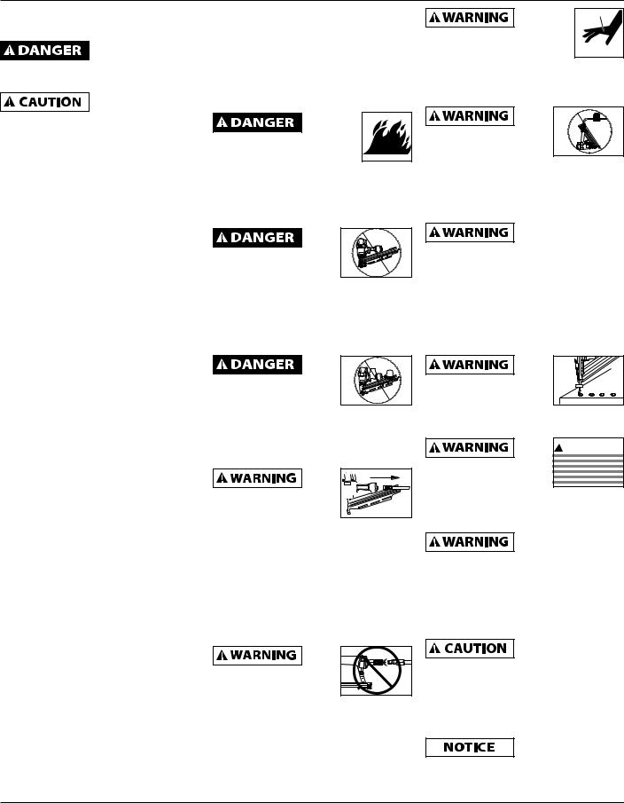
Danger indicates an imminently
hazardous situation which, if not avoided, WILL result in death or serious injury.
Warning indicates a potentially
hazardous situation which, if not avoided, COULD result in death or serious injury.
Caution indicates a potentially
hazardous situation which, if not avoided, MAY result in minor or moderate injury.
Notice indicates important
information, that if not followed, may cause damage to equipment.
NOTE: Information that requires special attention..
Important Safety Instructions
INSTRUCTIONS PERTAINING TO A RISK OF FIRE, ELECTRIC SHOCK, OR INJURY TO PERSONS
Models NS219500 |
Locate model and date code on tool and record below:
Model No..: _____________________
Date Code: _____________________
Retain these numbers for future reference..
When using tools, basic precautions should always be followed, including
the following:
California proposition 65
This product or
its power cord may contain chemicals known to the State of California to cause cancer and birth defects or other reproductive harm.
Wash hands after handling.
You can create
dust when you cut, sand, drill or grind materials such as
wood, paint, metal, concrete, cement, or other masonry. This dust often contains chemicals known to cause cancer, birth defects, or other reproductive harm. Wear protective gear.
REMINDER: Keep your dated proof of purchase for warranty purposes!
Attach it to this manual or file it for safekeeping.
Campbell Hausfeld Tools meet or exceed Industries’ Standards as set forth by the American National Standard |
IN715704AV 12/11 |
Institute/International Staple, Nail and Tool Association in ANSI/ISANTA SNT-101-2002.. |
|
© 2011 Campbell Hausfeld/Scott Fetzer |
For parts, product & service information |
|
visit www.chpower.com |
Operating Instructions
Important Safety Instructions |
|
able to create sparks resulting in the |
|
better control of the tool in |
|||||||
(Continued) |
|
ignition of the dust or fumes.. |
|
unexpected situations.. |
|||||||
General |
c.. |
Keep bystanders, children, and |
e.. |
Use safety equipment. A dust mask, |
|||||||
a.. |
To reduce the risks of |
|
|
visitors away while operating the |
|
non-skid safety shoes and a hard |
|||||
|
|
|
|||||||||
|
|
tool. Distractions are able to result in |
|
hat must be used for the applicable |
|||||||
|
electric shock, fire, and |
|
|
|
|||||||
|
|
|
the loss of control of the tool.. |
|
conditions.. |
||||||
|
injury to persons, read all |
|
|
|
|||||||
|
|
|
|
|
|
|
|
|
|
||
|
the instructions before |
|
Personal Safety |
f.. |
Always wear eye |
|
|||||
|
|
|
|||||||||
|
using the tool. |
a.. |
Stay alert. Watch what you are |
|
protection. |
|
|||||
b. |
Be thoroughly familiar with the |
g.. Always wear hearing |
|
||||||||
|
doing and use common sense |
|
|||||||||
|
controls and the proper use of the |
|
|
protection when using |
|
||||||
|
|
when operating the tool. Do not |
|
|
|||||||
|
equipment.. Follow all instructions.. |
|
|
the tool. Prolonged exposure to |
|||||||
|
|
use the tool while tired or under |
|
||||||||
|
Contact your Campbell Hausfeld |
|
|
high intensity noise is able to cause |
|||||||
|
|
the influence of drugs, alcohol, |
|
||||||||
|
representative if you have any |
|
|
hearing loss.. |
|||||||
|
|
or medication. A moment of |
|
||||||||
|
questions.. |
|
|
|
|
|
|
|
|||
|
|
inattention while operating the |
h.. Do not attach the hose or tool to |
||||||||
|
|
|
|
|
|||||||
c. |
Only persons well acquainted with |
|
tool increases the risk of injury to |
|
your body. Attach the hose to the |
||||||
|
these rules of safe operation should |
|
persons.. |
|
structure to reduce the risk of loss of |
||||||
|
be allowed to use the unit.. |
b.. |
Dress properly. Do not wear loose |
|
balance if the hose shifts.. |
||||||
|
|
Read and |
|
|
|
|
|
|
|||
|
|
|
clothing or jewelry. Contain long |
i.. |
Always assume that the tool |
||||||
|
|
|
|||||||||
|
|
understand tool |
|
hair. Keep hair, clothing, and |
|
contains fasteners. Do not point |
|||||
labels and manual. Failure to follow |
|
|
|||||||||
|
gloves away from moving parts. |
|
the tool toward yourself or anyone |
||||||||
warnings, dangers, and cautions could |
|
|
|||||||||
|
Loose clothes, jewelry, or long |
|
whether it contains fasteners or not.. |
||||||||
result in DEATH or SERIOUS INJURY. |
|
|
|||||||||
Work Area |
|
hair increases the risk of injury to |
j. |
|
|
|
Do not nail on |
||||
|
|
|
|
||||||||
|
persons as a result of being caught |
|
|
|
|||||||
|
|
|
|
|
top of another |
||||||
a.. |
Keep the work area clean and well |
|
|
|
|
|
|||||
|
|
|
|
|
|||||||
|
in moving parts.. |
|
nail. This is able to cause the nail to |
||||||||
|
lighted. Cluttered benches and dark |
c.. |
Avoid unintentional starting. |
|
be deflected and hit someone, or |
||||||
|
areas increase the risks of electric |
|
cause the tool to react and result in a |
||||||||
|
|
Be sure the switch is off before |
|
||||||||
|
|
|
risk of injury to persons. |
||||||||
|
shock, fire, and injury to persons.. |
|
|
||||||||
|
|
connecting to the air supply. Do not |
k.. |
|
|
|
Remove finger |
||||
b.. Do not operate the tool |
|
|
carry the tool with your finger on |
|
|
|
|||||
|
|
|
|
|
|
from the trigger |
|||||
|
|
|
|
|
|||||||
|
in explosive atmospheres, |
|
|
the switch or connect the tool to th |
|
|
|
|
|||
|
|
|
|
when not driving fasteners. Never |
|||||||
|
such as in the presence |
|
|
air supply with the switch on.. |
|
carry the tool with finger on trigger, |
|||||
|
of flammable liquids, |
|
d.. |
Do not overreach. Keep proper |
|
the tool is able to fire a fastener. |
|||||
|
|
|
|||||||||
|
|
|
|
|
|
|
|
|
|
||
gases, or dust. The tool is |
footing and balance at all times. |
|
|
|
Proper footing and balance enables |
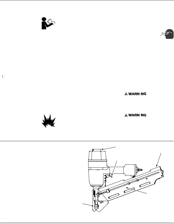
Tool Components and Specifications
•Requires: 2..5 SCFM with 16 nails per minute @ 90 psi
•Air inlet: 1/4 inch NPT
•NAIL SIZE RANGE: 2 inch to 3-1/2 inch
•NAIL SHANK RANGE: 0..113 inch to 0..131 inch
•MAGAZINE CAPACITY: 60 - 75
•WEIGHT: 8 lbs.., 2 oz..
•LENGTH: 19-1/2 inch
•HEIGHT: 15-1/8 inch
•MAXIMUM PRESSURE: 120 psi
•PRESSURE RANGE: 70 psi – 120 psi
Work
Contract
Element
Adjustable Direction
Exhaust Deflector Nail Loading
Area
Trigger
 Magazine
Warning Labels (Backside)
 Debris Shield
 Nail Discharge Area
www.chpower.com
2
NS219500
Important Safety Instructions (Continued)
Always remain in a firmly balanced
position when using or handling the tool.
Avoid long extended periods of work
with the tool. Stop using the tool if you feel pain in hands or arms.
Tool Use and Care
a..Use clamps or another practical way to secure and support the workpiece to a stable platform. Holding the work by hand or against the body is unstable and is able to lead to loss of control..
b..Do not force the tool. Use the correct tool for the application.. The correct tool will do the job better and safer at the rate for which the tool is designed..
c..Do not use the tool if the switch does not turn the tool on or off. Any tool that cannot be controlled with the switch is dangerous and must be repaired..
d..Disconnect the tool from the air source before making any
adjustments, changing accessories, loading, unloading, or storing
the tool. Such preventive safety measures reduce the risk of starting the tool unintentionally..
e..Store the tool when it is idle out of reach of children and other untrained persons. A tool is
dangerous in the hands of untrained users..
f..Maintain the tool with care. Keep a cutting tool sharp and clean.. A
properly maintained tool, with sharp cutting edges reduces the risk of binding and is easier to control..
g..Check for misalignment or binding of moving parts, breakage of parts, and any other condition that affects the tool’s operation. If damaged, have the tool serviced before using.. Many accidents are caused by poorly maintained tools.. There is a risk of bursting if the tool is damaged..
h..Use only accessories that are identified by the manufacturer for the specific tool model. Use of an
accessory not intended for use with the specific tool model, increases the risk of injury to persons..
i.Selecting an appropriate tool actuation system, taking into consideration the work application for which the tool is used..
Never use
gasoline or other flammable liquids to clean the tool. Never use
the tool in the presence of flammable liquids or gases. Vapors could ignite by a spark and cause an
explosion which will result in death or serious personal injury.
Do not remove, tamper with, or otherwise cause the Work Contact
Element (WCE) or trigger to become inoperable. Do not operate any tool which has been modified in a like fashion. Death or serious personal injury could result.
Do not touch the trigger unless driving fasteners. Never attach air line to
tool or carry tool while touching the trigger. The tool could eject a fastener which will result in death or serious personal injury.
Always disconnect the 


 tool from the power


 source when unattended,
performing any maintenance or repair, clearing a jam, loading, unloading,
or moving the tool to a new location. Always reconnect the air line AFTER loading any fasteners. Do not load the tool with fasteners when either the trigger is depressed or the Work Contact Element (WCE) is engaged. The tool could eject a fastener causing death or serious personal injury.
Always fit tool with a fitting or hose coupling on or near the tool in
such a manner that all compressed air in the tool is discharged at the time the fitting or hose coupling is disconnected. Do not use a check valve or any other fitting which allows air to remain in the tool. Death or serious personal injury could occur.
Never place hands or any other body parts in the fastener discharge area of
the tool. The tool might eject a fastener and could result in death or serious personal injury.
Never carry the tool by
the air hose or pull the hose to move the tool
or a compressor. Keep hoses away from heat, oil and sharp edges. Replace any hose that is damaged, weak or worn. Personal injury or tool damage could occur.
Always assume the tool contains
fasteners. Respect the tool as a working implement; no horseplay. Always keep others at a safe distance from the work area in case of accidental discharge of fasteners. Do not point the tool toward yourself or anyone whether it contains fasteners or not. Accidental triggering of the tool could result in death or serious personal injury.
Do not drive a fastener on top of other fasteners. The fastener
could glance and cause death or a serious puncture wound.
! WARNING
Do not operate or allow anyone else to operate the tool if any warnings
or warning labels are not legible. Warnings or warning labels are located on the tool magazine and body.
Do not drop or throw the tool.
Dropping or throwing the tool can result in damage that will make the tool unusable or unsafe. If the tool has been dropped or thrown, examine the tool closely for bent, cracked or broken parts and air leaks. STOP and repair before using or serious injury could occur.
Always check that the Work Contact
Element (WCE) is operating properly. A fastener could accidentally be driven if the WCE is not working properly. Personal injury may occur (See "Checking the Work Contact Element" Section).
Avoid using the tool when the
magazine is empty. Accelerated wear on the tool may occur.
www.chpower.com
3
Operating Instructions
Important Safety Instructions |
operation, breakage of the tool or |
|
Operating Instructions |
||||||
(Continued) |
serious injury to persons.. Use only |
|
Lubrication |
|
|||||
Clean and check all |
clean, dry, regulated compressed air |
|
|||||||
This tool requires lubrication before |
|||||||||
air supply hoses |
at the rated pressure or within the |
|
|||||||
and fittings before connecting the |
rated pressure range as marked on |
|
using the tool for the first time and |
||||||
tool to an air supply. Replace any |
the tool.. Always verify prior to using |
before each use.. If an inline oiler is |
|||||||
damaged or worn hoses or fittings. |
the tool that the air source has been |
used, manual lubrication through the |
|||||||
Tool performance or durability may be |
|||||||||
adjusted to the rated air pressure or |
air inlet is not required on a daily basis.. |
||||||||
reduced. |
|||||||||
Service |
within the rated air-pressure range.. |
|
The work surface |
||||||
b.. Never use oxygen, carbon dioxide, |
|
|
can become |
|
|||||
a.. Tool service must be performed only |
|
damaged by excessive lubrication. |
|||||||
combustible gases or any bottled |
|
||||||||
by qualified repair personnel. |
|
Proper lubrication is the owner’s |
|||||||
gas as an air source for the tool. |
|
||||||||
|
responsibility. Failure to lubricate the |
||||||||
b.. When servicing a tool, use only |
|
||||||||
Such gases are capable of explosion |
tool properly will dramatically shorten |
||||||||
identical replacement parts. Use |
and serious injury to persons.. |
|
the life of the tool and void your |
||||||
only authorized parts. |
|
|
|
|
|
warranty. |
|
||
|
|
|
|
|
|
|
|
||
c.. Use only the lubricants supplied |
|
Do not use |
|
|
1. |
Disconnect the air |
|
||
|
O CO2 |
|
|
supply from the tool |
|
||||
with the tool or specified by the |
any type of reactive gases, |
|
|
|
|
||||
manufacturer. |
including, but not limited to, |
|
|
|
to add lubricant.. |
|
|||
oxygen and combustible |
|
|
|
|
|
|
|||
Do not make any |
|
|
|
|
|
|
|||
gases, as a power source. Use filtered, |
|
|
|
|
|||||
modifications to |
|
2. |
Turn the tool so the air |
|
|||||
lubricated, regulated compressed air |
|
|
|||||||
the tool without first obtaining written |
|
|
inlet is facing up.. Place |
|
|||||
only. Use of a reactive gas instead of |
|
|
OIL |
||||||
approval from Campbell Hausfeld. Do |
compressed air may cause the tool |
|
|
4-5 drops of 30 W non- |
|
||||
not use the tool if any shields or guards |
|
|
|
||||||
to explode which will cause death or |
|
|
detergent oil into air inlet.. |
|
|||||
are removed or altered. Do not use the |
|
|
|
||||||
serious personal injury. |
|
|
|
|
|
||||
|
|
|
|
Do not use detergent |
|
||||
tool as a hammer. Personal injury or |
|
|
|
|
|
||||
|
|
|
|
|
|
|
|||
tool damage may occur. |
|
|
|
|
|
|
oils, oil additives, or airtool oils.. |
||
Disconnect air |
Use only a pressure-regulated |
|
|
|
Air tool oils contain solvents which |
||||
supply and release |
|
|
|
will damage the tool's internal |
|||||
compressed air source to limit |
120 psi |
|
|||||||
tension from the pusher before |
|
components.. |
|
||||||
pressure supplied to the |
|
|
|
||||||
attempting to clear jams because |
|
|
|
|
|
|
|||
tool. The regulated pressure must not |
|
3. After adding oil, run |
|
||||||
fasteners can be ejected from the front |
|
|
|||||||
of the tool. Personal injury may occur. |
exceed 120 psi. If the regulator fails, the |
|
tool briefly.. Wipe off |
|
|||||
|
pressure delivered to the tool must not |
|
any excess oil from |
|
|||||
Air Source |
exceed 200 psi. The tool could explode |
|
|
|
|||||
|
|
the cap exhaust.. |
|
||||||
a.. Never connect to an air source that |
which will cause death or serious |
|
|
|
|||||
|
|
|
|
||||||
personal injury. |
|
|
|
Recommended Hookup |
|
||||
is capable of exceeding 200 psi. |
|
|
|
|
|||||
|
|
|
|
|
|
||||
Save These Instructions |
|
|
|
|
|||||
Over pressurizing the tool is able |
|
The illustration below shows the |
|||||||
|
Do Not Discard |
|
|
||||||
to result in bursting, abnormal |
|
|
|
recommended hookup for the tool.. |
|||||
|
|
|
|
|
|||||
Recommended Hookup |
|
|
|
|
|
|
|
|
|
|
|
|
Quick |
Regulator |
|
||||
|
|
|
|
|
|
|
|||
|
Quick |
Quick Plug |
Coupler |
|
|
|
|
||
Quick Plug |
Coupler |
(Optional) |
(Optional) |
|
|
|
|
||
Air Hose
Lubricator
Filter
www.chpower.com
4
|
|
|
|
|
|
NS219500 |
Operating Instructions |
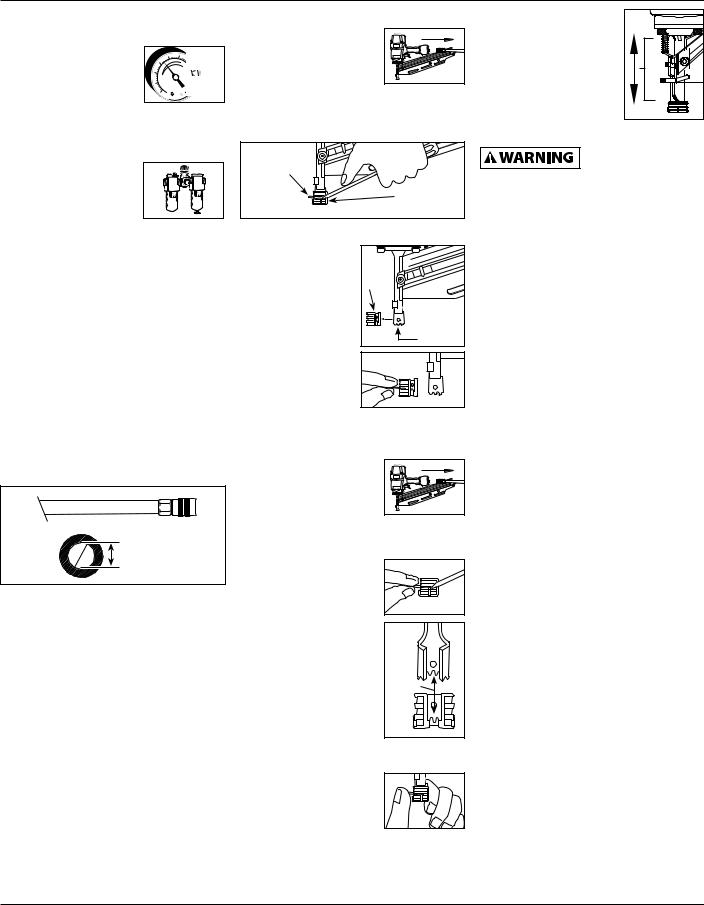
Removing No-Mar Decking Tip |
6. Check that the WCE |
||||
(Continued) |
|
1. |
Disconnect air supply |
and trigger move |
||
1. |
The air compressor |
70 psi |
|
from nailer.. |
|
up and down freely |
|
|
without sticking or |
||||
|
must be able to |
|
|
|
||
|
Min. |
|
|
|
||
|
|
|
|
binding.. |
||
|
maintain a minimum |
120 psi |
|
|
|
|
|
of 70 psi when the |
Max. |
2. |
Remove all fasteners from magazine |
|
|
|
|
|
||||
|
tool is being used.. An inadequate |
|
(See UNLOADING THE NAILER).. |
|
||
|
air supply can cause a loss of power |
3. |
Remove no-mar tip retaining ring.. |
Operational Mode |
||
|
and inconsistent driving.. |
|
|
Retaining |
|
Always know the |
|
|
|
|
|
||
2. |
An oiler can be used |
|
|
|
operational mode of |
|
|
|
Ring |
|
|||
|
to provide oil |
|
|
|
|
the tool before using. Failure to know |
|
|
|
|
No-Mar Tip |
the operational mode could result in |
|
|
circulation through |
|
|
|
||
|
|
|
|
death or serious personal injury. |
||
|
the tool.. A filter can |
|
|
|
|
|
|
|
|
|
|
|
|
|
be used to remove liquid and solid |
|
|
|
Single Cycle Mode |
|
|
impurities which can rust or “gum |
4. |
Pry no-mar tip |
No-Mar |
When the black trigger is installed, |
|
|
up” internal parts of the tool.. |
|
|
away from the |
nailer is in single cycle mode.. This |
|
3. Always use air supply hoses with |
|
work contact |
Tip |
method is recommended when precise |
||
|
|
|||||
|
a minimum working pressure |
|
|
element.. |
|
nail placement is required.. Operation in |
|
rating equal to or greater than the |
|
|
Work |
this mode requires trigger to be pulled |
|
|
pressure from the power source if a |
|
|
Contact |
each time a nail is driven.. |
|
|
regulator fails, or 150 psi, whichever |
|
|
Element |
Nailer can be actuated by depressing |
|
|
5. |
Replace retaining |
|
|||
|
is greater.. Use 3/8 inch air hose for |
|
the Work Contact Element (WCE) |
|||
|
|
ring onto no-mar |
|
|||
|
runs up to 50 feet.. Use 1/2 inch air |
|
|
against work surface followed by |
||
|
|
tip, then store tip |
|
|||
|
hoses for 50 foot run or longer.. For |
|
|
pulling the trigger.. |
||
|
|
in safe place for |
|
|||
|
better performance, install a 3/8 inch |
|
|
The trigger must be released after each |
||
|
|
future use.. |
|
|||
|
quick plug (1/4 inch NPT threads) |
|
|
|||
|
|
|
fastener is driven to allow tool to reset.. |
|||
|
|
|
|
|||
|
with an inside diameter of ..315 inch |
Installing No-Mar Decking Tip |
||||
|
Since the tool can only be actuated |
|||||
|
(8mm) on the tool and a 3/8 inch |
1. |
Disconnect air supply |
|||
|
quick coupler on the air hose.. |
|
by first removing the finger from the |
|||
|
|
|
from nailer.. |
|
||
|
|
|
|
|
trigger, this is considered to be a more |
|
|
|
|
|
|
|
|
|
150 psi or greater |
|
|
|
|
restrictive mode of operation, suitable |
|
|
|
2. Remove all fasteners from magazine |
for less experienced users.. |
||
|
|
|
Bottom trip Mode |
|||
|
3/8 inch I..D.. |
|
|
(See UNLOADING THE NAILER).. |
||
|
|
3. |
Remove retaining |
|
When the red trigger is installed, the |
|
|
|
|
|
|||
|
|
|
|
ring from no-mar tip.. |
nailer is in bottom trip mode.. This |
|
4. Use a pressure regulator on the |
|
|
|
method is recommended when less |
||
|
compressor, with an operating |
|
|
|
precise nail placement is required.. |
|
|
pressure of 0 - 125 psi.. A pressure |
4. |
Carefully place |
|
Operation in this mode requires trigger |
|
|
regulator is required to control |
|
no-mar tip over the |
to be depressed with nailer off of |
||
|
the operating pressure of the tool |
|
end of work contact |
the work surface.. Then, the nose of |
||
|
between 70 and 120 psi.. |
|
|
element.. Position tip |
the nailer is tapped against the work |
|
|
|
|
|
onto WCE making |
Grooves |
surface causing a nail to be driven.. |
No-Mar Decking Tip |
|
|
|
|||
|
|
certain serrated |
|
Each time the Work Contact Element is |
||
The no-mar decking tip is designed |
|
|
||||
|
gooves on each piece |
depressed, a nail is driven into the work |
||||
to eliminate marks caused by the |
|
|
||||
|
|
are in line and fit |
|
surface.. Extreme care should be taken |
||
serrated work contact element (WCE).. |
|
|
||||
|
snugly together.. |
|
because a nail will be driven when the |
|||
The no-mar tip may be removed if not |
|
|
||||
5. |
Position retaining |
|
WCE is pressed against any surface.. |
|||
required (See REMOVING NO-MAR |
|
|||||
|
ring on no-mar tip |
|
Since the tool can be actuated without |
|||
DECKING TIP).. Use tool in single cycle |
|
|
||||
mode (SEE OPERATIONAL MODES) when |
|
and press firmly in |
|
removing the finger from the trigger, |
||
no-mar tip is in place.. |
|
|
place.. |
|
this is considered to be a less restrictive |
|
|
|
|
|
|
|
mode, suitable for more experienced |
|
|
|
|
|
|
users.. |
|
|
|
|
|
|
www.chpower.com |
5

Operating Instructions
Operating Instructions (Continued)
mode conversion
To convert the tool from one mode to the other:
1.Remove o-ring on the side of trigger pin..
2.Remove trigger pin, trigger, and trigger spring..
3.Switch out only the trigger..
3. Make sure the trigger and work contact element (WCE) move freely up and down without sticking or binding..
4. Reconnect air supply to the tool..
LOADINg the nailer
1.Always disconnect the tool from the air supply before loading fasteners..
2. |
Pull nail pusher |
Nail Pusher |
Latch |
|
mechanism back |
||
|
Mechanism |
|
|
|
until pusher |
|
|
|
|
|
|
|
engages with |
|
|
|
magazine latch.. |
|
|
4.Replace trigger spring, trigger, trigger pin, and o-ring..
Do not attempt to modify the trigger components in any manner and do not attempt to use any other trigger components other than those intended for this tool..
Contact your Campbell Hausfeld representative if you have any questions..
Mode Conversion |
Trigger spring |
O-ring |
Trigger |
Trigger pin |
Operating A Sequential Trip Tool
Check the operation of the Work Contact
Element (WCE) trip mechanism before each use. The WCE must move freely without binding through its entire travel distance. The WCE spring must return the WCE to its fully extended position after being depressed. Do not operate the tool if the WCE trip mechanism is not operating properly. Personal injury may occur.
1. Disconnect the air supply from the tool..
2. Remove all fasteners from the magazine (see Loading / Unloading)..
5. Depress the Work
Contact Element (WCE) against the work surface
without pulling the trigger.. The tool must not
operate.. Do not use the tool if it operates without pulling the trigger.. Personal injury may result..
6.Remove the tool from the work
surface.. The Work Contact
Element (WCE) must return
to its original  down position.. The tool must not operate.. Do not use the tool if it operates while lifted from the work surface.. Personal injury may result..
7. Pull the trigger
and depress the 


 work contact


 element (WCE)

against the work surface.. The tool
MUST NOT operate IF IN single cycle mode (black trigger).. The tool MUST operate IF IN bottom trip mode (red trigger)..
8. Depress the Work Contact Element (WCE) against the
work surface..
Pull the trigger.. The tool MUST operate..
An improperly functioning tool
must not be used. Do not actuate the tool unless the tool is placed firmly against the work piece.
3. Load strips of fasteners into the magazine slot.. Make sure that the nails are placed into tool at the proper orientation..
4.Squeeze the pusher and the
latch together to unlatch pusher.. Make sure the head of the last  nail is under the head of the pusher..
UNLOADING THE Nailer
1.Always unload all fasteners before removing tool from service.. Unloading is the reverse of loading, except always disconnect the air hose before unloading..
2. |
Pull nail pusher |
Nail Pusher Latch |
|
mechanism back |
Mechanism |
|
until pusher |
|
|
|
|
|
engages with |
|
|
magazine latch.. |
|
3. Hold tool upright so nails will
slide backwards toward magazine slot..
4.Squeeze the pusher and
latch together to unlatch the pusher once all nails have been removed..
www.chpower.com
6
NS219500
Operating Instructions (Continued)
Adjusting the Nail Penetration
The NS219500 is equipped with an adjustable depth of drive feature.. This allows the user to determine how deep a fastener will be driven into the work surface..
1.Adjust the operating pressure to a pressure which will consistently drive the fasteners.. Do not exceed the maximum operating pressure of the nailer of 120 psi..
2.To adjust the depth-of-drive, loosen the 4mm bolt on the top of nose.. To increase depth, push WCE in toward nose as much as desired.. Re-tighten bolt.. To decrease depth, pull WCE out as much as desired.. Re-tighten bolt..
3.Make sure that the trigger and work contact element
(WCE) move freely up and down without binding or sticking after each adjustment..
AnTI-DRY FIRE
These tools are equipped with an AntiDry Fire feature.. This prevents the WCE from being pushed in when only a few nails remain.. Simply load new nail clip behind remaining nails to continue shooting..
Adjusting The Direction Of The
Exhaust
The tool is equipped |
|
|
with an adjustable |
|
|
direction exhaust |
Rotate |
|
deflector.. This is |
||
|
intended to allow the user to change the direction of the exhaust.. Simply twist the deflector to any direction desired..
Clearing A Jam From The Tool
1. Disconnect the air supply from the tool..
2. Remove all  nails from


 the magazine
 (see "Loading/
 Unloading The


 Nailer").. Failure
 to do so will
  cause the nails to eject from the front of the nailer..
3. Insert a screw-
driver into the nose of the tool..
Push up on the driver blade to free the jammed nail..
4. Grab the jammed nail with pliers and remove..
User-Maintenance Instructions
Technical Service
Please call our Tool Hotline at 1-800- 543-6400 with any questions regarding the operation or repair of this tool or for additional copies of this manual..
Fastener And Replacement Parts
Use only genuine Campbell Hausfeld
fasteners (or equivalent - see Fastener Interchange Information). Use only genuine Campbell Hausfeld replacement parts. Never substitute parts. Do not use modified parts or parts which will not give equivalent performance to the original equipment. Tool performance, safety and durability could be reduced. When ordering replacement parts or fasteners, specify by part number.
Tool Repair
Only qualified personnel should repair the tool and they should use genuine Campbell Hausfeld replacement parts and accessories, or parts and accessories which perform equivalently..
Assembly Procedure For Seals
When repairing a tool, the internal parts must be cleaned and lubricated.. Parker O-lube or equivalent must be used on all o-rings.. Each o-ring must be coated with O-lube before assembling.. A small amount of oil must be used on all moving surfaces and pivots.. After reassembling, a few drops of 30W non-detergent oil or equivalent, must be added through the air line before testing..
Storage
The stapler should be stored in a cool dry place..
7

Notes

NS219500
Fasteners Information
Nails used in the Campbell Hausfeld NS219500 Framing Nailers will also work in Campbell Hausfeld NS21900, Sears 18465, Porter Cable FR350, Hitachi NR83A, Senco FramePro 702XP, 752XP, Ridgid R350RHA, and DeWalt D51844, D51845..
Troubleshooting Chart
Stop using stapler immediately if any of the following problems occur. Serious personal injury could occur. Any repairs or replacements must be done by a Qualified Service Person or Authorized Service Center.
Symptom |
Possible Cause(s) |
Corrective Action |
||
Air leaking at trigger valve |
O-Rings in trigger valve housing are |
Replace o-rings and check operation of Work |
||
area.. |
damaged |
Contact Element (WCE) |
||
|
|
|
|
|
Air leaking between housing |
1. Damaged O-Rings |
1. |
Replace o-rings |
|
and nose.. |
2. |
Damage to bumper |
2. |
Replace bumper |
|
||||
|
|
|
|
|
Air leaking between housing |
1. |
Loose screws |
1. |
Tighten screws |
and cap.. |
2. |
Damaged gasket |
2. |
Replace gasket |
|
||||
|
|
|
|
|
Nailer skips driving nail |
1. |
Worn bumper |
1. |
Replace bumper |
|
2. |
Dirt in nose piece |
2. |
Clean drive channel |
|
3. |
Dirt or damage prevent staples or pusher |
3. |
Clean magazine |
|
|
from moving freely in magazine |
|
|
|
4. |
Damaged pusher spring |
4. |
Replace spring |
|
5. |
Inadequate air flow to stapler |
5. |
Check fitting, hose, or compressor |
|
6. |
Worn O-Ring on piston or lack of |
6. |
Replace and lubricate o-rings |
|
|
lubrication |
|
|
|
7. |
Damaged O-Ring on trigger valve |
7. |
Replace o-rings |
|
8. |
Air leaks |
8. |
Tighten screws and fittings |
|
9. |
Cap gasket leaking |
9. |
Replace gasket |
|
|
|
|
|
Nailer runs slow or has loss |
1. |
Nailer not lubricated sufficiently |
1. |
Lubricate nailer |
of power |
2. |
Broken spring in cylinder cap |
2. |
Replace spring |
|
||||
|
3. |
Exhaust port in cap is blocked |
3. |
Replace damaged internal parts |
|
|
|
|
|
Nails are jammed in nailer |
1. Guide on driver is worn |
1. |
Replace guide |
|
|
2. |
Nails are not correct size |
2. |
Use only recommended nails |
|
3. |
Nails are bent |
3. |
Replace with undamaged nails |
|
4. |
Magazine or nose screws are loose |
4. |
Tighten screws |
|
5. |
Driver is damaged |
5. |
Replace driver |
www.chpower.com
9

Operating Instructions
Limited Warranty
1.DURATION: From the date of purchase by the original purchaser as follows: One (1) Year..
2.WHO GIVES THIS WARRANTY (WARRANTOR): Campbell Hausfeld / Scott Fetzer Company, 100 Production Drive, Harrison, Ohio, 45030, Telephone: (800) 543-6400
3..WHO RECEIVES THIS WARRANTY (PURCHASER): The original purchaser (other than for purposes of resale) of the Campbell Hausfeld product..
4..WHAT PRODUCTS ARE COVERED BY THIS WARRANTY: This Campbell Hausfeld nailer or stapler..
5..WHAT IS COVERED UNDER THIS WARRANTY: Substantial defects in material and workmanship which occur within the duration of the warranty period with the exceptions below..
6..WHAT IS NOT COVERED UNDER THIS WARRANTY:
A.Implied warranties, including those of merchantability and FITNESS FOR A PARTICULAR PURPOSE ARE LIMITED FROM THE DATE OF ORIGINAL PURCHASE AS STATED IN THE DURATION.. If this product is used for commercial, industrial or rental purposes, the warranty will apply for ninety (90) days from the date of purchase.. Some States do not allow limitation on how long an implied warranty lasts, so the above limitations may not apply to you..
B.ANY INCIDENTAL, INDIRECT, OR CONSEQUENTIAL LOSS, DAMAGE, OR EXPENSE THAT MAY RESULT FROM ANY DEFECT, FAILURE, OR MALFUNCTION OF THE CAMPBELL HAUSFELD PRODUCT.. Some States do not allow the exclusion or limitation of incidental or consequential damages, so the above limitation or exclusion may not apply to you..
C.Any failure that results from an accident, purchaser’s abuse, neglect or failure to operate products in accordance with instructions provided in the owner’s manual(s) supplied with product.. Accident, purchaser’s abuse, neglect or failure to operate products in accordance with instructions shall also include the removal or alteration of any safety devices.. If such safety devices are removed or altered, this warranty is void..
D.Normal adjustments which are explained in the owner’s manual(s) provided with the product..
E.Items or service that are normally required to maintain the product, e..g.. o-rings, springs, bumpers, debris shield, driver blades, gaskets, packings or seals, lubricants, or any other expendable part not specifically listed.. These items will only be covered for ninety (90) days from date of original purchase.. Underlined items are warranted for defects in material and workmanship only..
7.RESPONSIBILITIES OF WARRANTOR UNDER THIS WARRANTY: Repair or replace, at Warrantor’s option, products or components which are defective, have malfunctioned and/or failed to conform within the duration of the specific warranty period..
8.RESPONSIBILITIES OF PURCHASER UNDER THIS WARRANTY:
A.Provide dated proof of purchase and maintenance records..
B.Call Campbell Hausfeld (800) 543-6400 to obtain your warranty service options.. Freight costs must be borne by the purchaser..
C.Use reasonable care in the operation and maintenance of the products as described in the owner’s manual(s)..
9.WHEN WARRANTOR WILL PERFORM REPAIR OR REPLACEMENT UNDER THIS WARRANTY: Repair or replacement will be scheduled and serviced according to the normal work flow at the servicing location, and depending on the availability of replacement parts..
This Limited Warranty applies in the United States, Canada and Mexico only and gives you specific legal rights.. You may also have other rights which vary from state to state or country to country..
www.chpower.com
10
 Loading...