


See Warranty on page 16 for important information about commercial use of this product.
Operating Instructions and Parts Manual |
GN5060, GN6575 |
|
|
Please read and save these instructions. Read carefully before attempting to assemble, install, operate or maintain the product described. Protect yourself and others by observing all safety information. Failure to comply with instructions could result in personal injury and/or property damage! Retain instructions for future reference.
Generator
|
|
|
|
|
RAN |
|
|
|
|
|
|
SU |
CE |
PR |
|||
|
|
|
S |
|
|
|||
|
|
A |
|
|
|
|
O |
|
|
Y |
|
|
|
|
|
G |
|
T |
|
|
|
|
|
|
R |
|
I |
|
|
Need |
A |
||||
U AL |
|
|
|
M |
||||
Q |
|
|
|
|
|
|
|
|
Assistance?
Call Us First!
1-800-803-1436
Table of Contents
Description . . . . . . . . . . . . . . . . . . . . . .1
Unpacking . . . . . . . . . . . . . . . . . . . . . . .1
Specifications. . . . . . . . . . . . . . . . . . . . .1
Safety Guidelines . . . . . . . . . . . . . . . . .2
General Safety Information . . . . . . 2 - 3
Glossary of Terms . . . . . . . . . . . . . . . . .3
Pre-operation . . . . . . . . . . . . . . . . . 3 - 4
Operation . . . . . . . . . . . . . . . . . . . . 5 - 6
Maintenance . . . . . . . . . . . . . . . . . . . . .6
Storage . . . . . . . . . . . . . . . . . . . . . . . . .6
Troubleshooting Chart . . . . . . . . . . . . .7
Service Record . . . . . . . . . . . . . . . . . . . .8
Wiring Diagram. . . . . . . . . . . . . . . . . . .9
Generator Assembly . . . . . . . . . . 10 - 11
Alternator Assembly . . . . . . . . . . 12 - 13
Control Panel Assembly . . . . . . . 14 - 15
Warranty . . . . . . . . . . . . . . . . . . . . . . .16
Description
These Campbell Hausfeld generators are powered by gasoline engines. Each unit is equipped with 120V and 230V outlets which provide continuous smooth power for the task at hand. These outlets are protected by GFCI (Ground Fault Circuit Interrupters) and thermal circuit breakers.
Unpacking
When unpacking unit, inspect carefully for any damage that may have occurred during transit. Make sure any loose fittings, bolts, etc., are tightened before putting unit into service. In case of questions, damaged or missing parts, please call 1-800-803-1436 for customer assistance. Have the serial number, model number, and parts list (with missing parts circled) before calling.
DO NOT RETURN
STOP! THE PRODUCT TO
THE RETAILER!
READ & FOLLOW ALL INSTRUCTIONS
SAVE THESE INSTRUCTIONS
DO NOT DISCARD
Specifications
Model GN5060
Engine . . . . . . . . . . . Honda GX270 Valve Type . . . . . . . . . . . . . . .OHV Engine Size/Type. . . . . . 270cc/4 Stroke Start Type. . . . . . . . . . Manual Recoil Alternator Type . . . . . 2 Pole, Brushless Phase/Frequency. . . . . . . . 1 PH/60 Hz Alternator Rating . . . . . . . . . 5.2 KVA Fuel Tank Cap . . . . 6 Gallons [22.7 Liter]
Model GN6575
Engine . . . . . . . . . . . Honda GX390 Valve Type . . . . . . . . . . . . . . .OHV Engine Size/Type. . . . . . 390cc/4 Stroke Start Type. . . . . . . . . . Manual Recoil Alternator Type . . . . . 2 Pole, Brushless Phase/Frequency. . . . . . . . 1 PH/60 Hz Alternator Rating . . . . . . . . . 6.8 KVA Fuel Tank Cap . . . . 6 Gallons [22.7 Liter]
REMINDER: Keep your dated proof of purchase for warranty purposes! Attach it to this manual or file it for safekeeping.
© 2012 Campbell Hausfeld/Scott Fetzer |
For parts, product & service information |
IN954800AV 3/12 |
|
visit www.chpower.com or call 1-800-803-1436 |
|
Operating Instructions and Parts Manual
Safety Guidelines |
|
|
• Be sure that the generator is placed |
|
This manual contains information |
|
|
on a flat level surface prior to and |
|
|
|
during operation. The generator |
||
that is very important to know and |
|
|
||
|
|
must not slide or shift during |
||
understand. This information is |
|
|
||
|
|
operation. |
||
provided for SAFETY and to PREVENT |
|
|
||
|
|
|
||
EQUIPMENT PROBLEMS. To help |
|
|
• Keep all persons away from the |
|
recognize this information, observe the |
|
|
generator during operation. |
|
following symbols. |
|
|
• Do not allow persons wearing |
|
Danger indicates |
|
|
||
|
|
loose clothing or jewelry to start |
||
an imminently |
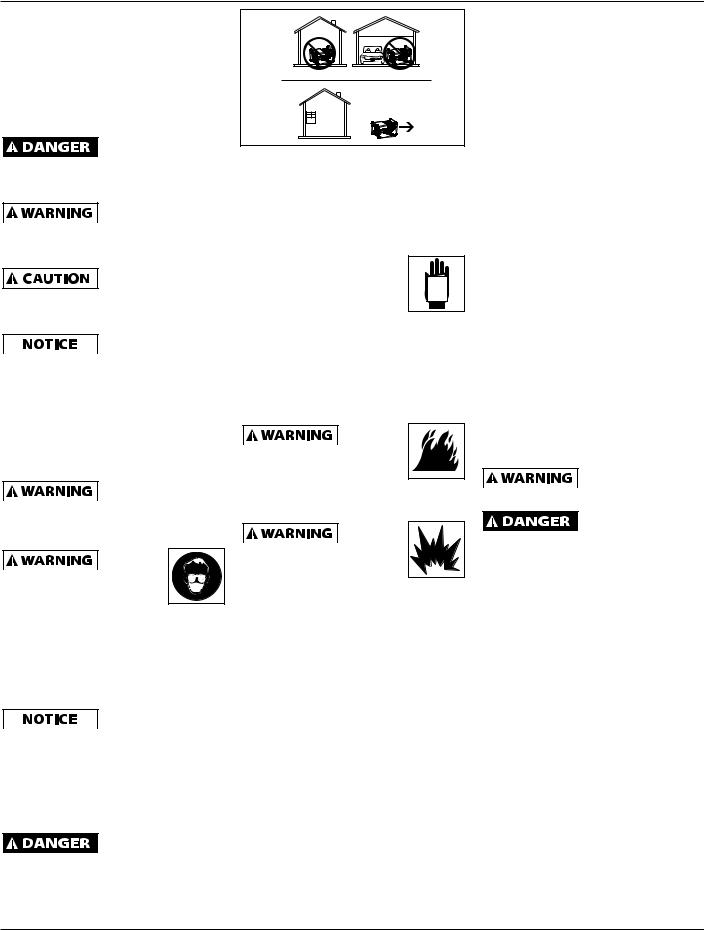
• NEVER use inside a house or |
|
or operate the generator. Loose |
|
hazardous situation which, if not |
|
|||
garage, EVEN IF doors and windows |
clothing or jewelry may become |
|||
avoided, WILL result in death or serious |
||||
are open. |
|
entangled in moving components, |
||
injury. |
|
|||
Warning indicates |
• Only use OUTSIDE and far away |
causing equipment damage and or |
||
personal injury. |
||||
a potentially |
from windows, doors and vents. |
|||
|
||||
hazardous situation which, if not |
GENERAL SAFETY |
|
• Keep all persons away from parts |
|
avoided, COULD result in death or |
|
that move or become hot during |
||
serious injury. |
• Before starting or |
|
||
|
operation. |
|||
Caution indicates |
|
|||
servicing any generator, |
|
• Be sure all powered devices are |
||
a potentially |
|
|||
read and understand all |
MANUAL |
|||
hazardous situation which, if not |
|
shut off prior to connecting them |
||
instructions. Failure to |
|
|||
avoided, MAY result in minor or |
|
to the generator. |
||
follow safety precautions |
|
|||
moderate injury. |
|
• Keep the generator clean and well |
||
Notice indicates |
or instructions can cause equipment |
|||
maintained at all times. |
||||
important |
damage and/or serious personal |
|||
information, that if not followed, may |
injury or death. Engine instructions |
• Be sure that all tools and appliances |
||
cause damage to equipment. |
for these units are contained in |
are in good repair and are properly |
||
|
||||
NOTE: Information that requires special |
a separate manual. Retain all |
|
grounded. Use devices that have |
|
attention. |
manuals for future reference. |
|
three prong power cords. If an |
|
|
FUEL AND |
|
extension cord is used, be sure |
|
General Safety Information |
VAPORS |
|
that it has three prongs for proper |
|
ARE EXTREMELY FLAMMABLE! |
|
grounding. |
||
CALIFORNIA PROPOSITION 65 |
|
|||
Allow engine to cool at |
|
Do not operate this |
||
The engine exhaust |
least two (2) minutes before |
|
generator on wet |
|
from this product |
refueling. Do not use gasoline/ethanol |
surfaces or in the rain. |
||
contains chemicals known to the State |
blends with greater than 15% ethanol. |
Shut off the engine |
||
of California to cause cancer, birth |
Never |
|
||
|
and disconnect the |
|||
defects, or other reproductive harm. |
operate |
|
spark plug wire before performing any |
|
You can |
this generator in an explosive |
|
service or maintenance to the unit. |
|
create |
or flammable atmosphere or |
|
• Use only unleaded fuel. Do not |
|
dust when you cut, sand, drill |
poorly ventilated area. |
|
refill the fuel tank while the engine |
|
or grind materials such as |
|
|
||
• Never use this generator for |
|
is running. Use precautions to |
||
wood, paint, metal, concrete, |
|
|||
any application other than that |
prevent fuel spillage during refills. |
|||
cement, or other masonry. This dust |
||||
specified by the manufacturer. |
Be sure the fuel tank cap is securely |
|||
often contains chemicals known to |
||||
Never operate this generator under |
in place before starting the engine. |
|||
cause cancer, birth defects, or other |
||||
reproductive harm. Wear protective |
conditions not approved by the |
Clean up any spilled fuel before |
||
gear. |
manufacturer. Never attempt to |
starting the engine. Allow engine |
||
EMISSIONS |
modify this generator to perform |
to cool for at least two minutes |
||
in any manner not intended by the |
before refueling. Do not add fuel |
|||
Engines that are |
||||
manufacturer. |
|
while smoking or if unit is near |
||
certified to comply |
|
|||
• For maintenance and repairs, |
|
any sparks or open flames. Do not |
||
with U.S. EPA emission regulations for |
|
|||
|
overfill tank - allow room for fuel |
|||
SORE (Small Off Road Equipment), are |
use only products and parts |
|
||
|
to expand. Always keep nozzle in |
|||
certified to operate on regular unleaded |
recommended by the manufacturer. |
|||
contact with tank during fueling. |
||||
gasoline, and may include the following |
• Be sure that the generator is |
|
||
emission control systems: (EM) Engine |
|
• This generator may be used for |
||
properly grounded to an external |
||||
Modifications and (TWC) Three-Way |
emergency stand-by service. In |
|||
ground path prior to operation. |
||||
Catalyst (if so equipped). |
such cases, a manual transfer |
|||
Refer to the section entitled |
|
|||
Using a generator |
|
|||
|
switch must be installed between |
|||
"Grounding Instructions" for |
|
|||
indoors CAN KILL |
|
the electric utilities meter and the |
||
proper grounding procedures. |
||||
YOU IN MINUTES. Generator exhaust |
electrical distribution box. This |
|||
|
|
|||
contains carbon monoxide. This is a |
• Be sure that the generator is |
|
||
|
switch should be installed by a |
|||
poison you cannot see or smell. |
operated only by persons who |
|||
|
||||
licensed electrician.
have read and understand these instructions.
www.chpower.com
2
GN5060, GN6575
General Safety Information (Continued)
Never mix oil with gasoline for this
engine. This is a four cycle engine designed to run on pure gasoline. Oil is used for engine lubrication purposes only.


 HOT SURFACES! Hot surfaces
will severely burn flesh. Do not touch engine, muffler,
and alternator until the unit has fully cooled.
Always  keep a fire extinguisher accessible
while operating unit.
•All installation, maintenance, repair and operation of this equipment should be performed by qualified persons only in accordance with national, state, and local codes.
Improper use of
electric generators can cause electric shock, injury, and death! Take all precautions
described in this manual to reduce the possibility of electric shock.
•Verify that all components of the generator are clean and in
good condition prior to operating the generator. Be sure that the insulation on all cables and power cords is not damaged. Always repair or replace damaged components before operating the generator. Always keep panels, shields, etc.
in place when operating the generator.
•Always wear dry protective clothing, gloves, and insulated footwear.
•Always operate the generator in a clean, dry, well ventilated area. Do not operate the generator in wet, rainy, or poorly ventilated areas.
•Never use the generator as a work surface.
If the generator becomes wet for
any reason, be absolutely certain that it is completely clean and dry prior to attempting use!
•Always shut the equipment off prior to moving the unit.
ADDITIONAL SAFETY STANDARDS
Safety and Health Standards
OSHA 29 CFR 1910, from Superintendent of Documents, U.S. Government Printing Office, Washington, D.C. 20402
National Electrical Code
NFPA Standard 70, from National Fire Protection Association, Batterymarch Park, Quincy, MA 02269
Glossary of Terms
CC (Cubic Centimeter) - measure of the engine's cylinder volume above the piston when measured with the piston fully retracted by the crankshaft.
Four Stroke Engine - an internal combustion engine in which the piston completes four separate strokes; intake, compression, power, and exhaust during two separate revolutions of the engine's crankshaft.
RPM - Revolutions per Minute. Typically this is for measuring engine crankshaft or alternator rotor speed.
EPA - United States Environmental
Protection Agency.
CARB or ARB - California Environmental Protection Agency Air Resources Board.
NEC - National Electrical Code
UL - Underwriters Laboratories
CSA - Canadian Standards Association
NEMA - National Electrical
Manufacturers Association
Alternator - an electromechanical device that converts mechanical energy to electrical energy in the form of alternating current.
Hertz (Hz) - a unit of frequency of alternating current measured in cycles per second.
Brushless - an alternator that creates a magnetic field in the rotor that induces electrical current in stationary conductors which are wound as coils. By contrast, brush type generators commute electrical current from the rotor to the stator through carbon spring loaded brushes that make electrical contact through commutator bars.
AC (Alternating Current) - an electrical current that reverses its direction periodically or at a frequency.
DC (Direct Current) - an electrical current that moves in one direction therefore having a polarity.
Volt (V) - a measurement unit of work needed to move an electric charge.
Ampere (A) or (I) - a unit to define the rate of flow of electrical current.
Watt (W) - a unit of electrical power calculated by W = V x I or
W = volts x amps.
Kilowatt (KW) - a unit of watt measurement equal to W/1000. For example: 5000W = 5KW.
Power Factor (PF) - the ratio of the real power flowing to the load to the apparent power in the circuit.
Kilo Volt-Ampere (KVA) - the unit used for the apparent power in an electrical circuit. KVA = KW/PF.
GFCI (Ground Fault Circuit Interrupter) - a circuit breaker that opens when leakage current is detected.
Thermal Circuit Breaker (CB) - a circuit breaker that opens when current exceeds the circuit breaker's current limit.
Pre-Operation
LOCATION
Selecting the proper location can significantly increase performance, reliability and life of the generator.
For best results locate the generator in an environment that is clean and dry. Dust and dirt in the unit retain moisture and increase wear of moving parts.
INSTRUCTIONS
Check engine oil level. Oil is NOT mixed with the gasoline, however adequate oil supply is necessary for proper engine lubrication. Refer to the Engine Manual for SAE, API and fill quantity specifications. Unit is shipped without oil in engine.
www.chpower.com
3
Operating Instructions and Parts Manual
Pre-Operation (Continued) |
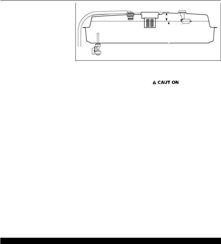
1-3/8 inch [3.5 cm or 35 mm] |
|||
|
||||
GROUNDING |
|
|
|
|
1. Use the ground terminal and |
|
|
|
|
|
|
|
|
|
wing nut on the generator frame |
|
|
|
|
to connect the unit to a suitable |
|
|
|
|
ground source. Securely fasten |
|
|
|
|
the end terminal of the ground |
|
|
|
|
wire to the ground terminal on |
|
|
|
|
the generators frame. Tighten the |
|
|
Gasoline Fill Level |
|
washer and wing nut on top of the |
|
|
||
ground wire end terminal. |
|
|
|
|
Figure 1
2.The ground wire should be made
of #8 gauge wire. Do not use wire |
FUELING AND REFUELING |
6. |
After each start up, allow the |
|||||||||||||
with a higher gauge number. |
(SEE FIGURE 1) |
|
|
|
engine to run for 2-3 minutes with |
|||||||||||
Higher gauge numbers indicate |
1. |
Shut-off engine and wait 2 minutes |
|
|
no load. |
|
||||||||||
thinner wire, which may not |
|
|
before filling fuel tank. |
|
|
|
|
|
Engine speed is |
|||||||
|
|
|
|
|
|
|
||||||||||
provide an adequate ground path. |
2. |
|
Remove fuel cap and fill fuel tank |
|
|
|
|
|
preset to provide |
|||||||
|
|
|
|
|
|
|||||||||||
3. The other end of the ground wire |
|
proper output voltage. Never attempt |
||||||||||||||
|
|
to bottom of metal filler neck; |
||||||||||||||
|
|
to modify or adjust engine speed or |
||||||||||||||
must be securely fastened to an |
|
|
about 1-3/8 inch [3.5 cm or 35 mm] |
|||||||||||||
|
|
output voltage. |
|
|||||||||||||
approved ground source. |
|
|
|
|
from top of filler neck opening. |
|
||||||||||
|
|
|
|
|
|
|
|
|
|
|
||||||
The following are ground sources |
3. |
Do not overfill fuel tank. Overfilling |
ENGINE BREAK-IN |
|
||||||||||||
approved by the National Electric |
|
|
may damage roll-over valve and |
After initial start-up, the engine |
||||||||||||
Code. Other ground sources may be |
|
|
carbon canister. |
|
should be broken in according to the |
|||||||||||
acceptable. Refer to the National |
4. |
|
Reinstall fuel cap; make sure to |
manufacturer's instructions. Refer to the |
||||||||||||
Electric Code and local regulations for |
|
engine manual for the proper break-in |
||||||||||||||
|
|
rotate cap clockwise unit it stops. |
||||||||||||||
further ground source information. If |
|
|
procedure. |
|
||||||||||||
|
|
|
|
|
|
|||||||||||
not sure of regulations or procedures, |
STARTING |
|
SHUT-OFF |
|
||||||||||||
obtain assistance from a qualified |
|
|
||||||||||||||
1. |
|
Remove all electrical loads from the |
|
|||||||||||||
(licensed or certified) electrical |
|
|
|
1. |
Shut off and remove all electrical |
|||||||||||
|
|
|
|
generators. |
|
|||||||||||
technician. |
|
|
|
|
|
|
|
|
load devices from the generator. |
|||||||
|
|
|
2. |
|
Rotate fuel petcock valve lever, |
|
|
|||||||||
a. An underground water pipe at |
|
2. |
Allow the engine to run for 2-3 |
|||||||||||||
|
|
located on underside of fuel tank, |
||||||||||||||
least ten feet in length |
|
|
|
|
|
|
minutes with no electrical loads. |
|||||||||
|
|
|
|
to the vertical position to open |
|
|
||||||||||
b. A non-corrosive underground |
|
|
3. |
Flip the engine toggle switch (on |
||||||||||||
|
|
valve. |
|
|||||||||||||
pipe at least eight feet in length |
|
|
|
|||||||||||||
3. |
Flip engine toggle switch (on |
|
|
control panel) to the OFF position. |
||||||||||||
and 3/4 inch diameter |
|
|
|
|
||||||||||||
|
|
4. |
Verify that the generator has |
|||||||||||||
c. A steel or iron underground rod |
|
|
control panel) to the ON position. |
|||||||||||||
at least eight feet in length and |
4. |
The engine is equipped with an |
|
|
completely stopped. |
|
||||||||||
5. |
Rotate fuel petcock valve lever, |
|||||||||||||||
5/8 inch diameter |
|
|
|
|
automatic choke. However, the |
|||||||||||
d. A non-ferrous rod at least |
|
|
choke mechanism has a manual |
|
|
located on underside of fuel tank, |
||||||||||
eight feet in length, 1/2 inch |
|
|
override feature for extreme cold |
|
|
to the horizontal position to close |
||||||||||
in diameter, and approved for |
|
|
weather starting. For extreme cold |
|
|
valve. |
|
|||||||||
grounding purposes |
|
|
|
|
weather starting, pull choke wire; |
6. |
Allow the unit to cool before |
|||||||||
Any rod or pipe used for grounding |
|
|
after engine warms, push choke in |
|
|
installing any covers. |
|
|||||||||
must be driven to eight feet deep or |
|
|
to it's normal operating position. |
|
|
|
|
|
|
|
||||||
|
|
|
|
|
|
|
|
|
|
|
|
|||||
buried in the deepest possible trench. |
5. |
Pull the starter rope with a brisk, |
|
|
|
|
|
|
|
|||||||
|
|
|
|
|
|
smooth motion. |
|
|
|
|
|
|
|
|
||
|
|
|
|
|
|
|
|
|
|
|||||||
|
|
|
TABLE 1 - ESTIMATED POWER USAGE (WATTS) |
|
|
|
|
|
||||||||
LOAD DEVICE |
WATTS |
|
LOAD DEVICE |
WATTS |
LOAD DEVICE |
WATTS |
LOAD DEVICE |
WATTS |
||||||||
Air conditioner |
2000-3000 |
|
Electric drill |
|
|
500-1000 |
|
Radio |
50-200 |
|
Toaster |
900-1700 |
||||
|
|
|
|
|
||||||||||||
|
|
|
(large) |
|
|
|
|
|
|
|
|
|
|
|
|
|
Automatic |
150-1500 |
|
Fan |
|
|
40-200 |
|
Refrigerator |
190-2000 |
Vacuum cleaner |
200-300 |
|||||
washer |
|
|
|
|
|
|
|
|
|
|
|
|
|
|
|
|
Brooder |
100+ |
|
Freezer |
|
|
300-500 |
|
Skillet |
1200 |
|
Water pump |
1000-3000 |
||||
Clothes dryer |
5000-10,000 |
|
Hot plate |
|
|
330-1100 |
|
Space heater |
600-4800 |
Water heater |
1000-5000 |
|||||
Coffee maker |
400-700 |
|
Iron |
|
|
500-1500 |
|
Sump pump |
400-3000 |
Small hand saw |
1000-2000 |
|||||
Electric drill |
225-1000 |
|
Light bulb |
|
|
AS RATED |
|
Television |
200-500 |
Large hand saw |
1500-2500 |
|||||
(small) |
|
|
|
|
|
|
|
|
|
|
|
|
|
|
|
|
|
|
|
|
|
|
|
|
|
|
|
|
|
|
|
|
|
www.chpower.com
4

|
|
|
|
|
|
|
|
|
|
|
GN5060, GN6575 |
|||
Pre-Operation (Continued) |
3. |
The 120 volt receptacles are rated |
manuals and product tags to determine |
|||||||||||
AUTO-IDLE CONTROL (IF EQUIPPED) |
|
for 20 amps and may be used in any |
the wattage of all electrical load |
|||||||||||
|
combination of 120 volt loads and |
devices. |
|
|||||||||||
Some units have an auto-idle control |
|
|
||||||||||||
|
also with 240 volt loads through |
If actual watt ratings are not available, |
||||||||||||
that idles the engine when there is no |
|
the 240 volt receptacles. |
||||||||||||
|
the Power Usage Chart, see Table 1, may |
|||||||||||||
demand required of the generator. |
|
|
|
|
||||||||||
|
|
The 240 volt receptacles, found |
be used as a general guideline. |
|||||||||||
The control panel has an idle control |
|
|||||||||||||
|
on some generators, are rated for |
Remember that devices which generate |
||||||||||||
toggle switch to enable or disable this |
|
|||||||||||||
|
20 amps and may be used in any |
|||||||||||||
function. |
|
|
|
heat during operation such as heaters, |
||||||||||
|
|
|
combination of 240 volt loads and |
|||||||||||
1. |
Idle Control Switch - ON enables |
|
incandescent light bulbs, motors and |
|||||||||||
|
also with 120 volt loads through |
|||||||||||||
|
hair dryers have a higher power draw |
|||||||||||||
|
the auto-idle feature and the |
|
|
the 120 volt receptacles. |
||||||||||
|
|
|
than devices which generate little heat |
|||||||||||
|
engine will automatically idle when |
|
|
|||||||||||
|
The 120/240 volt twist lock |
during operation such as florescent |
||||||||||||
|
not under load. |
|
|
|
||||||||||
|
|
|
|
receptacle is rated for 20 amps and |
bulbs, radios, and clocks. |
|
||||||||
2. |
Idle Control Switch - OFF disables |
|
|
|||||||||||
|
may be used in any combination of |
Long power cords and extension cords |
||||||||||||
|
the auto-idle feature and the |
|
|
120 volt and 240 volt loads. |
||||||||||
|
|
|
also draw additional power. Keep cords |
|||||||||||
|
engine will run at full throttle. |
|
|
|
|
|||||||||
|
|
4. |
Individual receptacles should not |
at minimum possible length. |
|
|||||||||
LOW OIL SHUTDOWN |
|
|
||||||||||||
|
|
be loaded beyond the amperage |
Refer to Table 2 for maximum limits for |
|||||||||||
A low oil shutdown switch is provided |
|
rating. |
|
|||||||||||
|
|
lengths of extension cords. |
|
|||||||||||
to protect the engine and generator |
|
|
|
|
||||||||||
5. Total combined load through |
8. |
Circuit protection is provided by a |
||||||||||||
on most extended run models. When |
||||||||||||||
|
any combination of receptacle |
|||||||||||||
|
|
|
circuit breaker. The circuit breaker |
|||||||||||
engine oil level drops too low for |
|
|
|
|
||||||||||
|
|
must not exceed the rated load |
|
|
||||||||||
|
|
|
|
opens when the generator load |
||||||||||
proper engine operation, the low oil |
|
|
|
|||||||||||
|
limits of the generator. Refer to |
|
|
|||||||||||
|
|
|
exceeds its maximum capacity |
|||||||||||
shutdown switch causes the engine |
|
|
|
|
||||||||||
|
|
the identification plate on the |
|
|
||||||||||
|
|
|
|
or a short circuit occurs. If the |
||||||||||
to shut off. If oil level is low when |
|
|
|
|
||||||||||
|
|
generators for amp and wattage |
|
|
||||||||||
|
|
|
|
circuit breaker opens, perform the |
||||||||||
attempting to start the generator |
|
|
|
|
||||||||||
|
|
specifications. |
|
|
|
|||||||||
|
|
|
|
|
following procedures to correct the |
|||||||||
engine, the low oil level shutdown |
|
|
|
|
|
|||||||||
|
|
|
|
|
|
|||||||||
|
6. |
Always shut off and remove loads |
|
|
problem: |
|
||||||||
switch prevents the engine from |
|
|
|
|
||||||||||
|
|
before starting or shutting off the |
|
|
|
|
|
|
|
|||||
starting. If engine does not start, check |
|
|
|
a. Shut off and disconnect all |
||||||||||
|
generator engine. |
|
|
|
||||||||||
oil level. |
|
|
|
|
|
|
|
electrical loads. |
|
|||||
|
|
|
|
|
|
|
|
|
||||||
NOTE: It is important to keep the |
|
7. |
When plugging multiple electrical |
|
|
b. Attempt to determine the cause |
||||||||
generator unit on a level surface. The |
|
load devices into the generator |
|
|
|
of the electrical problem - |
||||||||
oil level shutdown switch can prevent |
|
receptacles, be sure to connect and |
|
|
|
overloading or short circuit. |
||||||||
the engine from starting even if oil level |
activate the highest power draw |
|
|
c. Do not use any devices that have |
||||||||||
item first. Allow the generator |
|
|
||||||||||||
is sufficient, when the generators unit is |
|
|
|
short circuits. Avoid overloading |
||||||||||
engine to stabilize, then connect |
|
|
|
|||||||||||
placed on an uneven surface. |
|
|
|
|
|
the generator. |
|
|||||||
|
|
and activate the next highest power |
|
|
|
|
||||||||
|
|
|
|
|
|
|
d. Press the circuit breaker |
|||||||
|
|
|
|
|
draw device. The smallest power |
|
|
|||||||
Operation |
|
|
|
|
|
|
pushbutton to reset the circuit |
|||||||
|
|
|
draw device should be connected to |
|
|
|
||||||||
|
|
|
|
|
|
breaker. |
|
|||||||
LOAD DEVICES |
|
|
|
the receptacle and activated last. |
|
|
|
|
||||||
|
|
|
|
|
|
|
|
Repeated cycling of |
||||||
1. |
All load devices and extension cords NOTE: Power draw can be calculated |
|
|
|
|
|
||||||||
|
|
|
|
|
the circuit |
|||||||||
|
should use three prong terminals. |
by multiplying volts and amps. The |
|
|
|
|
|
|||||||
|
breaker indicates a problem and |
|||||||||||||
|
Refer to Table 2 for extension cord |
resulting number is wattage. |
may cause damage to the generator |
|||||||||||
|
and cable size requirements. |
|
Never exceed the posted maximum |
or load devices. Do not operate the |
||||||||||
2. |
Allow the engine to run for 2-3 |
|
generatoreated cycling of the circuit |
|||||||||||
|
wattage for the generator or any |
|||||||||||||
|
breaker occurs. |
|
||||||||||||
|
minutes before applying any |
|
individual receptacle. Refer to owner's |
|
||||||||||
|
|
|
|
|
|
|
|
|
||||||
|
electrical loads. |
|
|
|
|
|
|
|
|
|
|
|
|
|
|
|
|
|
|
|
|
|
|
|
|
|
|
||
|
|
|
|
|
TABLE 2 - EXTENSION CORDS |
|
|
|
|
|
|
|
||
|
|
|
|
Maximum Recommended Lengths (in feet) |
|
|
|
|
|
|||||
|
Amps |
Watts 120 V |
Watts 240 V |
#8 Wire |
#10 Wire |
#12 Wire |
|
#14 Wire |
#16 Wire |
|||||
|
2.5 |
300 |
|
600 |
|
1000 |
600 |
|
375 |
250 |
||||
|
5 |
600 |
|
1200 |
|
500 |
300 |
|
200 |
125 |
||||
|
7.5 |
900 |
|
1800 |
|
350 |
200 |
|
125 |
100 |
||||
|
10 |
1200 |
|
2400 |
|
250 |
150 |
|
100 |
50 |
||||
|
15 |
1800 |
|
3600 |
|
150 |
100 |
|
65 |
|
||||
|
20 |
2400 |
|
4800 |
175 |
125 |
75 |
|
50 |
|
||||
|
|
|
|
|
|
|
|
|
|
|
|
|
||
|
25 |
3000 |
|
6000 |
150 |
100 |
60 |
|
|
|
|
|
||
|
30 |
3600 |
|
7200 |
125 |
65 |
|
|
|
|
|
|
|
|
|
40 |
4800 |
|
9600 |
90 |
|
|
|
|
|
|
|
|
|
|
|
|
|
|
|
|
|
|
|
|
|
|
||
|
|
|
|
|
|
|
|
|
|
|
|
www.chpower.com |
||
5

Operating Instructions and Parts Manual
Operation (Continued) |
Maintenance |
5. Slowly pull the starter cord, until |
||||||||
INSTALLATION FOR STAND-BY USE |
INFREQUENT USAGE |
|
resistance is felt. This indicates that |
|||||||
|
the piston is moving upward on the |
|||||||||
Precautions must be taken to prevent |
If the generator is used infrequently, |
|
||||||||
|
compression cycle, and the intake |
|||||||||
electrical back feeding into utility |
starting difficulty may occur. To help |
|
||||||||
|
and exhaust valves are closed. (The |
|||||||||
systems. This requires isolation of |
prevent this, the generators should be |
|
||||||||
|
piston pushes a small amount of |
|||||||||
the electrical system. To isolate the |
run for approximately 30 minutes per |
|
||||||||
|
air from the spark plug hole on |
|||||||||
electrical system, perform the following |
week. |
|
||||||||
|
compression.) |
|||||||||
procedures: |
|
|
|
|||||||
STORAGE |
6. Use of fuel stabilizers or anti- |
|||||||||
1. Turn off the main electrical system |
||||||||||
If the generator is not to be used for |
|
gumming agents in the fuel system |
||||||||
|
switch prior to connecting the |
|
||||||||
|
extended periods of time, the following |
|
can help prevent the build up of |
|||||||
|
generator. |
|
||||||||
|
pre-storage procedures should be |
|
gum and varnish. |
|||||||
2. In accordance with national and |
|
|||||||||
performed: |
Whenever the generator is stored, be |
|||||||||
|
local standards, a double throw |
|
|
|||||||
|
1. |
Make sure engine oil is filled to the |
sure that the fuel shut-off valve is in the |
|||||||
|
transfer switch must be installed in |
|||||||||
|
|
proper level. |
closed position. |
|||||||
|
the system. |
|
||||||||
|
2. |
Drain all fuel from the tank, lines, |
Refer to the engine manual that |
|||||||
|
|
|
Always shut off |
|||||||
|
|
|
|
carburetor and fuel valve. |
accompanies this unit for instructions |
|||||
|
|
|
main power prior to |
|
||||||
|
|
|
3. Remove the spark plug, and pour |
regarding maintenance of engine |
||||||
temporary connection of the generator |
||||||||||
components. |
||||||||||
to a building electrical system. |
|
approximately one teaspoon of oil |
||||||||
|
|
|
Installation of the |
|
into the spark plug hole. |
|
|
|
Never tamper with |
|
|
|
|
generator as a |
4. |
Pull the starter cord several times |
|
|
|
engine speed |
|
|
|
|
||||||||
|
|
|
|
|
|
|||||
|
|
|
||||||||
backup electrical source must be |
settings. Any governor adjustments |
|||||||||
|
to spread the oil throughout the |
|||||||||
performed by a qualified (licensed or |
|
should be made by qualified personnel |
||||||||
|
cylinder. |
|||||||||
certified) electrical technician. |
|
only. |
||||||||
|
|
|||||||||
www.chpower.com
6

GN5060, GN6575
Troubleshooting Chart
Symptom |
Possible Cause(s) |
Corrective Action |
||
Engine will not |
1. |
Run switch is set to "OFF". |
1. |
Set run switch to "ON". |
start |
2. |
Fuel valve is turned to "CLOSE". |
2. |
Turn fuel valve to "OPEN" position. |
|
3. |
Choke is open. |
3. |
Close the choke. |
|
4. |
Fuel tank is empty. |
4. |
Add gas. |
|
5. |
Engine is filled with |
5. |
Change the gas in the engine. |
|
|
contaminated or old gas |
6. |
Clean spark plug. |
|
6. |
Spark plug is dirty. |
||
|
7. |
Spark plug is broken. |
7. |
Replace spark plug. |
|
8. |
Unit is not on level surface. |
8. |
Move unit to a level surface to prevent low oil shutdown from |
|
|
|
|
triggering. |
|
9. |
Oil is low. |
9. |
Add or replace oil. |
Engine runs |
1. |
Main or secondary circuit |
1. |
Reset main or secondary circuit breaker(s). |
but there is no |
|
breaker(s) are tripped. |
|
|
electrical output |
2. |
Bad connecting of wires/cables. |
2. |
If you are using an extension cord, try a different one. |
|
3. |
Bad electrical device connected |
3. |
Try connecting a different device. |
|
|
to generator. |
|
|
Generator runs |
1. |
Generator is overloaded |
1. |
Turn off all electrical devices. Unplug all electrical devices. Turn |
but does not |
|
|
|
off generator. Wait several minutes. Restart generator. Try |
support all |
|
|
|
connecting fewer electrical loads to the generator. |
electrical devices |
2. |
Short in one of the connected |
2. |
Try disconnecting any faulty or short-circuited electrical loads. |
connected. |
|
devices. |
|
|
|
3. |
Air cleaner is dirty. |
3. |
Clean or replace air cleaner. |
No output |
1. |
Engine speed is too slow |
1. |
Adjust engine speed. |
voltage |
2. |
Open, shorted, or incorrect |
2. |
Referring to the wiring diagram, clean and reconnect all |
|
|
wiring |
|
wiring. |
|
3. |
Faulty capacitor |
3. |
Replace capacitor. |
|
4. |
Open or shorted field windings |
4. |
Test winding resistance, replace field winding if necessary. |
|
5. |
Open diodes |
5. |
Test diodes, replace if necessary. |
|
6. |
Circuit breaker tripped |
6. |
Reset circuit breaker. |
Low output |
1. |
Engine speed is too slow |
1. |
Adjust engine speed. |
voltage with no |
2. |
Open diodes |
2. |
Test diodes, replace if necessary. |
load |
3. |
Faulty capacitor |
3. |
Replace capacitor. |
|
4. |
Open or shorted field windings |
4. |
Test winding resistance, replace field winding if necessary. |
High output |
1. |
Faulty capacitor |
1. |
Replace capacitor. |
voltage with no |
2. |
Engine speed is too fast |
2. |
Adjust engine speed. |
load |
|
|
|
|
Low output |
1. |
Open diode |
1. |
Test diodes, replace if necessary. |
voltage under |
2. |
Engine speed too slow at full |
2. |
Adjust engine speed. |
load |
|
load |
3. |
Reduce the applied load. |
|
3. |
Excessive load applied |
|
|
Erratic output |
1. |
Unbalanced engine |
1. |
Refer to engine manual. |
voltage |
2. |
Dirty, corroded, or loose wiring |
2. |
Referring to the wiring diagram, clean and reconnect all |
|
|
connection |
|
wiring. |
|
3. |
Unstable load applied |
3. |
Remove all loads, then apply each one individually to |
|
|
|
|
determine which one is causing erratic function. |
Noisy operation |
1. |
Loose generator or engine bolt |
1. |
Tighten all mountings. |
|
2. |
Short circuit in generator field or |
2. |
Test winding resistance, replace field winding if necessary. |
|
|
load |
|
Test load devices for shorts. Replace defective load device. |
|
3. |
Faulty bearing |
3. |
Replace bearing. |
Auto-Idle does |
1. |
Damaged or disconnect wire in |
1. |
Repair or replace wiring. |
not work |
|
idle control circuit. |
|
|
|
2. |
Failed idle control circuit board. |
2. |
Replace idle control board. |
|
3. |
Failed current sensing coil. |
3. |
Replace current sensing coil. |
These diagnostic and repair procedures should be performed by an authorized service center.
www.chpower.com
7

Operating Instructions and Parts Manual
Service Record
Date |
Maintenance performed |
|
Repair components required |
|
|
|
|
|
|
|
|
|
|
|
|
|
|
|
|
|
|
|
|
|
|
|
|
|
|
|
|
|
|
|
|
|
|
|
|
|
|
|
|
|
|
|
|
|
|
|
|
|
|
|
|
|
|
|
|
|
|
|
|
|
|
|
|
|
|
|
|
|
|
|
|
|
|
|
|
|
|
|
|
|
|
|
|
|
|
|
|
|
|
|
|
|
|
|
|
|
|
|
|
|
|
|
|
|
|
|
|
|
|
|
|
|
|
|
|
|
|
|
|
|
|
|
|
|
|
|
|
|
|
|
|
|
|
|
|
|
|
|
|
|
|
|
|
|
|
|
|
|
|
|
|
|
|
|
|
|
|
|
|
|
|
|
|
|
|
|
|
|
|
|
|
|
|
|
|
|
|
|
|
|
|
|
|
|
|
|
|
|
|
|
|
|
|
|
|
|
|
|
|
|
www.chpower.com
8
GN5060, GN6575
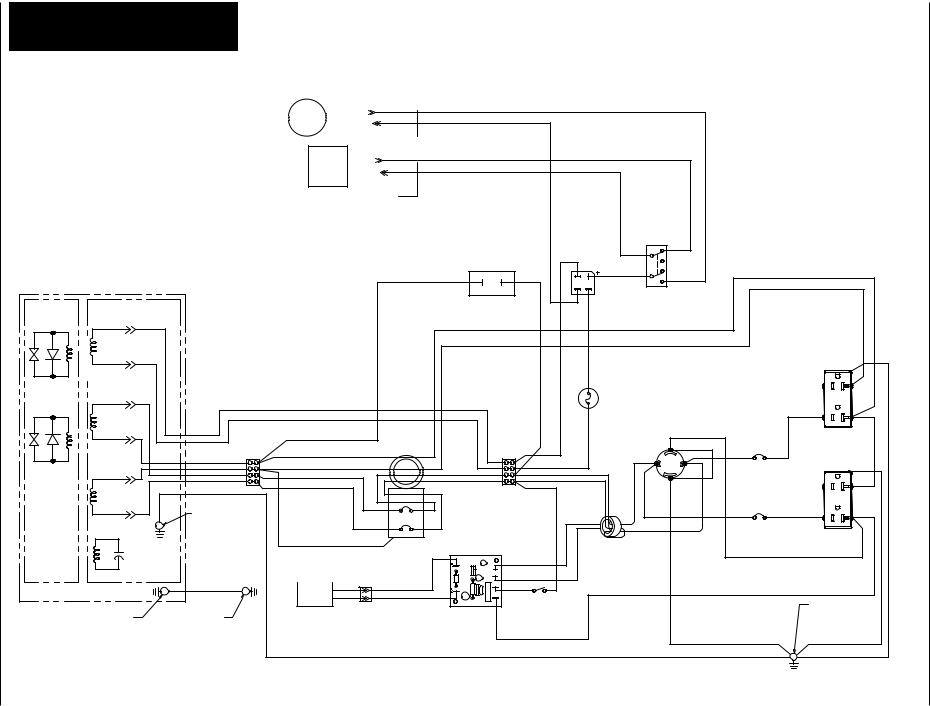
Stranded Copper |
|
|
|
|
|
|
|
|
|
|
|
|
|
|
|
|
|
|
|
|
|
|
|
|
|
|
Wire Lead |
Wire Number |
|
|
|
|
|
|
|
|
|
|
|
|
|
|
|
|
|
|
|
|
|
|
|
|
|
Specifications |
per Schematic |
|
|
|
|
|
|
|
|
|
|
|
|
|
|
|
|
|
|
|
|
|
|
|
|
|
|
|
|
|
|
|
|
|
|
|
|
|
|
|
|
|
|
|
|
|
|
|
|
|
|
|
|
8 AWG, SAE J1128, |
Ground Wire at |
|
|
|
|
|
|
|
|
ENGINE |
|
|
|
|
|
|
|
|
|
|
||||||
GPTI |
Generator Frame |
|
|
|
|
|
|
|
|
|
|
|
|
|
|
|
|
|
|
|
|
|
|
|
|
|
|
|
|
|
|
|
|
|
|
CARBURETOR |
|
||||||||||||||||
12 AWG, UL 1015/ |
11, 12, 13, 14, 15, |
|
|
|
|
|
|
|
|
|||||||||||||||||
|
|
|
|
|
|
|
SOLENOID |
|
||||||||||||||||||
|
|
|||||||||||||||||||||||||
UL 1230 |
16, 17, 18, 19, 20, |
|
|
|
|
|
|
|
|
|
|
|
|
|
|
|
|
|
41 |
|
||||||
|
|
|
|
|
|
|
|
|
|
|
|
|
|
|
|
|
||||||||||
|
25, 26, 27, 28, 29, |
|
|
39 |
|
|||||||||||||||||||||
|
|
|
|
|
|
|
|
|
|
|
|
|
|
|
|
|
|
|
|
|
|
|
|
|
|
|
|
30, 31, 34, 35, 45 |
|
|
|
|
|
|
|
|
|
|
|
|
|
|
|
|
|
|
|
|
|
|
|
|
|
|
|
|
|
|
|
|
|
|
|
|
|
|
|
|
|
|
|
|
|
|
|
|
|
|
||
|
|
|
|
|
|
|
|
|
|
|
|
|
|
|
|
|
|
|
|
|
|
|
|
|
|
|
16 AWG, SAE |
23, 24, 28, 32, 33, |
|
|
|
|
|
|
|
|
|
|
|
|
|
|
|
|
|
|
|
42 |
|
||||
|
|
|
|
|||||||||||||||||||||||
|
|
|||||||||||||||||||||||||
J1128, Type TXL |
36, 37, 38, 39, 40, |
|
|
|
|
40 |
|
|||||||||||||||||||
|
|
|
||||||||||||||||||||||||
Ins. |
42, 43, 44, 46 |
|
|
|
|
|
|
|
|
IGNITION MODULE |
||||||||||||||||
|
|
|
|
|
|
|
|
|
|
|||||||||||||||||
|
|
|
|
|
|
|
|
|
|
|
|
|
|
|
|
|
|
|
|
|
|
|
|
|
|
|
ROTOR |
STATOR |
|
|
|
|
|
|
|
|
A |
WINDING |
|
|
|
|
|
|
|
|
|
|
|
|
|
|
|
|
U |
|
|
|
|
|
|
|
|
12V |
|
L2 |
|
|
|
|
|
|
|
|
|
|
ORANGE |
|
|
|
|
MAIN WINDING |
|
ORANGE |
|
|
|
||
|
120V |
|
N |
|
|
|
|
|
|
|
|
|
|
|
WHITE |
|
|
|
|
|
|
|
TB1 43 11 |
WHITE |
|
|
|
|
|
N |
|
12 |
BLUE |
|
|
|
|
|
|
13 |
BROWN |
|
|
|
|
|
|
|
|
14 |
BLACK |
|
|
|
MAIN WINDING |
|
GREEN |
|
|
|
||
|
120V |
|
L1 |
|
|
13 |
|
15 |
|
|
|
|
30 |
GROUND SCREW IN |
|
|
|
|
EXCITATION |
|
|
|
ALTERNATOR HOUSING |
14 |
|
16 |
|
WINDING |
|
|
|
|
|
|
|
|
CAPACITOR |
|
|
|
WHITE GFCI WIRE |
CB1 |
|
|
|
|
|
|
|
|
|
2-POLE |
32 |
|
|
|
|
|
|
|
GFCI |
|
|
|
|
|
|
|
|
CIRCUIT |
|
|
|
|
|
|
|
|
BREAKER |
|
ALTERNATOR |
|
|
BLACK |
32 |
BLACK |
|
||
|
|
|
33 |
BLACK |
33 |
|||
|
GROUND SCREW AT |
|
|
GROUND SCREW AT |
IDLE CONTROL |
|
|
|
|
ALTERNATOR HOUSING |
|
|
GENERATOR FRAME |
SOLENOID |
|
|
|
|
|
|
|
|
|
GREEN |
|
|
|
XILLIARY |
|
|
|
|
|
|
|
YELLOW
YELLOW / WHITE
BLACK
PINK
|
|
|
|
|
|
|
40 |
42 |
|
|
|
|
|
|
|
|
|
|
|
HOUR METER |
|
|
37 |
RECTIFIER |
RED |
|
|
||
43 |
|
44 |
BLACK |
|
|
41 |
|
||
|
|
38 |
38 |
|
|||||
|
|
|
|
|
|
AC |
ENGINE |
|
|
|
|
|
|
|
39 |
46 |
|
||
|
|
|
|
|
CONTROL |
|
|||
|
|
|
|
|
|
|
SWITCH |
|
|
|
|
|
|
|
|
|
|
|
WHITE |
|
|
|
|
|
|
|
|
|
BLUE |
|
|
|
|
|
|
46 |
|
|
|
|
|
|
|
|
|
FUSE - 15A |
|
|
|
|
|
|
|
|
ORANGE |
36 |
|
|
|
|
|
|
|
44 |
|
RECEPTACLE |
|
|
|
|
|
|
|
|
|
|
120 / 240 VOLT |
25 |
WHITE |
|
|
|
|
|
|
|
|
||
|
|
TB2 |
37 |
|
|
ORANGE |
NEMA L15-30R |
28 |
|
|
|
|
|
17 |
|
20 |
|||
|
|
|
|
|
|
|
|||
BROWN |
|
|
|
36 |
|
BROWN |
|
|
18 |
15 |
|
|
17 |
|
|
|
|||
|
|
|
19 |
|
28 |
||||
|
16 |
|
|
18 |
|
|
|
||
BLACK |
|
|
|
BLACK |
|
45 |
|
||
|
|
23 |
BLACK |
|
BROWN |
|
|||
|
|
|
|
|
|
|
|||
|
|
|
|
|
|
|
|
||
|
|
|
|
|
|
|
|
|
|
|
|
|
|
|
|
|
|
|
BROWN |
|
|
|
|
|
|
|
BLACK |
|
|
|
|
|
|
|
|
CURRENT SENSING COIL |
|
|
|
|
|
|
|
|
|
BLACK WIRE HAS (2) |
|
|
|
|
TR2 |
|
|
|
|
LOOPS THROUGH COIL |
|
|
|
|
|
|
|
|
BROWN WIRE HAS (1) |
|
|
||
|
TR1 |
|
|
|
|
|
|
||
|
|
|
|
|
LOOP THROUGH COIL |
|
|
||
|
AC1 |
BLACK 24 |
|
|
|
|
|||
|
|
|
|
|
|
|
|||
|
AC2 |
|
IDLE CONTROL |
|
|
|
|
||
IDLE CONTROL |
|
|
SWITCH |
|
|
|
|
|
|
|
|
|
|
|
|
|
|
|
|
CIRCUIT BOARD |
|
|
|
|
|
|
|
|
|
|
|
WHITE |
|
|
|
|
|
|
|
|
|
26 |
|
|
|
|
|
|
|
|
|
|
|
|
|
31 |
|
|
|
|
|
12 |
|
|
|
|
34 |
11 |
|
|
|
|
|
|
|
||
|
|
BLACK |
|
RECEPTACLE |
|
27 |
|
|
|
|
|
||
|
|
|
|
20A DUPLEX |
|
|
20 |
34 |
|
|
|
|
|
|
CB2 |
|
|
|
|
29 |
|
20A |
|
|
|
|
|
|
|
|
|
|
|
|
|
CIRCUIT |
|
|
|
|
27 |
BREAKER |
|
|
|
|
||
|
|
|
|
|
||
19 |
35 |
|
|
35 |
|
26 |
|
CB3 |
|
|
|
25 |
|
|
|
|
|
|
||
|
20A |
|
|
20A DUPLEX |
|
|
|
CIRCUIT |
|
|
RECEPTACLE |
|
|
BREAKER |
|
|
|
|
|
|
|
|
|
|
GROUND SCREW AT |
|
|
|
|
|
|
CONTROL PANEL |
|
|
|
GREEN |
45 |
29 |
GREEN |
|
|
|
|
|
|
|
||
|
GREEN |
|
|
GREEN |
|
|
|
|
30 |
31 |
|
|
|
www.chpower.com
9
GREEN
Figure 2 - Wiring Diagram

Operating Instructions and Parts Manual
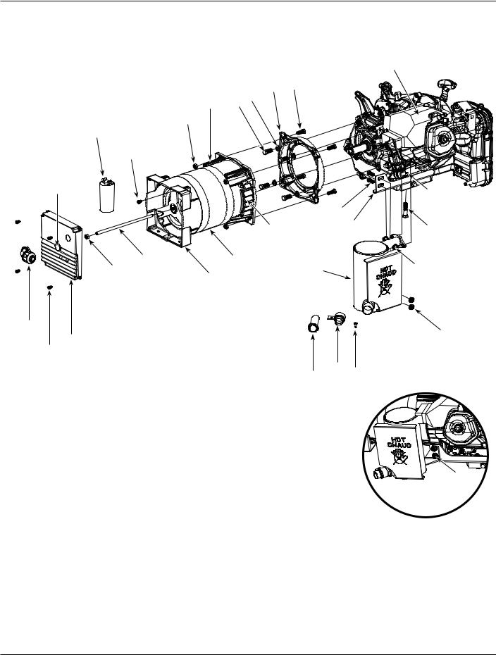
Generator Assembly
27
32
28
26
2
25
23 22
14
|
19 |
11 |
|
18 |
|
|
|
|
14 |
12 |
|
13 |
16 |
|
|
|
|
24 |
17 |
|
|
|
15
9
10
30
4  3
3
8
29
1
31
20
21
7
6
5
Figure 3
www.chpower.com
10
GN5060, GN6575
For replacement parts or technical assistance, call 1-800-803-1436
Please provide following information: |
Address parts correspondence to: |
- Model number |
Campbell Hausfeld |
- Serial number (if any) |
Attn: Customer Service |
- Part description and number as shown in parts list |
100 Mundy Memorial Dr. |
|
Mt. Juliet, TN 37122 USA |
Replacement Parts List
Ref. |
|
|
|
No. |
Description |
Part Number |
Qty. |
1 |
Generator Frame |
GN051081SJ |
1 |
2 |
Honda Engine and Sincro Alternator Assembly |
See Page 12 |
1 |
3 |
1/4 inch ID Fuel Hose, 8-1/4 inch L, Carb. to Petcock (GN5060 Only) |
|
1 |
4 |
3/8 inch Constant tension hose clamp (GN5060 Only) |
MJ111006AV |
2 |
5 |
Hex Bolt, 3/8 - 16 UNC X 3 inch L |
|
1 |
6 |
Fender Washer, 3/8 inch |
|
3 |
7 |
ISO Mount Assembly |
PM004290AV |
3 |
8 |
Hex Nut, 3/8 - 16 UNC |
|
2 |
9 |
Hex Bolt, 3/8 - 16 UNC X 2-1/2 inch L |
|
1 |
10 |
Hex Bolt, M8 - 1.25 X 70 |
|
1 |
11 |
ISO Mount Spacer |
GN051065AV |
1 |
12 |
Ground Cable, 8 AWG SAE |
GN052305AV |
1 |
13 |
Hex Bolt, 1/4 - 20 UNC X 3/4 inch L |
|
1 |
14 |
Flange Nut, 1/4 - 20 UNC |
|
7 |
15 |
Hex Bolt, 5/16 - 18 UNC X 1-1/4 inch L |
|
1 |
16 |
Star Washer - 5/16 inch Internal/External Tooth |
|
1 |
17 |
Flange Nut, 5/16 - 18 UNC |
|
1 |
18 |
Flat Washer - 0.344 X 0.688 X 0.065 |
|
2 |
19 |
Wing Nut, 5/16 - 18 UNC |
|
1 |
20 |
600cc Carbon Canister |
GN051031AV |
1 |
21 |
Carriage Bolt - 1/4 - 20 UNC X 3/4 inch L |
|
2 |
22 |
Control Panel Assembly (Includes ALL parts listed on page 14, plus all wiring and conduit) |
GN051111SJ |
1 |
23 |
Pan Head Screw, 1/4 - 20 UNC X 3/4 inch L |
|
6 |
24 |
Conduit, 0.62 inch ID, 6 inch L |
|
1 |
25 |
Conduit, 0.62 inch ID, 18 inch L |
|
1 |
26 |
Fuel Tank |
GN051030AV |
1 |
27 |
Hex Bolt, 1/4 - 20 UNC X 1 inch L |
|
4 |
28 |
Fender Washer - 1/4 inch |
|
4 |
29 |
Grommet - 0.688 X 0.563 ID Hole X 0.063 Groove |
|
1 |
30 |
1/4 inch ID Fuel Hose, 35 inch L (Tank to Carbon Canister) |
|
1 |
31 |
1/2 inch ID Fuel Hose, 4 inch L (Carbon Canister to Engine) |
|
1 |
32 |
Roll-over Valve |
GN051032AV |
1 |
|
Warning Decal - Frame |
DK667841AV |
1 |
|
Warning Decal (CPSC) - Fuel Tank |
DK667848AV |
1 |
|
Warning Decal (Earth Ground) - Frame |
DK667849AV |
1 |
|
Warning Decal (Fueling Process) - Fuel Tank |
DK667850AV |
1 |
|
Warning Decal (Not sold in California) - Fuel Tank |
DK667851AV |
1 |
|
Warning Decal (Spark Warning) - Frame |
DK667155AV |
1 |
|
Warning Decal (EPA Certification) - Frame |
DK667500AV |
1 |
Standard hardware item, available at local hardware stores
www.chpower.com
11
Operating Instructions and Parts Manual
Alternator Assembly
|
|
|
|
|
1 |
|
|
3 |
4 |
|
|
14 |
6 |
7 |
|
|
|
5 |
|
|
|
|
|
10 |
|
|
|
|
|
8 |
|
|
|
|
|
13 |
|
|
|
|
23 |
|
|
|
|
|
|
|
|
|
|
20 |
|
|
|
15 |
|
18 |
22 |
|
|
|
|
||
11 |
2 |
|
|
|
19 |
5 |
|
|
17 |
|
|
9 |
|
|
|
|
|
16
21
12
8
24 25 26
21
Assembled muffler detail showing flange hex nut position.
Figure 4
www.chpower.com
12

GN5060, GN6575
For replacement parts or technical assistance, call 1-800-803-1436
Please provide following information: |
Address parts correspondence to: |
- Model number |
Campbell Hausfeld |
- Serial number (if any) |
Attn: Customer Service |
- Part description and number as shown in parts list |
100 Mundy Memorial Dr. |
|
Mt. Juliet, TN 37122 USA |
Replacement Parts List
Ref. |
|
|
|
|
No. |
|
Description |
Part Number |
Qty. |
1 |
|
Honda GX390 Low Profile Engine |
GN060001AV |
1 |
|
|
Honda GX270 Low Profile Engine |
GN060000AV |
1 |
2 |
● |
Sincro Alternator - 6.8 kVA, 60Hz |
GN051001SJ |
1 |
|
■ |
Sincro Alternator - 5.2 kVA, 60Hz |
GN051000SJ |
1 |
3 |
■ ● |
Sincro Engine Adapter |
Not Available |
1 |
4 |
■ ● |
Hex Bolt, M8 x 25mm |
|
4 |
|
|
|
|
|
5 |
■ ● |
M8 NyLock Nut |
|
5 |
6 |
|
Hex Bolt, 3/8 - 16UNC X 1.00L |
|
4 |
7 |
|
3/8 inch Lock Washer |
|
4 |
8 |
■ ● |
Screw, Pan Head, M5 X 10mm |
|
5 |
|
|
|
|
|
9 |
■ ● |
Sincro Rear Shield |
GN051016AV |
1 |
10 |
■ ● |
Capacitor - 35mf, 450V |
GW001016SV |
1 |
11 |
● |
Sincro Threaded Rod (6.8 kVA Alt.) |
GN051008AV |
1 |
|
■ |
Sincro Threaded Rod (5.2 kVA Alt.) |
GN051025AV |
1 |
12 |
■ ● |
Sincro Rear Cover Kit |
GN051002SJ |
1 |
13 |
■ ● |
Sincro Round Hole Plug |
GN051009AV |
1 |
14 |
■ ● |
Sincro LH Louver |
GN051018AV |
1 |
15 |
■ ● |
Sincro RH Louver |
GN051017AV |
1 |
16 |
|
Elbow ConnectorHEYCO 8425 |
GN051096AV |
1 |
17 |
|
Honda Muffler |
▲ |
1 |
18 |
|
Muffler Bracket - Honda GX390 Engine |
GN051012KK |
1 |
|
|
Muffler Bracket - Honda GX270 Engine |
GN051011KK |
1 |
19 |
|
Flange Hex Nut, M8 |
|
2 |
20 |
|
Hex Bolt- 5/16 - 18 UNC X 0.75 L |
|
2 |
|
|
|
|
|
21 |
|
Flange Hex Nut, 5/16 - 18 UNC |
|
2 |
22 |
|
Hex Bolt, 3/8 - 16 UNC x 1-3/4 inch L |
|
1 |
23 |
|
Flange Hex Nut, 3/8 -16 UNC |
|
1 |
24 |
|
USDA Screen |
GN051013AV ▲ |
1 |
25 |
|
Clamp, USDA Screen |
GN051014AD ▲ |
1 |
26 |
|
Pan Head Self Tapping Screw (Muffler Clamp) |
GN051015AV ▲ |
1 |
|
|
|
||
REPLACEMENT PARTS KITS |
|
|
||
|
|
|
|
|
▲ |
Honda Muffler Kit |
GN051010SJ |
|
|
SYMBOLS DEFINED
■Included with GN051000SJ - Sincro Alternator (5.2 kVA)
●Included with GN051001SJ - Sincro Alternator (6.8 kVA)
Standard hardware item, available at local hardware stores
www.chpower.com
13
Operating Instructions and Parts Manual
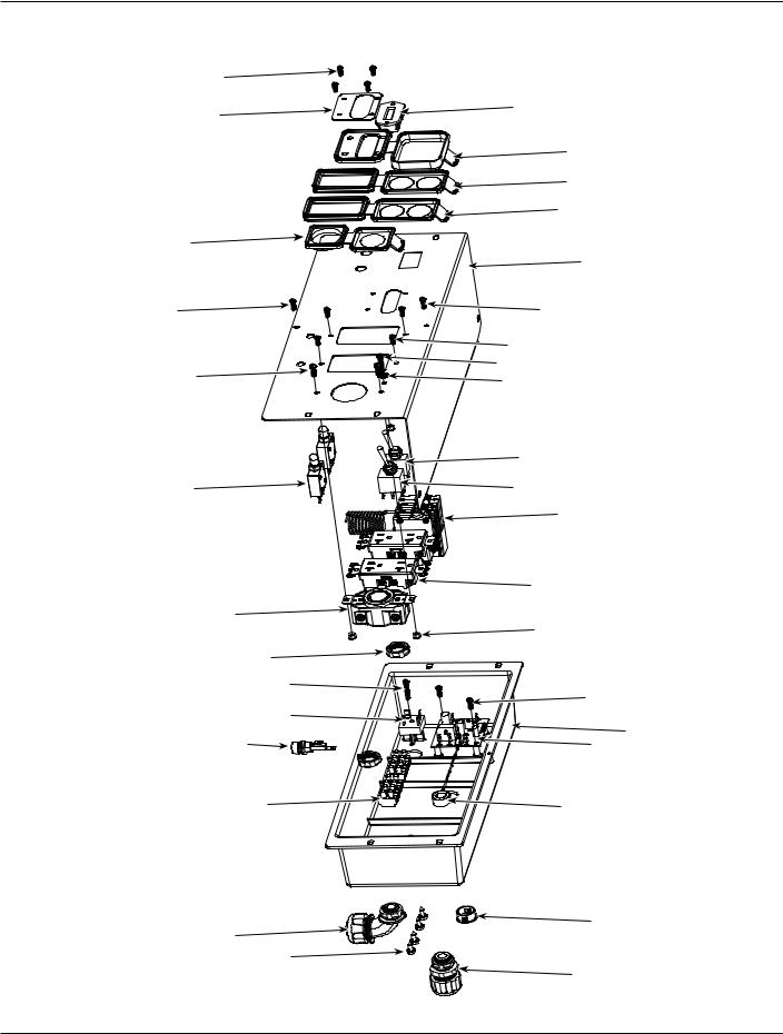
Control Panel Assembly
5 |
|
|
4 |
12 |
|
|
3 |
|
|
6 |
|
|
6 |
|
8 |
|
|
|
1 |
|
26 |
26 |
|
|
5 |
|
10 |
28 |
|
29 |
|
|
|
14 |
|
13 |
15 |
|
|
2 |
|
|
7 |
|
9 |
|
|
|
11 |
|
22 |
|
|
18 |
26 |
|
17 |
|
|
30 |
25 |
16 |
19 |
27 |
|
21 |
24 |
|
20 |
|
23 |
Figure 5
www.chpower.com
14

GN5060, GN6575
For replacement parts or technical assistance, call 1-800-803-1436
Please provide following information: |
Address parts correspondence to: |
- Model number |
Campbell Hausfeld |
- Serial number (if any) |
Attn: Customer Service |
- Part description and number as shown in parts list |
100 Mundy Memorial Dr. |
|
Mt. Juliet, TN 37122 USA |
Replacement Parts List
Ref. |
|
|
|
No. |
Description |
Part Number |
Qty. |
1 |
Control Panel |
GN051093AD |
1 |
2 |
GFCI Circuit Breaker |
GN051042AV |
1 |
3 |
Cover, GFCI Circuit Breaker |
GN051022AV |
1 |
4 |
GFCI Cover PlatePainted |
GN051024KK |
1 |
|
|
|
|
5 |
Pan Head Screw, #6 - 32 X 3/8 inch L |
|
8 |
6 |
Cover, Duplex Receptacle |
GN051021AV |
2 |
7 |
Duplex Receptacle120V, 20 Amp |
GN003403AV |
2 |
8 |
Cover, Twist Lock Receptacle |
GN051020AV |
1 |
|
|
|
|
9 |
Twistlock Receptacle, 125 - 250V, 30 Amp |
GW004255AV |
1 |
10 |
Pan Head Screw, #8 - 32 X 1/2 inch L |
|
3 |
11 |
Nylock Nut, #8 - 32 |
|
3 |
12 |
Digital Hour Meter |
GN051094AV |
1 |
13 |
Thermal Circuit Protector - Pushbutton |
GN051041AV |
2 |
14 |
Engine Run-Stop Switch |
GW004258AV |
1 |
15 |
Idle Control Switch |
PM351124AV |
1 |
16 |
Rear Control Panel Cover |
GN051023AV |
1 |
17 |
Bridge Rectifier, 200V, 15 Amp |
GN006651AV |
1 |
18 |
Pan Head Screw, 8 - 18 HiLo X 1 inch L |
|
1 |
19 |
Terminal Block |
GN051099AV |
2 |
20 |
Tapping Screw, #10 X 1/2 inch L |
|
4 |
|
|
|
|
21 |
Elbow ConnectorHeyco 8425 |
GN051096AV |
1 |
22 |
Connector Nut |
GN051097AV |
2 |
23 |
Straight Connector - Heyco 8402 |
GN051095AV |
1 |
24 |
Control Panel Hole Plug, 7/8 inch ID |
MJ106807AV |
1 |
|
|
|
|
25 |
Idle Control Circuit Board |
GN051070AV |
1 |
26 |
Pan Head Screw, #8 - HiLo X 1/2 inch L |
|
4 |
27 |
Idle Control Current Sensing Coil |
GN051075AV |
1 |
28 |
Pan Head Screw, #8-32 X 3/4 inch L |
|
1 |
29 |
#8 Lock Washer, Internal/External Tooth |
|
1 |
30 |
Fuse Holder |
HV010201AV |
1 |
|
Fuse, 1-1/4 inch x 1/4 inch, 15 Amp (not shown) |
|
1 |
Standard hardware item, available at local hardware stores
www.chpower.com
15
 Loading...