


See Warranty on page 12 for important information about commercial use of this product.
Operating Instructions and Parts Manual |
HL540200 |
|
|
Please read and save these instructions. Read carefully before attempting to assemble, install, operate or maintain the product described. Protect yourself and others by observing all safety information. Failure to comply with instructions could result in personal injury and/or property damage! Retain instructions for future reference.
Oil-Lubricated
Compressors
Description
This oil-lubricated compressor is designed for do-it-yourselfers with a variety of home and automotive jobs. These compressors power spray guns, impact wrenches and other tools. Compressed air from this unit will contain moisture. Install a water filter or air dryer if application requires dry air.
Unpacking
After unpacking the unit, inspect carefully for any damage that may have occurred during transit. Make sure to tighten fittings, bolts, etc., before putting unit into service. In case of questions, damaged or missing parts, please call 1-800-543-6400 for customer assistance. Have the serial number, model number, and parts list (with missing parts circled) before calling.
Do not return
STOP! the product to the retailer!
Do not operate unit if damaged during
shipping, handling or use. Damage may result in bursting and cause injury or property damage.
Read & Follow All Instructions
Save These Instructions
Do Not Discard
Record the Model No., Serial No. and date of purchase located on the base below the pump in the space below.
Model No. |
HL540200 |
Serial No. |
____________________ |
Date of purchase _________________
Retain these numbers for future reference.
Safety Guidelines
This manual contains information that is very important to know and understand. This information is provided for SAFETY and to PREVENT EQUIPMENT PROBLEMS. To help
recognize this information, observe the following symbols.
Danger indicates an imminently
hazardous situation which, if not avoided, WILL result in death or serious injury.
Warning indicates a potentially
hazardous situation which, if not avoided, COULD result in death or serious injury.
Breathable Air Warning
This compressor/pump is not equipped and should not be used “as is” to supply breathing quality air. For any application of air for human consumption, the air compressor/pump will need to be fitted with suitable in-line safety and alarm equipment. This additional equipment is necessary to properly filter
and purify the air to meet minimal specifications for Grade D breathing as described in Compressed Gas Association Commodity Specification
G 7.1 - 1966, OSHA 29 CFR 1910. 134, and/or Canadian Standards Associations (CSA).
DISCLAIMER OF WARRANTIES In the event the compressor is
used for the purpose of breathing air application and proper in-line safety and alarm equipment is not simultaneously used, existing warranties shall be voided, and the manufacturer disclaims any liability whatsoever for any loss, personal injury or damage.
Caution indicates a potentially
hazardous situation which, if not avoided, MAY result in minor or moderate injury.
Notice indicates important
information, that if not followed, may cause damage to equipment.
NOTE: Information that requires special attention.
REMINDER: Keep your dated proof of purchase for warranty purposes! Attach it to this manual or file it for safekeeping.
© 2010 Campbell Hausfeld/Scott Fetzer |
For parts, product & service information, |
IN620501AV 5/10 |
|
visit www.chpower.com |
|
Operating Instructions and Parts Manual
General Safety Information |
7. Before each use, inspect compressed |
12. Tanks rust from moisture build-up, |
||||||||||||||||||
California proposition 65 |
|
|
|
air system and electrical components |
|
which weakens the tank. Make sure |
||||||||||||||
|
|
|
for signs of damage, deterioration, |
|
to drain tank regularly and inspect |
|||||||||||||||
|
|
|
This product or its |
|
|
|||||||||||||||
|
|
|
|
weakness or leakage. Repair or |
|
periodically for unsafe conditions |
||||||||||||||
|
|
|
|
|
||||||||||||||||
|
|
|
power cord may |
|
|
|||||||||||||||
|
|
|
|
replace defective items before using. |
|
such as rust formation and corrosion. |
||||||||||||||
|
|
|
|
|
||||||||||||||||
contain chemicals, including lead, |
|
|
|
|
||||||||||||||||
|
|
|
|
|
|
|
|
|
|
|
|
|
|
|
|
|||||
known to the State of California to |
8. Check all fasteners at frequent |
13. Fast moving air will stir up dust |
||||||||||||||||||
cause cancer and birth defects or other |
|
intervals for proper tightness. |
|
and debris which may be harmful. |
||||||||||||||||
reproductive harm. Wash hands after |
|
|
||||||||||||||||||
|
|
|
|
Motors, |
|
|
|
|
|
Release air slowly when draining |
||||||||||
handling. |
|
|
|
|
|
|
|
|
|
|||||||||||
|
|
|
|
|
|
|||||||||||||||
|
|
|
You can |
|
|
|
|
|
|
|
electrical |
|
|
|
moisture or depressurizing the |
|||||
|
|
|
|
|
|
|
|
|
|
|||||||||||
|
|
|
|
|
|
equipment and controls can |
|
|
|
|
|
compressor system. |
||||||||
|
|
|
create |
|
|
|
|
|
|
|||||||||||
|
|
|
|
|
|
cause electrical arcs that |
|
|
|
|
|
|
|
|
|
|||||
|
|
|
|
|
|
|
|
|
|
|
|
|
|
|||||||
dust when you cut, sand, drill |
|
|
|
|
|
|
|
|
|
|
||||||||||
|
|
|
will ignite a flammable gas |
|
|
|
|
Spraying Precautions |
||||||||||||
or grind materials such as |
|
|
|
|
|
|||||||||||||||
|
|
|
or vapor. Never operate or repair in or |
|
|
|
Do not |
|
||||||||||||
wood, paint, metal, concrete, |
|
|
|
near a flammable gas or vapor. Never |
|
|
|
|
||||||||||||
cement, or other masonry. This dust |
|
|
|
spray |
|
|||||||||||||||
|
|
|
|
|||||||||||||||||
store flammable liquids or gases in the |
|
|
|
|
||||||||||||||||
often contains chemicals known to |
flammable materials in |
|
||||||||||||||||||
vicinity of the compressor. |
|
|||||||||||||||||||
cause cancer, birth defects, or other |
vicinity of open flame or near |
|
||||||||||||||||||
|
|
|
|
|
|
|
|
|
|
|||||||||||
reproductive harm. Wear protective |
|
|
|
|
|
|
|
|
|
ignition sources including the |
|
|||||||||
|
|
|
|
|
|
|
|
|
|
|||||||||||
gear. |
|
|
|
|
|
|
|
|
|
|
|
compressor unit. |
||||||||
|
|
|
|
|
|
|
|
|
|
|
||||||||||
|
|
Compressor parts may be hot |
|
|
|
|
||||||||||||||
|
|
|
|
|
|
|
|
|
14. Do not smoke when spraying paint, |
|||||||||||
General Safety |
|
|
even if the unit is stopped. |
|
|
|
|
|||||||||||||
|
|
|
|
|
|
|
insecticides, or other flammable |
|||||||||||||
|
|
|
|
|||||||||||||||||
|
|
|
|
|
|
|
|
|
|
|
|
|
|
|
|
|
||||
Since the air compressor and other |
9. Keep fingers away from a |
|
||||||||||||||||||
|
substances. |
|||||||||||||||||||
components (material pump, spray |
|
running compressor; fast moving |
15. Use a face mask / |
|
||||||||||||||||
guns, filters, lubricators, hoses, etc.) |
|
and hot parts will cause injury and/ |
|
|||||||||||||||||
|
|
respirator when spraying |
|
|||||||||||||||||
used, make up a high pressure pumping |
|
or burns. |
|
|
||||||||||||||||
|
|
and spray in a well |
|
|||||||||||||||||
system, the following safety precautions |
10. If the equipment should start to |
|
|
|||||||||||||||||
|
ventilated area to prevent |
|
||||||||||||||||||
must be observed at all times: |
|
|
|
vibrate abnormally, STOP the engine/ |
|
|
||||||||||||||
|
|
|
|
health and fire hazards. |
||||||||||||||||
|
|
|
Do not run |
|
|
|
motor and check immediately for |
|
||||||||||||
|
|
|
|
|
|
16. Do not direct paint or other sprayed |
||||||||||||||
|
|
|
|
|
||||||||||||||||
|
|
|
unattended. Leaving |
|
the cause. Vibration is generally a |
|||||||||||||||
|
|
|
|
|||||||||||||||||
|
|
|
|
|
material at the compressor. Locate |
|||||||||||||||
compressor in AUTO position may allow |
|
warning of trouble. |
|
|||||||||||||||||
it to turn on inadvertently. To prevent |
|
|
compressor as far away from the |
|||||||||||||||||
11. To reduce fire hazard, |
|
|
|
|
|
|||||||||||||||
this and possible damage from power |
|
|
|
spraying area as possible to minimize |
||||||||||||||||
|
|
|
|
|
||||||||||||||||
surge, turn to OFF position after each |
|
keep engine/motor |
|
|
|
|
|
|||||||||||||
|
|
|
|
overspray accumulation on the |
||||||||||||||||
use. |
|
|
|
exterior free of oil, |
|
|
|
|
|
|||||||||||
|
|
|
|
|
|
|
|
compressor. |
||||||||||||
|
|
|
|
|
|
|
|
|
|
|
||||||||||
1. Read all manuals included |
|
|
|
|
solvent, or excessive |
|
|
|
|
|
||||||||||
|
|
|
|
|
|
17. When spraying or cleaning with |
||||||||||||||
|
|
|
|
|
|
|||||||||||||||
|
with this product carefully. |
|
|
|
|
grease. |
||||||||||||||
|
|
MANUAL |
|
|
|
solvents or toxic chemicals, follow |
||||||||||||||
|
Be thoroughly familiar |
|
|
|
|
|
|
|
|
|
|
|
|
|||||||
|
|
|
|
|
|
|
|
Never remove or |
|
the instructions provided by the |
||||||||||
|
|
|
|
|
|
|
|
|||||||||||||
|
with the controls and the |
|
|
|
|
|
|
|
attempt to adjust |
|
||||||||||
|
|
|
|
|
|
|
|
|||||||||||||
|
|
|
|
|
|
|
|
|
chemical manufacturer. |
|||||||||||
|
|
|
|
|
|
|
|
|||||||||||||
|
proper use of the equipment. |
|
|
safety valve. Keep safety valve free |
|
|||||||||||||||
|
|
|
|
|
|
|
|
|||||||||||||
|
2. Follow all local electrical and safety |
from paint and other accumulations. |
|
|
|
|
|
|||||||||||||
|
|
|
|
|
Never use plastic |
|
|
|
|
|
||||||||||
|
codes as well as in the United States, |
|
|
|
|
|
|
|
|
|
||||||||||
|
|
|
|
|
|
|
|
|
|
|||||||||||
|
|
|
|
|
(PVC) pipe for |
|
|
|
|
|
||||||||||
|
|
|
|
|
|
|
|
|
|
|||||||||||
|
the National Electrical Codes (NEC) |
|
|
|
|
|
|
|
|
|
||||||||||
|
|
|
|
|
|
|
|
|
|
|||||||||||
|
compressed air. Serious injury or death |
|
|
|
|
|
||||||||||||||
|
and Occupational Safety and Health |
could result. |
|
|
|
|
|
|||||||||||||
|
Act (OSHA). |
|
|
|
|
|
|
Never |
|
|
|
|
|
|
|
|||||
|
|
|
|
|
|
|
|
|
|
|
|
|
|
|
|
|||||
|
3. Only persons well acquainted with |
|
|
|
|
attempt |
|
|
|
|
|
|
|
|||||||
|
|
|
|
|
|
|
|
|
|
|||||||||||
|
to repair or modify a tank! |
|
|
|
|
|
|
|
|
|
||||||||||
|
these rules of safe operation should |
|
|
|
|
|
|
|
||||||||||||
|
Welding, drilling or any other |
|
|
|
|
|
|
|
|
|
||||||||||
|
be allowed to use the compressor. |
|
|
|
|
|
|
|
||||||||||||
|
modification will weaken the |
|
|
|
|
|
|
|
||||||||||||
|
|
|
|
|
|
|
|
|||||||||||||
4. Keep visitors away and NEVER allow |
tank resulting in damage from rupture |
|
|
|
|
|
||||||||||||||
or explosion. Always replace worn, |
|
|
|
|
|
|||||||||||||||
|
children in the work area. |
|
|
|
|
|
|
|
||||||||||||
|
|
|
cracked or damaged tanks. |
|
|
|
|
|
||||||||||||
|
|
|
|
|
|
|
|
|
|
|
|
|||||||||
5. Wear safety glasses and |
|
|
|
|
|
|
|
Drain liquid from |
|
|
|
|
|
|||||||
|
|
|
|
|
|
|
|
|
|
|
|
|||||||||
|
use hearing protection |
|
|
|
|
|
|
|
|
|
|
|
|
|||||||
|
|
|
|
|
|
|
|
tank daily. |
|
|
|
|
|
|||||||
|
|
|
|
|
|
|
|
|
|
|
|
|||||||||
|
|
|
|
|
|
|
|
|
|
|
|
|||||||||
|
when operating the unit. |
|
|
|
|
|
|
|
|
|
|
|
|
|
|
|
|
|
||
|
|
|
|
|
|
|
|
|
|
|
|
|
|
|
|
|
|
|
|
|
6.Do not stand on or use the unit as a handhold.
www.chpower.com
2
HL540200
Introduction
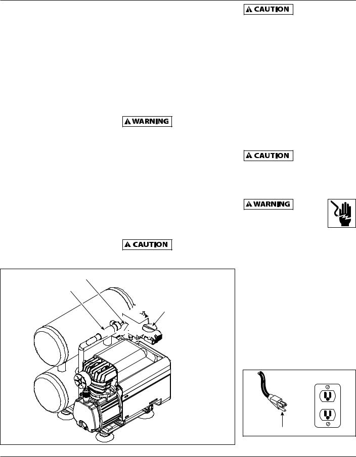
Refer to Figure 1 to locate the following items.
Pressure Switch - Auto/Off Switch - In the "auto" position, the compressor shuts off automatically when tank pressure reaches the maximum preset pressure. In the "off" position, the compressor will not operate. This switch should be in the "off" position when connecting or disconnecting the power cord from the electrical outlet.
Regulator - The regulator controls the amount of air pressure at the hose outlet.
ASME Safety Valve - This valve automatically releases air if the tank pressure exceeds the preset maximum.
Exhaust Tube - This tube carries compressed air from the pump to the check valve. This tube becomes very hot during use. To avoid the risk of severe burns, never touch the discharge tube.
Outlet Pressure Gauge - Will show air pressure at the outlet in pounds per square inch (psi). Make sure this gauge reads ZERO (by adjusting regulator knob fully counterclockwise) before changing air tools or disconnecting air hose from outlet.
Tank Pressure Gauge - Will show air pressure in tank while the compressor is running, indicating compressor
is building pressure properly. This gauge will show maximum pressure of compressor when it shuts off automatically at the pressure switch.
Check Valve - One-way valve that allows air to enter the tank, but prevents air in the tank from flowing back into the compressor pump.
Handle - Designed to move the compressor.
Never use the handle on wheeled
units to lift the unit completely off the ground.
Drain Valve - This valve is located on the bottom of the tank. Use this valve to drain moisture from the tank daily to reduce the risk of corrosion.
Motor Reset - (not shown, located inside motor). Designed to keep the motor from overheating. The motor has an auto reset protector. To reset once the motor has cooled, turn the pressure switch to the OFF position, then to the AUTO position.
This compressor is equipped with an overload protector which will shut off
motor if it becomes overloaded.
Tank Pressure Gauge |
|
Handle |
Pressure Switch |
|
(AUTO / OFF) |

 Outlet Pressure Gauge


 Regulator
Figure 1 - Unit Identification
If the overload protector is
actuated, the motor must be allowed to cool down for approximately 30 minutes before it will reset.
Installation
Location
It is extremely important to install the compressor in a clean, dry, and well ventilated area. The compressor must be placed on a firm, level surface where the surrounding air temperature will not be more than 100°F.
A minimum clearance of 18 inches between the compressor and a wall is required because objects could obstruct air flow.
Do not locate the compressor air inlet
near steam, paint spray, sandblast areas or any other source of contamination. This debris will damage the motor.
Electrical Installation
All wiring and
electrical connections should be performed by a qualified electrician. Installation must
be in accordance with local codes and national electrical codes.
Wiring
1.Local electrical wiring codes differ from area to area. Source wiring, plug and protector must be rated for at least the amperage and voltage indicated on motor nameplate, and meet all electrical codes for this minimum.
2.Use a slow blow fuse or a circuit breaker.
3.This product is for use on a nominal 120 volt circuit and has a grounding plug that looks like the plug illustrated in Figure 2.
Grounded Outlet
TEST RESET
Grounding Pin
Figure 2 - Grounding Method
www.chpower.com
3
Operating Instructions and Parts Manual
Installation (Continued)
Make sure the product is connected to an outlet having the same configuration as the plug. This product must be grounded. In the event of an electrical short circuit, grounding reduces risk of electrical shock by providing an escape wire for electric current. This product
is equipped with a cord having a grounding wire with an appropriate grounding plug. Plug must be plugged into an outlet that is properly installed and grounded in accordance with all local codes and ordinances.
Overheating, short circuiting and fire
damage will result from inadequate wiring.
Minimum Gauge of Extension Cord
25 ft. |
50 ft. |
100 ft. |
14 |
12 |
10 |
|
|
|
Use of an extension cord may cause excess heat to motor. This could lead to tripped breaker (at electrical panel) or tripped thermal overload (on compressor motor). If this occurs, eliminate extension cord and plug compressor directly into electrical outlet. Avoid using extension cords; use longer air hose(s) instead.
Lubrication
This unit is shipped without oil!
Follow lubrication instructions before operating compressor.
Use oil shipped with the compressor.
Do not use regular automotive oil such as 10W-30. Additives in regular motor oil can cause valve deposits and reduce pump life. For maximum pump life, drain and replace oil after the first hour of run time.
The compressor pump takes approximately 175mL (6 oz.) of oil. The sight glass, located on the crankcase portion of the pump, is used to determine proper oil level. Fill the crankcase with oil until the level is in the middle of the sight glass. Avoid overfilling by adding oil gradually and checking the oil level with the sight glass several times. Add enough oil to reach the “max” level on the sight glass. Proper oil level is illustrated in Figure 3.
Max. |
Min. |
Figure 3 - Proper Oil Level
Operation
Before First Start-Up
Break-In Procedure
(Complete this procedure before using compressor for the first time. Once completed, it is not necessary to repeat.)
1.Open drain valve located on bottom of tank.
2.Turn Auto/off switch to OFF position.
3.Plug in power cord.
4.Turn Auto/off switch to Auto position and run compressor for 30 minutes.
5.Turn Auto/off switch to OFF position.
6.Unplug power cord.
7.Close drain valve.
The compressor is now ready for use.
Operating Procedure
1.Turn switch to OFF position and plug in power cord.
2.Turn regulator knob counterclockwise to close air flow.
3.Turn switch to AUTO position.
4.Compressor will build to maximum pressure and shut off.
5.With hose attached to outlet of compressor, attach tire chuck or other tool to open end of hose.
6.Adjust regulator to proper pressure for tool or tire. Operate tool per instructions.
As air is depleted from the tank by use of a tire chuck, tool, etc., the compressor will restart automatically at its preset “cut-in” pressure. When a tool is being used continuously, the compressor will cycle on and off automatically.
7.Turn switch to OFF position, unplug power cord and drain tank of air when finished using compressor.
cycling of compressor
In the AUTO position, the compressor pumps air into the tank. When a shut-off (preset “cut-out”) pressure is reached, the compressor automatically shuts off.
If the compressor is left in the AUTO position and air is depleted from the tank by use of a tire chuck, tool, etc., the compressor will restart automatically at its preset “cut-in” pressure. When
a tool is being used continuously, the compressor will cycle on and off automatically.
In the OFF position, the pressure switch cannot function and the compressor will not operate. Make sure switch
is in OFF position when connecting or disconnecting power cord from electrical outlet.
Maintenance
Disconnect, tag and lock out power source, then release all pressure from the system
before attempting to install, service, relocate or perform any maintenance.
Check compressor often for any visible problems and follow maintenance procedures each time compressor is used.
ASME Safety Valve
Do not remove or attempt to adjust
the safety valve!
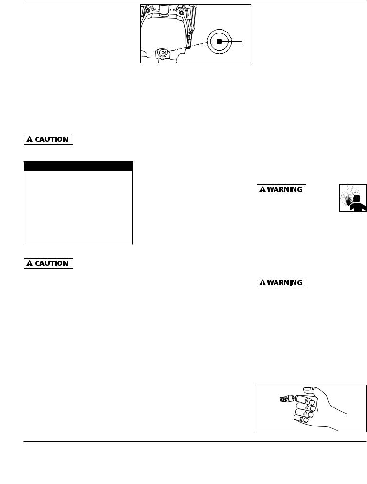
Check the safety valve by performing the following steps:
1.Plug the compressor in and run until shut off pressure is reached.
2.Wearing safety glasses, pull the ring on the safety valve to release pressure from compressor tank. Use your other hand to deflect fastmoving air from being directed toward your face.
Figure 4
www.chpower.com
4
HL540200
Maintenance (Continued)
3.The safety valve should automatically close at approximately 40 psi - 50 psi. If the safety valve does not allow air to be released when you pull on the ring, or if
it does not close automatically, it MUST be replaced.
Safety valve must be replaced if it cannot
be actuated or it leaks air after ring is released.
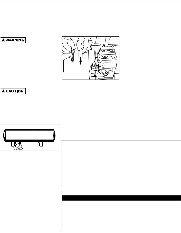
Drain Tank
1.Turn compressor off and release pressure from system. (To release pressure from system, pull ring on ASME safety valve. Deflect escaping air by shielding valve with one hand as you pull ring with other hand.) Pull ring until tank is empty.
A large amount of fast moving air will
be released when the safety valve is opened with pressure in the tank. Wear ANSI approved Z87.1 safety glasses.
2.Drain moisture from tank by opening drain valve underneath tank. Tilt tank to remove all moisture.
Figure 5
3.Clean dust and dirt from tank, air lines and pump cover while compressor is still OFF.
Oil Change
1.Allow compressor to run and warm up oil. Unplug unit.
other types of oil will cause starting problems.
5.Change oil after every 50 hours of use.
Intake Air Filter Maintenance
Removal, Inspection and Replacement
(Figure 6). |
Filter |
element |
Filter |
cover |
Figure 6 - Intake filter maintenance
The intake filter element should be removed and checked periodically. A clogged intake filter can decrease
compressor performance and cause the compressor to overheat.
1.Rotate the filter cover counterclockwise and remove.
2.Remove the filter element and inspect.
3.If the filter element is dirty or clogged, replace it.
4. Reinstall filter and cover.
Important: Locate unit as far from spraying area as hose will allow to prevent overspray from clogging filter.
End of operation/Storage
1.Turn AUTO/off switch to the OFF position.
2.Unplug power cord from wall outlet and wrap around handle to prevent damage when not in use.
3.Wearing safety glasses drain tank of air by pulling the ring on the safety valve. Use other hand to deflect fast moving air from being directed toward your face.
4.Drain tank of condensation by opening drain valve on bottom of tank. Tank pressure should be below 10 psi when draining tank.
5.Air hose should be disconnected from compressor and hung open ends down to allow any moisture to drain.
6.Compressor and hose should be stored in a cool, dry place.
Technical Service
For information regarding the operation or repair of this product, please call 1-800-543-6400.
Moisture in compressed air
Moisture in compressed air will form into droplets as it comes from an air compressor pump. When humidity is high or when a compressor is in continuous use for an extended period of time, this moisture will collect in the tank. When using a paint spray or sandblast gun, this water will be carried from the tank through the hose, and out of the gun as droplets mixed with the spray material.
Important: This condensation will cause water spots in a paint job, especially when spraying other than water based paints. If sandblasting, it will cause the sand to cake and clog the gun, rendering it ineffective.
A filter in the air line, located as near to the gun as possible, will help eliminate this moisture.
2.Position a pan under pump end of unit.
3.Remove drain plug. Allow oil to collect in pan. Tilt unit to completely drain.
4.Replace drain plug, fill pump to center of sight glass. Use Chevron synthetic 5W-30, Mobil 1 5W-30 or 10W-30 synthetic motor oil. Using
MAINTENANCE SCHEDULE
Operation |
Daily |
Weekly |
Monthly |
3 Months |
Check Oil Level |
λ |
|
|
|
Drain Tank |
λ |
|
|
|
|
|
|
|
|
Check Air Filter |
|
λ |
|
|
Check Safety Valve |
|
λ |
|
|
|
|
|
|
|
Clean Unit |
|
|
λ |
|
Change Oil |
|
|
|
λ |
www.chpower.com
5

Operating Instructions and Parts Manual
Troubleshooting Chart
Symptom |
Possible Cause(s) |
Corrective Action |
||||
Compressor will not |
1. No electrical power |
1. |
Plugged in? Switch on? Check fuse/breaker |
|||
run |
2. |
Breaker open |
2. |
Reset, determine cause of problem |
||
|
||||||
|
3. |
Pressure switch bad |
3. |
Replace |
||
|
4. |
Motor over worked |
4. |
Turn off, let cool, turn on. |
||
|
5. |
Tank pressure above cut-in |
5. |
Bleed tank pressure down to cut-in. |
||
|
|
|
|
|
|
|
Fuses blow / circuit |
1. Incorrect size fuse, circuit |
1. |
Check for proper fuse, use time-delay fuse. Disconnect |
|||
breaker trips |
|
overloaded |
|
|
other electrical appliances from circuit or operate |
|
repeatedly |
|
|
|
|
compressor on its own branch circuit. |
|
|
2. |
Extension cord usage - wrong |
2. |
Remove extension cord or refer to Extension Cord Chart on |
||
|
|
gauge wire and/or too long. |
|
|
page 4. |
|
|
3. |
Worn check valve |
3. |
Replace check valve. |
||
|
|
|
|
|
|
Do not disassemble check valve with |
|
|
|
|
|
|
|
|
|
|
|
|
|
air pressure in tank; bleed tank. |
|
|
|
|
|
|
|
|
4. |
Defective unloader valve (on |
4. |
Replace unloader valve. |
||
|
|
pressure switch) |
|
|
|
|
|
5. |
Defective motor capacitor(s) |
5. |
Replace capacitor(s) |
||
|
6. |
Defective motor |
6. |
Replace motor |
||
|
|
|
|
|
|
|
Tank pressure drops |
1. Loose connections (fittings, |
1. |
Check all connections with soap and water solution. |
|||
when compressor |
|
tubing, etc.) |
|
|
Tighten; or remove and apply pipe dope or pipe tape to |
|
shuts off |
|
|
|
|
the threads, then reassemble. |
|
|
2. |
Open tank drain valve |
2. |
Close tank drain valve |
||
|
3. |
Tank leaks |
3. |
Check tank for leaks with soap and water solution. If |
||
|
|
|
|
|
leak is detected, tank must be replaced with genuine |
|
|
|
|
|
|
replacement part. |
|
Compressor runs continuously and / or air output is lower than normal / low discharge pressure
1. |
Excessive air usage |
1. |
Decrease air usage; compressor not large enough for air |
|
|
|
requirement |
2. |
Clogged intake filter |
2. |
Clean or replace filter |
3. |
Open tank drain valve |
3. |
Close tank drain valve |
4. |
Air leaks in piping (on machine |
4. |
Check all connections with soap and water solution. |
|
or in outside system) |
|
Tighten; or remove and apply pipe dope or pipe tape to |
|
|
|
the threads, then reassemble. |
5. |
Piston ring worn |
5. |
Replace piston and cylinder. |
6. |
Broken valve (in pump) |
6. |
Replace valve |
7. |
Tank leaks |
7. |
Check tank for leaks with soap and water solution. If |
|
|
|
leak is detected, tank must be replaced with genuine |
|
|
|
replacement part. |
|
8. |
Defective pressure switch |
8. |
Replace switch |
|
|
|
|
|
Excessive moisture in |
1. |
Excessive water in tank |
1. |
Drain tank |
discharge air |
2. |
High humidity |
2. |
Move to area of less humidity; use air line filter |
|
www.chpower.com
6

|
|
|
|
|
|
HL540200 |
|
|
|
|
|
|
|
Troubleshooting Chart (Continued) |
|
|
|
|
||
|
|
|
|
|
|
|
Symptom |
Possible Cause(s) |
Corrective Action |
||||
Tank pressure drops when |
1. Circuit overloaded |
1. |
Disconnect other electrical appliances from circuit or |
|||
compressor shuts off |
|
|
|
|
operate compressor on its own branch circuit |
|
|
2. |
Low voltage |
2. |
Check voltage at wall outlet with voltmeter. |
||
|
3. |
Extension cord usage - wrong |
3. |
Remove extension cord or refer to Extension Cord Chart on |
||
|
|
gauge wire and/or too long. |
|
|
page 4 |
|
|
4. |
Loose electrical connections |
4. |
Check all electrical connections |
||
|
5. |
Worn check valve |
5. |
Replace check valve |
||
|
|
|
|
|
|
Do not disassemble check valve with |
|
|
|
|
|
|
|
|
|
|
|
|
|
air pressure in tank; bleed tank. |
|
|
|
|
|
|
|
|
6. |
Defective unloader valve (on |
6. |
Replace unloader valve |
||
|
|
pressure switch) |
|
|
|
|
|
7. |
Defective motor capacitor(s) |
7. |
Replace capacitor(s) |
||
|
8. |
Defective motor |
8. |
Replace motor |
||
Compressor runs continuously and air output is lower than normal/low discharge pressure
1.Lack of proper ventilation / 1. Move compressor to well ventilated area room temperature too high
2. |
Clogged intake filter |
2. |
Clean or replace filter |
3. |
Circuit overloaded |
3. |
Check for proper fuse, use time-delay fuse. Disconnect |
|
|
|
other electrical appliances from circuit or operate |
|
|
|
compressor on its own branch circuit |
|
4. |
Extension cord usage - wrong |
4. |
Remove extension cord or refer to Extension Cord Chart on |
||
|
|
gauge wire and/or too long. |
|
|
page 4 |
|
|
5. |
Worn check valve |
5. |
Replace check valve |
||
|
|
|
|
|
|
Do not disassemble check valve with |
|
|
|
|
|
|
|
|
|
|
|
|
|
air pressure in tank; bleed tank. |
|
|
|
|
|
|
|
|
6. |
Defective unloader valve (on |
6. |
Replace unloader valve. |
||
|
|
pressure switch) |
|
|
|
|
|
7. |
Defective motor |
7. |
Replace motor |
||
|
|
|
|
|
|
|
Knocks, rattles, and/or |
1. Loose mounting bolts |
1. |
Tighten bolts. |
|||
excessive vibration |
2. |
Tank not level |
2. |
Use sturdy wedge/object to bring tank to level position. |
||
|
||||||
|
3. |
Cylinder or piston is worn/ |
3. |
Replace or repair as necessary. |
||
|
|
scored |
|
|
|
|
|
|
|
|
|
|
|
Compressor runs |
1. Defective pressure switch |
1. |
Replace switch. |
|||
continuously and safety |
2. Defective safety valve |
2. |
Replace safety valve with genuine replacement part. |
|||
valve opens as pressure |
|
|
|
|
|
|
rises |
|
|
|
|
|
|
|
|
|
|
|
|
|
Air leaking from |
1. Check valve stuck in an open |
1. |
Replace check valve. |
|||
unloader valve on |
|
position |
|
|
|
|
pressure switch |
2. |
Unloader valve stuck in open |
2. |
Replace unloader valve. |
||
|
||||||
|
|
position |
|
|
|
Do not disassemble check valve with |
|
|
|
|
|
||
|
|
|
|
|
|
air pressure in tank; bleed tank. |
|
|
|
|
|
|
|
www.chpower.com
7

Operating Instructions and Parts Manual

 3 2
3 2


29 


|
|
|
27 |
|
|
|
28 |
|
|
|
26 |
|
|
4 |
1 |
|
|
|
|
|
|
|
25 |
5 |
23 |
|
24 |
|
|
7
9 8
22 21 5
19
8 |
|
9 |
20 |
6 |
|
|
18 |
10
16
12
11 |
|
14 |
17 |
13 |
|
||
|
|
|
14 
 15
15 


Figure 7 - Repair parts illustration for model HL540200
www.chpower.com
8

HL540200
For Replacement Parts or Technical Assistance,
Call 1-800-543-6400
Please provide following information: |
Address any correspondence to: |
- Model number |
Attn: Customer Service |
- Serial number (if any) |
100 Production Drive |
- Part description and number as shown in parts list |
Harrison, OH 45030 U.S.A. |
Replacement Parts List
Ref. |
|
Part |
|
No. |
Description |
no. |
Qty. |
|
|
|
|
1 |
Shroud |
υ |
1 |
2 |
Elbow |
HL030200AV |
1 |
3 |
Pump/motor |
— |
1 |
4 |
Power cord |
— |
1 |
5 |
Pressure gauge |
HL030400AV |
2 |
6 |
Check valve |
HL030500AV |
1 |
7 |
Grip |
— |
1 |
8 |
Ferrule |
ν |
2 |
9 |
Nut |
ν |
2 |
10 |
Exhaust tube |
ν |
1 |
11 |
Drain valve |
HL030700AV |
1 |
12 |
Tank assembly |
— |
1 |
13 |
Bolt - M6 x 12 |
κ |
2 |
14 |
Washer - M6 |
λ |
6 |
15 |
Bolt - M6 x 16 |
λ |
4 |
16 |
Base |
— |
1 |
17 |
Foot |
λ |
4 |
18 |
Plug |
— |
1 |
19 |
Pressure regulator |
HL030800AV |
1 |
20 |
Close nipple |
— |
1 |
Ref. |
|
Part |
|
No. |
Description |
no. |
Qty. |
|
|
|
|
21 |
Safety valve |
HL030900AV |
1 |
22 |
Pressure switch |
HL031000AV |
1 |
23 |
Ferrule |
σ |
2 |
24 |
Nut |
σ |
2 |
25 |
Unloader tube |
σ |
1 |
26 |
Motor cord |
— |
4 |
27 |
Washer - M5 |
υ |
10 |
28 |
Shroud screw - M5 x 16 |
υ |
10 |
29 |
Air filter |
HL030100AV |
1 |
|
|
|
|
REPLACEMENT PARTS KITS |
|
|
|
σ |
Unloader tube kit |
HL032500AV |
|
ν |
Exhaust tube kit |
HL032300AV |
|
λ |
Foot kit |
HL032400AV |
|
υ |
Shroud kit |
HL031100AV |
|
—Not Available
κStandard hardware item - available at your local hardware store
www.chpower.com
9
Operating Instructions and Parts Manual |
|
|
|
|
|
|
46 |
|
|
|
|
2 |
|
|
|
|
1 |
|
|
|
47 |
|
|
|
|
3 |
|
|
|
|
4 |
|
|
|
|
5 |
|
|
|
|
6 |
7 |
|
|
|
|
|
|
|
|
|
5 |
|
|
|
8 |
|
10 |
|
|
|
|
|
|
|
9 |
|
|
|
13 |
|
|
22 |
|
|
|
|
|
|
14 |
|
|
|
45 |
|
|
|
|
|
16 |
|
11 |
|
41 |
|
|
|
|
|
12 |
15 |
|
40 |
42 |
|
|
|||
15 |
|
|
|
|
|
|
|
17 |
|
18 |
|
|
|
|
44 |
|
19 |
|
|
|
|
||
|
|
|
|
|
|
|
43 |
|
|
21 |
|
|
|
|
|
|
20 |
22 |
|
|
|
|
33 |
|
|
|
|
38 |
39 |
34 |
|
|
30 |
23 |
|
|
|||
|
|
|
|
||||
|
|
|
|
|
|
|
|
|
29 |
|
|
|
37 |
|
|
|
|
|
|
|
|
|
|
|
24 |
|
|
|
36 |
|
|
|
|
|
|
35 |
|
|
|
25 |
|
|
|
|
|
|
|
26 |
|
|
32 |
33 |
|
|
|
|
|
31 |
|
34 |
|
|
|

 1 28 27 18
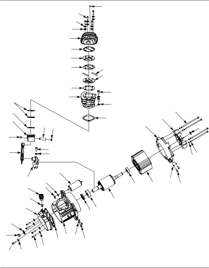
Figure 8 - Repair parts illustration for HL360000AV pump/motor
www.chpower.com
10
HL540200
For Replacement Parts or Technical Assistance,
Call 1-800-543-6400
Please provide following information: |
Address any correspondence to: |
- Model number |
Attn: Customer Service |
- Serial number (if any) |
100 Production Drive |
- Part description and number as shown in parts list |
Harrison, OH 45030 U.S.A. |
Replacement Parts List
Ref. |
|
Part |
|
No. |
Description |
no. |
Qty. |
|
|
|
|
1 |
Lock washer - M6 |
σ υ |
8 |
2 |
Head bolt - M6 x 50 |
σ |
4 |
3 |
Cylinder head |
σ |
1 |
4 |
Head gasket |
|
1 |
5 |
Valve plate |
|
2 |
6 |
Metal gasket |
|
1 |
7 |
Valve |
|
2 |
8 |
Valve plate gasket |
|
1 |
9 |
Cylinder |
ν |
1 |
10 |
Cylinder bolt - M8 x 25 |
ν |
2 |
11 |
Cylinder gasket |
|
1 |
12 |
Wrist pin |
|
1 |
13 |
Compression ring |
|
2 |
14 |
Oil ring |
|
1 |
15 |
Wrist pin retainer |
|
2 |
16 |
Piston |
|
1 |
17 |
Connecting rod |
HL030300AV |
1 |
18 |
Bolt - M6 x 20 |
υ |
5 |
19 |
Nut - M6 |
κ |
1 |
20 |
Eccentric |
— |
1 |
21 |
Capacitor |
λ |
1 |
22 |
Lock washer - M8 |
ν λ |
3 |
23 |
Nut - M8 |
λ |
1 |
24 |
Crankcase cover |
υ |
1 |
25 |
O-ring |
|
1 |
26 |
Sight glass |
|
1 |
27 |
O-ring |
|
1 |
28 |
Drain plug - M5 x 10 |
|
1 |
29 |
O-ring |
6 |
1 |
30 |
Breather |
6 |
1 |
31 |
Crankcase cover gasket |
|
1 |
32 |
Crankcase |
— |
1 |
33 |
Washer - M5 |
κ |
4 |
34 |
Shroud screw - M5 x 16 |
κ |
4 |
35 |
Oil seal |
— |
1 |
Ref. |
|
Part |
|
No. |
Description |
no. |
Qty. |
|
|
|
|
36 |
Bearing |
— |
1 |
37 |
Rotor |
— |
1 |
38 |
Bearing |
— |
1 |
39 |
Stator (with thermal protector) — |
1 |
|
40 |
Rear end bell |
— |
1 |
41 |
Fan |
τ |
1 |
42 |
Snap ring |
τ |
1 |
43 |
Plain washer - M5 |
κ |
4 |
44 |
Lock washer - M5 |
κ |
4 |
45 |
Motor bolt - M5 x 120 |
κ |
4 |
46 |
Easy start valve |
HL036200AV |
1 |
47 |
Washer |
σ |
4 |
|
|
|
|
REPLACEMENT PARTS KITS |
|
|
|
σ |
Cylinder head kit |
HL031200AV |
|
ν |
Cylinder kit |
HL031500AV |
|
λ |
Capacitor kit |
HL036400AV |
|
υ |
Crankcase cover kit |
HL031800AV |
|
τ |
Fan kit |
HL032200AV |
|
|
Piston kit |
HL031600AV |
|
|
Valve plate kit |
HL031400AV |
|
|
Sight glass kit |
HL031900AV |
|
|
Drain plug kit |
HL032000AV |
|
|
Gasket kit |
HL031300AV |
|
6 |
Breather kit |
HL032100AV |
|
—Not Available
κStandard hardware item - available at your local hardware store
www.chpower.com
11
 Loading...