


Azur 640-C
Gallery Court Hankey Place London SE1 4BB UK
Tel: +44 (0)20 7940 2200 Fax: +44 (0)20 7940 2233
640C
Issue Date: 22
nd
December 2004
________________________________________________________________________
SERVICE MANUAL
________________________________________________________________________
SPECIFICATIONS:
D/A Converter Wolfson
WM8740
24-Bit/192kHz
Capable
Freq response (-0.5dB) 10Hz to 20kHz
THD <-92dB
Dynamic Range <105dB
Channel Separation >75dB
Jitter (correlated) <260pS
Digital Outputs Opt and Coax
Dimension (mm) (H x W x D) 70 x 430 x 310
Weight (kg) 4.6
AP14839/2
1

640C SERVICE MANUAL
TABLE OF CONTENTS
Safety Precautions & Important Notes
3
Laser Safety Precautions
4
Exploded Assembly Diagram
5
Main Assembly BOM (Silver Unit)
6-8
Front Panel PCB Schematic
9
Front Panel PCB Layout (Top Side)
10
Front Panel PCB Layout (Bottom Side)
11
Front Panel PCB BOM (Silver Unit)
12/13
Servo PCB Schematic
14
Servo PCB Schematic (Power Supply)
15
Servo PCB Layout (Top Side)
16
Servo PCB Layout (Bottom Side)
17
Servo PCB BOM
18/19
DAC PCB Schematic
20
DAC PCB Layout (Top Side)
21
DAC PCB Layout (Bottom Side)
22
DAC PCB BOM
23
Mains Input PCB Schematic
24
Mains Input PCB Layout (Top Side)
25
Mains Input PCB Layout (Bottom Side)
26
Mains Input PCB BOM
27
IC Pin Layout Details
28-33
Silver / Black Differences BOM
34
2

SAFETY PRECAUTIONS & IMPORTANT NOTES
1.Check that the rear of the product indicates the correct supply voltage
for you area.
2. The lighting flash with the arrowhead within an equilateral
triangle is intended to alert the user or service agent to the
presence of dangerous voltages within the product enclosure
that may be of sufficient magnitude to constitute a risk of
electric shock to persons.
3. The exclamation point within an equilateral triangle is
intended to alert the user or service agent to the presence of
important operating and maintenance (Servicing) instructions
in the literature accompanying the appliance.
4. This product complies with EEC Low Voltage (73/23/EEC) and
Electromagnetic Compatibility (89/336/EEC) Directives when used and
serviced in accordance with this manual. For continued compliance all
components marked safety and EMC critical must only be replaced by
Cambridge Audio approved parts.
5. Any unauthorised design alterations or additions will void the
manufacturer’s warranty; furthermore the manufacturer cannot accept
responsibility for personal injury or property damage resulting therefrom.
6. When servicing, care should be taken to observe the original routing
and dressing of the leads and it should be confirmed that they have been
returned to normal after re-assembly.
Notes on chip component replacement
Never reuse a component that has been removed from a PCB
Notice that the minus side of a tantalum capacitor may be damaged by heat
COPYRIGHT NOTICE.
© 2005 Audio Partnership PLC. All rights reserved.
Cambridge Audio and Azur are registered trademarks of Audio Partnership PLC. This document
may not be reproduced, distributed, transmitted, displayed, published, or broadcast without the
express written prior permission of Audio Partnership PLC.
Alteration or removal of any trademark, copyright, or other notice from this content is prohibited.
Information provided in this document is provided solely for the use of official service agents in
repairing and servicing Audio Partnership PLC products.
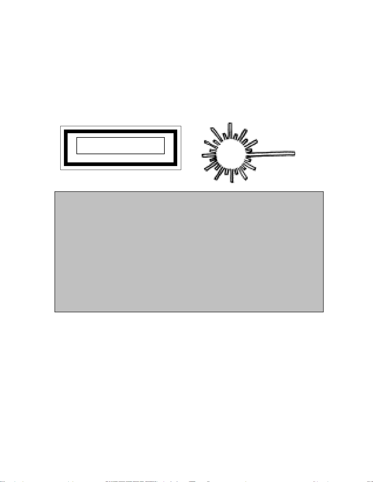
LASER SAFETY PRECAUTIONS
Caution: These labels may be attached to the unit on the rear and inside to
inform that it contains a laser component. Use of controls or adjustments, or
performance of procedures other than those specified within the service or
instruction manual may result in hazardous radiation exposure.
WARNING!
1. Service should only be performed by qualified personnel.
2. This equipment has been designed and manufactured to meet
international safety standards; it is the legal responsibility of the repairer to
ensure that these safety standards are maintained.
3. Any repairs must be made in accordance with the relevant safety
standards.
4. It is essential that safety and EMC critical components are replaced with
Cambridge Audio approved parts only.
CLASS 1 LASER PRODUCT
NOTES ON HANDLING THE OPTICAL PICK-UP BLOCK OR BASE UNIT
The laser diode in the optical pick-up block may suffer electrostatic breakdown because of the
potential difference generated by the charged electrostatic load, etc. on clothing and the human
body.
During repair, pay attention to electrostatic breakdown and also use the procedure in the printed
matter which is included in the repair parts.
The flexible board is easily damaged and should be handled with care.
NOTES ON LASER DIODE EMISSION CHECK
The laser beam on this model is concerated so as to be focused on the disc reflective surface b
y
the objective lens in the optical pick-up block. Therefore, when checking the laser diode
emission, observe from more than 30cm away from the objective lens.
4
26/11/04
8
GTL
DRAWING.
AP16811/1
1
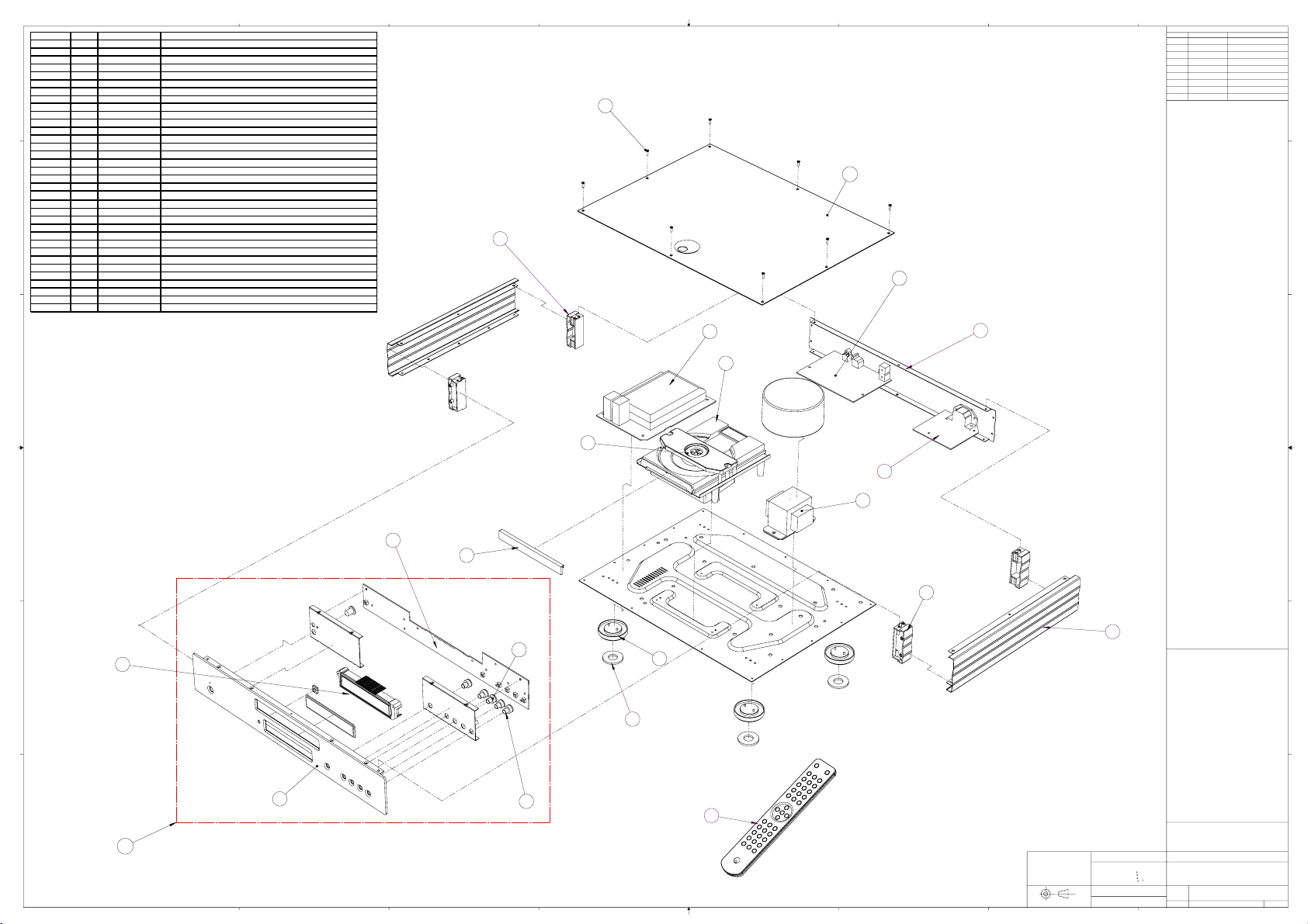
640C EXPLODED ASSEMBLY
1: ORIGINAL DRAWING 26/11/04.
2
4
18
19
1
22
17
5
6
15
14
16
9
3
10
20
13
7
21
11
12
C
DRAWING NOTES:-
REVISIONS NOTES:-
DATE
EDITOR
REV
THIRD ANGLE
PROJECTION
B
A
A
B
C
D
1
2
3
E-MAIL simon.freeth@audiopartnership
FINISH:
MATERIAL:
REVISIONS & DATE
E-MAIL nick@audiopartnership
1:5SCALE:
E-MAIL grahame@audiopartnership
FAX: 0207 940 2233
1
DO NOT SCALE FROM DRAWING
DWG. NO.
A0
SIZE
TITLE:
AUDIO PARTNERSHIP PLC
UNLESS OTHERWISE SPECIFIED:
OF 1SHEET
TEL: 0207 940 2200
LONDON SE1 4BB
HANKEY PLACE
3 GALLERY COURT
AUDIO PARTNERSHIP PLC
COPYRIGHT
0.5
--
--
PROPRIETARY AND CONFIDENTIAL
ANGULAR
0.1mm2 DECIMAL IE 75.75
OF AUDIO PARTNERSHIP IS PROHIBITED.
F
E
F
E
1
2
3
4
5
6
7
8
8
7
6
5
4
DIMENSIONS ARE IN MM's
TOLERANCES:
WHOLE NO.s IE 75 0.5mm
1 DECIMAL IE 75.5 0.2mm
THE INFORMATION CONTAINED IN THIS DRAWING IS THE SOLE PROPERTY OF
AUDIO PARTNERSHIP PLC.
ANY REPRODUCTION IN PART OR AS A WHOLE WITHOUT THE WRITTEN PERMISSION
D
Drawing re
f
AP part Internal ref Description
1 CA new side panel
2 CA new plastic insert rear
3 CA new plastic insert front
4 CA new back panel
5
PY507 6550-010204-000-01 Azur 640C Top Panel Black
5
PY508 6550-010204-000-02 Azur 640C Top Panel Silver
6
PY515
7002-608010-001 Screw M2.6 x 8 M/C Torx Recessed 1/K Head Black
6
PY516
7002-608010-006 Screw M2.6 x 8 M/C Torx Recessed 1/K Head En-Plated (silver)
7 PY586 6564-010001-000A01 Azur-640C.Front panel SILVER
7 PY582 6564-010001-000-01 Azur-640C.Front panel BLACK
8 PY587 8564-001001-301 Azur-640C Complete front panel assy (Silver) REV A
8 PY583 8564-001002-301 Azur-640C Complete front panel (BLACK) REV A
9
PY563 3200-576690-100 TRANSFORMER 115V/230V AC10V/2A 16*2/0.5A ES-57-669
10
PY541
6050-150010-000A01 PLASTIC FOOT GREY PAINT SILVER
10 PY531 6050-150010-000 PLASTIC FOOT BLACK (AP126522)
11
PY340 9692-006002-101 Mechan Assy (PU92TL-210) W/Sony KSM213CCM ReV A
12 PY790 3009-213000-000 Sony laser assy KS213CCM
13 PY719 6050-150012-000-01 7MM TAC SWITCH BUTTON (BLACK)
13 PY720 6050-150012-000A01 7MM TAC SWITCH BUTTON ( SILVER)
14 PY704
6600-170104-000 CA NEW RANGE AMP 7MM TAC SWITCH CUSHION
15 PY571 9464-001000-011 Azur-540C & 640C MAIN SERVO BOARD ASSY
16 PY588 9460-001300-581 Azur-640C DAC BOARD ASSY REV A
17 PY589 9464-001000-071 Azur-640C POWER PCB ASSY REV A
18 PY573 9805-064001-000 Azur-340/540/640AC REMOTE CONTROL ASSY
19 PY544 6600-170100-000 FOOT PAD FOR Azur-640A
20 PY568 6564-010006-000A01 Azur-640C.Silver CD DOOR W/SILKSCREEN PMS COOL GREY 7C
20 PY554 6564-010006-000-01 Azur-640C.Black CD DOOR W/SILKSCREEN PMS COOL GREY 7C
21 PY552 3110-064580-100 LCD DISPLAY ISO6458P01V0 113*25.7MM NEGATIVE (BLACK UNIT)
21 PY562 3110-064580-000 LCD DISPLAY ISO6458P00V0 113*25.7MM POSITIVE (SILVER UNIT)
22
PY556 9464-001000-041 Azur-540C & 640C CONTROL BOARD ASSY REV A
Note:user manual is downloadable from our www.cambridge-audio.co.uk
5

AP13752/3
AP Part No. DRAWING
NO
DESCRIPTION QTY COMMENTS
AP13504/1 POLY ENDCAP PACKAGING 2
AP13505/1 CARTON PACKAGING W/HANDLE 1 PRINTED TO ARTWORK AP13716/1
AP13613/1 CAMBRIDGE AUDIO AZUR WOVEN BAG FOR REMOTE CONTROL 1 PACK REMOTE CONTROL INSIDE,
CAMBRIDGE AZUR REMOTE CONTROL COMPLETE. MODEL No RC-
540AC/640AC
1 MOUNTED INTO POLY ENDCAP
PACKING IN REBATE PROVIDED
AAA ALKALINE BATTERIES 3 FOR REMOTE. PLACE IN
INSTRUCTION MANUAL POLYBAG
PY566 AP14004/1 640C CD PLAYER OWNERS' MANUAL 1
AP13945/1 CARTON LABEL (MODEL NO.) UK SILVER 1 FOR BOX
SERIAL NUMBER LABEL, BLANK (6.5X35.5mm) 3 1 X REAR PANEL, 1 X BOX, 1 X
SHIPPING CARTON
ISO 9002 LABEL 1 AFFIXED TO REAR PANEL ABOVE
IEC SOCKET
AP10087/2 "MADE UNDER LICENCE IN PRC" STICKER 1 AFFIXED TO REAR PANEL BELOW
IEC SOCKET
POLYBAG 173X260X4C mm 1 FOR INSTRUCTION
MANUALOWNERS CERTIFICATE
AND REMOTE BATTERIES
AP13612/1 CAMBRIDGE AUDIO AZUR 2 RIDGE WOVEN BAG 1 PACK AMP UNIT INSIDE
1830mm AC IEC POWER CORD SET BS STANDARD FUSED 3 AMP 1 MUST BE BS APPROVED
BLUE TAPE SEAL FOR CAMBRIDGE CARTON 1
FRONT PANEL ASSEMBLY
PY586 AP12741/1 CAMBRIDGE NEW RANGE CD FRONT PANEL (PUNCHED AND PRINTED)
(SILVER)
1 SCREENED WITH ARTWORK
AP13591/3 & AP13593/1
AP12935/1 CAMBRIDGE NEW RANGE IR LENS 1 GLUED IN PLACE ON THE FRONT
PANEL
AP13322/1 CAMBRIDGE NEW RANGE 105mm DISPLAY WINDOW 1 GLUED IN PLACE ON THE FRONT
PANEL
AP13436/2 CAMBRIDGE NEW RANGE CD SUB PANEL LEFT (POWER) 1 FASTENEND IN PLACE INBETWEEN
THE LEDGES ON THE FRONT
PANEL, ALIGN UP THE POWER
BUTTON HOLES
AP12931/1 CAMBRIDGE NEW RANGE AMP LIGHTGUIDE, CUT TO SINGLE PIPE 1 FASTEN TO SUBPLATE LEFT
(POWER)
M3 X 6 POZI PAN STP SCREW 1 AFFIXES SINGLE LIGHTGUIDE TO
SUBPLATE
M3 X 6 C/S POZI MACHINE SCREW 4 FASTEN THE SUB PLATE LEFT TO
THE FRONT PANEL
AP13585/1 CAMBRIDGE NEW RANGE AMP 9mm TAC SWITCH CUSHION 1 POSITION ON THE CONTROL BOX
BUTTON, DOWN THE MAIN SHAFT
AFFIX USING ADHESIVE PROVIDED
ON THE CUSHION.
PY145 AP11782/1 OPUS CONTROL BOX BUTTON (SILVER) 1 POSITION IN PLACE ON THE
FRONTPANEL
AP13437/2 CAMBRIDGE NEW RANGE CD SUB PANEL RIGHT (FUNCTION) 1 FASTENEND IN PLACE INBETWEEN
THE LEDGES ON THE FRONT
PANEL, ALIGN UP THE FUNCTION
BUTTON HOLES
M3 X 6 C/S POZI MACHINE SCREW 4 FASTEN THE SUB PLATE RIGHT TO
THE FRONT PANEL
AP12934/1 CAMBRIDGE NEW RANGE AMP 7mm TAC SWITCH CUSHION 5 POSITION ON THE 7mm TACT
SWITCH BUTTONS, DOWN THE
MAIN SHAFT AFFIX USING
ADHESIVE PROVIDED ON THE
CUSHION.
AP12925/1 CAMBRIDGE NEW RANGE AMP 7mm TAC SWITCH BUTTON 5 POSITION IN PLACE ON THE
FRONTPANEL
Cambridge Azur 640CCD Player (Main Assembly BOM Silver Unit)
Note, resistors, capacitors and other 'generic' electronic components are not usually stocked by the manufacturer. Please obtain these locally. 6

AP Part No. DRAWING
NO
DESCRIPTION QTY COMMENTS
BOTTOM PANEL ASSEMBLY
AP12735/5 CAMBRIDGE NEW RANGE CD BOTTOM PANEL 1
12.2mm BRASS THREADED STANDOFF 1 POSITION IN PLACE ON BOTTOM
PANEL
M3 X 8 POZI PAN MACHINE SCREW 1 TO AFFIX BRASS THREADED
STANDOFF TO BOTTOM PANEL
PY541 AP12652/2 CAMBRIDGE NEW RANGE FOOT MOULDING (SILVER) 4 POSITION IN PLACE ON BOTTOM
PANEL
PY544 AP12883/3 CAMBRIDGE NEW RANGE FOOT PAD 4 AFFIX ON FOOT USING ADHESIVE
SURFACE
M3 X 6 PLASTITE POZI PAN 4 AFFIX FEET TO BOTTOM PANEL
12.7mm PLASTIC PCB STANDOFF 7 PUSH SNAP FIT ON BOTTOM PANEL
8 mm PLASTIC PCB STANDOFF 1 PUSH SNAP FIT ON BOTTOM PANEL
M4 X 12 POZI PAN MACHINE BOLT 2 FIX THROUGH EARTHING POINT
HOLES ON BOTTOM PANEL
M4 NUT STANDARD 2 USED TO FIX ABOVE BOLTS
M4 LOCK WASHER 2 FOR EARTH BOLTS
M4 X 12 POZI PAN MACHINE BOLT 2 TO FIX THROUGH TRANSFORMER
HOLES IN BOTTOM PANEL
M4 LOCK WASHER 2 PLACE ON TRANSFORMER FIXING
BOLTS
M4 NUT STANDARD 2 USED TO FIX TRANSFORMER IN
PLACE
FW-2S PIN GOOD STICK ON CABLE CLIP 3 USED TO CLIP DAC POWER CABLE
AP13894/ AND TRANSFORMER TO
SERVO BOARD CABLE
AP13571/1 CAMBRIDGE AUDIO NEW RANGE CD TRANSFORMER PAD 1 POSITION IN PLACE ON BOTTOM
PANEL WITH THE FIXING BOLTS
THROUGH SUPPLIED HOLES
PY563 AP13157/3 CAMBRIDGE AUDIO EI 115/230V 540C/640C TRANSFORMER 1 POSITION ON TRANSFORMER PAD
WITH FIXING BOLTS THROUGH
SUPPLIED HOLES
AP13545/1 CAMBRIDGE AUDIO NEW RANGE CD TRANSFORMER CAN WITH ADHESIVE
PAD ADDED
1 SCREENED WITH ARTWORK
AP13721/1 POSITION ON TOP OF
TRANSFORMER AND PRESS TO
STICK IN PLACE
CD Mechanism with Loader 1 POSITION IN THE CORRECT
POSITION ON THE BOTTOM PANEL
PY057 CD mechanism (Sony) 1
M3 X 6 POZI PAN MACHINE SCREW 4 TO AFFIX THE CD MECH TO THE
BOTTOM PANEL
AP13895/1 MAINS PCB INSULATING SHEET 1 TO BE POSITIONED OVER
STANDOFFS UNDER POWER PCB
AP13544/2 CAMBRIDGE AUDIO NEW RANGE CD MECH TOP STICKER 1 SCREENED WITH ARTWORK
AP13763/1THEN POSITION OVER
LOCATING PIPS ON CD MECH TOP
SURFACE AND PRESS TO STICK
PY568 AP13495/1 CAMBRIDGE AUDIO NEW RANGE CD DRAW FRONT (SILVER) 1 SCREENED WITH ARTWORK
AP13601/1 POSITON ON DRAW
FRONT AND GLUE IN PLACE
M3x8 POSIPAN MACHINE SCREW 1 TO FIX SERVO BOARD TO BRASS
THREADED STAND OFF
AP13617/1 16 WAY LASER CABLE, FLEXIBLE FLAT CABLE 250mm 1 CONNECTS SERVO PCB TO LASER
BLOCK ON THE CD MECH
Note, resistors, capacitors and other 'generic' electronic components are not usually stocked by the manufacturer. Please obtain these locally. 7

AP Part No. DRAWING
NO
DESCRIPTION QTY COMMENTS
AP13618/1 5 WAY TRAY MOTOR CABLE FLAT WIRE STYLE 350mm 1 CONNECTS THE SERVO PCB TO
THE CD MECH, RUNS UNDER THE
FRONT OF THE MECH AND UNDER
THE SERVO PCB
AP13619/1 6 WAY SPINDLE MOTOR CABLE 200mm 1 CONNECTS THE SERVO PCB TO
THE CD MECH, RUNS UNDER THE
CD MECH
AP10616/6 SERVO PCB SHIELDING CAN 1 SCREENED WITH ARTWORK
AP13721/1 POSITION OVER SEVRO
PCB AND SOLDER FIX
AP10001/2 CAMBRIDGE AUDIO SCREENING CAN 1 POSITION OVER DAC PCB AND
SOLDER FIX
AP13625/1 2 WAY MUTE CABLE, FLAT WIRE STYLE CABLE 300mm 1 CONNECTS DAC PCB TO THE
SERVO PCB
AP13626/1 3 WAY SHIELDED DIGITAL OUT CABLE 130mm 1 CONNECTS DAC PCB TO THE
SERVO PCB
AP13627/1 5 WAY SHIELDED DIGITAL OUT CABLE 120mm CONNECTS DAC PCB TO THE
SERVO PCB
AP13628/1 2 WAY SHIELDED MASTER CLOCK CABLE 160mm 1 CONNECTS DAC PCB TO THE
SERVO PCB
M2.6 X 6 POZI PAN MACHINE SCREW 5 TO AFFIX BOTTOM PANEL TO SIDE,
FRONT AND REAR PANELS
M2.6 X 10 POZI PAN PLASTITE 4 FIX CORNERS OF BOTTOM PANEL
TO PLASTIC INSERTS
SIDE PANEL ASSEMBLY 2
AP12725/1 CAMBRIDGE AUDIO NEW RANGE PRESSED SIDE PANEL (2 RIDGE) (SILVER) 2 POSITION IN PLACE ON PLASTIC
FRONT INSERTS
AP12727/1 CAMBRIDGE AUDIO NEW RANGE FRONT PLASTIC SUPPORT (2 RIDGE WITH
CAPTIVE M2.6 NUTS)
2 POSITION AT FRONT WITHIN SIDE
PANELS
AP12728/1 CAMBRIDGE AUDIO NEW RANGE REAR PLASTIC SUPPORT (2 RIDGE WITH
CAPTIVE M2.6 NUTS)
2 POSITON AT REAR WITHIN SIDE
PANELS
M2.6 X 10 C/S POZI PLASTITE 8 TO AFFIX SIDE PANELS TO PLASTIC
INSERTS
D640C REAR PANEL ASSEMBLY 1
AP13435/2 CAMBRIDGE AUDIO NEW RANGE CD REAR PANEL PRINTED 1 SCREENED WITH ARTWORK
AP13669/1, THEN POSITION ON
REAR PLASTIC SUPPORTS
M3 X 10 POZI PAN PLASTITE 4 TO AFFIX REAR PANEL TO REAR
PLASTIC INSERTS
M3 X 8 POZI PAN PLASTITE 3 TO FIX DAC PCB ELECTRONIC
PARTS TO REAR PANEL
M3 X 10 POZI PAN MACHINE SCREW 2 FIXES THE IEC SOCKET MOUNTED
ON THE POWER BOARD TO THE
REAR PANEL
M3 NUT STANDARD 2 USED TO FIX ABOVE BOLTS
M3 LOCK WASHER 2 USED TO FIX ABOVE BOLTS
AP13340/1 A600 LIDDING TAPE FOR FRONT AND REAR PANELS 2 FIX TO THE CORRECT SURFACES
FOR LID
AP13342/1 A600 LIDDING TAPE FOR SIDE PANELS 2 FIX TO THE CORRECT SURFACES
FOR LID
PY574 AP12733/2 CAMBRIDGE AUDIO NEW RANGE TOP PANEL WITHOUT VENTS (SILVER) 1 POSITIONON TOP OF THE
PRODUCT
PY516 M2.6 X 6 C/S TORX MACHINE SCREW (SILVER) 8 TO AFFIX TOP PANEL TO PLASTIC
INSERTS, SIDE, REAR AND FRONT
PANEL
Note, resistors, capacitors and other 'generic' electronic components are not usually stocked by the manufacturer. Please obtain these locally. 8
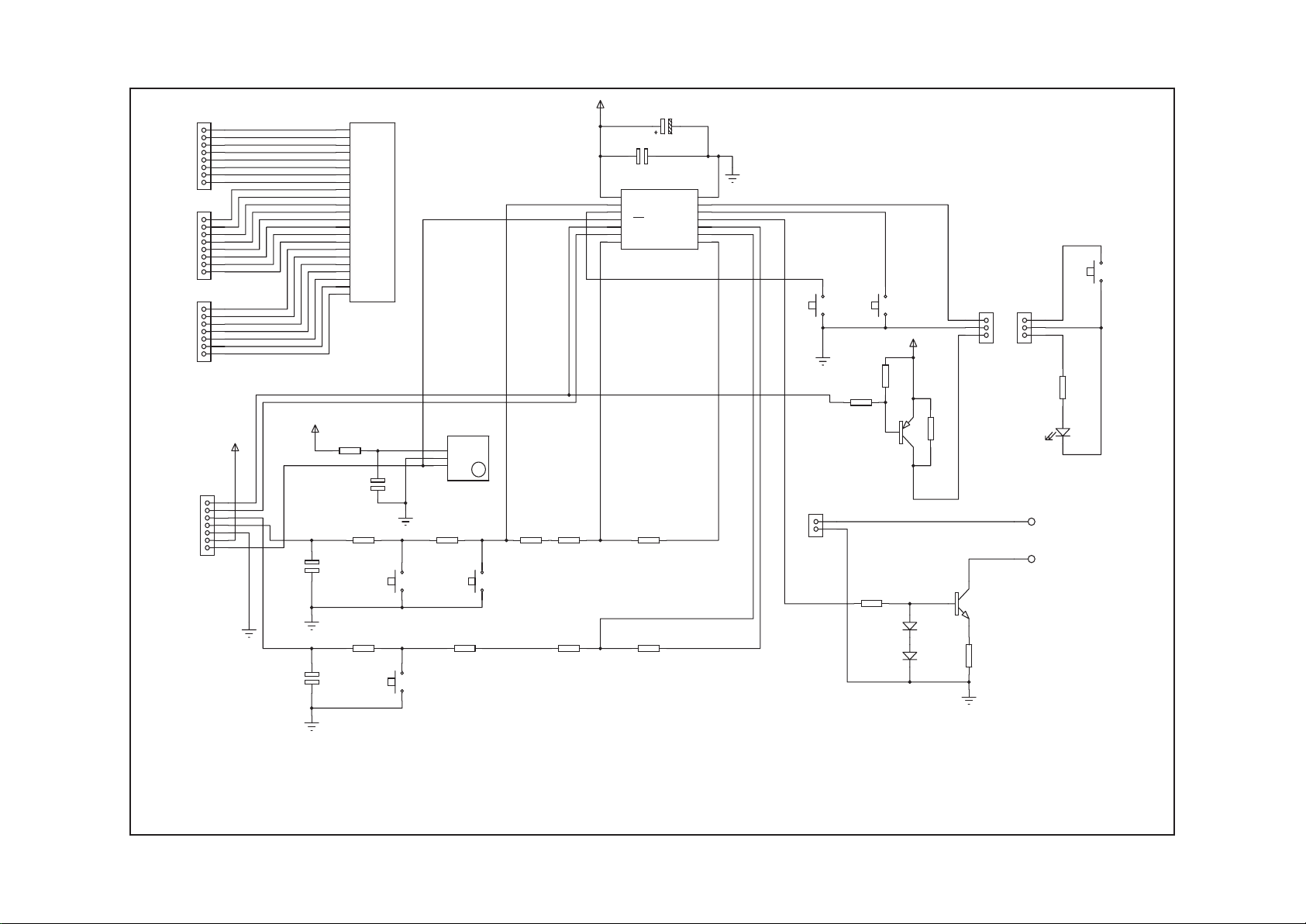
Cambridge Audio Azur 640C CD Player
AP12992/3 Front Panel PCB Schematic
SW1
PLAY/PAUSE
SW2
STOP
SW3
OPEN/CLOSE
1
2
CN1
CONN-H2
SEG11
16
SEG10
15
SEG9
14
SEG8
13
SEG7
12
SEG6
11
SEG5
10
SEG4
9
SEG3
8
SEG2
7
SEG1
6
SEG0
5
COM3
4
COM2
3
COM1
2
COM0
1
SEG12
17
SEG13
18
SEG14
19
SEG15
20
SEG16
21
SEG17
22
SEG18
23
LCD1
LCD
PACKAGE=LCD D600
1
2
3
4
5
6
7
8
CN2
CONN-H8
1
2
3
4
5
6
7
8
CN3
CONN-H8
1
2
3
4
5
6
7
CN4
CONN-H7
R3
27K
R4
33K
R5
2K7
R6
10K
R7
82K
R8
1K5
R9
82K
C1
100n
+5V
C2
1000p
C3
1000p
R10
68K
R11
3K3
+5V
FORWARD SKIP FORWARD SEARCH
BACKWARD SKIP BACKWARD SEARCH
SW4
SW-TACT
SW5
SW-TACT
+5V
3
OPT
1
GND
2
U2
TSOP18 IR RECEI
C4
100n
R15
330R
VSS
14
RB2
11
RC4
6
RC2
8
RC3
7
RB1
12
RB4/OSC2/CLKOUT
3
RB0
13
VDD
1
RB5/OSC1/CLKIN
2
RB3/MCLR/VPP
4
RC5/TOCKI
5
RC1
9
RC0
10
U3
16C505
SW6
SW-TACT
P1
PAD
P2
PAD
PGND
R12
4K7
R13
10K
Q2
BC327
+5V
1
2
3
CN5
CONN-H3
D2
LED
Standby
1
2
3
CN6
CONN-H3
1
2
3
4
5
6
7
CN7
CONN-H7
C6
10uF 10V
R14
820R
Q1
BC337
R2
1K8
R16
33R
D1
1N4148
D3
1N4148
K1
K2
+5V
PWR DET
RESET
R1
820R
To enhance viewing, please print to A3. 9
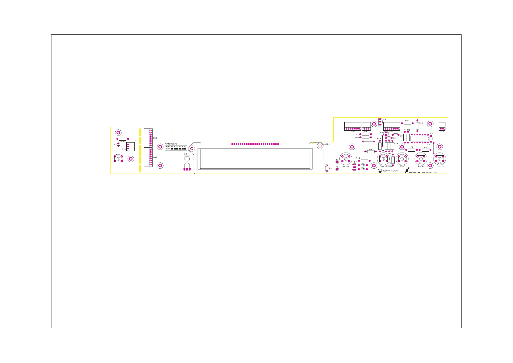
Cambridge Audio Azur 640C CD Player
AP12992/3 Front Panel PCB Layout (Top Side)
To enhance viewing, please print to A3. 10
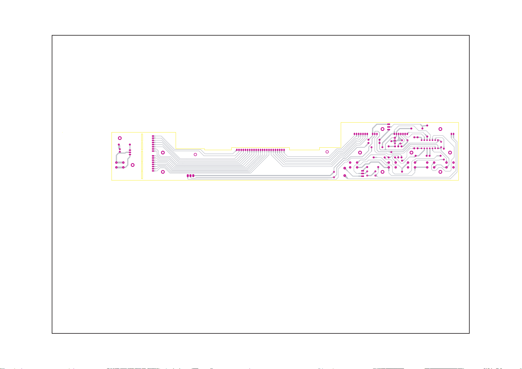
Cambridge Audio Azur 640C CD Player
AP12992/3 Front Panel PCB Layout (Bottom Side)
To enhance viewing, please print to A3. 11
 Loading...