


340A
Issue Date: 18th June 2004
________________________________________________________________________
SERVICE MANUAL
________________________________________________________________________
SPECIFICATIONS: |
|
Power Output |
40W (into 8Ω) |
|
50W (into 4Ω) |
Max Power Consumption |
345W |
Total Harmonic Distortion |
1kHz < 0.009% |
|
20kHz < 0.09% |
Frequency Response (-1dB) |
5Hz – 50kHz |
S to N Ration (unweighted) |
99dB |
Slew Rate (into 8Ω) |
20V/uS |
Dimensions (HxWxD) |
|
mm |
70 x 430 x 310 |
Inches |
2.8 x 16.9 x 12.2 |
Weight |
|
Kg |
6.2 |
Lbs |
13.6 |
AP15844/1
Gallery Court Hankey Place London SE1 4BB UK |
|
Tel: +44 (0)20 7940 2200 Fax: +44 (0)20 7940 2233 |
1 |
340A SERVICE MANUAL
TABLE OF CONTENTS
Safety Precautions & Important Notes |
3 |
|||||||||||||
Main Assembly BOM |
|
4/5 |
||||||||||||
|
|
|
|
|
|
|
|
|
|
|
|
|
|
|
Micro controller PCB Schematic (PIC’s/Switches/LED’s) |
6 |
|||||||||||||
Micro controller PCB Layout (Top Side) |
|
7 |
||||||||||||
|
|
|
|
|
|
|
|
|
|
|
|
|
||
Micro controller PCB Layout (Bottom Side) |
8 |
|||||||||||||
Front Panel PCB Assembly BOM |
|
|
9 |
|||||||||||
Main PCB Schematic (Input Select) |
|
10 |
||||||||||||
Main PCB Schematic (Power Amplifiers) |
11 |
|||||||||||||
Main PCB Schematic (Power Supplies) |
|
12 |
||||||||||||
Main PCB Schematic (Tone Control) |
|
13 |
||||||||||||
Main PCB Layout (Top Side) |
|
|
14 |
|||||||||||
Main PCB Layout (Bottom Side) |
15 |
|||||||||||||
Main PCB BOM |
|
|
16-18 |
|||||||||||
IC Pin Layout Details |
|
19/20 |
||||||||||||
Silver – Black Differences BOM |
|
21 |
||||||||||||
2

SAFETY PRECAUTIONS & IMPORTANT NOTES
1.Check that the rear of the product indicates the correct supply voltage for you area.
2.The lighting flash with the arrowhead within an equilateral triangle is intended to alert the user or service agent to the presence of dangerous voltages within the product enclosure that may be of sufficient magnitude to constitute a risk of electric shock to persons.
3.The exclamation point within an equilateral triangle is intended to alert the user or service agent to the presence of important operating and maintenance (Servicing) instructions in the literature accompanying the appliance.
4.This product complies with EEC Low Voltage (73/23/EEC) and Electromagnetic Compatibility (89/336/EEC) Directives when used and serviced in accordance with this manual. For continued compliance all components marked safety and EMC critical must only be replaced by Cambridge Audio approved parts.
5.Any unauthorised design alterations or additions will void the manufacturer’s warranty; furthermore the manufacturer cannot accept responsibility for personal injury or property damage resulting therefrom.
6.When servicing, care should be taken to observe the original routing and dressing of the leads and it should be confirmed that they have been returned to normal after re-assembly.
Notes on chip component replacement
Never reuse a component that has been removed from a PCB
Notice that the minus side of a tantalum capacitor may be damaged by heat
COPYRIGHT NOTICE.
© 2005 Audio Partnership PLC. All rights reserved.
Cambridge Audio and Azur are registered trademarks of Audio Partnership PLC. This document may not be reproduced, distributed, transmitted, displayed, published, or broadcast without the express written prior permission of Audio Partnership PLC.
Alteration or removal of any trademark, copyright, or other notice from this content is prohibited. Information provided in this document is provided solely for the use of official service agents in repairing and servicing Audio Partnership PLC products.
3
Cambridge Azur 340A Main Assembly BOM |
|
|
AP14861/4 |
||
AP PART |
DRAWING NO |
DESCRIPTION |
QTY |
|
COMMENTS |
No. |
|
|
|
|
|
|
|
Chassis Assembly |
|
|
|
|
AP14160/1 |
Bottom Panel |
1 |
|
|
PY541 |
AP12652/2 |
Foot Moulding Silver |
4 |
Position In Place on Bottom Panel |
|
PY544 |
AP12883/3 |
Foot Pad |
4 |
Affix on Foot Using Adhesive Surface |
|
|
|
M3 X 8 Plastite Pozi Pan |
4 |
Fix Feet To Bottom Panel. |
|
|
|
7mm Plastic Support |
9 |
Push Snap Fit On Bottom Panel |
|
|
|
7mm Plastic Support |
4 |
Resting Under PCB fastened to Bottom Panel |
|
|
AP14775/1 |
7mm Plastic Standoff ( Square Snap - In) |
6 |
Fastening PCB to Bottom Panel |
|
|
|
M3 X 8 Plastite Pozi Pan |
6 |
To hold PCB to Square snap-in Stand-offs |
|
|
AP14561/3 |
Transformer toroidal 230V |
1 |
|
|
|
|
Transformer bolt M8 56mm thread length |
1 |
Supplied with Transformer. Secures transformer |
|
|
|
Dished transformer plate 70 mm diam |
1 |
Supplied with Transformer. On top of transformer |
|
|
|
Rubber Washer |
2 |
Supplied with Transformer. One is fitted under the |
|
|
|
|
|
transformer and one on the top, under dished washer |
|
|
|
M8 nut |
1 |
Supplied with Transformer. Secures transformer |
|
|
|
M8 plain washer |
1 |
Supplied with Transformer. Secures transformer |
|
|
|
M8 locking washer |
1 |
Supplied with Transformer. Secures transformer |
|
|
AP15528/1 |
Cambridge Toroidal 67mm label |
1 |
Stick to top of dished transformer plate 70 mm diam. |
|
|
AP14862/2 |
Insulation Sheet |
1 |
To Be Positioned Over Standoffs Under Power PCB |
|
|
|
M4 X 12 Pozi Pan Machine Bolt |
1 |
Fix Through Earthing Point hole on Bottom Panel |
|
|
|
M4 Nut Standard |
1 |
Used To Fix Above Bolts |
|
|
|
M4 Lock Washer |
1 |
For Earth Bolts |
|
|
|
Earth point label |
1 |
Place next to earth point bolt on bottom of chassis |
|
|
PCB Gerber AP14 |
Main PCB Assembly BOM |
1 |
Fixes onto the Bottom Panel With 7mm Plastic Standoffs. |
|
|
|
|
|
Built to BOM AP15173/2 |
|
|
|
Front Panel Assembly |
|
|
|
|
AP14159/1 |
Sub Panel |
1 |
Fasten in place between the Ledges of the Front Panel, Align |
|
|
|
|
|
Up The Power Button Holes |
|
|
AP12931/1 |
Lightguide |
3 |
Fasten To Subplate. |
Input select LEDs |
|
AP12931/1 |
Lightguide (half of) |
0.5 |
Fasten To Subplate. |
Power LED |
|
|
M3 X 6 Pozi Pan Stp Screw |
4 |
Affixes Three Lightguide To Subplate |
|
PY638 |
AP14157/1 |
Front Panel (Punched And Printed) Silver |
1 |
Extrusion Details AP12738* & Screened With Artwork |
|
|
|
|
|
AP14826/1 & AP14828/2 |
|
|
AP12935/1 |
IR Lens |
1 |
Glued In Place On The Front Panel |
|
|
|
M3 X 6 C/S Pozi Machine Screw |
7 |
Fasten The Sub Plate to the Front Panel. Only 7 screws are |
|
|
|
|
|
fitted out of a possible 8. See drawing AP15536/1 |
|
|
PCB Gerber AP14 |
IR PCB Assembly (part of F/P PCB assembly) |
1 |
Fitted onto the Front Panel, bom is AP15185/2 |
|
|
|
|
|
|
|
|
|
Washer Nylon M3, 1mm Thk |
1 |
Fitted between Front Panel and IR PCB |
|
|
|
M2.6 x 4mm Pan hd Poz Taptite |
1 |
Use to fix IR PCB onto SubPanel |
|
|
AP12934/1 |
7mm TAC Switch Cushion |
6 |
Position on the 7mm tact switch Buttons, down the main |
|
|
|
|
|
shaft affix using adhesive provided on the cushion. |
|
|
AP12925/1 |
7mm TAC Switch Button |
6 |
Position In Place On The Front Panel |
|
|
AP12926/2 |
7mm Push Switch Button |
2 |
Fitted to SW1 & 2 on main PCB |
|
|
PCB Gerber AP14 |
Front Panel & MicroController PCB Assembly |
1 |
Fixes onto the Sub Panel With M3 M/C Screws. Built to BOM |
|
|
|
BOM |
|
AP 15185/2 |
|
|
|
M3 X 6 Pozi Pan Machine Screw |
7 |
Used For Fixing The Front Panel Pcb's To The Subplate |
|
|
|
|
|
Standoff's |
|
|
|
Side Panel Assembly |
|
|
|
|
AP12725/2 |
Pressed Side Panel (2 Ridge) |
2 |
|
|
|
AP12727/1 |
Front Plastic Support (2 Ridge With Captive |
2 |
Position at Front within Side Panels |
|
|
|
M2.6 Nuts) |
|
|
|
|
AP12728/1 |
Rear Plastic Support (2 Ridge With Captive M2.6 |
2 |
Position at Rear within Side Panels |
|
|
|
Nuts) |
|
|
|
|
|
M2.6 X 8 C/S Pozi Plastite |
8 |
To Affix Side Panels To Plastic Inserts |
|
|
|
Rear Panel Assembly |
|
|
|
|
AP14162/2 |
Rear Panel Printed |
1 |
Screened With Artwork AP14830/3 |
|
|
|
M3 X 10 Pozi Pan Plastite |
8 |
To fix speaker terminal and Phono sockets connectors to |
|
|
|
|
|
Rear Panel |
|
|
|
M4 X 8 Pozi Pan Plastite |
2 |
To fix IEC Power connector to Rear Panel |
|
4
AP PART |
DRAWING NO |
DESCRIPTION |
QTY |
COMMENTS |
No. |
|
|
|
|
|
|
Final assembly |
|
|
|
AP11879/3 |
Opus Control Box Powerswitch |
1 |
Position in Place on the Front Panel |
|
AP14819/1 |
Push Switch Bar Extension |
1 |
Affix and glue to Power Bar |
|
CD4P AB05a |
Power Bar |
1 |
Fitted to SW3 on main PCB |
|
AP15512/1 |
Front Panel Insulation Sheet |
1 |
Attach to main PCB with two tie-wraps |
|
|
Tie-wraps (plastic ties) Width 2.5mm |
2 |
Attach insulation strip to main PCB |
PY592 |
AP10209/3 |
Cambridge Selector Knob Mk3 Silver |
3 |
|
|
AP10224/1 |
Cambridge Knob Insert Mk2 |
3 |
Insert Into Selector Knobs |
PY590 |
AP12750/2 |
Cambridge New Range Amp Volume Knob Silver |
1 |
|
|
|
|
|
|
|
AP13361/1 |
A600 Volume Knob Blue Plastic Insert |
1 |
Insert Into Volume Knob |
|
AP13360/1 |
A600 Volume Knob Aluminium Skin |
1 |
Glued and taped In Place On Volume Knob |
|
|
M3 X 10 Pozi Pan Plastite |
4 |
To fix rear panel to side panels |
|
|
M2.6 X 6 Pozi Pan Machine Screw |
12 |
To fix Bottom Panel To Side, Front And Rear Panels |
|
|
M2.6 x ??? |
4 |
To fix Bottom Panel To Side Panels (at corners) |
|
AP14865/1 |
Cambridge Azur 340A Microcontroller |
1 |
From Main PCB J2 to Front Panel PCB CN2 |
|
|
Cableform |
|
|
|
AP14896/1 |
Cambridge Azur 340A Volume Control |
1 |
From Front Panel PCB CN5 to Volume Pot Motor |
|
|
Cableform |
|
|
|
AP15204/1 |
Cambridge Azur 340A Earth Lead |
1 |
From earth pin of IEC Scoket (CN3) on main PCB to Chassis |
|
|
|
|
earth stud |
|
|
M4 Nut Standard |
1 |
Used To Fix earth lead to earth stud |
|
|
M4 Lock Washer |
1 |
For above nut |
|
|
LED wireform is attached to main PCB |
|
Glue power LED into light-guide |
|
|
Lidding |
|
|
|
AP13340/1 |
Lidding Tape For Front And Rear Panels |
2 |
Fix To The Correct Surfaces For Lid |
|
AP13342/1 |
Lidding Tape For Side Panels |
2 |
Fix To The Correct Surfaces For Lid |
PY640 |
AP14161/1 |
340A Top Panel (Silver) |
1 |
Position Top Of The Product |
PY516 |
|
M2.6 X 6 C/S Torx Machine Screw (Silver) |
8 |
To Affix Top Panel to plastic Inserts, Side, Rear and Front |
|
|
|
|
Panel |
|
|
Packaging |
|
|
|
|
Serial Number Label, Blank (6.5X35.5mm) |
1 |
print with serial number label and attached to rear panel |
|
|
|
|
|
|
AP13612/1 |
Azur 2 Ridge Woven Bag |
1 |
Pack 340A Unit Inside |
|
AP13504/2 |
Poly Endcap Packaging |
2 |
|
|
AP13613/1 |
Azur Woven Bag For Remote Control |
1 |
Pack Remote Control Inside, |
|
|
Azur Remote Control Complete. Model No RC- |
1 |
Fit into Poly Endcap, buttons to face polystyrene, Packing in |
|
|
340AC/540AC/640AC |
|
Rebate Provided |
|
|
AAA Alkaline Batteries |
3 |
For Remote. Place In Instruction Manual Polybag |
PY637 |
AP15509/1 |
340A Amp Instruction Manual |
1 |
|
|
|
Polybag 173X260X4C mm |
1 |
For Instruction Manual and Remote Batteries |
|
|
1830mm AC IEC Power Cord Set BS Standard |
1 |
Must Be Bs Approved |
|
|
Fused 3 AMP |
|
|
|
AP13505/1 |
Carton Packaging With Handle |
1 |
Printed To Artwork AP13716/1 |
|
AP14696/1 |
Carton Label (Model No.) |
1 |
For Box |
|
|
Blue Tape Seal For Cambridge Carton |
1 |
|
|
|
|
|
|
|
NOTES: |
Issue 1 - 15.03.2004 |
|
|
|
|
|
|
|
|
|
Issue 2 - 23.04.2004 |
|
|
5
Cambridge Azur 340A Intergrated Amplifier
|
|
+5V |
|
|
|
|
|
+5V |
|
|
+5V |
|
|
|
|
|
|
|
|
|
|
|
|
|
|
|
6 mA |
R4 |
|
|
|
|
|
R3 |
|
|
|
|
|
|
|
|
|
|
|
|
|
|
|
|
|
|
|
|
|
|
|
|
|
|
|
|
|
|
|
|
|
|
|
|
|
|
|
|
|
||
|
|
220R |
|
|
|
|
|
220R |
|
|
|
|
|
|
|
|
|
|
|
|
|
|
|
|
|
AUX/PHONO |
CD |
TUNER/DAB |
DVD |
AV/MD |
|
|
TAPE MON |
|
|
R1 |
|
|
|
|
|
|
|
|
|
|
|
|
|
|
|
|
|
|
|
|
|
|
|
|
|
100K |
|
|
|
|
|
|
|
|
|
|
|
|
|
|
|
|
|
|
|
|
|
|
|
|
CN1 |
|
|
|
|
|
|
|
|
|
|
|
|
|
|
|
|
|
|
|
|
|
|
|
|
|
|
IN-CIRCUIT PROGRAMMING CONNECTOR |
+5V |
|
|
+5V |
|
|
|
|
|
|
|||||
|
|
|
|
|
|
|
|
D6 |
|
1 |
|
|
|
|
|
|
|
|
|||||||
D1 |
D2 |
|
D3 |
D4 |
|
D5 |
|
Vpp |
|
|
|
|
|
|
|
|
|
|
|
|
|
|
|
||
|
|
|
2 |
|
|
|
|
|
|
|
|
|
|
|
|
|
|
|
|||||||
|
|
|
CHANNEL LED |
Data I/O |
|
|
|
|
|
|
|
|
|
|
|
|
|
|
|
||||||
|
|
|
3 |
|
|
|
|
|
|
|
|
|
|
|
|
|
|
|
|||||||
CHANNEL LED |
CHANNEL LED |
CHANNEL LED |
CHANNEL LED |
CHANNEL LED |
CLK |
|
|
|
|
|
|
|
|
|
|
|
|
|
|
|
|||||
|
4 |
|
|
|
|
|
C5 |
|
|
|
|
|
|
|
|
|
|||||||||
|
+5V |
|
|
|
|
|
|
|
|
|
|
|
|
|
|
||||||||||
|
|
|
|
|
|
|
|
|
5 |
|
|
|
|
|
|
|
|
|
|
|
|
|
|
||
|
|
|
|
|
|
|
|
|
GND |
|
|
|
|
|
|
|
R2 |
|
|
|
|
|
|
||
|
|
|
|
|
|
|
|
|
6 |
|
|
|
|
|
100n |
|
|
|
|
|
|
|
|
||
|
|
|
|
|
|
|
|
|
GND |
|
|
|
|
|
|
|
|
|
|
|
|
|
|||
|
|
|
|
|
|
|
|
|
ICP |
|
|
|
|
|
|
|
|
|
47R |
|
|
|
|
|
|
|
|
|
|
|
|
|
|
|
|
|
|
|
|
|
|
|
|
|
|
|
|
|
|
|
|
|
|
|
|
|
|
|
|
|
|
|
|
U1 |
|
|
DGND |
|
|
|
CN3 |
CN4 |
|
|
|
U3 |
|
|
|
|
|
|
|
|
|
|
|
|
DGND |
|
|
|
|
|
|
|
|
|
|
||||
|
|
|
|
|
|
|
|
|
|
|
|
|
|
|
|
|
|
|
|
|
|
||||
|
|
|
|
|
|
|
|
|
|
|
1 |
MCLR/Vpp |
RB7 |
|
|
HI = NORMAL |
|
3 |
3 |
|
|
|
OPT |
|
|
|
|
|
|
|
|
|
|
|
|
|
2 |
28 |
|
|
2 |
2 |
|
|
1 |
|
|||||
|
|
|
|
|
|
|
|
|
|
|
RA0 |
RB6 |
|
DC OFFSET |
|
|
|
GND |
C1 |
||||||
|
|
|
|
|
|
|
|
|
|
|
3 |
27 |
|
|
1 |
1 |
|
|
2 |
||||||
|
|
|
|
|
|
|
|
|
|
|
RA1 |
RB5 |
|
|
|
|
|
|
+5V |
||||||
|
|
|
|
|
|
|
|
|
|
|
4 |
26 |
|
|
|
|
|
|
|
|
3 |
100n |
|||
|
|
|
|
|
|
|
|
|
|
|
RA2 |
RB4 |
|
|
|
|
|
|
|
|
|
||||
|
|
|
|
|
|
|
|
|
|
|
5 |
25 |
|
|
|
|
CONN-H3 |
CONN-H3 |
|
|
|
|
C2 |
||
|
|
|
|
|
|
|
|
|
|
|
RA3 |
RB3 |
|
|
|
|
|
|
|
|
|||||
|
|
|
|
|
|
|
|
|
|
|
6 |
24 |
+5V |
|
|
|
|
|
|
|
|
TSOP18 IR RECEI |
|||
|
|
|
|
|
|
|
|
|
|
|
RA4 |
RB2 |
|
|
|
|
|
|
|
|
|
||||
|
|
|
|
|
|
|
|
|
|
|
7 |
23 |
|
|
|
|
|
|
|
|
|
|
|
||
|
|
|
|
|
|
|
|
|
|
|
RA5 |
RB1 |
|
|
DGND |
|
|
|
|
|
|
|
|||
|
|
|
|
|
|
|
|
|
|
|
8 |
22 |
|
|
|
|
|
|
|
|
|
||||
|
|
|
|
|
|
|
|
|
|
|
Vss2 |
RB0 |
|
|
|
|
|
|
|
|
|
|
10U 16V SM EL |
||
|
|
|
|
|
|
|
|
|
|
|
9 |
21 |
|
|
|
|
|
|
|
|
|
IR RECEIVER |
|||
|
|
|
|
|
|
|
|
|
|
|
OSC1 |
Vdd |
|
|
|
|
|
|
|
|
|
|
|||
|
|
|
|
|
|
|
CRS1 |
|
|
10 |
20 |
|
|
|
|
|
|
|
|
|
|
||||
|
|
|
|
|
|
|
|
|
OSC2 |
Vss |
|
|
|
|
|
|
|
|
|
|
|
||||
|
|
|
|
|
|
|
|
|
|
|
11 |
RC0 |
RC7 |
19 |
|
vol up |
|
|
|
|
|
|
|
TSOP1835/37 |
|
|
|
|
|
|
|
|
|
|
|
|
12 |
18 |
|
|
|
|
CN2 |
|
|
|
|
||||
|
|
|
|
|
|
|
|
|
|
|
RC1 |
RC6 |
|
vol down |
DGND |
|
|
|
|
|
|
|
|||
|
|
|
|
|
|
|
|
|
|
|
13 |
17 |
strobe |
|
|
|
|
|
|
|
|||||
|
|
|
|
|
|
|
|
|
|
|
RC2 |
RC5 |
|
|
|
8 |
|
|
|
|
|
|
|||
|
|
|
|
|
|
|
|
|
|
|
14 |
16 |
|
OUTPUT RELAY |
|
|
|
|
|
|
|||||
|
|
|
|
|
|
|
|
|
DGND |
RC3 |
RC4 |
data |
|
7 |
|
|
|
|
|
|
|||||
|
|
|
|
|
|
|
|
|
|
15 |
|
|
|
|
|
|
|
|
|
||||||
|
|
|
|
|
|
|
|
|
|
|
|
|
|
|
|
|
|
6 |
|
|
|
|
|
|
|
|
|
|
|
|
|
|
|
|
|
|
|
PIC16F72 |
|
|
|
|
|
MUTE |
|
|
|
|
|
|
|
|
|
|
|
|
|
|
|
|
|
|
|
|
|
|
|
|
5 |
|
|
|
|
|
|
||
|
|
|
|
|
|
|
DGND |
|
|
|
PORT B HAS WEAK PULLUPS 250uA typ |
|
|
|
strobe |
|
|
|
|
|
|
||||
|
|
|
|
|
|
|
FREQ=4MHz |
|
|
|
|
+5V |
4 |
|
|
|
|
|
|
||||||
|
|
|
|
|
|
|
|
|
|
|
|
|
|
clock |
|
clock |
|
|
|
|
|
|
|||
|
|
|
|
|
|
|
|
|
|
|
|
|
|
|
|
|
3 |
|
|
|
|
|
|
||
|
|
|
|
|
|
|
|
|
|
|
|
|
|
|
|
|
|
data |
|
|
|
|
|
|
|
|
|
|
|
|
|
|
|
|
|
|
|
|
|
|
|
|
|
2 |
|
|
|
|
|
|
|
|
|
|
|
|
|
|
|
|
|
|
|
|
|
|
|
|
|
|
|
|
|
|
|
|
|
|
|
|
|
|
|
|
|
|
|
|
|
|
|
|
|
IR IN |
|
|
1 |
|
|
|
|
|
|
|
|
|
|
|
|
|
|
|
|
|
|
|
|
|
|
|
|
|
|
|
|
|
|
|
|
|
|
|
|
|
|
|
|
|
|
|
|
MUTE |
|
|
|
|
|
|
|
H8 2.54mm 90 |
|
|
|
|
|
|
|
|
|
|
|
|
|
|
|
|
|
|
|
|
|
|
|
|
|
|
|
|
|
|
|
|
|
|
|
|
|
|
|
|
|
|
|
OUTPUT RELAY |
|
|
|
|
|
|
CONN TO MAIN PCB |
|
|
|
|||
|
|
|
|
|
|
|
|
|
|
|
|
|
|
|
|
|
|
|
DGND |
|
|
|
|
|
|
|
|
|
|
|
|
|
|
|
|
|
|
|
|
|
|
|
|
|
|
|
|
|
|
+5V |
|
|
|
|
|
|
|
|
|
|
|
|
|
|
|
|
|
|
|
|
|
U2 |
|
|
|
|
|
|
|
|
|
|
|
|
|
|
|
|
|
|
|
|
|
|
|
|
|
|
FIN |
1 |
|
vol up |
|
|
|
|
|
|
|
|
|
|
|
|
|
|
|
|
|
|
|
|
|
|
2 |
|
|
||
|
|
|
|
|
|
|
|
|
|
|
|
|
|
|
|
|
|
|
|
|
GND1 |
|
|
|
|
|
|
|
|
|
|
|
|
|
|
|
|
|
|
|
|
|
|
|
|
|
3 |
|
|
|
|
|
|
|
|
|
|
|
|
|
SW1 |
|
SW2 |
SW3 |
|
SW4 |
|
SW5 |
SW6 |
|
C3 |
|
RIN |
|
vol down |
||
|
|
|
|
|
|
|
|
|
|
|
|
|
|
4 |
|
||||||||||
|
|
|
|
|
|
|
|
|
|
|
|
|
|
NC |
|
|
|
||||||||
|
|
|
|
|
|
|
|
|
|
|
|
|
|
|
|
|
C4 |
|
47u 16V |
5 |
|
|
|
||
|
|
|
|
|
|
|
|
|
|
|
|
|
|
|
|
|
|
GND2 |
|
|
CN5 |
||||
|
|
|
|
|
|
|
|
|
|
|
|
|
|
|
|
|
100n |
|
|
|
VCC |
6 |
|
|
|
|
|
|
|
|
|
|
|
|
|
|
|
|
|
|
|
|
|
|
|
7 |
|
|
|||
|
|
|
|
|
|
|
|
|
AUX/PHONO |
|
CD |
TUNER/DAB |
|
DVD |
|
AV/MD |
TAPE MON |
|
|
|
OUT2 |
|
C6 |
|
|
|
|
|
|
|
|
|
|
|
|
|
|
|
|
|
8 |
|
2 |
||||||||
|
|
|
|
|
|
|
|
|
|
|
|
|
|
|
|
|
|
|
|
|
COM |
|
|||
|
|
|
|
|
|
|
|
|
|
|
|
|
|
|
|
|
|
|
|
|
OUT1 |
9 |
|
100n |
1 |
|
|
|
|
|
|
|
|
|
|
|
|
|
|
|
|
|
|
|
|
|
|
|
|||
|
|
|
|
|
|
|
|
|
|
|
|
|
|
|
|
|
|
|
|
BA6218 |
|
|
|
H2 2.54mm 90 |
|
|
|
|
|
|
|
|
|
|
|
|
|
|
|
|
|
|
|
|
|
|
|
|
|
||
|
|
|
|
|
|
|
|
|
|
|
|
|
|
|
|
|
|
|
|
|
|
|
|
|
TO MOTOR |
|
|
|
|
|
|
|
|
|
|
|
|
|
|
|
|
|
|
|
VOLUME POT |
|
|
|
|
|
|
|
|
|
|
|
|
|
|
|
|
|
|
|
|
|
|
|
|
|
MOTOR CONTROL |
|
|
|
|
||
|
|
|
|
|
|
|
|
|
|
|
|
|
|
|
|
|
|
|
|
|
|
|
DGND |
|
|
To enhance viewing, please print to A3 |
6 |
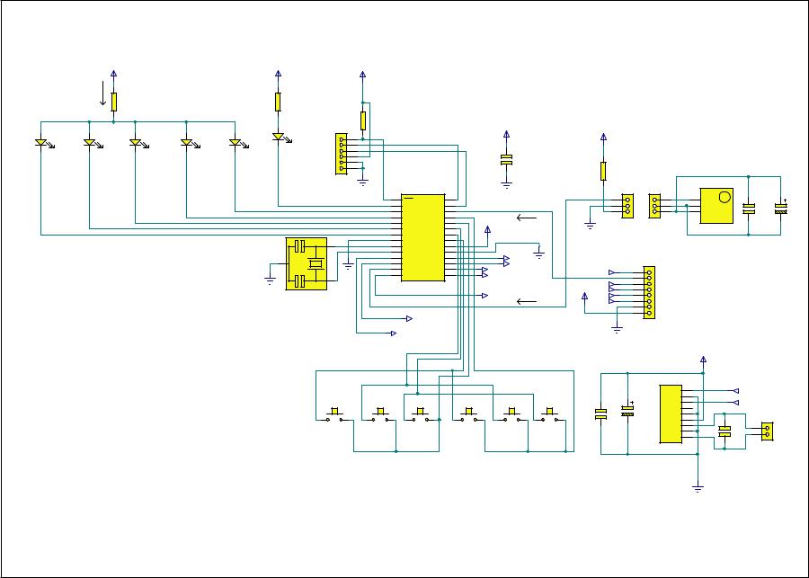
AP14518/1 Microcontroller PCB Schematic (PIC's/Switches/LED's) |
|

Cambridge Azur 340A Intergrated Amplifier
To enhance viewing, please print to A3AP14518/1 Microcontroller PCB Board Layout (Top Side) |
7 |
 Loading...