


AZUR 651R
Your music + our passion
651R/751R
azur
ENGLISH
AV receiver
User’s manual
2
2
Contents
Introduction .........................................................................................................3
Important safety instructions .............................................................................4
Limited warranty .................................................................................................5
Front panel controls............................................................................................6
Rear panel connections......................................................................................8
Zone 2 remote control........................................................................................9
Apple device compatibility ...............................................................................10
Main remote control.........................................................................................10
Loudspeaker connections................................................................................11
Front panel display ...........................................................................................11
Digital audio connections.................................................................................12
Analogue audio connections............................................................................12
HDMI input connections...................................................................................13
Analogue video input connections ..................................................................13
Video output connection (HDMI A & B)...........................................................14
5.1/7.1 direct in ...............................................................................................14
7.1 preamp out.................................................................................................15
Aerial connections ............................................................................................15
FM aerial ...........................................................................................................15
AM loop aerial ...................................................................................................15
Front input connections ...................................................................................15
651R/751R setup............................................................................................16
Speaker setup .............................................................................................16
Front Left and Right speakers....................................................................16
Centre speaker............................................................................................16
Surround Left and Right speakers.............................................................16
Subwoofer....................................................................................................16
Surround Back Left and Right speakers ...................................................16
Front Left and Right Height speakers .......................................................16
Audyssey 2EQ® and Autosetup .................................................................18
Source setup ...............................................................................................21
Audio connection type ................................................................................21
Scaler assign/processing ...........................................................................21
Assigning video inputs ................................................................................21
Video processing settings...........................................................................22
Surround sound modes....................................................................................22
DSP modes........................................................................................................23
Analogue stereo direct .....................................................................................23
Multi channel PCM ...........................................................................................23
USB Audio (751R only).....................................................................................24
Use with PCs .....................................................................................................24
Use with Macs...................................................................................................24
Use with Linux...................................................................................................24
Operating instructions ......................................................................................25
Selecting the source ...................................................................................25
Using the tuner............................................................................................30
Storing stations ...........................................................................................30
Lip sync ........................................................................................................30
Audio Return Channel.................................................................................30
Picture adjustment......................................................................................30
Audio split mode..........................................................................................31
HDMI A and B outputs ................................................................................31
Make sure you register your purchase.
Visit: www.cambridge-audio.com/sts
By registering, you’ll be the first to know about:
G
Future product releases
G
Software upgrades
G
News, events and exclusive offers plus
competitions!
This guide is designed to make installing and using this product
as easy as possible. Information in this document has been
carefully checked for accuracy at the time of printing; however,
Cambridge Audio's policy is one of continuous improvement,
therefore design and specifications are subject to change
without prior notice.
This document contains proprietary information protected by
copyright. All rights are reserved. No part of this manual may be
reproduced by any mechanical, electronic or other means, in
any form, without prior written permission of the manufacturer.
All trademarks and registered trademarks are the property of
their respective owners.
Incognito and Incognito Ready are trademarks of Cambridge
Audio Ltd. All rights reserved.
© Copyright Cambridge Audio Ltd 2012
Manufactured under license from Dolby Laboratories. Dolby,
Pro Logic, and the double-D symbol are trademarks of Dolby
Laboratories.
Manufactured under license under U.S. Patent Nos:
5,956,674; 5,974,380; 6,226,616;6,487,535; 7,212,872;
7,333,929; 7,392,195; 7,272,567 & other U.S. and worldwide
patents issued & pending. DTS-HD, the Symbol, & DTS-HD and
the Symbol together are registered trademarks & DTS-HD
Master Audio is a trademark of DTS, Inc. Product includes
software. © DTS, Inc. All Rights Reserved.
Manufactured under license from Audyssey Laboratories™, Inc.
U.S. and foreign patents pending.
Audyssey 2EQ
®
, Audyssey Dynamic EQ
®
, And Audyssey
Dynamic Volume
®
are registered trademarks and trademark
of Audyssey Laboratories, Inc.
"HDMI","HDMI logo" and "High-Definition Multimedia Interface"
are trademarks or registered trademarks of HDMI Licensing
LLC.
Trigger Outputs............................................................................................31
Bi-amping.....................................................................................................32
Tone/Sub/LFE configuration......................................................................32
Recording.....................................................................................................32
Record 2/Zone 2 Output Select.................................................................33
OSD setup/software version ......................................................................33
Advanced Dolby/DTS adjustments ............................................................33
Dynamic range control................................................................................33
Source Naming............................................................................................33
Using the 651R/751R with an IR repeater system..................................34
Zone 2 setup and use.................................................................................34
DTS-HD speaker re-map .............................................................................36
Custom installation (C.I.) use...........................................................................38
Reset/Back-up memory ...................................................................................38
Troubleshooting ................................................................................................38

The process of setting up the 651R/751R is first to make all the connections
to your speakers and source equipment and then set the unit up via its On-
Screen Display (OSD). There are various settings and adjustments that need
to be made before the 651R/751R can be used.
However before you actually decide which connections to make or perform
any adjustments it is strongly advised that you read through the
‘651R/751R setup’ section of this manual first, starting on page 16.
A lot of explanation is included that will help you to choose the right
connection types for both your sources and TV.
Thank you for purchasing your 651R or 751R AV Receiver. We are confident
that you will enjoy many years of listening pleasure from it. Like all
Cambridge Audio products the 651R/751R adheres to our three core
principles – stunning performance, ease of use and incredible value.
As such, the seven audiophile grade fully discrete class AB amplifiers are
kept as separate as possible from the processing and input stages and
feature a large power supply with a low flux toroidal transformer. This careful
design of the amplifier stages ensures that the 651R/751R can reproduce
the dynamics and scale required for modern movie soundtracks whilst also
being able to reproduce a genuinely musical performance with either stereo
or multichannel music sources.
A full range of HDMI, digital and analogue inputs are fitted. These allow the
connection of suitably equipped Blu-ray players, DVD players, satellite/set-
top boxes and games consoles for decoding into stereo, stereo + sub or
various digital surround formats.
The latest formats are supported including Dolby True HD, Dolby Digital Plus,
DTS-HD Master Audio and DTS-HD High Resolution Audio in 5.1 or 7.1
variants. In particular, support for the true lossless Dolby True HD and DTS-
HD Master Audio formats provides unprecedented audio fidelity from Blu-ray
discs.
Various HDMI 1.4 features are supported including 3D TV and deep-colour
pass-through from suitable sources and Audio Return from TVs with this
feature.
The 651R/751R is also capable of decoding encoded analogue or digital
stereo sources in Dolby Pro Logic® II or IIx and DTS Neo:6, for a convincing
and effective surround experience from a matrix encoded stereo source.
Sophisticated post-processing of 5.1 digital material is also possible with
Dolby Pro Logic IIx or DTS Neo:6 to turn these formats into 7.1.
Alternatively Dolby Pro Logic IIz processing allows height channel generation
from Stereo or 5.1/7.1 material for an alternative 5.1 + Height presentation.
Conventional analogue stereo inputs allow the connection of audiophile CD
players and the like, and an Analogue Stereo Direct mode with no processing
ensures the very best possible stereo reproduction for these.
The 651R/751R also carries a 5.1/7.1 channel analogue input. This feature
allows for the connection of a DVD-Audio or SACD player equipped with a 5.1
output and is compatible with any future external 7.1 audio formats.
As well as the full complement of audio inputs, the 651R/751R performs
Composite, S-Video, Component Video and HDMI switching with transcoding
and scaling (up-converting) of all analogue video to HDMI.
A Zone 2 output allows the Surround Back Amplifiers to be used to power
another Zone if these are not being used for 7.1 output in the Main Zone.
Alternatively if you wish to use all 7.1 channels in the Main Zone a separate
power amplifier and speakers can be connected to the Zone 2 preamp
outputs.
Both Main and Zone 2 remotes are supplied with the 651R/751R.
Audyssey 2EQ
®
, Audyssey Dynamic EQ
®
, Audyssey Dynamic Volume
®
with
Autosetup help achieve the best performance in your particular room and
with your speaker setup.
An RS232 port and IR Emitter In also make it easy to integrate the
651R/751R into a Custom Install situation.
The 651R and 751R share all the extensive features above. The 751R differs
from the 651R by being more powerful, having one extra HDMI 1.4 input on
the rear and an additional HDMI 1.3 In on the front panel. The 751R also
features Anagram Technologies ATF up-sampling on all channels.
This is performed by a third DSP (Digital Signal Processor) over the two used
in the 651R which converts all digital audio to 24-bit/192kHz with
comprehensive jitter suppression before conversion by the DACs.
Finally the 751R also features a 24 Bit Asynchronous USB Audio input
capable of up to 24-bit/192kHz Audio from Mac and PC.
All this proprietary engineering is housed within our low resonance,
acoustically damped chassis. An Azur Navigator remote control is also
provided, giving full remote control of your AV receiver in an attractive and
easy to use handset.
651R/751Razur
3
Introduction
Before connecting
ENGLISH
Remember your 651R/751R can only be as good as the system it is
connected to. Please do not compromise on your source equipment, speaker
package or video and audio cabling. Naturally we particularly recommend
Blu-ray players, digital and analogue iPod docks, Network and CD players
from the Cambridge Audio Azur range, which have been designed to the
same exacting standards as our receivers. Your dealer can also supply
excellent quality Cambridge Audio interconnects to ensure your system
realises its full potential.
Thanks for taking the time to read this manual, we do recommend you keep
it for future reference.
Matthew Bramble
Cambridge Audio Technical Director
and the 651R/751R design team
4
For your own safety please read the following important safety instructions
carefully before attempting to connect this unit to the mains power supply.
They will also enable you to get the best performance from and prolong the
life of the unit:
1. Read these instructions.
2. Keep these instructions.
3. Heed all warnings.
4. Follow all instructions.
5. Do not use this apparatus near water.
6. Clean only with a dry cloth.
7. Do not block any ventilation openings. Install in accordance with the
manufacturer's instructions.
8. Do not install near any heat sources such as radiators, heat registers,
stoves, or other apparatus (including amplifiers) that produce heat.
9. Do not defeat the safety purpose of the polarized or grounding-type plug.
A polarized plug has two blades with one wider than the other. A
grounding-type plug has two blades and a third grounding prong. The
wide blade or the third prong are provided for your safety. If the provided
plug does not fit into your outlet, consult an electrician for replacement
of the obsolete outlet.
10. Protect the power cord from being walked on or pinched, particularly at
plugs, convenience receptacles and the point where they exit from the
apparatus.
11. Only use attachments/accessories specified by the manufacturer.
12. Use with only the cart, stand, tripod, bracket, or table
specified by the manufacturer, or sold with the apparatus.
When a cart is used, use caution when moving the cart/
apparatus combination to avoid injury from tip-over.
13. Unplug this apparatus during lightning storms or when unused for long
periods of time.
14. Refer all servicing to qualified service personnel. Servicing is required
when the apparatus has been damaged in any way, such as the power-
supply cord or plug having been damaged, liquid has been spilled or
objects have fallen into the apparatus, the apparatus has been exposed
to rain or moisture, does not operate normally, or has been dropped.
WARNING
– To reduce the risk of fire or electric shock, do not expose this unit to rain
or moisture.
– Batteries (battery pack or batteries installed) shall not be exposed to
excessive heat such as sunshine, fire or the like.
The unit must be installed in a manner that makes disconnection of the
mains plug from the mains socket outlet (or appliance connector from the
rear of the unit) possible. Where the mains plug is used as the disconnect
device, the disconnect device shall remain readily operable. Only use the
mains cord supplied with this unit.
Please ensure there is ample ventilation (at least 10cm clearance all round).
Do not put any objects on top of this unit. Do not situate it on a rug or other
soft surface and do not obstruct any air inlets or outlet grilles. Do not cover
the ventilation grilles with items such as newspapers, tablecloths, curtains,
etc.
This unit must not be used near water or exposed to dripping or splashing
water or other liquids. No objects filled with liquid, such as vases, shall be
placed on the unit.
Important safety instructions
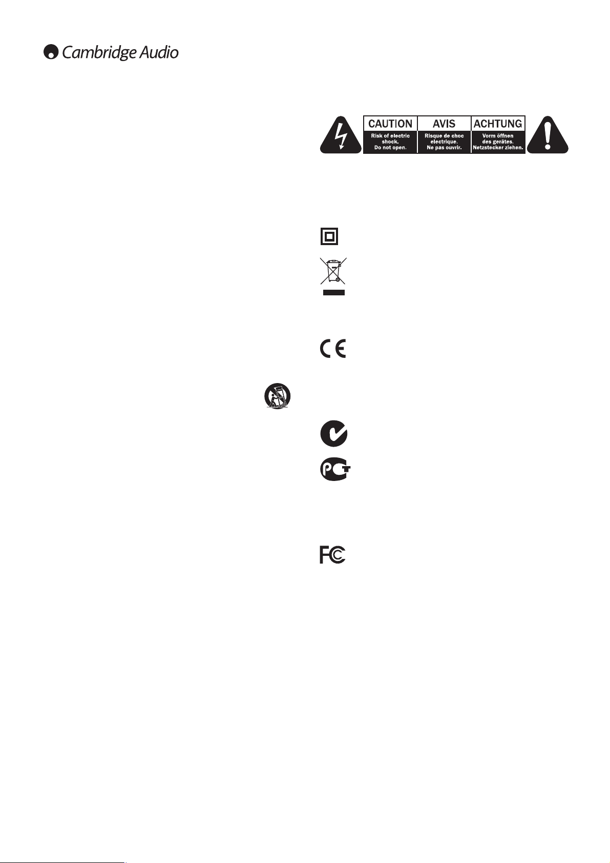
The lightning flash with the arrowhead symbol within an equilateral triangle
is intended to alert the user to the presence of un-insulated ‘dangerous
voltage’ within the product’s enclosure that may be of sufficient magnitude
to constitute a risk of electric shock to persons.
The exclamation point within an equilateral triangle is intended to alert the
user to the presence of important operating and maintenance instructions in
the service literature relevant to this appliance.
The symbol on this product indicates that it is of CLASS II (double
insulated) construction.
WEEE symbol
The crossed-out wheeled bin is the European Union symbol for
indicating separate collection for electrical and electronic
equipment. This product contains electrical and electronic
equipment which should be reused, recycled or recovered and
should not be disposed of with unsorted regular waste. Please return the unit
or contact the authorised dealer from whom you purchased this product for
more information.
CE mark
This product complies with European Low Voltage (2006/95/EC),
Electromagnetic Compatibility (2004/108/EC) and
Environmentally-friendly design of Energy-related Products (2009/125/EC)
Directives when used and installed according to this instruction manual. For
continued compliance only Cambridge Audio accessories should be used
with this product and servicing must be referred to qualified service
personnel.
C-Tick mark
This product meets the Australian Communications Authority’s
Radio communications and EMC requirements.
Gost-R Mark
This product meets Russian electronic safety approvals.
FCC regulations
NOTE: THE MANUFACTURER IS NOT RESPONSIBLE FOR ANY RADIO OR TV
INTERFERENCE CAUSED BY UNAUTHORIZED MODIFICATIONS TO THIS
EQUIPMENT. SUCH MODIFICATIONS COULD VOID THE USER AUTHORITY TO
OPERATE THE EQUIPMENT.
This equipment has been tested and found to comply with the
limits for a Class B digital device, pursuant to Part 15 of the FCC
Rules. These limits are designed to provide reasonable protection
against harmful interference in a residential installation. This equipment
generates, uses and can radiate radio frequency energy and, if not installed
and used in accordance with the instructions, may cause harmful
interference to radio communications. However, there is no guarantee that
interference will not occur in a particular installation.
If this equipment does cause harmful interference to radio or television
reception, which can be determined by turning the equipment off and on, the
user is encouraged to try to correct the interference by one or more of the
following measures:
- Re-orient or relocate the receiving antenna.
- Increase the separation between the equipment and receiver.
- Connect the equipment into an outlet on a circuit different from that to
which the receiver is connected.
- Consult the dealer or an experienced radio/TV technician for help.

651R/751Razur
5
Cambridge Audio warrants this product to be free from defects in materials
and workmanship (subject to the terms set forth below). Cambridge Audio
will repair or replace (at Cambridge Audio's option) this product or any
defective parts in this product. Warranty periods may vary from country to
country. If in doubt consult your dealer and ensure that you retain proof of
purchase.
To obtain warranty service, please contact the Cambridge Audio authorised
dealer from which you purchased this product. If your dealer is not equipped
to perform the repair of your Cambridge Audio product, it can be returned by
your dealer to Cambridge Audio or an authorised Cambridge Audio service
agent. You will need to ship this product in either its original packaging or
packaging affording an equal degree of protection.
Proof of purchase in the form of a bill of sale or receipted invoice, which is
evidence that this product is within the warranty period, must be presented
to obtain warranty service.
This Warranty is invalid if (a) the factory-applied serial number has been
altered or removed from this product or (b) this product was not purchased
from a Cambridge Audio authorised dealer. You may call Cambridge Audio or
your local country Cambridge Audio distributor to confirm that you have an
unaltered serial number and/or you purchased from a Cambridge Audio
authorised dealer.
This Warranty does not cover cosmetic damage or damage due to acts of
God, accident, misuse, abuse, negligence, commercial use, or modification
of, or to any part of, the product. This Warranty does not cover damage due
to improper operation, maintenance or installation, or attempted repair by
anyone other than Cambridge Audio or a Cambridge Audio dealer, or
authorised service agent which is authorised to do Cambridge Audio
warranty work. Any unauthorised repairs will void this Warranty. This
Warranty does not cover products sold AS IS or WITH ALL FAULTS.
REPAIRS OR REPLACEMENTS AS PROVIDED UNDER THIS WARRANTY ARE
THE EXCLUSIVE REMEDY OF THE CONSUMER. CAMBRIDGE AUDIO SHALL
NOT BE LIABLE FOR ANY INCIDENTAL OR CONSEQUENTIAL DAMAGES FOR
BREACH OF ANY EXPRESS OR IMPLIED WARRANTY IN THIS PRODUCT.
EXCEPT TO THE EXTENT PROHIBITED BY LAW, THIS WARRANTY IS EXCLUSIVE
AND IN LIEU OF ALL OTHER EXPRESS AND IMPLIED WARRANTIES
WHATSOEVER INCLUDING, BUT NOT LIMITED TO, THE WARRANTY OF
MERCHANTABILITY AND FITNESS FOR A PRACTICAL PURPOSE.
Some countries and US states do not allow the exclusion or limitation of
incidental or consequential damages or implied warranties so the above
exclusions may not apply to you. This Warranty gives you specific legal rights,
and you may have other statutory rights, which vary from state to state or
country to country.
For any service, in or out of warranty, please contact your dealer.
Plug Fitting Instructions (UK Only)
The cord supplied with this appliance is factory fitted with a UK mains plug fitted
with a 5 amp fuse inside. If it is necessary to change the fuse, it is important that
a 5 amp one is used. If the plug needs to be changed because it is not suitable for
your socket, or becomes damaged, it should be cut off and an appropriate plug
fitted following the wiring instructions below. The plug must then be disposed of
safely, as insertion into a mains socket is likely to cause an electrical hazard.
Should it be necessary to fit a 3-pin BS mains plug to the power cord the wires
should be fitted as shown in this diagram. The colours of the wires in the mains
lead of this appliance may not correspond with the coloured markings identifying
the terminals in your plug. Connect them as follows:
The wire which is coloured BLUE must be
connected to the terminal which is marked
with the letter ‘N’ or coloured BLACK.
The wire which is coloured BROWN must be
connected to the terminal which is marked
with the letter ‘L’ or coloured RED.
The wire which is coloured GREEN/YELLOW
must be connected to the terminal which is
marked with the letter ‘E’ or coloured GREEN.
If your model does not have an earth wire, then disregard this instruction.
If a standard 13 amp (BS 1363) plug is used, a 5 amp fuse must be fitted, or if
any other type of plug is used a 5 amp fuse must be fitted, either in the plug or
adaptor, or on the distribution board.
ENGLISH
Limited warranty
Ventilation
IMPORTANT – The unit will become hot when in use. Do not stack multiple units
on top of each other. Do not place in an enclosed area such as a bookcase or in a
cabinet without sufficient ventilation.
Ensure that small objects do not fall through any ventilation grille. If this happens,
switch off immediately, disconnect from the mains supply and contact your dealer
for advice.
Positioning
Choose the installation location carefully. Avoid placing it in direct sunlight or
close to a source of heat. No naked flame sources, such as lighted candles,
should be placed on the unit. Also avoid locations subject to vibration and
excessive dust, cold or moisture. The unit can be used in a moderate climate.
This unit must be installed on a sturdy, level surface. Do not place in a sealed
area such as a bookcase or in a cabinet. Any space open at the back (such
as a dedicated equipment rack) is fine, however. Do not place the unit on an
unstable surface or shelf. The unit may fall, causing serious injury to a child
or adult as well as serious damage to the product. Do not place other
equipment on top of the unit.
Due to stray magnetic fields, turntables or CRT TVs should not be located
nearby due to possible interference.
Electronic audio components have a running in period of around a week (if
used several hours per day). This will allow the new components to settle
down and the sonic properties will improve over this time.
Power sources
The unit should be operated only from the type of power source indicated on
the marking label. If you are not sure of the type of power-supply to your
home, consult your product dealer or local power company.
This unit can be left in Standby mode when not in use and will draw <0.5W
in this state. To turn the unit off, switch off at the rear panel. If you do not
intend to use this unit for a long period of time, unplug it from the mains
socket.
Overloading
Do not overload wall outlets or extension cords as this can result in a risk of
fire or electric shock. Overloaded AC outlets, extension cords, frayed power
cords, damaged or cracked wire insulation and broken plugs are dangerous.
They may result in a shock or fire hazard.
Be sure to insert each power cord securely. To prevent hum and noise, do not
bundle the interconnect leads with the power cord or speaker leads.
Cleaning
To clean the unit, wipe its case with a dry, lint-free cloth. Do not use any
cleaning fluids containing alcohol, ammonia or abrasives. Do not spray an
aerosol at or near the unit.
Battery disposal
Batteries may contain substances harmful to the environment. Please
dispose of any discharged batteries with due consideration and in
accordance with local environmental/electronic recycling guidelines.
Loudspeakers
Before making any connections to loudspeakers, make sure all power is
turned off and only use suitable interconnects.
Servicing
These units are not user serviceable. Never attempt to repair, disassemble
or reconstruct the unit if there seems to be a problem. A serious electric
shock could result if this precautionary measure is ignored. In the event of a
problem or failure, please contact your dealer.
IMPORTANT
If the unit is run at a very high level, a sensor will detect a temperature rise and
show "PROTECTION OVERLOAD" on the display. The unit will then go into Standby
mode. It cannot be switched on again until the temperature has fallen to a more
normal level.
1 2 3 4 5
17 18 19 20 21
6
9 10 11 12 13 14 15 16
22
23 24
25
26
7 8
66
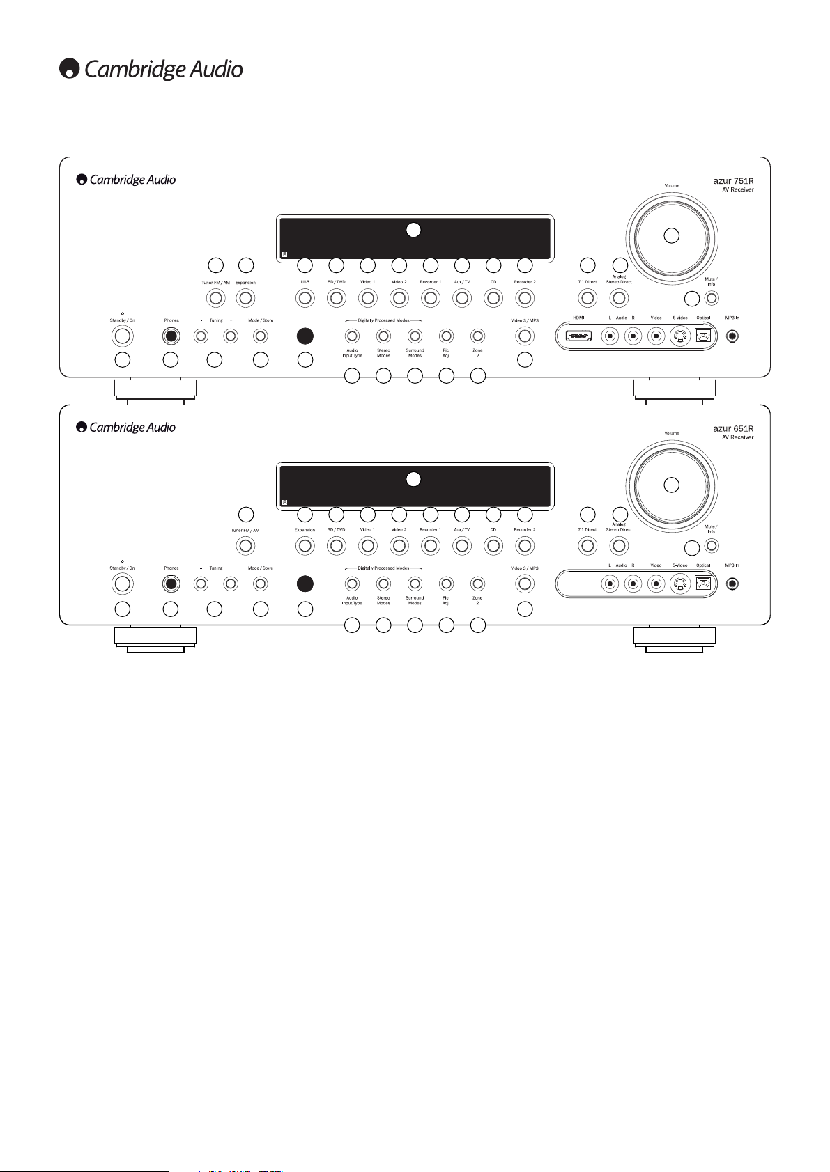
Front panel controls
1 Standby/On
Switches the unit between Standby mode (indicated by a dim power LED)
and On (indicated by a bright power LED). Standby is an eco-friendly <0.5W
low power mode. The unit may be left in Standby mode when not in use.
2 Phones
Allows for the connection of stereo headphones with a 6.35mm/¼" Jack
plug. Headphones with an impedance of between 32 and 600 ohms are
recommended.
Note: Plugging in headphones will automatically mute the main and pre-amp
outputs and select a Dolby Headphones output to be created for headphone
use.
3 Tuning +/-
Used to tune FM/AM frequencies and skip presets for the built-in Tuner.
4 Mode/Store
Press to cycle between Tuner modes. Press and hold for storing presets
(refer to the ‘Operating Instructions’ of this manual for more information).
5 Infrared sensor
Receives IR commands from the supplied remote control. A clear,
unobstructed line of sight between the remote control and the sensor is
required.
6 Display
Displays the status of the unit.
7 Tuner FM/AM
Press to select the tuner. Once in Tuner mode press to switch between FM
and AM modes.
Note: The 651R/751R remembers the audio and video input type and
processing mode for each individual source input. These are recalled each
time a source is selected.
8 Expansion
Press to select an optional expansion source module connected to the
Expansion port at the back of the unit.
9 USB (751R only)
Press to select the USB Audio source connected to the USB input at the back.
10 BD/DVD
Press to select the source equipment connected to the BD/DVD input.
11 Video 1
Press to select the source equipment connected to the Video 1 input.
12 Video 2
Press to select the source equipment connected to the Video 2 input.
13 Recorder 1
Press to select the source equipment connected to the Recorder 1 input.
14 Aux/TV
Press to select the source equipment connected to the Aux input.
With ARC enabled (see later section), press again to select Audio Return
Channel from a suitable TV.
15 CD
Press to select the source equipment connected to the CD input.
16 Recorder 2
Press to select the source equipment connected to the Recorder 2 input.
1 2 3 4 5
17 18 19 20 21
6
8 10 11 12 13 14 15 16
22
23 24
25
26
7

651R/751Razur
7
ENGLISH
17 Audio input type
Press this button to select between analogue, digital (optical/coaxial) or HDMI
input types as the source of the audio for the currently selected source input.
The choices available depend on the inputs that have been assigned to that
source, see later section.
18 Stereo modes
Press to listen to a source in either digitally processed stereo or stereo and
sub modes.
19 Surround modes
Press to select Dolby Digital or DTS surround modes (with suitably encoded
digital source material), or various Dolby Pro Logic II/IIx/IIz, DTS Neo:6
modes for matrix encoded analogue or digital material.
Post-processing of digital surround types with Dolby Pro Logic IIx/IIz or Neo:6
is also possible. See later decode mode tables for details.
20 Picture adjustment
Press to select various picture adjustments for sources that have the Scaler
set to Process only (see ‘Source setup’ section in the manual). An
adjustment bar will appear on the TV for the current item (Brightness,
Contrast etc.) Press the Pic. Adj. button again to move to the next item.
Use the volume knob to adjust the level of the current parameter.
Note: For source material, the scaler cannot process (such as deep colour or
3D content). Pic. Adj. will have no effect.
This button is also used to change the scaler output resolution. Press and
hold the button for 10 seconds and the current output resolution will appear
on the 651R/751Rs front panel display. Keep holding the button down and
the 651R/751R will change to the next available resolution and show it on
the front panel display. See later section.
21 Zone 2
Press to choose Zone 2 and display its status. The next source change or
volume adjustment will now affect Zone 2. See later section of this manual
for more information.
22 Video 3/MP3
Press to select the source equipment connected to the Video 3 or MP3 input
(if a device is plugged into its 3.5mm mini-jack input).
Note: The L audio input is also used for the supplied auto setup microphone.
Refer to the ‘Auto setup’ section of this manual for more information.
For the 751R only
A HDMI 1.3 input is also available.
23 7.1 Direct
Press to select a 7.1 or 5.1 source (DVD-A or SACD player etc) connected to
the 7.1 Direct In sockets.
24 Analogue stereo direct
Press to listen to the analogue inputs for the current source directly with no
analogue to digital conversion or DSP processing for highest possible stereo
sound quality.
25 Volume
Use to increase/decrease the level of the sound from the outputs of the
651R/751R.
26 Mute/Info
Press to mute the sound from the main and pre-amp outputs of the
651R/751R. Press again to cancel mute.
Note: Selecting a new source always cancels mute.
Press and hold to re-display the current decoding mode.
8
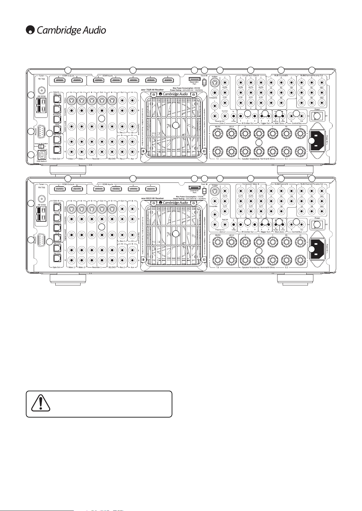
Rear panel connections
1. FM/AM antennas
All tuner antenna connections are made here. Refer to the ‘Antenna
Connections’ section of this manual for more information.
2. RS232C
Used for control of the 651R/751R in Custom Install situations. A full
protocol is available for the 651R/751R on our website.
3. USB interface (751R only)
A USB B type socket is fitted to the 751R to enable the playback of audio
from a personal computer running either Microsoft Windows or Apple Mac OS
X operating systems. Some distributions of Linux are also suitable.
Note: Always use a high quality USB connection cable certified as USB Hi-
Speed. USB cable connections longer than 3m may result in inconsistent
audio performance.
See later section for full details on USB audio.
4. Opto inputs/outputs
Toslink digital inputs for Video 1, Rec 1, BD/DVD and CD sources and also
two Toslink digital outputs for Rec 1 and 2.
5. A/B HDMI outputs
Via the On Screen Display A, B or A and B outputs can be selected (for
connection to two TVs or a TV and a projector for instance).
When both outputs are selected both show the same content.
HDMI A also supports an HDMI 1.4 Audio Return Channel from TVs that also
support this feature.
This allows audio from the TVs own in built tuner to be received by the
651/751R. See later TV-ARC section for details.
6. HDMI
HDMI inputs compatible with the HDMI 1.4 standard. By Default the HDMI
inputs are assigned to BD/DVD, Video 1 and Video 2, with the 4th input
unassigned.
These inputs can be freely assigned, see later section on assigning video
inputs.
All video inputs whether analogue or HDMI are transcoded and output via the
HDMI outputs.
7. Video 1/2, Recorder 1/2, BD/DVD, CD and Aux
Please refer to the connection diagrams later in this manual for more
information on these inputs and outputs.
8. Heat tunnel vent grille
Allows cooling of internal circuitry via the 651R/751R’s proprietary X-TRACT
heat tunnel. DO NOT OBSTRUCT!
1
2
3
4
7
8
9 10 11 12
20
20
19
15 16 17 18
13 145
1
2
4
7
8
9 10 11 12
21
20
19
15 16 17 18
13 145
6
6
Always turn the Volume to minimum, or turn the
751R off before plugging/unplugging cables to the
USB input or whilst booting up/shutting down your
PC/Mac.
651R/751Razur
9
ENGLISH
9. Expansion port
For connection to optional Expansion Source Modules as they become
available. Contact your Cambridge Audio dealer for details.
10. Front IR switch
Turns the units built-in IR receiver reception on/off if it is desired to use an
IR repeater system plugged into the rear Main Zone IR Emitter Input instead.
11. Zone 2
Independant stereo audio and analogue video outputs to a second Zone (i.e.
a room or area separate from the main area. The IR Emitter input allows
control of the 651R/751R and its sources remotely from that Zone. See
Zone 2 section in this manual for details.
12. Component video inputs
By default the component inputs are unassigned, these inputs can be freely
assigned, see later section on assigning video inputs.
Note: The preferred connection method for video inputs is always Composite
Video, then S-Video, then Component Video, then HDMI in ascending order
of quality (HDMI being the highest quality). HDMI and Component Video
sources often also support Progressive Scan which gives better picture
quality if supported by both your BD/DVD player and TV.
13. Multi-Channel In
Connect to the output terminals of a DVD-A, SACD player or other 5.1/7.1
analogue source.
14. Multi-Channel preamp out
Connect to the 5.1/7.1 channel input terminals of another amplifier system,
separate power amps, subwoofer or active loudspeakers. Two subwoofer
outputs are supported with both receiving the same signal.
15. IR emitter out
Use with IR Emitters to control the sources from Zone 2 remotely. See later
section.
16. Trigger out
12V triggers for controlling external amplifiers, curtains, motorised screens
or other such equipment. See later section.
17. Main zone IR emitter in
Allows modulated IR commands from multi-room systems or IR repeater
systems to be received by the 651R/751R.
18. Control bus
In - Allows un-modulated commands from multi-rooms systems or other
components to be received by the unit. (Main Zone only)
Out - Loop out for control bus commands to another unit.
Note: The Emitter inputs are not looped out of the Control Bus output.
19. Power on/off
Switches the unit on and off.
20. Mains power lead
Once you have completed all connections, plug the AC power lead into an
appropriate mains socket. The AV receiver is now ready for use.
21. Speaker terminals
Connect to loudspeakers with an impedance of between 4-8 ohms. 7.1, 5.1
or less connections can be made.
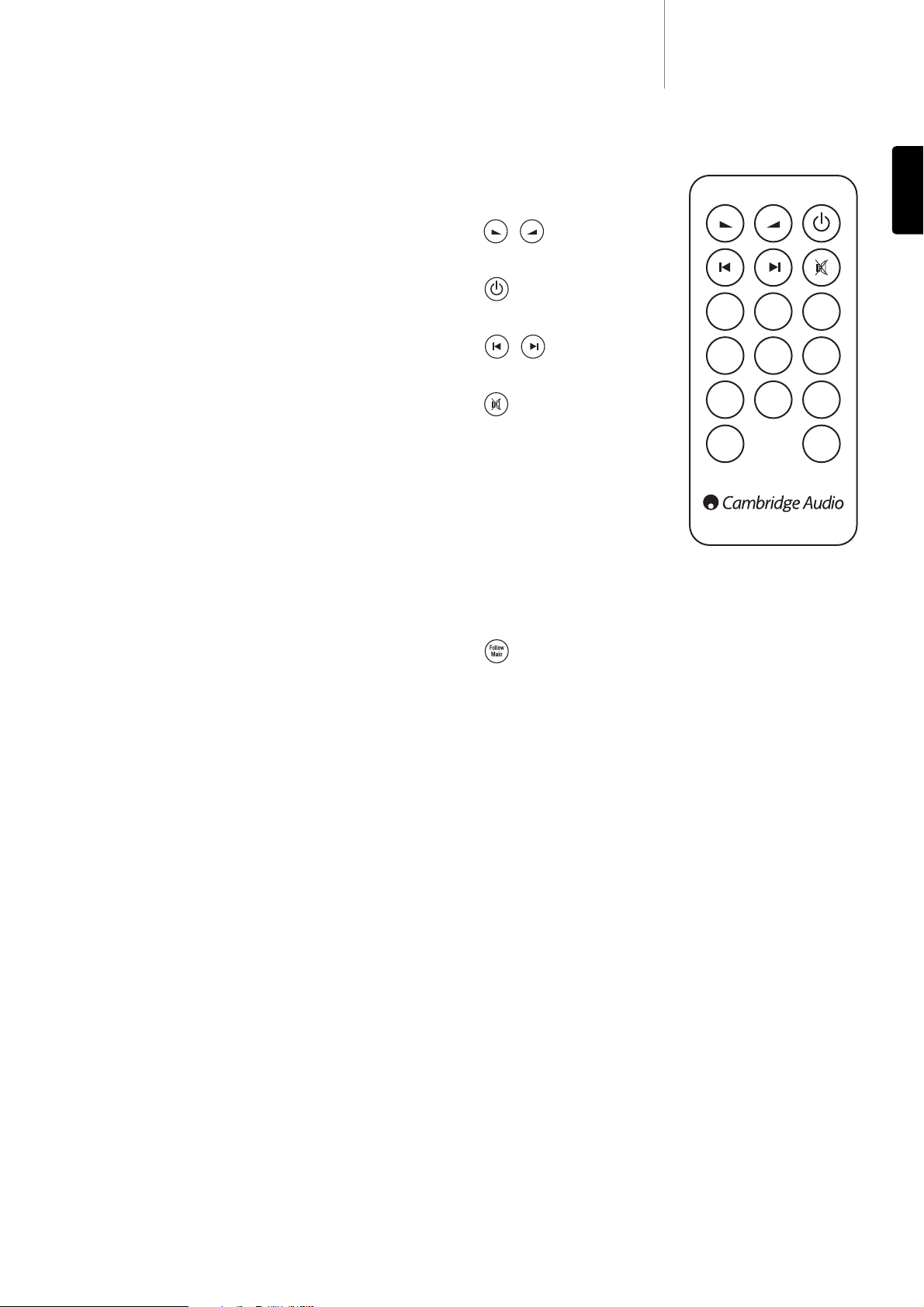
The Zone 2 remote only affects the
Zone two outputs. It has no affect on
the operation of the main zone.
Volume
Use to increase/decrease the level of
sound in Zone 2.
Standby
Switches Zone 2 between Standby
mode and On.
Skip
Skips up or down the tuner presets
that have been set.
Mute
Mutes the audio output in Zone 2.
Press again to cancel mute.
Sources
Press the corresponding button to
change the source for Zone 2.
Pressing the Tuner AM/FM button a
second time toggles between AM and
FM modes.
Zone 2 is analogue by nature and
only sources with audio/video
connections (as well as digital ones)
can be used in Zone 2.
Note: It is not possible to directly select TV/ARC or USB in Zone 2 as these
are digital only sources.
Follow Main
Sends an Analogue 2 Channel down-mix (L+C, R+C) of the source selected in
the Main Zone to Zone 2.
This is useful if you want to listen to the same thing in both Zones (for a party
perhaps) or wish to hear digital or surround sources in Zone 2 which cannot
be directly selected by Zone 2.
Because the downmix is created from the main zones decoded output any
source selected in the main zone including those connected by digital
(opto/coax) and HDMI inputs can be sent to Zone 2 in this way.
Zone 2 Remote
Tuner
AM/FM
BD
DVD
Vid 3
MP3
Video 1
Aux
Video 2
Exp
Follow
Main
Rec 1
Rec 2
CD
Zone 2 remote control
10
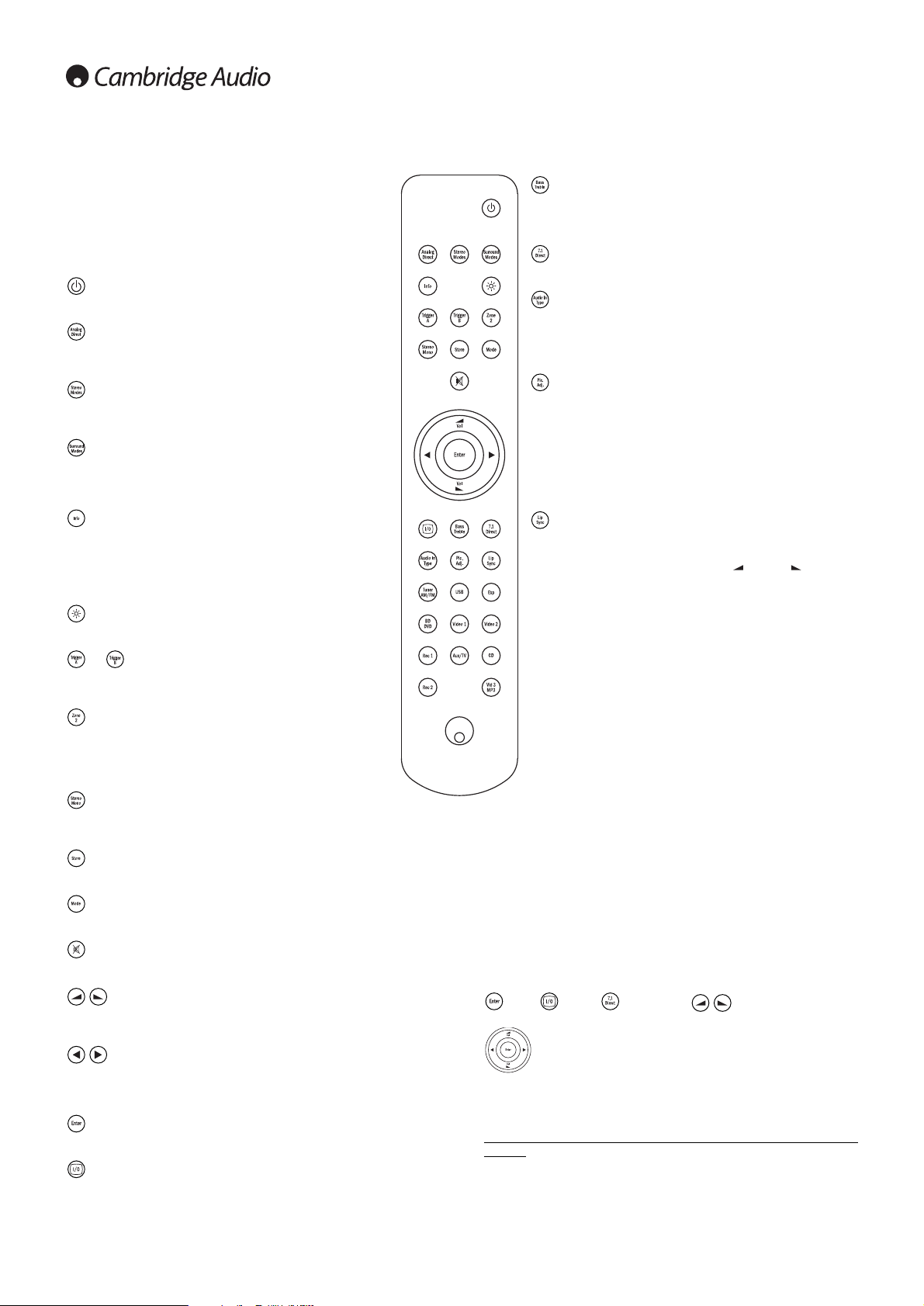
Main remote control
Bass/Treble
Press for bass/treble adjustment, using the Volume up/down
buttons. Note: Bass/Treble is bypassed in analogue stereo direct
and 7.1 direct modes.
7.1 direct
Selects the 5.1/7.1 direct input.
Audio in type
Switches the audio between the types available for the current
source. Depending on the source selected and whether you have
assigned an HDMI input to it, Analogue, Digital and HDMI can be
available.
Picture adjustment
Press to select various picture adjustments for sources that have
the Scaler set to Process only.
An adjustment bar will appear on the TV for the current item
(Brightness, Contracts etc.) Press the Pic. Adj. button again to move
to the next item. Use the volume buttons to make the adjustments.
Pressing and holding Pic. Adj. when the OSD is active switches the
active HDMI output. See later ‘HDMI A and B outputs’ section.
Lip sync
Press to activate and adjust the lip sync delay function if the audio
and video appear out of sync. While the Lip sync delay status is
shown on the units display, use the Vol and Vol buttons to
adjust the delay time. Adjusting the value to zero causes lip sync
delay to be turned off. See later section in this manual.
Tuner AM/FM, USB (751R only), Exp, BD/DVD,
Video 1, Video 2, Rec 1, Aux/TV, CD, Rec 1, Vid
3/MP3
Press the corresponding button to change the input source.
Pressing the Tuner AM/FM button a second time toggles between
AM and FM modes.
Pressing the Aux/TV button a second time if ARC is enable (see
later section) selects TV-ARC (Audio Return Channel).
The above button descriptions are naturally brief. Please refer to
the ‘Operating Instructions’ section of this manual for more
information on the relevant functions implemented.
Apple device compatibility
The Azur 651R/751R Navigator remote control can control the basic
functions of Apple devices such as Apple TV and Apple’s
iPod/iPhone/iPad range when docked in a Cambridge Audio or Apple
dock.
Press and hold the source button that corresponds to the input that the
Apple product is connected to whilst also pressing one of the buttons
below.
The functions are slightly different depending on the Apple product.
Enter, Menu, Play/Pause, Used to control volume
and/or navigate menus.
Used to navigate menus or Skip/Scan depending on Apple
product used.
In addition, the Azur remote can be paired with up to six specific Apple
devices using any of the six source buttons. This can be useful if you have
more than one Apple product.
For more information on pairing refer to your Apple device’s instruction
manual.
Pairing – To pair with an Apple device, press and hold the required source
button along with the MODE button for six seconds. Some devices like
Apple TV have visual indication once pairing is achieved.
Un-pairing – To un-pair an Apple device, press and hold any of the source
buttons along with the STEREO MONO button for six seconds.
The 651R/751R is supplied with an Azur Navigator remote control.
Insert the supplied AAA batteries to use. For full details of the
various adjustment functions available from the remote, refer to
the later sections of this manual.
This remote can be used in the Main Zone or Zone 2 (via an IR
repeater system) and will automatically affect only the Zone in
which it is used.
Standby/On
Switches the unit between Standby mode and On.
Analogue direct
Directly selects a stereo analogue input for the current source with
no A/D or D/A conversion or DSP processing.
Stereo modes
Selects Stereo or Stereo + Sub modes for Analogue or Digital
sources (digitally processed).
Surround modes
Selects digital surround processing modes and various matrix
encoded surround processing modes for analogue or digital
sources (digitally processed).
Info
Press to view the current source material and decoding mode.
Press again whilst the current decoding mode is scrolling (as long
as mute is not on) to display the incoming sample rate. When
listening to FM with RDS, press to cycle round various RDS
information modes.
Bright
Adjust the backlight of the front panel display; bright, dim or off.
& Trigger A/B
Toggle On and Off the Trigger outputs. See trigger section for
details and setup.
Zone 2
Selects Zone 2 and displays its status on the display. The next
source change, Standby/On or volume control commands will
affect Zone 2 instead of the Main Zone. See Zone 2 section for
details.
Stereo mono
When listening to FM, press to alternate between stereo and mono
modes.
Store
Press to store the current frequency as a preset when in Tuner mode.
Mode
Press to select Auto/Manual or Preset tuning when in Tuner mode.
Mute
Mutes the audio on the AV Receiver. Press again to cancel mute.
Volume
Increase or decrease the volume of the AV receiver output. Also used as
up/down in the OSD setup menus.
Tune / Left & Right
Press the right arrow to increase tuner frequency/change preset. Press the
left arrow to decrease tuner frequency/change preset. Also used to scroll
left/right in the OSD setup menus.
Enter
Used in the OSD setup menus.
On-screen display (OSD)
Press to turn on and off the on-screen setup menus for display on your
monitor/screen.
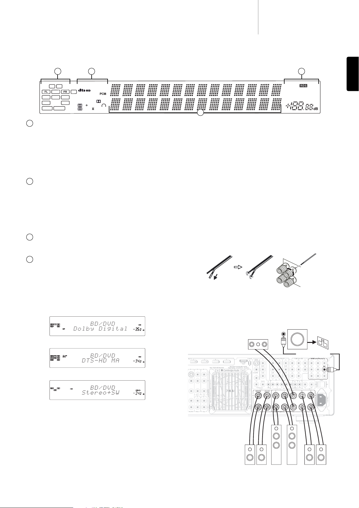
Output channel indicators
Shows the currently active channels depending on decoding mode and
source material. Icons lit indicate channels being output by the 651R/751R.
Z2
Indicates Zone 2 is active (on).
Room EQ
Indicates Audyssey 2QE
®
is enabled.
Decoding mode indicators (PCM, Dolby Digital, DTS
etc)
Shows the current decoding mode, Dolby Digital, DTS etc. In conjunction with
the Output Channel indicators these give full details of the current
processing mode.
Direct indicator
Lights when the 651R/751R is in a Direct mode - Analogue Stereo Direct or
7.1 Direct.
Main information display
Shows the current source selected, also the surround mode and station
name/frequency when in tuner mode etc.
Mode icons
HDMI
Indicates the current source audio input type is HDMI.
Digital/Analogue indicators
Indicates whether the current source audio input type is Digital (S/P
DIF/Toslink) or Analogue.
Display examples
Indicates a 5.1 Dolby Digital source being played back as 5.0 (Sub off).
Indicates a 7.1 playback of DTS-HD Master material.
Indicates a 2.1 output created in the digital domain from analogue input
material.
1
2
3
4
651R/751Razur
11
ENGLISH
Front panel display
SL SW SR
SBL SBR
DIRECT
Bi AMP
RoomEQ
LH RH
96/24
Dynamic
MSTR
D TrueHD
EXPL
Vol
xz
Audyssey
EQ
ES
HR
Exp
Neo:6 X
Z2
C
ANA LOG DIGITAL
MUTING
USB
TUNED FM STEREO
AUTO
HDMI
2 4
3
To avoid damaging the speakers with a sudden high-level signal, be sure to
switch the power off before connecting the speakers. Check the impedance
of your speakers. Speakers with an impedance of between 4 and 8 ohms
(each) are recommended.
The coloured speaker terminals are positive (+) and the black speaker
terminals are negative (-). Make sure correct polarity is maintained at each
speaker connector or the sound can become weak and “phasey” with little
bass.
Prepare the speaker cords for connection by stripping off approximately
10mm (3/8”) or less (no more than 10mm, as this could cause a short-
circuit) of the outer insulation. Twist the wire tightly together so there are no
loose ends. Unscrew the speaker terminal knob, insert the speaker cable,
tighten the knob and secure the cable.
Note: All connections are made via loudspeaker cable, except if using an
active subwoofer which would be connected via a standard RCA phono cable.
Banana Plugs (4mm standard) connected to the speaker cable are
recommended for direct insertion into the speaker terminals.
Please refer to the ‘Speaker Configuration’ section of this manual for more
information on 5.1 and 7.1 speaker setups.
Loudspeaker connections
Front
speakers
Surround
speakers
Centre speaker
Surround back
speakers
Powered subwoofer
Phono/RCA cable
1
12
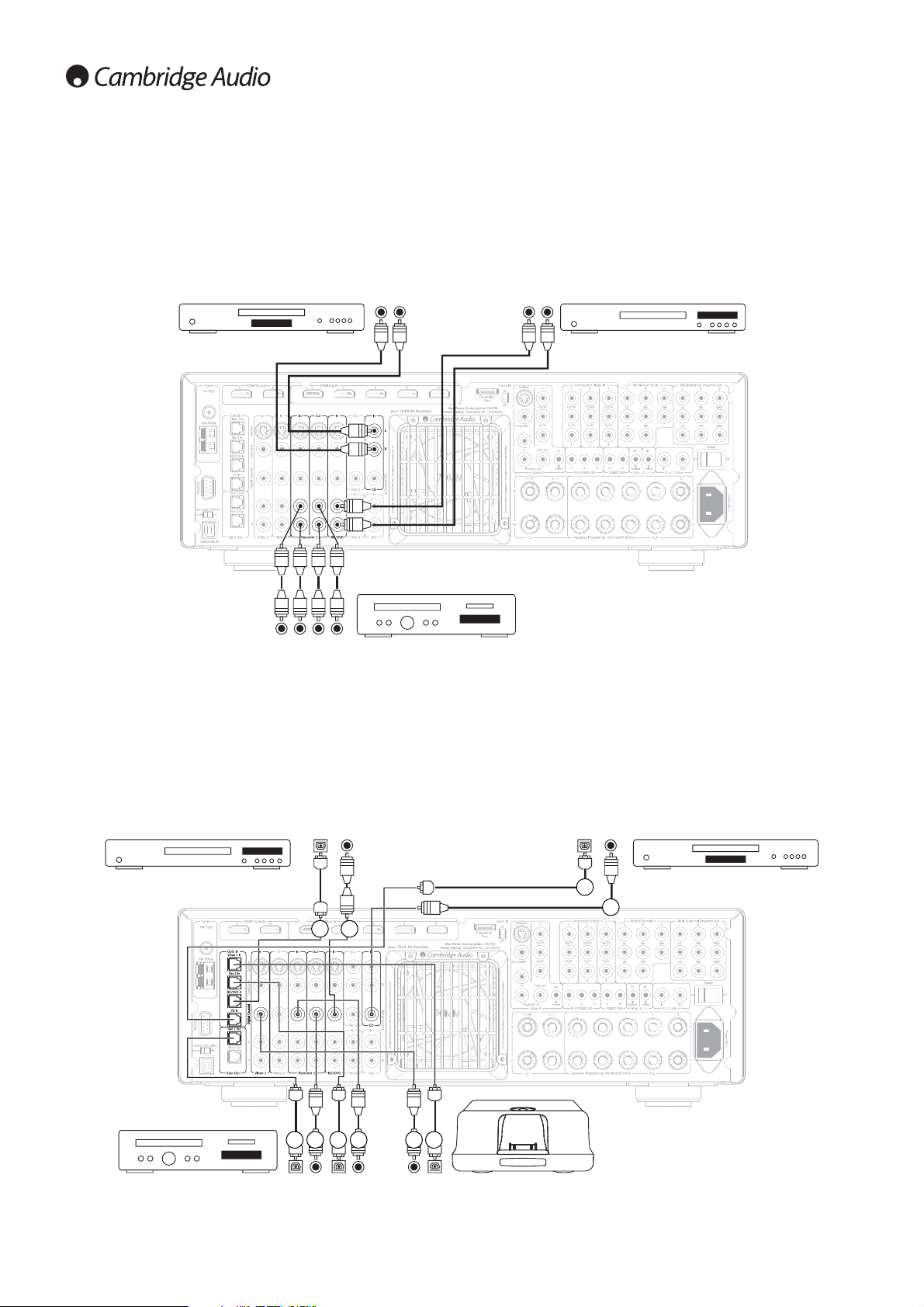
Analogue audio connections
Note: Do not plug in the mains power lead or turn the unit on until all
connections have been made.
Connect to source equipment using stereo phono cables (stereo 2RCA-
2RCA). Tape/MD/CDR recorder/players require two sets of stereo
phono/RCA cables, one for recording, one for listening.
Audio player/recorder
(Tape/MD/CD-R)
CD player
Digital audio connections
Two types of digital audio connections can be made to the 651R/751R:
1. Optical (Toslink)
2. Coaxial (S/P DIF)
Either type can be used for a source as the 651R/751R automatically uses
the active one.
Note: Only one connection type should be used per source.
A recording device such as MD or CD-R can be connected to the digital
outputs as shown.
BD/DVD player CD player
Audio player/recorder
(Tape/MD/CD-R)
iD100 Digital iPod Dock
Out
Out In
Phono cable
(2RCA-2RCA)
Out
Out
Out In
BD/DVD player
Out
OR
21
OR
12
OR
1
2
21 21
OROR
 Loading...