


INTRODUCTION
Thank you for purchasing this Cambridge Audio 540R AV receiver. It represents Cambridge Audio's first move into the exciting world of multichannel sound. It stems from a tradition of over 30 years of producing stereo amplifiers and holds true to the Cambridge philosophy of excellent performance at the best possible price. We hope that you will enjoy many years of happy and rewarding ownership.
About this AV receiver
The 540R is designed to maximise multi-channel performance without compromising on stereo reproduction. As such, the six, 80W discrete amplifiers are kept as separate as possible from the processing and input stages. An oversized power supply ensures that the 540R can maintain a high power output into difficult electrical loads to ensure a powerful and effortless sound.
A full range of Digital and analogue inputs are fitted to the 540R. The four Digital inputs allow for the connection of suitably equipped DVD players, satellite boxes and games consoles for decoding into digital surround formats. In addition, there are conventional stereo inputs for CD players and the like to ensure the best possible stereo reproduction. The 540R is also capable of decoding your stereo sources in Dolby Pro Logic® II (Pro Logic is a registered trademark of Dolby Laboratories), for a convincing and effective surround experience from a stereo source. This ensures sources such as analogue televisions and VCR's can make full use of the 540R's surround capabilities.
In addition to the stereo analogue input, the 540R also carries a sevenchannel analogue input. This feature allows for the connection of a DVD Audio or SACD equipped player to the 540R. This means that the 540R is fully equipped to make the most of these exciting new music formats.
As well as the full complement of audio inputs, the 540R also performs Composite, S-Video and Component Video switching. This means that the 540R can be used as a hub to carry video signals in addition to the audio ones. For example, this would enable two Component Video equipped items to be connected to a single component input on your television or monitor, meaning more items can be connected to fewer high quality inputs on your television.
Last, but by no means least, is the fitment of pre-outs to the 540R. This means that an existing stereo amp can be retained to drive the front channels or indeed every channel can be driven by a separate power amplifier and the 540R simply used as a processor and pre-amp. This feature allows for the retention of existing quality stereo amps and allows for a degree of additional upgrading.
Now we invite you to sit back, relax and enjoy!
Matthew Bramble
Technical Director
CONTENTS |
|
Introduction................................................................................................. |
2 |
Contents....................................................................................................... |
2 |
Important safety instructions..................................................................... |
3 |
Rear panel connections…………………………………………………... .................4 |
|
Speaker connection and placement……………………………………….…........ 5 |
|
Connecting video and audio source equipment………….…..................... 6 |
|
Front panel controls……………………………………………………….……............ ..8 |
|
Remote control handset……………………………………………………............... |
9 |
Operation…………………………………………………………………………............... 10 |
|
Troubleshooting…………………………………………………………………...........…12 |
|
Technical Specifications………………………………………………………………....12 |
|
Limited warranty....................................................................................... |
13 |
2 azur 540R AV receiver
540R AV receiver
IMPORTANT SAFETY INSTRUCTIONS
Read and follow instructions - All the safety and operation instructions should be read before use.
Retain instructions - These instructions should be retained for future reference.
Heed warnings - Comply with all warnings on the 540R and in the manual.
Cleaning - Unplug the 540R from the wall outlet before cleaning. Do not use liquid cleaners or aerosol cleaners. Use a damp cloth for cleaning.
Grounding and polarisation - The 540R may be equipped with a polarised alternating current line plug (a plug having one blade wider than the other). This plug will fit into the power outlet only one way. This is a safety feature. If you are unable to insert the plug fully into the outlet, try reversing the plug. If the plug should still fail to fit, contact your electrician to replace your obsolete outlet. Do not defeat the safety purpose of the polarised plug. (North America Only)
Overloading - Do not overload wall outlets or extension cord as this can result in a risk of fire or electric shock. Overloaded AC outlets, extension cords, frayed power cords, damaged or cracked wire insulation, and broken plugs are dangerous. They may result in a shock or fire hazard.
Power sources - The 540R should be operated only from the type of power source indicated on the marking label. If you are not sure of the type of power-supply to your home, consult your product dealer or local Power Company.
Accessories - Do not place the 540R on an unstable surface or shelf. The amp may fall, causing serious injury to a child or adult as well as serious damage to the product.
Outdoor antenna grounding - If an outside antenna or cable system is connected to the product, be sure the antenna or cable system is grounded so as to provide some protection against voltage surges and built-up static charges. Section 810 of the National Electrical Code, ANSI/NIPA No. 70-1984 (section 54 of Canadian Electrical Code, Part 1) provides information with respect to proper grounding of the mast and supporting structure, grounding of the lead-in wire to an antennadischarge unit, size of grounding conductors, location of antennadischarge unit, connection to grounding electrodes, and requirements for the grounding electrode.
Power cord protection - Your power supply cord should be placed so that the power lead is not likely to be walked on or pinched by items placed upon or against them, paying particular attention to cords at Wall plugs and where the power lead exits from the 540R.
Contact the service department should any of these conditions occur:
When the power-supply cord or plug is damaged.
If liquid has been spilled, or objects have fallen into the amp.
If the 540R has been exposed to rain or water.
If the 540R does not operate normally after following the operation instructions, adjust only those controls that are covered by the operation instructions.
If the amp has been dropped or damaged in any way.
When the amp exhibits a distinct negative change in performance.
Servicing - Do not attempt to service the 540R yourself as removing cover may expose you to dangerous voltages or other hazards. Refer all servicing through your dealer to qualified service personnel.
Attachments - Do not use attachments not recommended by your dealer as they may cause harm to the 540R.
Lightning - For added protection during a thunderstorm, or when it is left unattended and unused for long period of time, unplug the 540R from the wall outlet and disconnect the antenna or cable system. This will prevent damage to the 540R from lightning and power-line surges.
Heat dispersion - Leave at least 10 cm of space between the top, back and sides of the 540R and the wall or other components for proper ventilation.
Notes on use
Avoid high temperatures, allow for sufficient heat dispersion when installed on a rack.
Handle the power cord carefully. Hold the plug when unplugging the cord.
Keep the 540R free from moisture, water and dust.
Unplug the power cord when not using the 540R for long periods of time.
Do not obstruct the ventilation holes.
Do not let foreign objects, or liquids to get into the 540R.
Never disassemble or modify the 540R.
IMPORTANT
If the 540R is run at a very high level, a sensor will detect a temperature rise and show "PROTECTION OVERLOAD" on the display. The 540R will then go into stand-by. It cannot be switched on again until the temperature has fallen to a more normal level
Plug fitting instructions (UK only)
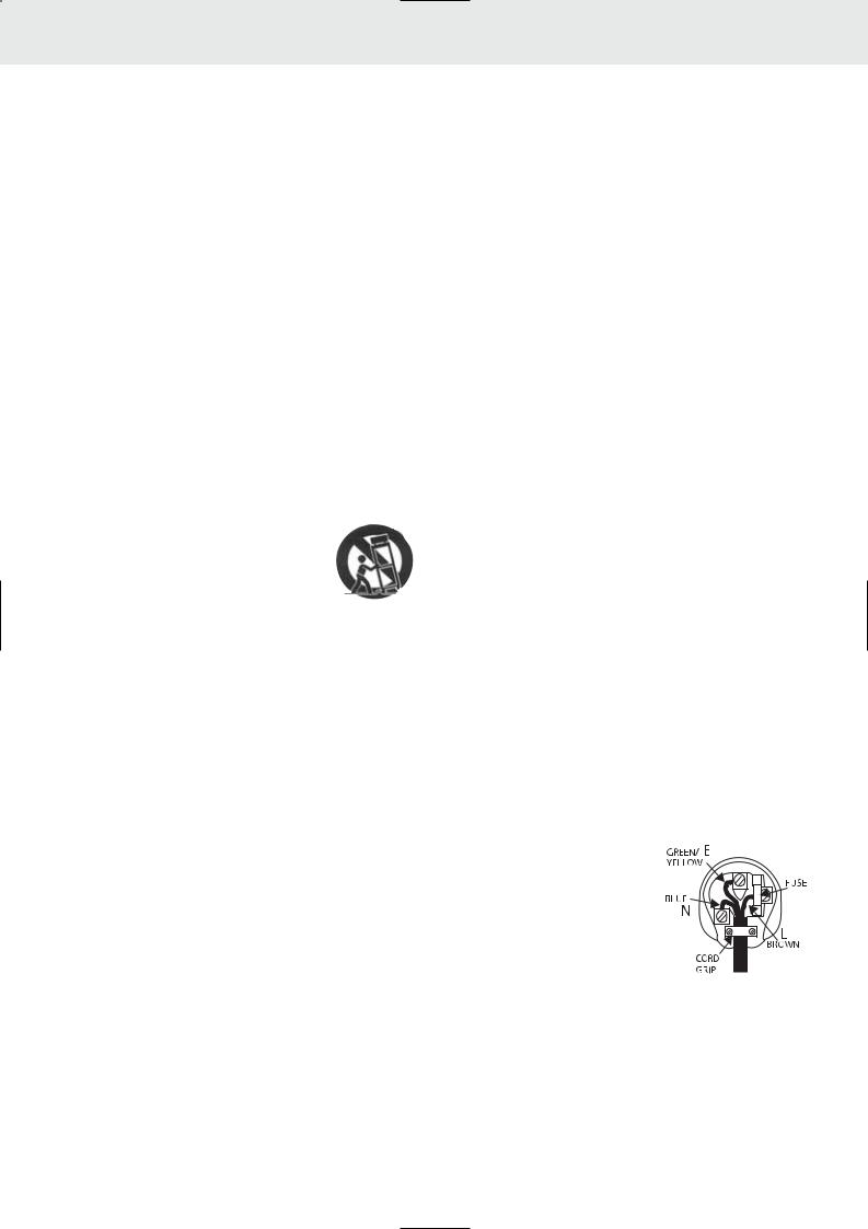
The cord supplied with the 540R is factory fitted with a 13Amp mains plug fitted with a 13Amp fuse inside. If it is necessary to change the fuse, it is important that a 13Amp one is used. If the plug needs to be changed because it is not suitable for your socket, or becomes damaged, it should be cut off and an appropriate plug fitted following the wiring instructions below. The plug must then be disposed of safely, as insertion into a 13Amp socket is likely to cause an electrical hazard. Should it be necessary to fit a 3-pin BS mains plug to the power cord the wires should be fitted as shown in this diagram. The colours of the wires in the mains lead of the 540R may not correspond with the coloured markings identifying the terminals in your plug. Connect them as follows:-
The wire which is coloured BLUE must be connected to the terminal which is marked with the letter 'N' or coloured BLACK.
The wire which is coloured BROWN must be connected to the terminal which is marked with the letter 'L' or coloured RED
The wire which is coloured GREEN/YELLOW must be connected to the terminal which is marked with the letter 'E' or coloured GREEN.
If your model does not have an earth wire, then disregard this instruction.
azur 540R AV receiver 3

REAR PANEL CONNECTIONS
FM / AM antenna
All tuner antenna connections are made here.
Video out
S-Video out - Connect this to your television via an S-Video cable to display the picture of any unit connected via S-Video to the 540R.
Composite Video out - Connect this to your television via an RCA phono cable to display the picture of any unit connected to the 540R via composite video.
S-Video in
Video 1 / Video 2 - These can be used to connect any S-Video source to the 540R.
DVD - Connect to the corresponding S-Video output terminal of a DVD player to play through the 540R. Note that any source can be connected here if desired.
Composite Video in
Video 1 / Video 2 - Connect to the corresponding Composite output terminal of a piece of video source equipment to play through the 540R.
DVD - Connect to the corresponding Composite output terminal of a DVD player to play through the 540R.
It is possible to connect any equipment with a Composite video output to these inputs.
Coax in
CD - Connect to the corresponding Coaxial Digital output terminal of a CD player to play throught the 540R.
DVD - Connect to the corresponding Coaxial Digital output terminal of a DVD player to play throught the 540R.
It is possible to connect any equipment with a coaxial digital output to these inputs.
Optical in
Video 1 / Video 2 - Connect to the corresponding Optical Digital output terminal of a suitably equipped video player to play through the 540R.
DVD - Connect to the corresponding Optical Digital output terminal of a DVD player to play through the 540R.
It is possible to connect any equipment with an Optical Digital output to these inputs.
Coax Out
Connect to an external recording device to record selected digital audio source.
Optical Out
Connect to an external recording device to record selected digital audio source.
Component in
DVD - Connect to the Cr, Cb, Y terminals of a DVD player.
Video - Connect to the Cr, Cb, Y terminals of a games console or other component equipped source.
Component Out
Connect to the Pr, Pb, Y terminals on a Television.
Reset
This is used to reset the whole system including all existing saved information. Insert a paper clip and hold for approx 3 seconds. The unit will be reset and all saved settings will return to factory default settings.
Audio In
CD/Aux - Connect to the line output terminals of a CD player.
Video 1 /Video 2 - Connect to the line output terminals of a video player.
DVD - Connect to the line output terminals of a DVD player.
Tape Play - Connect to the line output terminals on the Tape Deck.
Tape Rec - Connect to the line input terminals on the Tape Deck.
Any line level source can be connected to any of these inputs (except Tape Play/Rec).
6.1 Direct In
Connect to the 7 channel output terminals of a DVD player for playing DVD-A or SACD through the 540R.
6.1 Direct Out
Connect to the 7 channel input terminals of another amplifier, separate power amps or active loudspeakers.
Speaker terminals
Connect to loudspeakers with an impedance of between 4 and 8 ohms.
Power On / off
4 azur 540R AV receiver |
Press this switch to turn on /off this unit. |
540R AV receiver
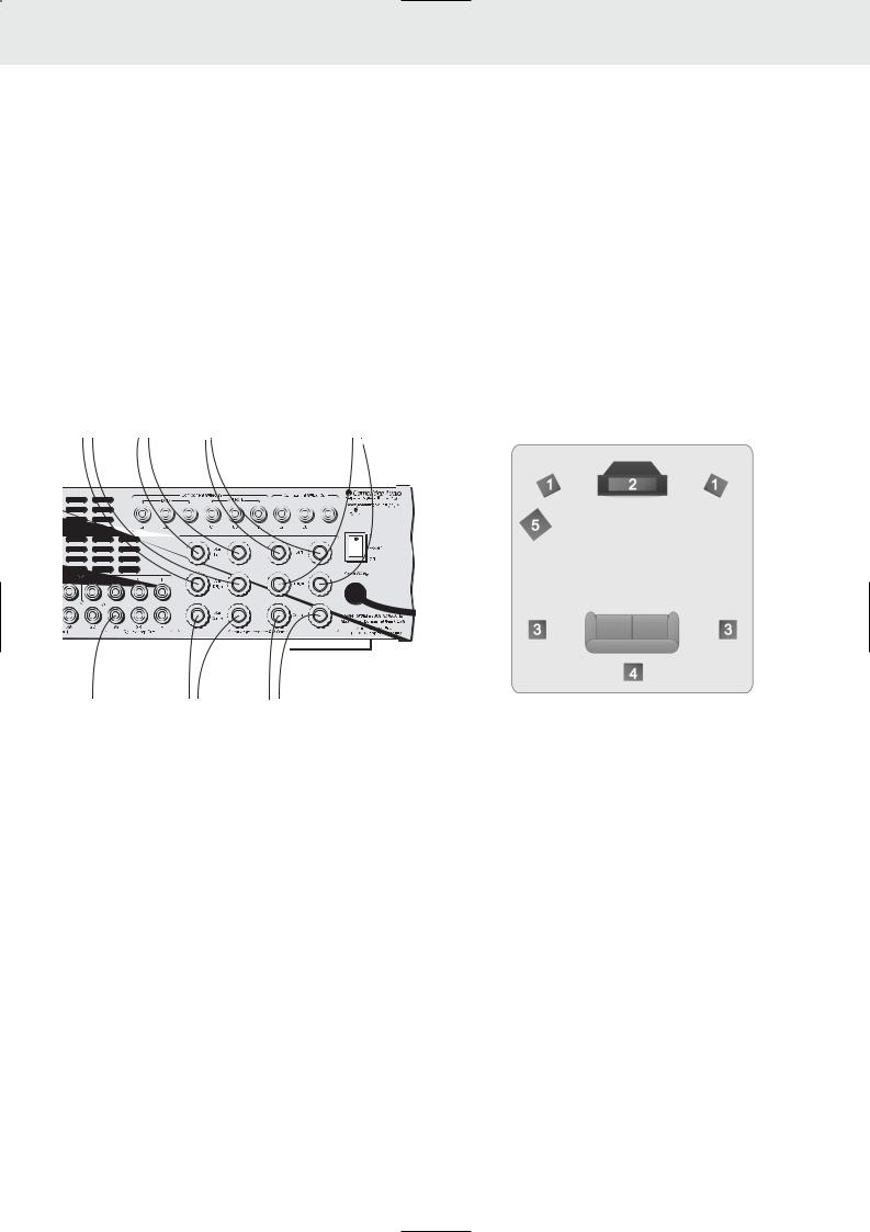
Connecting loudspeakers
To avoid damaging the speakers with a sudden high-level signal, be sure to switch the power off before connecting the speakers.
Check the impedance of your speakers. Connect speakers with an impedance of between 4 and 8 ohms.
The 540R's red speaker terminals are the + (positive) terminals and the black terminals are the - (negative) terminals.
The diagram below shows how loudspeaker connections are made.
Please note that all connections are made via loudspeaker cable except the subwoofer which is connected via a standard RCA phono cable.
To surround |
To surround |
To front left |
To front right |
||||||||
right speaker |
left speaker |
speaker |
speaker |
||||||||
|
|
|
|
|
|
|
|
|
|
|
|
|
|
|
|
|
|
|
|
|
|
|
|
|
|
|
|
|
|
|
|
|
|
|
|
|
|
|
|
|
|
|
|
|
|
|
|
|
|
|
|
|
|
|
|
|
|
|
|
|
|
|
|
|
|
|
|
|
|
|
|
|
|
|
|
|
|
|
|
|
|
|
|
|
|
|
|
|
|
|
|
|
|
|
|
|
|
|
|
|
|
|
|
|
|
|
|
|
|
|
|
|
|
|
|
|
|
|
|
|
|
|
|
|
|
|
|
|
|
|
|
Dipoles diffuse the sound in a slightly different way, and therefore have different positioning requirements: ideally they should be mounted to the side of the listener, and up to 15 degrees above listening height
4.Surround centre speaker - Required for enjoying Dolby® Digital EX (Dolby is a registered trademark of Dolby Laboroatories) or DTS®-ES audio (Under license from Digital Theater, System, In, or DTS (BVI) Limited). Improves the quality of sound effects by filling the gap between the surround left and rear right speakers.
5.Subwoofer - The location of any dedicated subwoofer will greatly effect the quantity and also the quality of the low frequencies. Please see dedicated subwoofer manual for detailed positioning information.
EXPERIMENT !!
REMEMBER - IF IT SOUNDS RIGHT TO YOU, IT IS RIGHT !!
To subwoofer |
To surround |
To front centre |
|
centre speaker |
speaker |
Notes on loudspeaker placement
1.Front left and right loudspeakers - These should be placed equidistant to the left and right of your screen far enough apart to ensure good stereo imaging. If they are too far apart or too close to the corners of the room they will sound distracting and distant. It may be desirable to experiment with the 'toe-in' of the units (angling them towards the listening position) to optimise the front speaker soundstage and imaging.
2.Centre channel Loudspeakers - Ideally your centre channel loudspeaker needs to be positioned directly above or below your screen, facing the listening position.
3.Surround left and right Loudspeakers - If you are using normal hi-fi loudspeakers as your surrounds they should be situated roughly at listening height and facing into the listening position. It is suggested that they are wall mounted or alternatively placed on suitable speaker stands.
Bipolar-type surround speakers can be set up in much the same way as standard 'monopole' types, so try positioning around listening height and angle toward the listener
FM antenna
If you live reasonably close to a transmitter and want to use the provided lead-type FM antenna, connect to the "FM 75 ohm" socket, extend the lead and attach it to a window frame or wall with thumbtacks, or move around the room, where reception is best
In an area where FM signals are weak, it may be necessary to use a 75 ohm unbalanced-type outdoor FM antenna.
AM loop antenna
The high performance AM loop antenna provided with the receiver is sufficient for good reception in most areas.
Connect the loop antenna's wires to the AM antenna terminals.
Place the antenna on a shelf, for example, and move around to obtain the best reception, place as far away as possible from the entire system, speaker leads and the power cords, to prevent unwanted noise.
If the AM loop antenna provided does not receive sufficient reception, it may be necessary to use an outdoor AM antenna.
azur 540R AV receiver 5
 Loading...