

Page 1
Ordering Information
Ordering chart for Flow Switch Controller 8622
Description Type Order Nr.
AC powered Flow switch Controller
3/4" BSP mounting thread 8622-A1M 417965K
3/4" NPT mounting thread 8622-A1N 417966L
DC powered Flow switch Controller
3/4" BSP mounting thread 8622-D1M 417967M
3/4" NPT mounting thread 8622-D1N 417968W
Only connectable to N-Chanel
!
flow switch versions type 8000
Flow/No-Flow Compact
Relay Controller
Type 8622
Owner’s Manual
©1998 Bürkert
All rights reserved.
434305X-Ind**/Jan99
does not provide an ample margin for such inrush currents.
be necessary for your installation if the 10 amp rating
use of a contact protection circuit or a stepper relay may
may be 10 to 20 times their steady-state load rating. The
are reactive and have an inrush current characteristic that
(such as a motor during start-up or incandescent lights)
The relay is rated for a 10 amp resistive load. Many loads
!
Relay Contact Rating:
by the warranty.
housing will not damage it. Such damage is not covered
ensure that compounds that may splash onto the controller
into contact with fluid. Refer to an industry reference to
be mounted in such a way that it does not normally come
the controller is not designed to be immersed. It should
and made of Polypropylene (PP). When installed properly,
The 8622 series of controller housing is liquid-resistant
!
Install In a Dry Location:
your Bürkert representative for further information.
suitability of a controller for your installation, consult
intrinsically safe rating. If you are unsure of the
explosive or flammable liquids, which require an
Compact relay controllers should not be used with
!
Flammable or Explosive Applications:
8622
recommended.
adjustments to powered controllers is not
extreme caution and use only insulated tools. Making
make adjustments during powered operation, use
prior to working on the controller. If it is necessary to
the relay circuit it controls should be turned OFF
serious injury or death. All power to the controller and
contact components that carry high voltage, causing
When the cap of the controller is removed, it is possible to
!
Electrical Shock Hazard:
tests of the installed system, and maintain all components.
appropriate for the application, install it properly, perform
user’s responsibility to select a controller model that is
different mounting and switching configurations. It is the
Bürkert manufactures several models of controller, with
!
User’s Responsibility for Safety:
Compact Relay Controllers from Bürkert
This manual includes information on Flow/No-Flow
INSTALLING OR USING THIS PRODUCT.
PLEASE READ THE ENTIRE MANUAL PRIOR TO
!
About This Manual:
Step One
SAFETY PRECAUTIONS
Page 2
GUIDE T O CONTROLS
FLOWLINE
FLOWLINE
14 VDC 24 VDC
4-20 mA 100 mA
Step Three
Power indicator: This green LED lights when AC power is ON.
Relay indicator: This red LED will light whenever the controller energizes
the relay, in response to the proper condition at the sensor input and after
the time delay.
Power terminals:
AC Version: Connection of 240 VAC power to the controller. The setting
may be changed to 120 VAC if desired. This requires changing internal
jumpers; this is covered in the Installation section of the manual. Polarity
(neutral and hot) does not matter.
DC version: The terminals are located under the circuit card faceplate. For
access to the terminals, remove the single screw which holds the faceplate
to the enclosure. Then, carefully lift the circuit card from the slots in the
enclosure. The two DC power terminals are on the tall, removeable 2-pole
block on the opposite side of the relay from the 3-pole relay block. Insert
the (-) wire into the terminal next to the bottom of the card, and the (+) wire
into the second terminal.
Relay terminals (NC, C, NO):
AC version: The relay terminals are on a 3-pole block.
DC version: The relay terminals are on a tall 3-pole block next to the relay.
Connect the device you wish to control (pump, alarm etc.) to these
terminals: supply to the COM terminal, and the device to the NO or NC
terminal as required. The switched device should be a noninductive load of
not more than 12 amps (AC version), 6 amps (DC version); for reactive
loads the current must be derated or protection circuits used. When the
red LED is ON and the relay is in the energized state, the NO terminal will
be closed and the NC terminal will be open.
Invert switch: This DIP switch reverses the logic of the relay control in
response to the sensor: conditions that used to energize the relay will
make it turn off and vice versa.
Time Delay: After the input changes state, this control sets a delay from
0.15 to 60 seconds before the relay will respond.
Input 1A indicator: This amber LED will indicate a flow or no-flow
condition from the flow switch. With a Normally Closed switch, the LED will
be on for no-flow and off for flow. With a Normally Open switch, the LED
will be on for flow and off for no-flow.
Input terminals: Connect the wiring from the switch to these terminals:
Note the polarity:
AC and DC version: (+) is a 24 VDC, 100 mA power supply (typically
connected to the red wire of a Bürkert switch), and (-) is the ground for the
circuit (typically connected to the black wire of a Bürkert sensor). (S) is the
14 VDC switch terminal (typically connected to the white wire of a Bürkert
sensor). If polarity is reversed between the Red and Black wires, the
status of the FET switch will be reversed.
AC version:
Switch GND
(S) (-) (+)
R
DC version:
Delay
Invert Switch
(S) (+) (-)
SW
+
Com
DC
Power
- +
Relay
NC
Com
NO
-
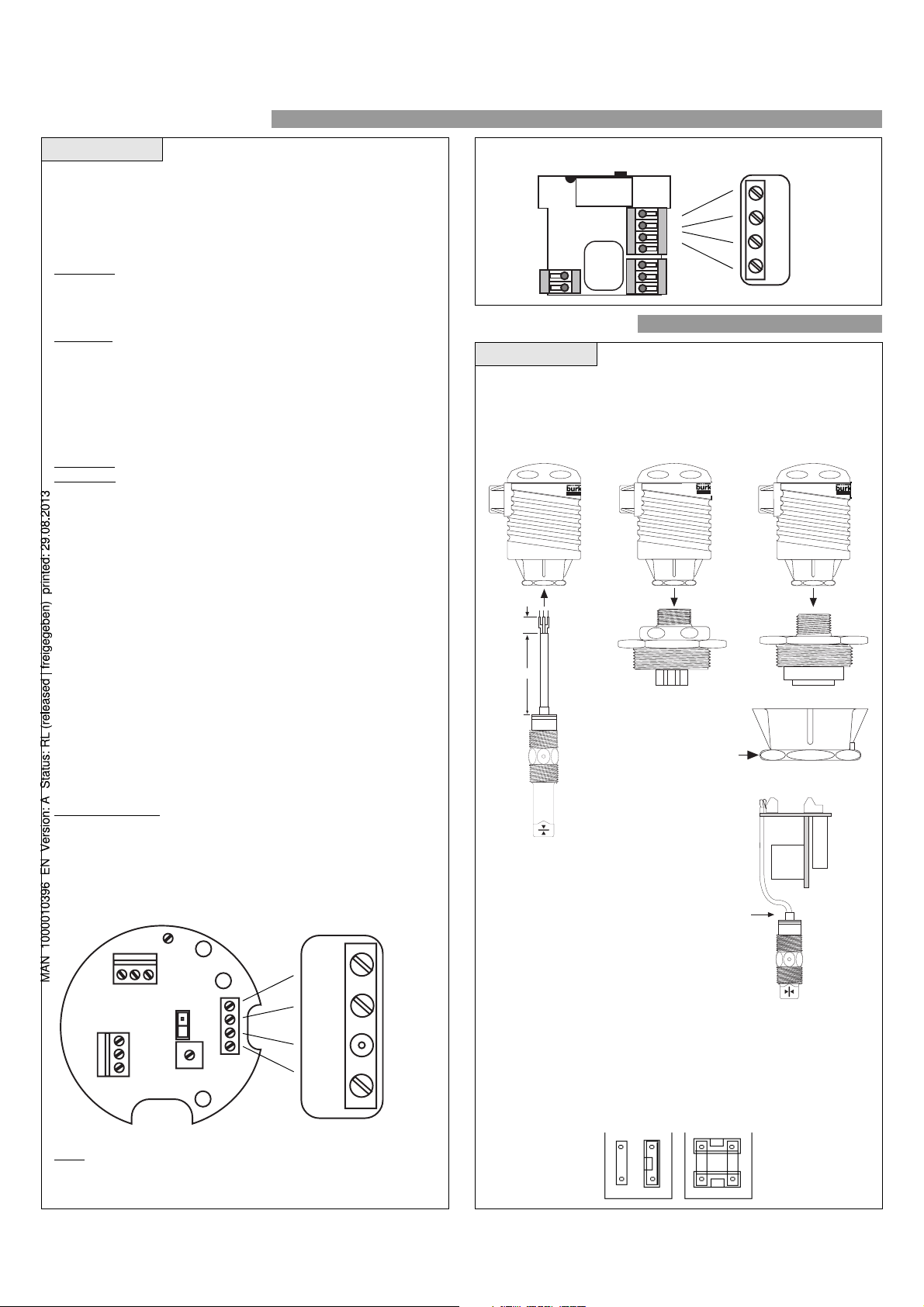
INST ALLA TION
Step Four
3/4" BSP Mounting Thread
Installation of the compact relay controller takes advantage of the 3/4" BSP
thread located on its base. This makes the controller fully compatible with
any of Bürkert's level switches or Smart Trak™ or Switch Pak™ mounting
systems.
FLOWLINE
25.5 mm
1"
76.6 mm
3"
Always tighten the controller
from the wrench flat located on
the swivel base. Never tighten
from the body of the controller.
Switch Cable
When installing a Bürkert level switch, adjust the
cable away from the printed circuit boards in the
controller body. Avoid breaking the seal between
the top of the level switch and the plastic coated
cable.
FLOWLINE
FLOWLINE
Note: The 8622-A1M (417965K) requires that an "N-Channel" Thermo-
Flow switch be used. The 8622-A1M will not work with the "P-Channel"
Flow switch.
GND AC AC
Relay
DELAY
Com NO NC
I ( ON/OFF)
L (ON/OFF)
P
Changing from 240 to 120 VAC
First, remove the printed circuit board from the controller body. Use caution
when removing the PCB. Locate jumpers JWA, JWB and JWC on the end
of the PCB. To change to 120 VAC, remove jumper JWA and place jumpers
across JWB and JWC. To change to 240 VAC, remove jumpers from JWB
and JWC and place a single jumper across JWA.
240 VAC
JWB
JWC
120 VAC
JWB
JWA
JWA
JWC
Page 3

INST ALLA TION TROUBLESHOOTING
Step Five Step Six
Switch Wiring for 8622
White
Black
White
Red
Black
White
Red
Black
Shield
Normally Closed
Red
switches. Amber LED will light for noflow condition and will be off for flow
conditions.
N-Channel switch
Typical wiring for Flow
Shield
Shield
Normally Open
N-Channel switch
condition and will be off for no-flow
conditions.
Amber LED will light for flow
(8622-A..):
AC version
(8622-D..):
DC version
(8622-A..):
AC version
Controller Logic
For all controllers, please use the following guide to understand
the operation of the Bürkert 8622 controller.
1. Make sure the Green power LED is On when power is
supplied to the controller.
2. The input LED is always controlled by the flow switch. When
the flow switch is wired NC, the LED will be OFF during a flow
condition and will be ON during a no-flow condition. When the
flow switch is wired NO, the LED will be ON during a flow
condition and will be OFF during a no-flow condition (see
illustration below).
Version AC (8622-A..)
NC Wiring
ON
input 1A
White
Black*
Red*
* For Version DC (8622-D..) Reverse Red abd Black wires on
input terminals. Led is on facecover.
NO Wiring
OFF
input 1A
NC Wiring
OFF
input 1A
Red*
NO Wiring
ON
input 1A
White
Black*
White
Black
Red
Shield
120/240 VAC Wiring
Polarity does not matter with the AC connections.
HOT
NTRL
GND
NO C NC
NO Wiring
NO C NC
GND AC AC
HOT
NTRL
GND
GND AC AC
NC Wiring
(8622-D..):
DC version
HOT
NTRL
GND
GND AC ACNO C NC
HOT
NTRL
GND
GND AC ACNO C NC
White
Black*
Red*
White
Black*
Red*
3. The relay LED ON indicates when the relay is energized. The
relay LED OFF indicates the relay is de-energized. With the
invert switch OFF, the relay is de-energized when the input
LED is OFF and the relay is energized when the input LED is
ON. With the invert switch in the ON position, the relay is
energized when the input LED is OFF and the relay is deenergized when the input LED is ON.
Note: The normal state of the relay is de-energized. When the
relay becomes energized, the normally closed side of the
relay becomes open and the normally open side of the relay
becomes closed (see illustration below).
Invert Off
De-energized
R
Invert On
Energized
R
NC
C
NO
NC
C
NO
Invert Off
Energized
R
Invert On
De-energized
R
NC
C
NO
NC
C
NO
Page 4

SPECIFICA TIONS
FLOWLINE
FLOWLINE
Step Two
Supply voltage: 14-36 VDC (type 8622-D..)
120 / 240 VAC, 50 - 60 Hz. (type 8622-A..)
Consumption: .25 amps
Sensor supply: 13.5 VDC @ 100 mA
Relay type: Isolated single pole double throw (SPDT)
relay, Form C
Relay load: Switching voltage
240 VAC/150VDC max. (8622-D..)
380 VAC/150VDC max. (8622-A..)
Switching current
6 Amps (non inductive load) (8622-D..)
12 Amps (non inductive load) (8622-A..
Relay mode: Selectable, NO or NC
Time delay: 0 to 60 seconds
LED indication: Sensor, relay & power status
Fail safety: Power fail-safe
Enclosure rating: NEMA 4X / IP65
Enclosure material: Polypropylene (U.L. 94 VO)
Enclosure rotation: 300° swivel base
Temperature range:F: -40° to 158°
C: -40° to 70°
Conduit connection:1/2" NPT
Dimensions
17.8
mm
71.5
mm
)
Faceplate Cover
(8622-A..):
AC version
STATUS
Delay INVERT
- +
SENSOR
RELAY
Top wiew
AC version:
Delay
120 VAC, 50-60 Hz, 0.25 Amp.
240 VAC, 50-60 Hz, 0.25 Amp.
Always replace this safety cover after service
Model: 8622-A..
S/N: XXXXXX
Power supply
120/240 VAC,50-60 Hz,
0.25 Amps
DELAY
Maximum relay Rating
250 VAc, 12 A, 1/2 Hp
(8622-D..):
DC version
POWER
Relay LED
I (ON/OFF)
L (ON/OFF)
DELAY
(red)
R
P
Power LED
Input A LED
(green)
Invert
Relay
Terminal
Invert
AC Input
GND AC AC
Relay
Com NO NC
(amber)
Input
Terminal
Delay
DC
- +
Delay
Invert Switch
Relay
Relay
Terminal
Sensor
Input 1
Power
Supply
Input
Terminals
NC
Com
NO
Relay
Latch/ Invert Logic
Time Delay
AC version
NC
C
NO
(+)
(-)
S
DC
DC
Side wiew
DC version:
Sensor
Input 1
DC version
Power
Supply
Relay
Latch/ Invert Logic
Time Delay
120
mm
71.5
mm
mm
17.8
mm
95
56.7
mm
25.5
mm
Make a Fail-Safe System:
mm
81.7
FLOWLINE
mm
25.5
FLOWLINE
Power Input
NC
C
NO
(+)
(-)
S
AC
AC
GND
Design a fail-safe system that accommodates the possibility of relay or power failure. If power is cut off to the controller, it will de-energize the relay. Make sure
that the de-energized state of the relay is the
safe state in your process. For example, if controller power is lost, a pump filling a tank will turn off if it is connected
to the Normally Open side of the relay.
While the internal relay is reliable, over the course of time relay failure is possible in two modes: under a heavy load the contacts may be “welded” or stuck into
the energized position, or corrosion may build up on a contact so that it will not complete the circuit when it should. In critical applications, redundant backup
systems and alarms must be used in addition to the primary system. Such backup systems should use different sensor technologies where possible.
While this manual offers some examples and suggestions to help explain the operation of Bürkert products, such examples are for information only and are not
intended as a complete guide to installing any specific system.
 Loading...