

Page 1
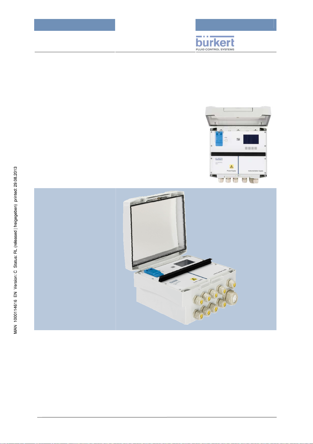
mxCONTROL Type 8620
Type 8620
mxCONTROL
Multifunction
Water Treatment
Controller
Operating Instructions
Page 1
Page 2

mxCONTROL Type 8620
We reserve the right to make changes without notice!
© 2009 - 2010 Bürkert Werke GmbH & Co. KG
Operating instructions 1007/03_EU_EN_00805853
Page 2
Page 3

mxCONTROL Type 8620
Contents
CONTENTS 3
1 THE OPERATING INSTRUCTIONS 6
2 INTENDED USE 7
2.1 Restrictions 7
2.2 Anticipated misuse 7
3 GENERAL SAFETY INSTRUCTIONS 8
4 GENERAL INFORMATION 10
4.1 Scope of Delivery 10
4.2 Warranty Regulations 10
4.3 Certifications 10
4.4 Information in the Internet 10
5 ABBREVIATIONS 11
5.1 Abbreviations in Software and Documentation 11
5.2 Display of the units 15
6 TECHNICAL DATA 17
6.1 Technical Specifications 17
6.2 Type Plate – Example 20
6.3 Hardware Structure 21
6.4 Module Overview 22
7 INSTALLATION 23
7.1 Safety Notes 23
7.2 Quick Start Guide 23
7.3 Mechanical Installation 24
7.4 Electrical Connections 24
7.5 Terminal Strip Pin Assignment 26
7.5.1 Power Supply (PS) 26
7.5.2 Instrumentation Supply (IS) 27
7.6 Download of a Configuration and Parameter File 27
8 DESCRIPTION OF HUMAN-MACHINE INTERFACE 28
8.1 Safety Notes 28
8.2 Operating and Display Elements 28
8.3 Operation Mode 29
8.3.1 Automatic & Manual Mode Key 29
8.3.2 Automatic Mode (LED on) 29
8.3.3 Manual Mode (LED off) 29
8.4 Layout of Menu Screens 30
9 MENU STRUCTURE 31
9.1 Principle of Menu Tree Structure 31
9.2 Setting Numeric Values 33
10 PASSWORD PROTECTION 34
11 GENERAL SOFTWARE CONCEPT AND FUNCTIONS 36
11.1 Functional Overview 36
11.2 Up- and Downloading of Configuration/Parameter Files 37
11.2.1 Download 37
11.2.2 Upload 38
11.3 Data Logging 39
11.3.1 Selection of SD card size for Data Logging purposes 42
11.3.2 Start of Data Logging (enabling) 43
11.3.3 Stop of Data Logging (disabling) 44
Page 3
Page 4

mxCONTROL Type 8620
11.4 Configuration and Parameterization 45
11.4.1 Preface about Configuration/Parameterisation 45
11.4.2 Operating Language 45
11.4.3 Factory Setting of Parameters and Factory Reset 45
11.5 Communication 46
11.5.1 USB 46
11.5.2 Ethernet (only devices with Ethernet option) 46
11.5.3 (Remote) Device access via PC-Tool 52
12 INPUTS 55
12.1 Digital Inputs 55
12.1.1 Binary Inputs 56
12.1.2 Frequency Inputs 57
12.1.3 Pulse Counter Inputs 62
12.2 Analog Inputs 62
12.2.1 4…20 mA Inputs 62
12.2.2 Pt100 Inputs 69
13 OUTPUTS 72
13.1 Relay Outputs 72
13.1.1 Relay as Binary Output (On/Off) 73
13.1.2 Relay as PFM Output 73
13.1.3 Relay as PWM Output 74
13.1.4 Configuration (CodeLevel: Specialist) 74
13.2 Analog 4...20 mA Outputs (Option) 75
13.3 Transistor Outputs (Option) 77
13.3.1 Transistor output as On/Off-Output 77
13.3.2 Transistor output as PFM Output 77
13.3.3 Transistor output as PWM Output 77
13.3.4 Transistor output as fast PWM Output 78
13.3.5 Configuration (Code Level: Specialist) 79
14 CONTROLLER MODULES 80
14.1 Common Settings 80
14.1.1 Automatic and Manual Mode 80
14.1.2 Definitions for “Inversion” and “All Timers” 80
14.1.3 System Switch override function (Specialist level) 81
14.1.4 Flow Switch override function (Specialist level) 82
14.1.5 Maximum Output Timer (MOT) 84
14.2 General PID controller (COMMON_PID) 85
14.3 Conductivity Control Modules 94
14.3.1 On-/Off-Control (COND_CONTROL) 95
14.3.2 PI-Control (COND_PI) 99
14.3.3 On-/Off-Ratio Control (COND_CONTROL_RATIO) 103
14.3.4 PI-Ratio Control (COND_PI_RATIO) 106
14.4 Corrosion Display (CORROSION-DISPLAY) 109
14.5 pH Controller Modules (PH_ACID_CAUS) and (PH_ACID_OR_CAUS) 110
14.5.1 pH-Control (PH_ACID_CAUS) 110
14.5.2 pH Control (PH_ ACID_OR_CAUS) 115
14.6 Dosing of oxygen absorption media 119
14.6.1 Flow and temperature-based dosing (O2_SCAV_CTRL_RATIO) 119
14.6.2 Process-value-proportional dosing (OPEN_PROP) 123
14.7 Chlorine / Redox Control (CL_ORP) 125
14.8 Batch Dosing (BATCH) 128
14.9 Time scheduled Biocide Dosing (BIOCIDE_DOSING) 131
14.10 Monitoring Process Values (MONITOR_PV) 137
14.11 Dual Channel Totalizer (TOTALIZER) 139
Page 4
Page 5

mxCONTROL Type 8620
15 ALARM AND ERROR MESSAGES 142
15.1 Alarm function 142
15.2 Displaying (Input-) Alarms and different (Output-) States 144
15.3 Error Messages and Warnings 145
16 MAINTENANCE AND TROUBLESHO OTING 153
16.1 Safety Notes 153
16.2 Maintenance work 153
16.3 Malfunctions 153
17 SPARE PARTS 154
18 PACKING AND TRANSPORT 154
19 STORAGE 154
20 DISPOSAL 154
21 APPENDICES 155
21.1 Project (for example "BW 06") 155
21.1.1 Input/Output Assignment – project "BW 06" 155
21.1.2 Wiring Diagram Example for Project "BW 06" 155
21.2 Power Supply of Actuators/Sensors 156
21.2.1 Power Supply out of the mxCONTROL 156
21.2.2 Separate Power Supply 156
21.3 Hardware Version 1 157
21.3.1 PIN Assignment for Power Supply Level (Power Supply) 157
21.3.2 PIN Assignment for Low Voltage Level (Instrumentation Supply) 158
21.3.3 Connection Examples for Inputs and Outputs 159
21.4 Hardware version 2 162
21.4.1 PIN assignment for power supply level (power supply) 162
21.4.2 PIN Assignment for Low Voltage Level (Instrumentation Supply) 163
21.4.3 Connection Examples for Inputs and Outputs 164
21.5 Main Menu Structure – Menu Tree (Example for Project "BW 06T") 168
21.5.1 Processdata – Inputs – Outputs 168
21.5.2 Processdata – Cond Control 169
21.5.3 Configuration of Inputs 170
21.5.4 Configuration of the Codes 171
21.5.5 System Settings 172
21.5.6 Up-/Download - Download 173
21.5.7 Up-/Download – Upload 174
21.5.8 Data Logging / Calibration / Clock 175
21.6 Data Logging File – Example 176
Page 5
Page 6

mxCONTROL Type 8620
1 The operating instructions
WARNING!
The operating instructions must be read and understood.
Read the operating instructions carefully.
Note the chapters Intended Use and General Safety Instructions!
Presentation elements
DANGER!
Mains voltage! Immediate danger!
Death or serious injuries are the result of non-compliance with the safety instructions.
DANGER!
Immediate danger!
Death or serious injuries are the result of non-compliance with the safety instructions.
WARNING!
Potentially dangerous situation!
Serious injuries or death may result from non-compliance with the safety instructions.
CAUTION!
Potentially dangerous situation!
Medium or light injuries may result from non-compliance with the safety instructions.
CAUTION!
Potentially dangerous situation!
Likely property damages in case of non-compliance.
Designates important additional information, tips and recommendations important for your
safety and the flawless function of the device.
Refers to information in these operating instructions or other documentation.
→ Marks a section you have to carry out.
Page 6
Page 7

mxCONTROL Type 8620
2 Intended Use
WARNING!
Hazards to persons, equipment in the vicinity and the environment may result when not using
the „Type 8620 mxCONTROL“ as intended.
The „Type 8620 mxCONTROL“ may not be used in explosion-hazard rooms.
The „Type 8620 mxCONTROL“ may only be used at temperatures from 0 °C.
The permissible data and operating conditions specified in the operating instructions as well
as the application areas described in chapter 6.1 must be followed. The customer is responsible for choosing the device suitable for his application.
Proper transport, proper storage and installation as well as careful operation and service are
the prerequisites for safe and flawless operation.
Use the „Type 8620 mxCONTROL“ only as intended.
The „Type 8620 mxCONTROL“ is a multifunction controller. This multifunction controller was
developed to automate the control and process variables in a water treatment system (e.g.
boiler, cooling tower or Reverse Osmosis system).
Sophisticated electronics and state of the art control algorithms ensure that optimum process control is
maintained at all times, with minimal operator intervention.
Depending on the hardware version, the „Type 8620 mxCONTROL“ is capable of processing several
analog and digital inputs as well as several relay, transistor and analog outputs at the same time.
Combined with an easy to read display in three languages: English, German and French (other
languages on request), the device offers nearly unlimited options for process automation systems.
The „Type 8620 mxCONTROL“ functions are highly software-based. All configuration and
parameter files can be created in a quick and unsophisticated manner with the help of a PC Tool
and downloaded in the „Type 8620 mxCONTROL“ via SD card or USB. Alternatively, the optional
Ethernet interface can be used to configure and parameterize the device. The operator can then enter
and display all important variables and parameters using five soft-touch keys.
The „Type 8620 mxCONTROL“ is supplied with an SD card containing not only the configuration and
parameter files but also the operating instructions.
Three authorization levels (code level) allow for the safe operation of the „Type 8620 mxCONTROL“:
Open access, access only for instructed operators, access for specialists.
2.1 Restrictions
Note possibly existing restrictions when exporting the device.
2.2 Anticipated misuse
• The „Type 8620 mxCONTROL“ may not be used in explosion-hazard areas!
• Do not put mechanical stress on the unit (e.g. by storing heavy objects on it or using it as a
step).
Page 7
Page 8

mxCONTROL Type 8620
3 General Safety Instructions
These safety instructions do not take any
• Incidents and occurrences into account which may occur during assembly, operation and
maintenance of the devices.
• Local safety regulations where the operating party is responsible for its compliance, also in
Danger from electrical voltage
Reaching into the system presents an acute risk of injury.
Always switch off the power before beginning with the work activities and secure it against being
switched back on inadvertently! Obey the applicable accident prevention and safety regulations for
electrical devices!
Inadvertent operation or impermissible restrictions may cause general danger situations
through the downstream actuators, including physical injuries.
regard to the installation staff.
DANGER!
WARNING!
Take proper precautions to prevent accidental actuation or inadmissible impeding.
Dangerous situations may develop during installation and repair activities. This type of work may only
be carried out by authorized technical personnel and with suitable tools!
After an interruption of the electric supply, ensure a defined and controlled restart of the processes!
WARNING!
Personal injuries and damage to the system may occur following a system interruption or after
manual operation through unwanted operation of output devices.
Before changing the mode of operation (Manual or Automatic), appropriate measures must be
taken to prevent harm to personnel and the system due to unwanted actuation of an output device
(e.g. biocide pump).
CAUTION!
The general engineering rules apply to the deployment planning and operation of the device!
Disregarding these rules may result in injuries and/or damages to the device and possibly its
environment.
Follow the general rules of engineering!
CAUTION!
Electrostatically endangered components/modules
The device contains electronic components which may react sensitively against electrostatic
discharges (ESD). Touching electrostatically charged persons or objects puts these components at
risk. In the worst case, they will be destroyed or fail after startup.
Follow the requirements according to DIN EN 61340-5 to minimize or prevent the possibility of
damage due to sudden electrostatic discharge!
Make also sure not to touch the electronic components if supply voltage is supplied!
Page 8
Page 9

mxCONTROL Type 8620
CAUTION!
Hardware and Software modifications and changes
For safety reasons unauthorised modifications and changes of hardware and software are not allowed.
Make sure to comply with the notes, thresholds, operating modes and safety instructions given in this
manual.
Non-compliance with this manual and operating sequence will void any liability claims.
CAUTION!
Temporary protection against overload and short circuit
Instrumentation Supply part (24 V DC): the device is protected against destruction by overload and
short circuit. No safe function is ensured for the duration of such disturbance. After such a disturbance,
the „Type 8620 mxCONTROL“ automatically continues its normal operation.
The plant must be dimensioned so that the sum of extracted current of all actuators/sen¬sors
connected at the Instrumentation Supply side never exceeds the value of 1.04 A.
The „Type 8620 mxCONTROL“ was developed on the basis of recognized technical safety
rules and corresponds to the state of technology. Hazards may nonetheless develop.
Operate the „Type 8620 mxCONTROL“ only in flawless condition and in compliance with the
operating instructions. Also make sure to comply with the conditions of use according to
the specifications in chapter 6.1 „Technical Specifications“ and on the type plate of the
device.
Non-compliance with these instructions and unauthorized tampering with „Type 8620
mxCONTROL“ voids any liability by us; the warranty for the device and accessories also
becomes void!
Page 9
Page 10
mxCONTROL Type 8620
4 General Information
4.1 Scope of Delivery
Verify immediately after receiving the shipment that the contents are not damaged and agrees with the
specified scope of delivery as stated on the enclosed "Delivery instructions"; also make sure that the
details on the type plate match the conditions of use.
Please contact our sales centre immediately in case of disagreements:
Bürkert Fluid Control Systems
Sales Center
Christian-Bürkert-Str. 13-17
D-74653 Ingelfingen
Germany
or your Bürkert distribution centre.
Phone: +49 (0)7940 - 10 111
Fax: +49 (0)7940 - 10 448
Email: info@de.buerkert.com
4.2 Warranty Regulations
This document contains no promise of guarantee. Please refer to our terms of sales and delivery. The
warranty is only valid if the device is used as authorized in accordance with the specified application
conditions.
The warranty extends only to defects of the „Type 8620 mxCONTROL“ and its components.
We accept no liability for any kind of collateral damage which can occur due to failure or
malfunction of the device.
4.3 Certifications
The certification designation on the Bürkert type plates refers to the Bürkert products.
More information on the certifications can be found in the chapter
6.1 “Technical Specifications“.
4.4 Information in the Internet
You can find operating instructions and data sheets on type 8620 in the Internet at:
www.buerkert.de → Technical Data → Operating instructions → Data sheets → Type 8620.
The complete documentation is supplied on the SD card.
Page 10
Page 11
mxCONTROL Type 8620
5 Abbreviations
5.1 Abbreviations in Software and Documentation
Further abbreviations (Error messages) can be found in chapter 15.3.
Abbreviation Explanation
+Tm Maximum output time
+TmPB Maximum pre-bleed duration
AH Higher Alarm Process Value
AL Lower Alarm Process Value
Alarm- Lower alarm limit
Alarm+ Upper alarm limit
AlarmHys Alarm hysteresis in % of process value range
Alarm H Upper Process Value Alarm
Alarm L Lower Process Value Alarm
AnalogIn 1 to 4 Analog input 1 … 4
ASL Acid (pump) stop limit (Acid Stop Limit)
ASL PumpStop Pump Stop due to the ASL alarm
Au Automatic Mode
BATCH (or Batch Dosing) Batch Module (dosing by batches)
Binary Binary input (digital: 0 / 24 VDC)
BIOCIDE_DOSING Biocide dosing module
BioDos Biocide dosing module (abbrev.)
Cd Conductivity module (On/Off control) - abbrev.
Cd-PI
Cd-PIr
Cd r
CL Chlorine
CL/ORP Chlorine/Oxidising Redox Potential PI-Control Module - abbrev.
CL_ORP Chlorine/Oxidising Redox Potential-PI-Control Module
CM Calibration mode: 4-20mA input or output is currently calibrated
CMD Module output (command) to actuator (%) - proportional/integral
CMD A Module output (Acid) - acid pump
CMD C Module output (Caustic) - caustic pump
CMD on Output value at module output e.g. during dosing
CMDsafe
CMD 1, CMD 2 Module output for channel 1, module output for channel 2 (at BIOCIDE_DOSING)
Cond Conductivity
COND_CONTROL Conductivity module (On/Off control)
COND_CONTROL_RATIO
COND_PI
COND_PI_RATIO
Cor Corrosion
CorroD Corrosion Display Module (short name)
Conductivity module (PI control) - abbrev.
(in part with 3-point step output)
Conductivity module (PI-Ratio-Control) - abbrev., set point depending on MakeUp-Channel ratio
Conductivity module (On/Off Ratio-Control) - abbrev., set point depending on
Make-Up-Channel ratio
Safety output value, it is active if
- on the 4…20 mA input less than 3.5 mA or more than 20.5 mA are applied,
- on the Pt100 input, a temperature outside of the measuring range is applied
Conductivity module (On/Off Ratio-Control), set point depending on Make-UpChannel ratio
Conductivity module (PI control)
(in part with 3-point step output)
Conductivity module (PI-Ratio-Control), set point depending on Make-Up-Channel
ratio
Page 11
Page 12

Abbreviation Explanation
CORROSION_DISPLAY Corrosion Display Module
Cut- Lower CutOff threshold (Module "COMMON_PID")
Cut+ Upper CutOff threshold (Module "COMMON_PID")
D- Max. negative set point change per minute, falling (Delta-)
D+ Max. positive set point change per minute, rising (Delta+)
Dbnd Deadband - to prevent vibration of the actuator
DigIn 1 … 4 Digital input 1 … 4
Dos1 … Dos8 Biocide timer settings (8 per day per channel)
FA AD-Fault
Fc Calibration Data Fault
FC Configuration Fault
fF Flow switch: “No Flow”
FI Input Fault
Filter Filter stage (for Low Pass Filter)
Fmax Maximum actuator output pulse rate per minute or per hour
fo forced by other modules
Freq- Lower frequency value of a frequency range
Freq+ Upper frequency value of a frequency range
Fr Friday
fS System switch: “Stand-by”
FS Sensor Fault; Full scale (in connection with Technical Specification)
FSOR Flow switch override
Hyst Switching hysteresis set in engineering units
HO Process Value state, Value Hold during User Calibration of 4-20mA inputs
Inv Inversion of the sense of action of a module/signal
IS Instrumentation Supply
Kp Gain/amplification factor (in [% control output/PV unit])
Kx Ratio factor for internal set point calculation
Lim- Lower output limit in %
Lim+ Upper output limit in %
Ma Manual (operation) mode
Mo Monday
MONITOR_PV Module - monitoring only a Process Value PV (data logging)
Mon PV Module - monitoring only a Process Value (data logging) - short name
MOT Maximum Output Timer
MPY Mils Per Year
MTPB Maximum pre-bleed timer
µMPY Micro Mils Per Year
nA Input not active
O2_SCAV_CTRL_RATIO Dosing of O2-absorption media based on flow and temperature
O2SCR Dosing of O2-absorption media based on flow and temperature - abbrev.
OF Output fault of the 4…20 mA outputs
OPEN_PROP Dosing proportionally to process value
OpProp Dosing proportionally to process value - abbrev.
ORP Oxidising Redox Potential (Redox)
PB
PB ratio
PFM Pulse Frequency Modulation
pH-AC
pH-A/C
Page 12
Pre-Bleed Limit of biocide dosing module in connection with the
COND_CONTROL and COND_PI modules
Pre-Bleed Ratio Limit of biocide dosing module - only in connection with the
modules COND_CONTROL_RATIO and COND_PI_RATIO
pH PI Module with selection of acid and caustic pump (abbrev.)
pH PI Module with selection of acid or caustic pump (abbrev.)
mxCONTROL Type 8620
Page 13

mxCONTROL Type 8620
Abbreviation Explanation
PH_ACID_CAUS
PH_ACID_OR_CAUS
pH PI Module with selection of acid and caustic pump
pH PI Module with selection of acid or caustic pump
ptf.binary Binary input (digital, potential-free)
PS Power Supply
Psd Process switching difference
PumpStop Pump stopped because corrosion limit exceeded
PV Process value
PV BSi Process value of Batch size
PV cal Conductivity value (for TDS-calibration)
PWM Pulse Width Modulation
r read (access via configuration menu or via XML-configuration or parameter file)
Ref.Date Week1 Reference Date for week 1
rw read and write (access via configuration menu or via XML-config. / parameter file)
Sa Saturday
Scal- Minimum value of sensor range (in engineering units)
Scal+ Maximum value of sensor range (in engineering units)
SP Set point
SP BSi Set point of Batch size
SpecFunc Special input function for 4…20 mA inputs
SPLim Set point minimum (internal calculation for conductivity)
SPLim- Lower set point limit for pH measurement
SPLim+ Upper set point limit for pH measurement
SP Limit Set point Limiter
SP Ramp Set point ramp
SSOR System switch override
State Current state of dosing process in batch module
Su Sunday
Tco cl Time for complete closing: 100% Æ 0%)
Tco op Time for complete opening: 0% Æ 100%)
Tdose (Total) Biocide dosing time; Batch dosing time
TDS Total Dissolved Solids
TDS cal TDS-value (Total Dissolved Solids value)
Th Thursday
+Tm Maximum output time
+TmPB Maximum pre-bleed duration
Tm1 Interval between main biocide dosing & post dosing
Tm2 Delay after post-dosing before conductivity control resumes
Tn Reset time in seconds
Tperiod period duration
Tpuls Pulse duration of the actuator output in milliseconds or seconds
Tsample Sample time of the respective control loop; sample time with data logging
Tu Tuesday
Tv Rate time
w write (access via configuration menu or via XML-configuration or parameter file)
Warn- Lower warning limit
Warn+ Upper warning limit
WarnHys Warning hysteresis in % of process value range (AwHyst)
WH Upper warning process value
We Wednesday
WL Lower warning process value
YA Abbreviation in the alarm display for ASL-pump-stop
Page 13
Page 14

Abbreviation Explanation
YF Out fails (MOT is expired)
YS Safety output value is active (due to input/sensor fault)
mxCONTROL Type 8620
Page 14
Page 15

mxCONTROL Type 8620
5.2 Display of the units
Because of the limited display, there is not always sufficient room available for the detailed display of
the unit. Depending on the available positions, 3 or 6 positions are shown in the display; the
equivalents as well as the output during data logging are listed in the following table, arranged by
groups.
Display
max. 3 characters
Volume units
L L L Litre
hL hL hL Hectolitre
m3 m3 m3 Cubic metre
Gal Gal US Gal US U.S. liq. Gallon
bbl bbl US bbl US U.S. Barrel
gal gal Im gal Imp Imperial Gallon
ft3 ft3 ft3 Cubic Foot
yd3 yd3 yd3 Cubic Yard
Flow units
L/s L/s L/s Litre per second
L/m L/min L/min Litres per minute
L/h L/h L/h Litre per hour
m3M m3/min m3/min Cubic metre per minute
m3H m3/h m3/h Cubic metres per hour
G/s Gal/s Gal/s US U.S. liq. Gallons per second
G/m Gal/m Gal/m US U.S. liq. Gallons per minute
G/h Gal/h Gal/h US U.S. liq. Gallons per hour
g/s gal/s gal/s Imp Imperial gallons per second
g/m gal/m gal/m Imp Imperial gallons per minute
g/h gal/h gal/h Imp Imperial gallons per hour
bbS bbl/s bbl/s US U.S. Barrel per second
bbM bbl/m bbl/m US U.S. Barrel per minute
bbH bbl/h bbl/h US U.S. Barrel per hour
f3S ft3/s ft3/s Cubic Feet per second
f3M ft3 /m ft3 /min Cubic Feet per minute
f3H ft3/h ft3/h Cubic Feet per hour
P/s Pul/s Pul/s Pulses per second
P/m Pul/m Pul/m Pulses per minute
Units for chemical analysis
µS µS/cm µS/cm Microsiemens per centimetre
mS mS/cm mS/cm Millisiemens per centimetre
MPY MPY MPY Mils per year
µMY µMPY µMPY Micromils per year
mV mV mV Millivolt
mgL mg/L mg/L Milligrams per litre
%Sa %Sat %Sat Percent of saturation
pH pH pH pH
Temperature units
°C °C °C Degree Centigrade
°F °F °F Degree Fahrenheit
°Ra °Rank °Rank Degree Rankine
K K K Kelvin
Display
max. 6
characters
Display of the unit
selection as well as
data logging
Page 15
unit
Page 16

Display
max. 3 characters
Display
max. 6
characters
Display of the unit
selection as well as
data logging
mxCONTROL Type 8620
unit
Pressure units
bar bar bar Bar
mba mbar mbar Millibar
psi psi psi psi
Various units
ppm ppm ppm Parts per million
V V V Volt
mA mA mA Milliamps
Pul Pulse Pulse Pulse
Hz Hz Hz Hertz
% % % Percent
Other parameter units
ms ms ms Milliseconds
s s s Seconds
min min min Minutes
h h h Hours
/m /min /min Per minute
/h /h /h Per hour
Page 16
Page 17

mxCONTROL Type 8620
6 Technical Data
6.1 Technical Specifications
These operating instructions are valid from Firmware revision: C.00.00.00
General Details of the Device
Enclosure with sealed keypad and display
Enclosure outer dimensions L x W x H 230 x 204 x 119 mm (without cable glands)
Enclosure material PC (UL94) with transparent door and key
Weight 1.8 kg
Degree of protection
Graphic display, large and backlighted 128 x 64 dots, two colored (blue and white)
Keypads for manual operation 5 keys for user inputs
Operating temperature 0 … +50 °C
Storage temperature -20 … +60 °C
Electrical Details
Mains voltage (power supply) 100 … 240 V AC, 50/60 Hz, no adjustment necessary
Power consumption (of mxCONTROL device) max. 35 W (incl. sensor supply at Instrumentation Supply part)
Total power consumption
(using the internal power distribution)
Total input current I
Total output current I
(using internal power distr.) max. 10 A
in
out
(using the internal power distribution)
Instrumentation supply for sensors / transistor
outputs
Fuse for device protection
(Instrumentation)
Fuse for Relays outputs
Inrush current (typ.) Cold start: 30 A / 230 V AC
Electrical Connections
Electrical connection Power Supply Hardware version 1: Screw terminals, grid 5.08 mm,
Electrical connection Instrumentation Supply Hardware version 1: Screw terminals, grid 3.81 mm,
Cable glands and cables
IP 65 and NEMA/UL 50, Type No. 4X, with door closed and
properly sealed cable glands,
additional cover of USB port and SD card slot
max. 2400 W (at 240 V AC) or max. 1100 W (at 110 V AC)
incl. connected actuators at Power Supply part
<10 A (incl. device power consumption of 35 W)
24 V DC (±5 %), max. 1.04 A (25 W),
short circuit and overload protected
internal: electronic fuse, recovers automatically after fault
condition is removed
Relay outputs to be fused in external installation according to
actuators
for wire gauges 0.14 … 1.5/2.5 mm
Hardware version 2: Spring type terminal, grid 5.0 mm,
for wire gauges 0.2 … 2.5/4.0 mm
for wire gauges 0.14 … 1.0/1.5 mm
Hardware version 2: Spring type terminal, grid 3.5 mm,
for wire gauges 0.2 … 1.5 mm
2
(AWG 26…14)
2
(AWG 24…12)
2
(AWG 26…16)
2
(AWG 24…16)
Hardware version 1:
9 x M16 (PG9) 5 ... 6.5 mm cable
1 x M32 (PG21) 5 mm cable (5x)
Hardware version 2:
4 x M16 (PG9) 5 ... 6.5 mm cable
2 x M16 (PG9) 6 ... 9.5 mm cable
3 x M20 (PG13) 9 ... 13.5 mm cable
1 x M32 (PG21) 5 mm cable (5x)
(cable = outer diameter of cable)
Not used cable glands have to be sealed with appropriate
sealing bolts to guarantee the Degree of protection IP65.
Thermal stability (cable material):
105 °C for cables at Power Supply part
80 °C for cables at Instrumentation Supply part
Page 17
Page 18

mxCONTROL Type 8620
Internal Equipment – Inputs
Inputs Hardware version 1:
4 Analog inputs (4 … 20 mA or Pt100; software-
configurable) +
4 digital (On/Off or Freq) inputs
Hardware version 2:
4 Analog inputs 4 … 20 mA +
2 Pt100 +
4 Digital (On/Off or Freq) inputs +
4 digital (On/Off) inputs
Analog inputs – Characteristics
Input resistance of 4…20 mA inputs
max. 300 Ω
Measuring error of 4…20 mA inputs < 0.2 % FS
Range of Pt100 inputs -20 … +150 °C
Measuring error Pt100 inputs
max. ±0.25 K
3 wire connection; software compensated wire resistance
required
Digital Inputs - Characteristics
Logical values binary inputs 1 or HIGH: 13 ... 35 V; 0 or LOW: 0 … 4.5 V
Input resistance of binary inputs
≥ 20 kΩ
Max. frequency 2 kHz
Duty factor frequency 1 : 1
Measuring error frequency max. 0.2 % FS
Input accepts signals from
open collector; open emitter; push-pull output; hall effect; reed
switch; micro switch
Internal Equipment - Outputs
Outputs Hardware version 1:
5 Relay outputs +
4 Analog outputs 4 … 20 mA (optional) +
4 Transistor outputs (optional)
Hardware version 2:
5 Relay outputs +
2 Analog outputs 4 … 20 mA +
2 Transistor outputs
4…20 mA Analog outputs - Characteristics
Relay outputs - Characteristics
max. 500 Ohmic load, output resolution 10 bit (effective >9 bit)
max. 250 V AC/DC, max. 10 A, potential-free, two-way
contacts,
max. 2500 VA (AC), max. 40 W Ohmic load (DC),
3 million switching cycles at 1 A, 10 million switching cycles at
0 A
Transistor outputs - Characteristics
24 V DC, switching capacity each max. 16 W, pnp, max. 2200
Hz
Further internal Equipment
Micro-controller core 32 bit with integrated flash memory
Slot for SD card (memory card)
Can be used for data logging, up- and download of
configuration and parameter files
Clock real-time clock with calendar
Battery back-up for real-time clock
Lithium battery CR2032, exchangeable, approx. 10 years
service life
Continuation next page
Page 18
Page 19

mxCONTROL Type 8620
Communication
SD card
SD card capacity: minimum 64 MB, maximum 2 GB,
formatted with FAT16 file system
Up-/download of configuration data
via USB or SD card
and parameters
Data-logging on SD card
Firmware update via USB
USB slave interface standard USB interface for PC communication
Ethernet interface
optional: Ethernet interface for easy diagnosis including Web
Server and email option
Extension bus interface
CAN-based bus for connection of extension units
(e.g. I/O extensions)
Controller structure
Number of control loops max. 8 active control loops
Controller outputs/Module outputs 1) On/Off
2) Pulse frequency modulated (PFM)
3) Pulse width modulated (PWM)
4) Analog
Sample period
approx. 50 ms (with 1…4 active control loops);
approx. 100 ms (with more than 4 active control loops)
User configuration
Cascade control possible; inputs, outputs and control function
designations can be changed via configuration file
Characteristics of modules
General PID control
PID process controller for fixed value, subsequent value or
cascade control
Conductivity control
On/Off or PI control - continuous dosing through PFM, PWM or
4…20 mA analog output,
automatic or manual drain
Corrosion display
No controller function, only display of measuring values;
impact on general alarm output
pH control
PI control - continuous dosing through PFM, PWM or 4…20
mA analog output
Module for dosing of oxygen scavenger media
Proportional dosing for flow and oxygen content depending on
flow with or without temperature input
Chlorine / Redox Control
PI control - continuous dosing through PFM, PWM or 4…20
mA analog output
Batch-Dosing
Allows batching of a chemical based on volume of water
added
Biocide dosing
14-day program, 8 dosing events per channel/per day; Prebleed function to optimize biocide kill time
Monitor module Display of process values
Totalizer function
Single or dual channel flow totalizer (each having two
manually resetable totalizers)
Further functionalities
Password protection, filter; selection of engineering units,
alarm; inverse function
Norms and standards
Environment standards IEC/ DIN IEC 60068
EMC standards EN 61000, EN 55011
Continuation next page
Page 19
Page 20
CE mark applicable tests resulting in CE mark
UL/CSA (for UL/CSA approved versions)
conform to Std. UL61010-1 Second Edition “Process Control
Equipment” and to the appropriate
CSA standard C22.2 No. 61010-1 Second Edition
mxCONTROL Type 8620
Table 1: Technical Specifications
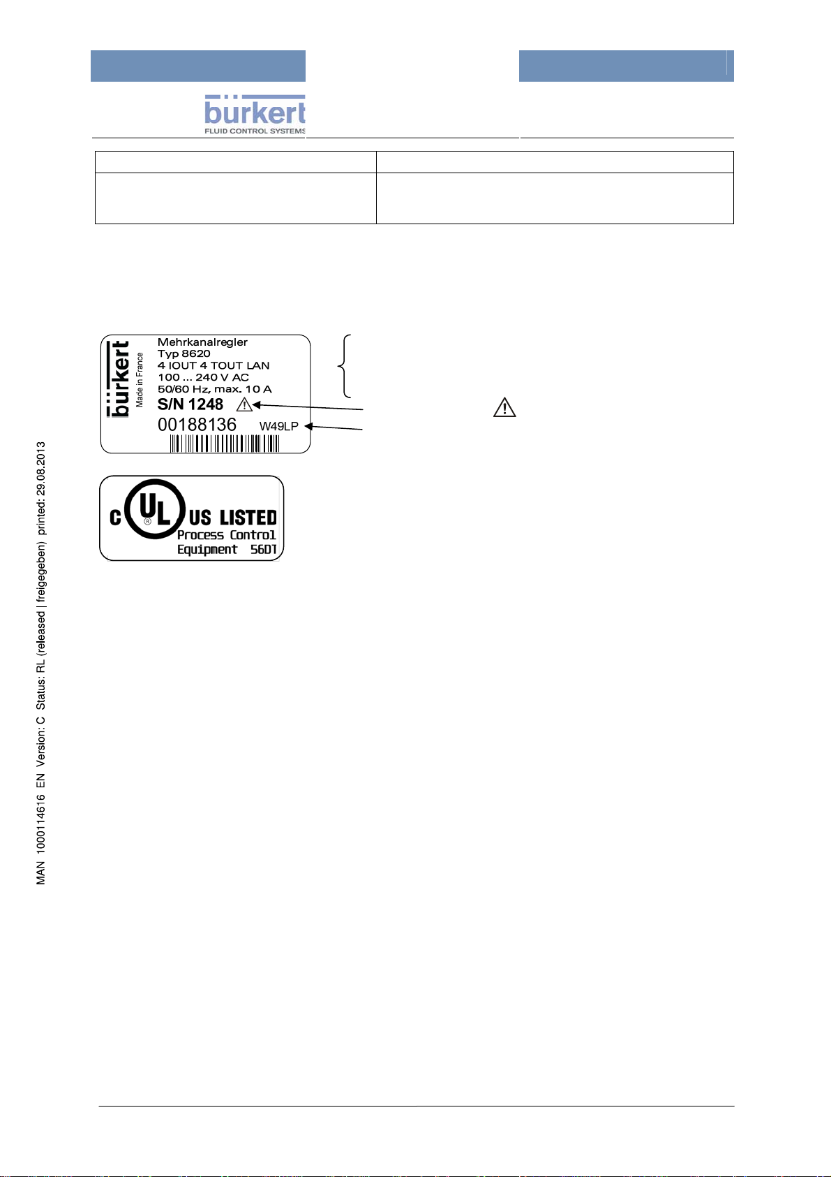
6.2 Type Plate – Example
Device designation (multi function controller)
Type
Specifical Configuration of the device
Voltage and Frequency range, admissible Current
Serial Number and
Order Number and Production Code
The UL Mark is necessary for marketing at the US and
Canadian market.
Attention! Consider the manual!
This UL Mark certifies that the appropriate safety
requirements are observed (for UL approved versions
only.)
Page 20
Page 21

mxCONTROL Type 8620
6.3 Hardware Structure
This simplified block diagram shows the main hardware components of „Type 8620 mxCONTROL“.
Figure 1: Block diagram - Hardware structure
The number of the in- and outputs of the several hardware versions is listed in the following
Table 2:
Inputs
Outputs
Analog 4 … 20 mA - 4
Analog Pt100 - 2
Analog 4 … 20 mA or Pt100 4 -
Digital (Binary) - 4
Digital (Binary or Frequency) 4 4
Analog 4 … 20 mA 4 (optional) 2
Relay 5 5
Transistor 4 (optional) 2
Table 2: Number of inputs and outputs of the hardware versions
Hardware version 1 Hardware version 2
Page 21
Page 22

mxCONTROL Type 8620
6.4 Module Overview
This table shows the available standard modules which can be combined specifically for the
application. They can function either as process or control or merely as display module.
The module names as used in the configuration files and the short designations for the menu are
listed as well as a short explanation of the module type.
Module-name for XMLconfiguration-file
NONE -- --
BATCH Batch Batch-Dosing
BIOCIDE_DOSING BioDos Biocide-Dosing
CL_ORP CL/ORP Chlorine/Redox-PI-Control
COMMON_PID PID General PID controller
COND_CONTROL Cd Conductivity On/Off control
COND_CONTROL_RATIO Cd r
COND_PI Cd-PI Conductivity PI-Control
COND_PI_RATIO Cd-PIr
CORROSION_DISPLAY CorroD Corrosion-Display
MONITOR_PV Mon PV
O2_SCAV_CTRL_RATIO O2SCR
OPEN_PROP OpProp Dosing (proportionally to process value)
PH_ACID_CAUS pH-AC pH PI-Control with outputs for acid and caustic pumps
PH_ ACID_OR_CAUS pH-A/C pH PI-Control with output for acid (or caustic) pump
TOTALIZER Total 2-channel totalizer
Short name in
menu
Module type
Conductivity On/Off control, set point via ratio from Make-Up
Channel
Conductivity PI-Control,
set point via ratio from Make-Up-Channel
Monitoring only up to two process values (data logging) and
optionally output
Dosing of oxygen absorption media based on flow rate and
temperature of the feed water
Table 3: Module designations and types
Page 22
Page 23

mxCONTROL Type 8620
7 Installation
7.1 Safety Notes
DANGER!
Danger from electrical voltage!
Reaching into the system presents an acute risk of injury.
Always switch off the power before beginning with the work activities and secure it against being
switched back on inadvertently!
Obey the applicable accident prevention and safety regulations for electrical devices! Please, compare
the DANGER and UL indications in chapter 7.4 “Electrical Connections”!
WARNING!
Danger from improper installation!
Improper installations may result in injuries as well as damages on the device and its environment.
This type of work may only be carried out by authorized technical personnel and with suitable tools!
Danger from unintentional operation!
Dangerous situations may develop from unintentional operation of the plant.
Prevent the possibility of unintentional operation of the plant through suitable measures.
7.2 Quick Start Guide
Install the „Type 8620 mxCONTROL“ in a plant or
mounted on a backboard as shown in figure 2
Figure 2:
→ Install the required sensors and other equipment, according to the separate operating
instructions.
→ Make the wiring connections according to the specifications in chapter
→
Switch on the operating voltage.
→ Load the configuration file and the parameter file from an SD card (see chapter
→ Chec
→ Set
k/edit parameters and values in the operating menu according to the menu description
(see Chapter
9) and module description (chapter 14).
the date and time in the corresponding menu (refer to chapter
„Type 8620 mxCONTROL“ - Installation example
7.4.
11.2).
21.5.8).
Page 23
Page 24

mxCONTROL Type 8620
7.3 Mechanical Installation
Direct sunlight will reduce the viewing contrast at the display – although it is harmless to the
display. Therefore find a suitable, protected location for the installation.
The „Type 8620 mxCONTROL“ is not designed for ambient temperatures below.0 °C.
If this cannot be avoided, the „Type 8620 mxCONTROL“ must be installed in a
thermostatically controlled cabinet to maintain a normal ambient temperature.
In North America, the device must not be installed directly at building walls! In this case use
always appropriate backboards or switchboards/switching cabinets for mounting the device.
→ Open the cover (unlock it if a key is supplied) by pressing the snap lock with both thums.
For closing the cover press it down until a “click” is to be heard (and lock it with the key).
→ The „Type 8620 mxCONTROL“ is designed for wall mounting (exception: North America – see
information frame above).
Figure 2 shows the preferred mountin
g position.
Drill 4 holes (according to
the used screws) according
to the dimension shown.
Mount the device with 4 appropriate screws
(recommended screws:
M4.5 or M5,
screw head: ≤ 9.5 mm).
Figure 3: Dimensions for mounting
4 Mounting holes
→ Wall mounting with screws is made possible by 4 openings located in each corner of the
enclosure (see
Figure 3). Access to these openings is obtained by opening the cover.
7.4 Electrical Connections
DANGER!
Danger from electrical voltage
Reaching into the system presents an acute risk of injury.
Make sure that no supply voltage is present on the device when working on it! Obey the applicable
accident prevention and ensure that all electrical connections comply with local and plant regulations!
Pay attention to correct design of the fuse and/or the line safety switch in the power supply
line.
For dimensioning and installation of disconnecting switch, fuses etc. necessarily refer to further
information below!
In North America, devices with UL certification have to be used for these purposes.
Page 24
Page 25
mxCONTROL Type 8620
Dimensioning of fuses, line safety switches, overcurrent protection devices
Pay attention to correct design of the fuse and/or the line safety switch in the power supply line.
The L- and N-conductors have to be protected with overcurrent protection devices (max. 10 A) as e.g.
fuses, line safety switch etc.
Also install an equipment for the disconnection of L- and N-conductors from the power supply
near the „Type 8620 mxCONTROL“. Therefor e.g. the above-mentioned overcurrent protection
device or an appropriate disconnecting switch (110/240 V and with at least the size of current of the
overcurrent protection device) can be used.
If the sum of extracted current of all connected actuators at the Power Supply part exceeds the
value of 10 A, the actuators can be connected with a separate voltage supply for those actuators -
please refer to the schemata in appendix
21.2 „Power Supply of Actuators/Sensors“.
Electrical Connections
The preferred mounting position for the „Type 8620 mxCONTROL“ is with the cable glands facing
downward, i.e. all cable glands are located at the bottom of the device.
→ The electrical connections can be accessed by loosening the screws that hold the lower cover
plate in place. You can then lift the cover plate by the black handle.
→ The terminal strips for the mains voltage level (power supply) and the low-voltage level
(instrumentation supply) are separated by an isolating plate (see
Mains voltage level
(Power supply PS)
(Hardware version 1)
Figure 4).
Low-voltage level
(Instrumentation
supply IS)
Isolating plate
(Hardware version 2)
Figure 4: Viewing the inside of the terminal strip compartment (with the cover plate removed) of the
„Type 8620 mxCONTROL“:
top: Hardware version 1: Screw terminals
bottom: Hardware version 2: Spring type terminals
→ Use suitable cables (for wire gauges/cross sections see chapter 7.5) for the passage through the
cable glands (for outside cable diameters and thermal stability of cable material refer to chapter
6.1, paragraph “Electrical connections”).
→
Unscrew the nut of cable gland and remove the seal.
→ First push the cable through the nut of the cable gland and the seal insert and then prepare each
wire of the cable with a cable end sleeve (see
(cable for Power Supply: sleeve length: 7 mm,
Figure 5) of the recommended length:
cable for Instrumentation Supply: sleeve length: 5 mm).
Page 25
Page 26

mxCONTROL Type 8620
Figure 5:
Cable with cable end sleeves
→ Then guide the prepared cable through the cable gland opening into the device and attach the
wires to the terminal strip.
→ Now screw the cable gland nut tight until the cable is securely attached
(tightening torque for cable gland M16: max. 6 Nm
(tightening torque for M20 cable gland: max. 8 Nm
(tightening torque for M20 cable gland: max. 10 Nm)
→ After clamping all required connections re-attach the plate and tighten the screws.
Important! Seal unused cable glands with sealing bolts – protection class IP65 is otherwise
not guaranteed.
7.5 Terminal Strip Pin Assignment
7.5.1 Power Supply (PS)
Connect the cables as shown in the PIN tables in the appendix (21.3.1 and 21.4.1).
The respective terminal assignment plans are created with the PC Tool according to the “project”.
They serve as basis for wiring diagrams and the input/output assignment as shown in the example in
the appendix
Hardware version 1
Figure 6: Terminal strips for the mains voltage level, with PIN numbers
21.1
Hardware version 2
Hardware version 1 Hardware version 2
PIN numbering 1 to 48 1 to 36
Terminal strips Screw terminals Spring type terminals
Terminal grid 5.08 mm, AWG 26 … 14 5.0 mm, AWG 24 … 12
Wire gauges - rigid wires 0.14 … 2.5 mm² 0.2 … 4.0 mm²
Wire gauges - flexible wires 0.14 … 1.5 mm² 0.2 … 2.5 mm²
Tightening torque for screws 0.5 … 0.6 Nm (4.5 … 5.3 lb in) --
PIN table Table in appendix 21.3.1 Table in appendix 21.4.1
Page 26
Page 27

mxCONTROL Type 8620
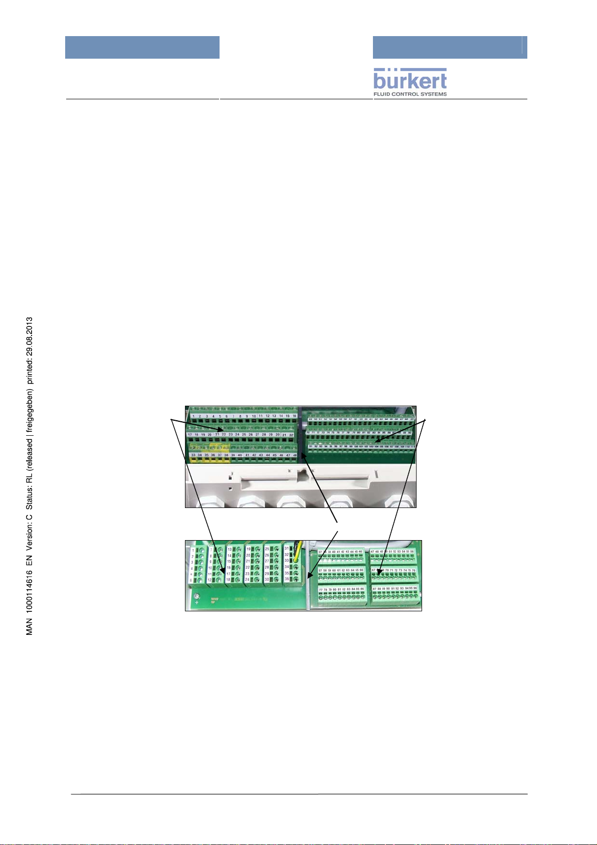
7.5.2 Instrumentation Supply (IS)
Connect the cables as shown in the PIN tables in the appendix (21.3.2 and 21.4.2).
The respective terminal assignment plans are created with the PC Tool according to the “project”.
They serve as basis for wiring diagrams and the input/output assignment as shown in the example in
the appendix
Hardware version 1
Figure 7: Terminal strips for the low voltage level, with PIN numbers
21.1
For sensor inputs and analog 4…20 mA outputs shielded cables are recommended for best
EMC. Connect the cable shields with the respective Pin “GND” for EMC.
Hardware version 2
Hardware version 1 Hardware version 2
PIN numbering 49 to 111 37 to 96
Terminal strips Screw terminals Spring type terminals
Terminal grid 3.81 mm, AWG 26 … 16 3.5 mm, AWG 24 … 16
Wire gauges - rigid wires 0.14 … 1.5 mm² 0.2 … 1.5 mm²
Wire gauges - flexible wires 0.14 … 1.0 mm² 0.2 … 1.5 mm²
Tightening torque for screws 0.22 … 0.25 Nm (2 … 2.2 lb in) --
PIN table Table in appendix 21.3.2 Table in appendix 21.4.2
7.6 Download of a Configuration and Parameter File
A configuration file must be downloaded to the „Type 8620 mxCONTROL“ before it can be effectively
used in an automation system. Downloading of configuration files is for the Specialist Level only!
After successful download of the configuration file the parameters will be set back to the default
values. With the download of the corresponding parameter file the default values will be overwritten
with these values.
Read chapter
8 and especially chapter 11.2 before.
Page 27
Page 28

mxCONTROL Type 8620
8 Description of Human-Machine Interface
8.1 Safety Notes
WARNING!
Danger from improper operation!
Improper operation may result in injuries as well as damages on the device and its environment.
The device may only be operated by authorized technical personnel!
The persons operating the device must be familiar with the content of the operating instructions and
have understood the same. The safety instructions and intended use require special consideration.
8.2 Operating and Display Elements
Hinged lid protection for
the USB-Interface and
SD card-slot
(SD card will be ejected
by pressing it)
A/M-Key - switches
between automatic and
manual mode, with
flashing alarm-LED
Display
4 soft keys.
(the functions change as
shown in the lowest line
of the respective
display)
handle for lifting the
cover plate
Figure 8: View on the panel of „Type 8620 mxCONTROL“
The „Type 8620 mxCONTROL“ is operated with 4 soft keys below the display (with alternating
functions) and an A/M key to switch between automatic and manual mode.
The brightness of the display can be changed. The brightness can be adjusted in 10 brightness
levels under the main menu item "System settings"; refer to
The default setting is brig
htness level 5 to ensure a long service life of the display.
Table 4 in chapter 9.1.
Page 28
Page 29

mxCONTROL Type 8620
8.3 Operation Mode
8.3.1 Automatic & Manual Mode Key
A/M key with
yellow LED
In case of alarm, follow the descriptions in chapter 15 “Alarm and Error Messages”.
8.3.2 Automatic Mode (LED on)
The „Type 8620 mxCONTROL“ starts in automatic mode after powering up. The LED is on; a "running
bar" in the top line of the display also indicates the Automatic Mode.
The A/M key switches between the Automatic and Manual Mode;
the A/M key includes a yellow LED:
LED on Æ Automatic Mode
LED off Æ Manual Mode
LED flashing Æ ALARM (at least one alarm) both in
automatic and manual mode
8.3.3 Manual Mode (LED off)
The operating mode for all modules can be changed directly by pressing the separate A/M-Key.
Attention: All dosing processes of the Batch- and Biocide-Dosing-Modules are cancelled
in Manual Mode!
(The next dosing process will start at its programmed time when returning to Automatic Mode.)
In manual operation, the control of the process values is transferred from the device to the user. The
user now controls the process values manually with the soft keys of the „Type 8620 mxCONTROL“
whereby the connected actuators are operated. For this purpose, the values in the main menu
"Process data" need to be changed under the corresponding module.
Switching from Automatic to Manual Mode is “changeless”, except for the "Biocide-Dosing" and
"Batch" modules. “Changeless switching” means that the last output value in Automatic Mode is the
current output value in Manual Mode as long as the operator does not change the output value
manually.
If the system switch override function or the flow switch override function or the
safety output value is activated the manual output value will be reset to “0”!
Page 29
Page 30

mxCONTROL Type 8620
8.4 Layout of Menu Screens
Running bar directly below the upper horizontal screen border, running
from the left to the right – indicates the Automatic Mode
Cursor bar
Menu items
Current position inside
the whole menu tree
4 Soft keys
Menu title - indicates the (self selected) designation for the
BW 06
Processdata
Parameter
Configuration
System settings
1
ENTER
“project” (module combination)
(or "No Config. loaded", if no
configuration file is
downloaded)
Current cursor position within
the current menu (slide bar)
The soft keys at the device have no symbols. Their function is defined
in the bottom screen line, where the current function of each key is
displayed as a text string or as a symbol.
The keys have symbols to explain the possible actions, in the above
example:
no function, up-arrow, down-arrow, Enter
The current position inside the menu tree is shown in the middle of the
bottom screen line.
You can scroll through the menu with the "up-arrow" and "down-arrow"
soft keys.
The menu position/numbering is indicated by the main menu and max.
4 submenus, i.e. it is a max. 5-character alphanumeric combination and
is shown in the following format: "4-A-3-1-2".
(the numbering of the menu items within the menu goes from 1 to 9,
higher positions are continued with capital letters because of the limited
space in the display:
from "A" (=10), "B" (=11) to "Z" (=35).
The font size of the current position string depends on the number of
submenus to be displayed.
Cond Control
The trend of the process value PV from standard (4...20 mA) and
frequency signal inputs is shown as chart and regularly updated.
The example shows a trend chart of set point SP and process value PV -
EXIT HOLD
SP/PV
the inscription ("SP/PV") only names the trend chart without identifying
any soft key.
“HOLD“ freezes the display (“CONT” continues displaying the trend.)
Page 30
Page 31

mxCONTROL Type 8620
9 Menu Structure
9.1 Principle of Menu Tree Structure
A welcome message appears in the display after switching on the „Type
8620 mxCONTROL“. This display content is then shown with the current
software version number for approx. 4 seconds.
When starting the „Type 8620 mxCONTROL“ for the first time, the next
display text shows "No Config. loaded", i.e., no (configuration/parameter)
files have been downloaded yet. In this case, refer to chapter
downloading configuration and parameter files.
The menu of „Type 8620 mxCONTROL“ contains 8 main menu items; its
submenus are used to display and set variables and parameters.
The first number in the bottom line of display is the number of the active
main menu item (items 1 to 8).
Depending on the hardware version, the „Type 8620 mxCONTROL“ has digital and analog inputs
which can be configured according to the user requirements.
The configuration via the configuration file is needed for enabling and labelling the desired inputs and
outputs and for activation of special input functions. The scaling, filter and alarm settings can be done
with the configuration file, too, but also directly at the „Type 8620 mxCONTROL“ device.
11.2 about
The main menu and submenu items for a “project” (module combination) with freely selectable name
(in this case "BW 06") are listed in the appendix (
of the menu tree an
d illustrates the structure of the menu.
21.4.3 ff). The following figure shows exemplified part
Figure 9: Structure principle of the menu tree
Page 31
Page 32

mxCONTROL Type 8620
A similar structure is given for all “projects”.
The main menu items contain submenus as exemplary listed below:
Main Menu Submenus
1 Processdata
2 Parameter
(CodeLevel:
Operator)
3 Configuration
(CodeLevel:
Specialist)
4 System settings
5 Upload/Download
(CodeLevel:
Operator/Specialist)
6
Data logging
(CodeLevel: Operator)
7
Calibration
(CodeLevel:Specialist)
8
Clock
(CodeLevel: Operator)
(*) function – refer to chapter 11.1 „Functional Overview“
Display of the process values depending on the current configuration:
Inputs and outputs, module-specific process data displays:
1-1 Inputs
1-2 Outputs
1-3 Cond Control (module in function (*) 1)
1-4 O2 Scav Ctrl (module in function (*) 2)
…
1-A (module in function (*) 8)
Access to the parameters of the configured modules:
2-1 Cond Control
2-2 O2 Scav Ctrl
2-3 Batch-Dosing
…
Access to the configuration data of the configured inputs, outputs and modules. Also
access to Alarm Output, System Switch and Flow Switch configuration and to Codes:
3-1 Inputs
3-2 Outputs
3-3 Modules
3-3-1 Cond Control (module in function (*) 1)
3-3-2 O2 Scav Ctrl (module in function (*) 2)
…
3-3-8 (module in function (*) 8)
3-3-9 System Switch
3-3-A Flow Switch
3-3-B Alarm
3-4 Codes
Language selection, display inversion, factory reset (CodeLevel: Specialist), Device
information (with Firmware revision, Number of restarts, Restart function (CodeLevel:
Specialist)):
4-1 Language
4-1-1 German
4-1-2 English
4-1-3 French
4-2 Display
4-2-1 normal
4-2-2 inverse
4-2-3 brightness
4-3 Factory Reset (CodeLevel: Specialist)
4-4 Device info
4-5 Network info (CodeLevel: Operator, available only for devices with Ethernet
Option)
Upload / Download of
- Configuration file (Specialist level)
- Parameter file (Operator level)
from / into „Type 8620 mxCONTROL“ via SD card:
5-2 Download
5-3 Upload
Start / Stop of data logging on SD card, Setting of data logging sample time (Tsample),
log file options and event log settings (CodeLevel: Specialist).
User calibration of 4-20mA inputs and 4-20mA outputs
Setting time and date.
Table 4: Main menu and submenu items (in the example for "BW 06")
Page 32
Page 33

mxCONTROL Type 8620
9.2 Setting Numeric Values
Parameters, i.e. their numeric values can be changed within predefined ranges. They are described in
the following chapters. Not all numeric values allow to move the decimal point.
The operator has to select the variable or parameter he wants to change with the soft key “ENTER”.
Before the operator can change the value of a parameter, he has to enter the correct password. To
change values from the main menu items "Parameter" or "Configuration", the password needs to be
entered only once. For changing parameters from process data level, the operator has to enter the
correct password every time he wants to change a variable.
(Compare also chapter
→
If the password protection is passed, a special input screen is displayed. In this screen either the
decimal point (if available) or the lowest numeral or character will be automatically selected as
the first cursor position.
→ The current cursor position is always displayed in inverse colour. It can be changed step-by-
step by pressing the key “<-“.
→ If the decimal point is selected by the current cursor position, it can be moved step-by-step to the
left by pressing the soft key “+”.
→ Change the value of a selected numeral/character by pressing the key “+”.
→ Cancel the whole setting process by pressing the key “ESC” (Escape).
→ Confirm the whole setting process by pressing the key “ENTER”.
→ After leaving the setting process by pressing the key “ESC” or “ENTER” the original menu
screen is shown again.
10.)
Important!
The new parameter/configuration data will be saved only after returning to the main
menu – a short message thereby shows “Save in EEPROM”.
The password protection only becomes active again after returning to the main menu!
Return therefore to the main menu after completing the changes!
In the following example soft key 1 is “ESC”, key 2 is “+“, key 3 is “<-” and key 4 is “OK”.
Soft key 1:
Soft key 2:
Soft key 3:
Soft key 4:
ESC
+
Å
OK
Soft key 1 2 3 4
Page 33
Page 34

mxCONTROL Type 8620
10 Password Protection
Three authorization levels (CodeLevel) are provided for the operation of „Type 8620 mxCONTROL“:
General access, access for operators, access for specialists.
A password is a 4 digit number. The operator has to enter the password of the required protection
level in order to enter protected menus or menu items.
The specialist password also overrides the operator password.
A separate description on how to change the password is provided below.
Following user operations are password protected – see also table below:
• Editing parameters / configuration data
• Download/upload of parameter/configuration files
• User calibration of 4-20mA outputs
• Changing passwords
• Factory Reset
• Software Reset
• Data Logging
• Clock setting
Note! The "Master" password cannot be changed. The user of this password is granted
access to all protected code levels. This Master Password is available at Bürkert Service.
Protection
Level
0
1
2
Table 5: Password protection – different levels
User Notes
Generell/normal process level:
Current process and control outputs are displayed.
Following actions are allowed:
• Changing the operating mode of the „Type 8620 mxCONTROL“ between
General
access
Operator
(Factory
set:
Code: 0001)
Specialist
(Factory
set:
Code: 0002)
automatic and manual mode.
• Changing values in manual mode
• Acknowledgement of Alarms (e.g. Maximum Output Timer) and messages.
• Operating Language
• Display-Mode
In addition to protection level 0 the following actions are allowed:
• Parameter access
• Up- and Download of parameter files
• Data Logging
• Setting Up Real Time Clock
In addition to protection levels 0 and 1 the following actions are allowed:
• Configuration access
• Up- and Download of configuration files
• User calibration of 4-20mA outputs
• Changing Passwords
• Factory Reset
• Software Reset
Page 34
Page 35

mxCONTROL Type 8620
Changing Passwords
→ Choose the main menu item “Configuration”, enter with “ENTER”
→ Enter the specialist password (by possibly pressing the "+" key several times; you can also use
the "<-" for multi-digit numbers), then press "OK".
→ Scroll for Menu item “Codes” with the “Arrow”-keys, enter with “ENTER”
→ Choose the Operator or Specialist Level which shall be changed, then press key “INPUT”
→ Input the specialist code by pressing the key “+” the required number of times, then press “OK”
→ Set a new value for the code by pressing the key “+” (for multi-digit codes use also the key “<-“),
then press “OK”.
If the menu item was left by pressing key “ESC” the new value is not accepted!
→ Leave the Menu item “Codes” by pressing “EXIT”
Page 35
Page 36

mxCONTROL Type 8620
11 General Software Concept and Functions
11.1 Functional Overview
The „Type 8620 mxCONTROL“ is a configurable multifunction controller. Its principal of function can
be divided into three main process areas:
Input process, control process and output process (see
Figure 10).
Figure 10: Process diagram
Input Process:
• Reading of the enabled inputs and the processing of scaled process values from raw values.
• alarm functionality for each of the inputs - except binary and pulse counter inputs
Control Process:
• Simultaneous activity of up to 8 Control Functions (further on named Function)
• Available modules in the device (see chapter
s
everal times as function with its own configuration and parameter data – considering the
14 „Controller Modules“) can be used also
required resources. The very data-intensive module „BIOCIDE_DOSING" can be used only 1
times, for example
• Each function can be configured to work as one of the available modules (see chapter
the stru
cture of the function allows
• Each function can contain modules with few module inputs and outputs. But only spezial
functions can work as modules with many in- and outputs
• The in- and outputs of the functions will be linked by means of the PC Tool
14) – if
Page 36
Page 37

mxCONTROL Type 8620
Most modules have a spezial ”Output Override“-Function (override the original output value) in
order to react to situations as:
- Input or Sensor Faults,
- Activation of the System or Flow Switch or
- special states or alarms of other activ modules.
Output Prozess:
• Converting and transferring of the virtual module outputs to the configured real outputs (that
means the real outputs are controlled to output the configured form of output signal)
11.2 Up- and Downloading of Configuration/Parameter Files
11.2.1 Download
Before the „Type 8620 mxCONTROL“ can act in an automation system, a configuration file
must be downloaded to the device (e.g. from the SD card).
(The last downloaded configuration and parameter file defines the function of the „Type 8620
mxCONTROL“!)
This is for the Specialist Level only!
Up-/Download processes on SD-Card are only possible if Data Logging is disabled.
For the Download process proceed as stated below
(see also the sample menu tree in the appendix
→ Supply the „Type 8620 mxCONTROL“ with power
→ Insert an SD card (formatted with FAT16) into the interface (SD card slot)
21.5.6):
under the hinged lid
→ Scroll in the main menu to the menu item “Up-/Download” (via “arrow” keys),
press key “ENTER”.
→ Enter the correct password (via keys „+“ and „<-“)
(specialist password for configuration files,
operator or specialist password for parameter files).
→ Select “Download”, press key “ENTER”
→ Navigate via arrow keys to file folder containing the desired configuration or
parameter file.
Return to parent folder by scrolling to ".." or
open a folder by pressing the key "ENTER".
To furnish the „Type 8620 mxCONTROL“ with a new configuration, first
the configuration file must be downloaded to the device, followed by the
corresponding parameter file.
Page 37
Page 38

mxCONTROL Type 8620
→ Select the desired configuration file "XXX.cfg" for download into the „Type
8620 mxCONTROL“, press key "ENTER".
Download of the configuration file is running. If the download was successful, the
message "Successful" appears in the display.
→ Return to submenu by pressing key "EXIT".
→ Select associated parameter file “XXX.par”, press key "ENTER".
Download of the configuration file is running. If the download was successful, the
message "Successful" appears in the display.
→ Return to submenu by pressing key "EXIT".
→ Leave the submenu by pressing key “EXIT” (several times).
Remove the SD card by pressing against it.
11.2.2 Upload
For saving parameter/configuration files use the function “Upload”.
Comments in a downloaded xml-file will not be stored in „Type 8620 mxCONTROL“ – when
uploading a file no comments are included!
Up-/Download processes on SD-Card are only possible if Data Logging is disabled.
For the Upload process proceed as stated below
(see also the sample menu tree in the appendix
21.5.7)
→ Supply the „Type 8620 mxCONTROL“ with power
→ Insert an SD card (formatted with FAT16) into the interface (SD card slot)
under the hinged lid
→ Scroll in the main menu to the menu item “Up-/Download” (via “arrow” keys),
press key “ENTER”
→ Enter the correct password (via keys „+“ and „<-“)
(specialist password for configuration files,
operator or specialist password for parameter files)
→ Select “Upload”, press key “ENTER”
→ Select “Param-File” (operator or specialist level)
or „Config-File“ (for specialist level only) by pressing key “START”.
The device saves the file to the current folder (marked by a single dot ".") after
pressing the key "ENTER" or
scroll to another folder and press key "ENTER".
The device either uses the name of the last file loaded or creates a new internal
name for the file by extending with “vXX”. (XX is running from 01 to 99).
To overwrite an existing file with new data, select the desired existing file, press
key “ENTER”. It appears a request for overwriting:
→ Press “YES” for overwriting the selected file,
→ press “NO” for creation of a new file name (with extension vXX) or
→ press “EXIT” to stop/cancel the upload process
Page 38
Page 39

mxCONTROL Type 8620
Stopping/cancelling of the upload process – by pressing key „EXIT“ -
makes the uploaded file incomplete and it cannot be used for a download
process.
But only at next download process appears the error message!
And if upload process was successful the display shows the notification
“Successful”.
→ Leave the submenu by pressing key “EXIT” (several times). Remove the SD
card by pressing against it.
11.3 Data Logging
The "Data Logging" function
• stores all important process values for reading, checking and archiving
• has to be activated/enabled for that functionality
• logs the data cyclically according to the set data logging sampling time "Tsample"
• logs the data event-triggered (for details refer to “
Each time the internal (volatile) 512-Byte-memory is filled, its content will be attached at the end of the
datalog file on the SD card (formatted with FAT16) and will be saved then.
The Data Logging continues
Event Triggered Data Logging Function”)
• as long as the data logging function is activated
• as long as the SD card is filled - which causes an error message on the display
• as long data can be saved on the SD card - if the logged data cannot be written (anymore) to
the SD card, data logging will be stopped and a corresponding error message is shown on the
display.
The "Tsample" sample time has a factory setting of 3600 seconds.
If the selected sample time is too short, an excessive data volume will be produced and may
fill the memory capacity of the SD card very fast.
Therefore select a sample time that enables the SD card to be written with the data until the
next change of the SD card or use an SD card with higher capacity (described in next section).
A new set sample time gets active when returning to the main menu.
No Up-/Download processes on SD-Card are possible if Data Logging was active.
The data is stored into the current log file “8620-DEV_ID-DEV_SERIAL-INDEX.log”:
with: DEV_ID device ID number (8 digits with leading zeros)
DEV_SERIAL device serial number (7 digits with leading zeros)
INDEX log file index (00001...65535) (5 digits with leading zeros)
The current log file name is displayed in the menu “Data logging\Logfile\” under the item “Current”.
The log file index “INDEX” can be increased manually by the operator in the same menu with the item
“New logfile” (CodeLevel Operator) – in this case a new log file is started.
If data logging was disabled the log file index can be adjusted (CodeLevel: Specialist); e.g. in order to
restore manually the old log file index after a firmware update or a factory reset.
The data can be selected, indicated, edited with PC and also archived externally if necessary.
Page 39
Page 40

mxCONTROL Type 8620
Log files are stored in the root directory of the SD card. The root directory can contain
approximately max. 100 entries (files and folders; each file / folder name has max. 31
characters).
The layout of the data logging file, the abbreviations and the coding used in the header are shown
in an example in appendix
21.6.
Automatic log file size limitation (FSizeLimit = Yes)
A new log file is started automatically by increasing the log file index,
if data logging was active and the current log file size exceeded the maximum log file size FSizeMax.
Back up older log files in time from SD card on PC. If permitted, delete them afterwards on SD
card.
Event Triggered Data Logging Function
An integrated Event Triggered Data Logging Function logs a complete set of process data with
max. 10 s delay, after a specific event was triggered.
Such specific events are:
• Occurrence / Disappearance of an alarm.
• Occurrence of important error messages
- Battery Failed / RTC Failed / Check Clock!
- Eeprom Fault XXY
- Error ISR timing!
- Calibdata Fault 4-20mA In / Pt100 in / 4-20 mA Out
- 4-20mA Out X failed
• Changing operational mode (Automatic / Manual)
• Switching on/off of an output, which is configured as an On/Off output
• Communication events and errors (devices with Ethernet Option only)
- Start / end of incoming / outgoing connection
- Changes of net link status
- Important communication error messages
• Miscellaneous events
- Totalizer reset
- Start / end of user calibration of 4-20mA inputs / outputs
The event triggered data logging function can be enabled / disabled and configured by means of
configuration. For details refer to section “Configuration”.
Datalog failed alarm
If data logging failed (e.g. in case of writing error or full/missing SD Card), a special datalog alarm is
raised and the common alarm is actuated, too.
This special datalog alarm needs to be reset in the data logging menu by the operator.
Page 40
Page 41

mxCONTROL Type 8620
Parameter (CodeLevel: Operator)
Parameter
Access via
Datalogmenu
Access via
XMLParam.-File
Abbreviation
(menu)
Datalog Logging SD-Card rw -- -- enable/disable
Sample Time rw rw Tsample 10 ... 99999sec 3600sec (*)
Logfile
Current log file name r -- Current -- --
Increase log file index by
one (Creates new log file)
Automatic log file size
w --
New
Logfile
rw rw FSizeLimit Yes / No No
limitation
Max. log file size rw rw FSizeMax 0.1 … 100.0 MB 1.0 MB
(*) Default value also after successful download of Cfg-File
Range
Default values
(after factory reset or at
start of Param-FileDownload)
Disable (only after
factory reset)
-- --
Configuration (CodeLevel: Specialist)
Configuration
Access
via
Datalog-
Access
via XMLCfg.-File
Abbreviation
(menu)
menu
Log File
Log file index (**) rw -- LFI 1 … 65535
EventLog
Event Log function rw rw EventLog On, Off On
Log Events (*)
Alarms rw rw Alarms On, Off On
Important error messages rw rw ErrorMsg On, Off On
Switching Operational
rw rw OpMode On, Off On
Mode
Switching of On/Off
rw rw O/O outputs On, Off On
outputs
Communication events /
rw rw Comm On, Off On
errors
Miscellaneous rw rw Misc On, Off On
(*) Only displayed, if Event Log function was set to On.
(**) Only displayed, if Datalogging was disabled
Value range
Default values
(after factory reset or
at start of Cfg-FileDownload)
1 (only after factory
reset)
Page 41
Page 42

(
mxCONTROL Type 8620
11.3.1 Selection of SD card size for Data Logging purposes
The size required for one process data sample depends on the current configuration and the sample
time. Every Tsample seconds a new sample of process data is written into the internal volatile Data
Logging memory.
Required free memory
in [kByte]
with
()
LogsPerDay
Tsample
86400
s
NOE
+=
)
kByte1024HeaderDataNOCSampleDataDaysLogsPerDay +∗+∗∗=
NOE
“Number Of trigger Events per day” which forces a new
process data sample to be written.
Event
Days
SampleData
NOC
Tsample
For trigger events refer to above section “
ered Data Logging Function”.
Trigg
Data Logging Sample Time in seconds
Number of Days to be logged
See below
"Number Of Changes": Number of events requiring a
new "header" in the data log file
HeaderData
86400 s
See below
= 24 h = 1 day
Required free memory
in [MByte]
= Required free memory
in [kByte]
MByte 1
∗
kByte1024
It is:
SampleData - storage capacity required on the SD card to log 1 process data sample after Tsample
has run down and
HeaderData - storage capacity required on the SD card to log 1 header + 1 process data sample.
That means, a new header and a current process data sample is written each time, when:
• enabling the Data Logging
or if Data Logging already is enabled:
• returning to the Main Menu after configuration and/or parameter were changed
• the download is finished successfully / is cancelled / failed
SampleData in [kByte]
HeaderData in [kByte]
with
Page 42
= 0.05 kB * (2 + Number of modules)
= 0.4 kB
Number of modules:
(1.5 + Number of modules) + SampleData
*
Number of active modules.
Page 43

mxCONTROL Type 8620
Estimation for a blank SD card, formatted with FAT16 file system:
Required SD card size [MByte]
Free SD card memory [MByte]
≥
0,9
][MBytememory free Required
, resulting in:
][MBytesize cardSD0,9 ∗=
Estimation, how many days the SD card will suffice:
Days =
kByte 1024
⎛
⎜
⎝
MByte) 1[MByte]memorycardSDFree
∗
MByte 1
SampleDataLogsPerDay
⎞
()
⎟
⎠
HeaderDataNOC
∗−∗−
Example:
An empty 64MByte SD card, formatted with the FAT16 file system,
with a free SD card memory of 0.9 * 64 MByte can receive the logging of process data of
4 normal modules (SampleData = 0.3 kB, HeaderData = 2.5 kB) at an estimated number
of 1000 NOC (Number Of Changes = special events):
- with disabled event triggered datalog function:
- approx. 21 days with TSample = 10 sec or
- approx. 3.5 years with TSample = 600 sec = 10 min
- with enabled event triggered datalog function and estimated number of 1000 NOE (Number Of
trigger Events per day – corresponds approx. with switching on and off each of the 4 module outputs
5 times per hour):
- approx. 19 days with TSample = 10 sec or
- approx. 5 months with TSample = 600 sec = 10 min
11.3.2 Start of Data Logging (enabling)
To enable the Data Logging function proceed as stated below.
An example for the data logging layout can be seen in appendix
→ Insert an SD card (formatted with FAT16) with enough free memory into the
SD card slot under the hinged lid
→ Scroll in the main menu to the menu item “Data Logging” (via “arrow” keys),
press key “ENTER”.
→ Enter the operator or specialist password (via keys „+“ and „<-“)
→ Select „Enable“ of Data Logging, press key "SELEC"
The Data Logging function is activated immediately!
The active function is indicated by a symbol top left on the display.
It is now possible to select another menu item (except Up-/Download)
because the Data Logging function is running in the background until
being disabled.
21.6.
Page 43
Page 44

mxCONTROL Type 8620
Changing sample time:
→ Select „Tsample“, press key “INPUT”
→ Input a new value for „Tsample“ (via keys „+“ und „<-“), press key „OK“
New settings of Tsample apply when returning to the main menu!
→ „ESC“ cancels the function of setting a new value for Tsample,
the new value for Tsample will not be applied.
→ Leave the submenu by pressing key “EXIT”.
Do not remove the SD card if the Data Logging function is active!
Otherwise the logged data could be lost and the directory structure of the SD card could be
damaged up to a non-readability of the SD card.
When changing the SD card the Data Logging has to be enabled again (notice the symbol
top left on display).
11.3.3 Stop of Data Logging (disabling)
To disable the Data Logging function proceed as stated below.
→ Scroll in the main menu to the menu item “Data Logging” (via “arrow” keys),
press key “ENTER”.
→ Enter the operator or specialist password (via keys „+“ and „<-“)
→ Select „Disable“ of Data Logging, press key "SELEC"
The Data Logging function is deactivated immediately!
The symbol top left on the display vanishes.
→ Leave the submenu by pressing key “EXIT”.
Remove the SD card for processing of the file on a PC.
Page 44
Page 45

mxCONTROL Type 8620
11.4 Configuration and Parameterization
11.4.1 Preface about Configuration/Parameterisation
The configuration (Code Level: Specialist) can be done with a special configuration file (XML
style), which can be downloaded into the „Type 8620 mxCONTROL“ from an SD card or via USB.
This configuration file will be generated with a special PC Tool.
Figure 11: Diagram of the upload and download of configuration and parameter fil es
This procedure allows an identical configuration of many „Type 8620 mxCONTROL“ devices. It is
also possible to upload a current configuration file from the „Type 8620 mxCONTROL“.
The parameterization can be done separately in the same way.
It is possible to change only the parameterization in the parameter file, e.g. for optimizations and
download it into the device.
Furthermore, the „Type 8620 mxCONTROL“ can be parameterized by using the soft keys. It is also
possible to upload the current parameters from the „Type 8620 mxCONTROL“.
Firmware updates are handled only via USB.
11.4.2 Operating Language
Pre-selection of the operating language is done in the configuration file. The language can also be
changed by an operator in the System settings menu at the device. Available are the languages
English, German, French.
11.4.3 Factory Setting of Parameters and Factory Reset
The command “Factory Reset” deactivates (deletes) th e current configuration and parameterization.
Also the all the parameters and the codes are reset to default values.
Further operation of the „Type 8620 mxCONTROL“ is only possible after downloading a configuration
and parameter file via SD card.
"Factory Reset" is a submenu of the main menu item "System Settings". It is password-protected
(CodeLevel: Specialist).
Page 45
Page 46

mxCONTROL Type 8620
11.5 Communication
11.5.1 USB
Device access via USB allows putting the “Type 8620 mxCONTROL” easily into service.
This functionality is available from Firmware Rev.C.00.00.00.
Functionality
Please refer to chapter 11.5.3 “(Remote) Device access via PC-Tool”.
Configuration (CodeLevel: Specialist)
This configuration menu is located under the menu item “Configuration\Communication\USB“.
Configuration
USB device access
(via PC-Tool)
Access
via Cfg.menu
rw --
Access
via XMLCfg.-File
Abbreviation
(menu)
PCTool
Access
Value range
On, Off On
Default values
(after factory reset)
11.5.2 Ethernet (only devices with Ethernet option)
„Type 8620 mxCONTROL“ devices with assembled Ethernet option offer remote access and email
notification possibilities.
8620
with Ethernet option
DHCP Server
Only required if DHCP
was used for automatic
IP address assignment
Mail Server
For email
notification in
Intranet only
(supports SMTP
without authentication)
PC
For Access to 8620
via Ethernet
(with PC-Tool
8620 running )
10/100 Mbit/s Ethernet with TCP/IP
Intranet
DMZ
(supports SMTP
without authentication)
Firewall
Figure 12: Remote access and Email notification possibility (with Ethernet option)
Page 46
Mail Server
For email notification in
Intranet and Internet
Firewall
Internet
Page 47

mxCONTROL Type 8620
Features
Feature
Operational Speed 10 / 100 Mbps (auto negotiation)
IP address assignment Static (recommended) or dynamic (DHCP).
A DHCP server is required for dynamic IP address.
Email notification For alarm / warning / error and restart information.
Therefore a mail server with SMTP (without authentication) for sending emails to
intranet and internet is required.
(For details refer to “
Device access With Buerkert PC-Tool via Serial Tunnel and TCP/IP over Port 10001.
(For details refer to “
Security - Code protected device login via PC-Tool : CodeLevel + Code
- Automatic logout after 5 minutes of no action (except if remote control was active)
- Automatic disconnection after 5 minutes without login
- No encryption of data transmitted over TCP/IP
- DMZ (Demilitarized Zone) or VPN (Virtual Private Network) are not supported –
therefore an external gateway with the necessary functionality is required.
Email notification”)
Remote device access via PC-Tool”)
Display of Ethernet state
The following list shows the displayed symbols for the current ethernet sta te.
The symbol for the Ethernet remote state is located
in the upper left corner of the display, right beside
the datalog symbol.
Symbol Description
Ethernet function disabled / not supported (devices without ethernet option)
Ethernet function enabled, initializing / checking network status
No network detected
Ethernet ready
Incoming connection (e.g. from PC-Tool)
Outgoing connection (to SMTP mail server)
Update mode active (e.g. for firmware update of ethernet component)
Following additional information can be found in the menu “System settings \ Network info”
(CodeLevel Operator or Specialist required):
Device - Current IP address and subnet mask
- MAC address (*)
- Firmware revision of ethernet module (*)
- Update Mode (*)
Connection
Send test email Initiates transmission of a test email (only visible, if email notification is enabled)
State (*) of internal ethernet state machine
(*) only visible with CodeLevel Spezialist
- IP address which the device is currently connected with
(0.0.0.0 if there is no connection or IP of incoming connection could not be detected)
- Current Gateway IP address
Page 47
Page 48

mxCONTROL Type 8620
Email notification
Requirements
A mail server is required, that
• supports SMTP (Simple Mail Transfer Protocol) without prior user authentication
• is reachable by the “Type 8620 mxCONTROL” from the Intranet
For transmission of emails outside the local network (e.g. to the Internet):
• Local network safety mechanism allows transmission of emails to the outside
• The SMTP mail server in the Intranet has to be configured to allow email messages at least for
these certain external addresses and to forward them to the outside.
Functionality
An email transmission is caused by a trigger event.
There are 3 kinds of email types which differ in the transmission trigger events - refer to the following
table for details.
Email type Trigger events
Email 1 Occurrence of a new alarm:
- Input alarm
- Control function alarm
- Output alarm
- Datalog failed alarm
Email 2 Occurence of a new warning
- Input warning
- Control function warning
Displayed important error messages:
- Battery Failed / RTC Failed / Check Clock!
- Eeprom Fault XXY
- Error ISR timing!
- Calibdata Fault 4-20mA In / Pt100 in / 4-20 mA Out
- 4-20mA Out X failed
- Datalog IS NOT ACTIVE
SD errors during datalogging:
- SD: Disk is full / Error Writing! / Error Open File / Error Sync / No SD-Card detected
Email 3 (Re)start of the device.
Test email Initiated by operator from menu “System settings \ Network info \ Send test email”
(CodeLevel Operator required)
Each email contains additional information on the device and the trigger event (for examples refer to
“
Email examples”). Emails are created in English only.
The email
s are always transmitted to all configured recipients (max. 2 recipients possible).
The priority and the subject of emails 1 - 3 are user configurable.
The transmission of not required email types can be deactivated by setting the corresponding Trigger
parameter to Off.
Emails will only be transmitted, if there is no remote device access via Ethernet
(with the PC-Tool).
Page 48
Page 49

mxCONTROL Type 8620
Up to 4 emails can be sent with one server connection. There is a 5 second mail server reconnection
delay, in order to enable external device access in worse case of continuous new trigger events. The
reconnection delay is set to 30 sec / 10 sec in case of failed mail server connection / communication.
If a connection to the mail server was delayed or failed the latest event information is kept and
updated in a volatile memory – for a later reconnection. Refer to the following table for details.
Email type In case of failed / delayed connect to the mail server - stored for a reconnect
Email 1 - Last 5 alarms
- Information, which former alarms occured at least once since last transmitted email 1
Email 2 - Last 5 warnings
- Information, which former warnings occured at least once since last transmitted email 2
- Last 10 displayed important error messages
Email 3 - Device (re)start timestamp
Email examples
Email 1 – Alarm Email 2 – Warning/Error
Renotification
A renotification interval can be configured for email 1 and email 2.
If at least one of the alarms (email 1) or warnings (email 2) is still active and the corresponding
renotifcation timer expires, the corresponding email is re-sent. A new trigger event resets the
corresponding renotification timer.
The email contains information on the device and an overview of current active alarms (email 1) or
warnings (email 2).
Page 49
Page 50

Email 1 – Alarm renotification Email 2 – Warning renotification
mxCONTROL Type 8620
Remote device access via PC-Tool
Requirements
• Access to the local Ethernet network, in which the device “Type 8620 mxCONTROL” is
located
• Network safety regulations allow traffic on TCP/IP port 10001
• IP address of “Type 8620 mxCONTROL” is known
• Unique DHCP host name of “Type 8620 mxCONTROL” is known (if Static IP = No)
Functionality
Please refer to chapter 11.5.3 (Remote) Device access via PC-Tool.
Page 50
Page 51

mxCONTROL Type 8620
Datalogging
The datalog file of devices with Ethernet option contains 2 additional columns: “Ethernet state” and
“Ethernet event”.
Ethernet state
Ethernet state Description
-1 Ethernet function disabled
0 Unknown state
1 Ethernet module is initializing / periodically checking network status
5 Ethernet function enabled, but no net link available
9 Disconnecting a connection
10 - 13
20 Outgoing connection to mail server
30 Incoming connection (e.g. from PC-Tool)
50 Ethernet module in update mode
Ethernet ready
PC-Tool Access Email notification
10 off off
11 on off
12 off on
13 on on
Ethernet event
The column “Ethernet event” contains e.g.
• the last displayed ethernet messages (max. 5)
• the email recipients, if emails were successfully sent
• start / end of incoming connection (PC-Tool access)
Configuration (CodeLevel: Specialist)
Configuration
Ethernet functionality rw -- Ethernet On, Off On
Remote device access
(via PC-Tool)
Settings (#)
Static IP address rw rw Static IP Yes, No No
Device IP address (*) rw rw IP
Subnet mask (*) rW rw SNM
Gateway IP address (*) rw rw
DHCP host name (**) rw rw
Access
via Cfg.menu
rw --
Access
via XMLCfg.-File
Abbreviation
(menu)
PCTool
Access
Gateway
IP
DHCP
host name
Value range
On, Off On
0.0.0.0 …
255.255.255.255
255.0.0.0 …
255.255.255.254
0.0.0.0 …
255.255.255.255
max. 16 characters
[a-zA-Z0-9_-] -
for default value
leave string empty
Default values
(after factory reset or
at start of Cfg-FileDownload)
0.0.0.0
255.255.255.0
0.0.0.0
ID_SERIAL with
(*****)
Page 51
Page 52

Configuration
Notification
Notification via email rw rw Via email Yes, No No
SMTP mail server (#) (***)
IP address of mail server rw rw IP
Port number for SMTP rw rw Port 0 … 65535 25
Email (***)
Device´s sender address
(#)
Recipient 1 rw rw
Recipient 2 rw rw
Email 1, Email 2, Email 3 (***)
Email Trigger rw rw Trigger On, Off On
Email priority (for display in
email program on PC)
Renotification interval (****) rw rw ReNotify 0 (off) … 10800 min 0 min
Email subject rw rw Subject max. 23 characters
(#) Ask your local network administrator for the right settings.
(*) Only visible, if Static IP = Yes
(**) Only visible, if Static IP = No
(***) Only visible, if Via email = Yes
(****) Only available for email 1 and email 2
(*****) ID = Device ident no. (8 digits with ledig zeros),
SERIAL = Device serial no. (7 digits with ledig zeros)
(***** *) Empty string activates default sender address: 8620_ID_SERIAL with (*****)
Access
via Cfg.menu
rw rw
rw rw Priority 1 (highest) …
Access
via XMLCfg.-File
Abbreviation
(menu)
From
(sender)
To (recipient 1)
To (recipient 2)
mxCONTROL Type 8620
Value range
0.0.0.0 …
255.255.255.255
max. 47 characters
(***** *)
[a-zA-Z0-9_@.-]
max. 39 characters
[a-zA-Z0-9_@.-]
max. 39 characters
[a-zA-Z0-9_@.-]
5 (lowest)
[a-zA-Z0-9 _.:/!+*-]
Default values
(after factory reset or
at start of Cfg-FileDownload)
0.0.0.0
1
Email
1: Alarm
2: Warning/Error
3: Device Restarted
11.5.3 (Remote) Device access via PC-Tool
Remote device access allows operating the controller via Ethernet (devices with Ethernet option only)
or via USB.
Remote device access can be disabled only directly at the device – in the configuration menu:
USB: Configuration \ Communication \ USB \ PCToolAccess On (default) / Off
Ethernet: Configuration \ Communication \ Ethernet \ PCToolAccess On (default) / Off
Configuration of PCToolAccess is not stored in the configuration file.
The PCToolAccess has to be disabled manually again in case of factory reset.
The device can handle only one remote device access at one time.
Page 52
Page 53

mxCONTROL Type 8620
Function overview
PC Tool menu item Explanation
Connection
Connection … Establishing / closing a connection to a device.
Device data … Display of current device ID & serial number, Firmware ID & revision
Login
Logout Device logout.
Remote Control
Download
(PC-> Device)
Configuration file Specialist or higher
Parameter file Operator or higher
Upload
(Device->PC)
Configuration file Specialist or higher
Parameter file Operator or higher
(Data)Log file Operator or higher
Service
Download calibration file Master
Upload calibration file Master
One connection possible at one time.
Devices with Ethernet option: The user has to input IP address and the port number of
the desired device.
An integrated address book function supports easy device access.
Device login window with selectable login level (Operator / Specialist / Master) and code
input.
Current device display is shown in the PC-Tool, too. Navigation with keys like standing
directly in front of the device, including code input for accessing code protected menus.
Device keys have priority. Yellow LED displays operation mode / alarm status.
Download corresponding file from PC into device.
Corresponding device login level required:
Upload corresponding file from device to PC
Corresponding device login level required:
Upload of complete file or of a special time selection.
Remote deletion of (data)log file on SD Card possible (CodeLevel: Specialist).
For deletion of current datalog file, data logging needs to be disabled.
Corresponding device login level required:
Page 53
Page 54

mxCONTROL Type 8620
Display of current state
Do not change parameters / values, when remote upload or download is active.
The following list shows the displayed symbols for the current remote state.
The symbol for the remote state is located
in the upper left corner of the display, right beside
the Ethernet status symbol.
Symbol Description
Remote user is logged in
Remote Download is active
Remote Upload is active
Remote Control is active
Remote Access is active (reading log files on SD card)
Example Project
Configuration
System settings
Up/Download
Datalogging
6
ENTER
Page 54
Page 55

mxCONTROL Type 8620
12 Inputs
Depending on the hardware version, the „Type 8620 mxCONTROL“ has digital and analog inputs
which can be configured according to the user requirements.
Configuration via the configuration file:
• Enabling and labelling the desired inputs
• Activation of special input functions
Configuration via the configuration file but also directly on the „Type 8620 mxCONTROL“:
• Scaling and filter settings
• alarm settings.
Inputs of a configuration can be enabled or disabled directly at the device by enabling or disabling
them in the main menu item “Configuration”.
Disabled inputs can no longer be accessed via the "Process Data" menu after returning to
the main menu.
Reactivation is possible via the "Configuration" menu or by loading the original configuration.
Disabling inputs may result in configuration errors with their associated modules which
may then possibly no longer work correctly.
12.1 Digital Inputs
The digital inputs of the „Type 8620 mxCONTROL“ can be configured as follows:
• as binary input (for e.g. the Flow Switch and System Switch override functionality) or
• as pulse counter input (e.g. for the batch module) or
• as frequency input.
The type configuration has to be done with the configuration file.
The following table lists the accepted signals, depending on the input type.
Digital input type Configuration as Accepts signals from
Binary push-pull-output Binary input
potf.Binary
Pulse counter input PulseC
Frequency input Frequency
Configuration (CodeLevel: Specialist)
Configuration
Type r rw Type
Access
via Cfg.menu
Access
via XMLCfg.-File
Abbreviation
(menu)
- open collector (npn, pnp)
- hall effect
- reed switch
- micro switch
Range
Binary (0/24 V DC binary input),
potf.Binary (dry contact binary input),
PulseC (pulse counter input),
Frequency (frequency input),
(none)
Default values
(after factory reset or
at start of Cfg-FileDownload)
(none)
Page 55
Page 56

mxCONTROL Type 8620
12.1.1 Binary Inputs
Binary inputs are usually used to detect special outer conditions, which shall have an effect on the
behaviour of the controller/module.
There are two types of binary inputs, which differ in the acceptance of the input signal: Normal
binary inputs and potential-free binary inputs. Please refer to the following selection chart for the
configuration of the right input type.
Digital input type Accepts signals from
Binary push-pull-output
potf.Binary
The binary input signal can be inverted internally by means of configuration. Please refer to the
following table for the logical assignment.
- open collector (npn, pnp)
- hall effect
- reed switch
- micro switch
Binary
input voltage
logical value
Input signal:
Not inverted (Inv = No)
Input signal:
Inverted (Inv = Yes)
0 … 4.5 V 0 (not active) 1 (active)
13 … 35 V 1 (active) 0 (not active)
potf.Binary – Binary, potential-free
input voltage
logical value
Input signal:
Not inverted (Inv = No)
Input signal:
Inverted (Inv = Yes)
open contact 0 (not active) 1 (active)
0 … 4.5 V
or 13 … 35 V
1 (active) 0 (not active)
The corresponding logical value is shown in the display.
(Process Value) Alarm
A process value alarm function can be activated by configuration of the alarm mode.
Alarm Mode Description
Off Alarm function not active
Alarm L Low Alarm.
If the binary input signal (after inversion) was continuously
• 0 for more than alarm delay time
• 1 for more than alarm delay time
Alarm H High Alarm.
If the binary input signal (after inversion) was continuously
• 1 for more than alarm delay time
• 0 for more than alarm delay time
If a low or a high alarm occurred, the common alarm output (if enabled) is actuated, too.
AlarmDel [seconds], the alarm gets active.
AlarmDel [seconds], the alarm gets inactive.
AlarmDel [seconds], the alarm gets active.
AlarmDel [seconds], the alarm gets inactive.
Page 56
Page 57

mxCONTROL Type 8620
The alarm information is displayed in the menu Processdata\Inputs as an icon similar to the input
alarms of frequency and analog inputs. As long as the alarm is timing (i.e. the binary input signal fits
the alarm condition, but the alarm delay time is not reached yet) a warning icon is displayed.
Configuration (CodeLevel: Specialist)
Configuration
Enabling / disabling input rw rw Input On/Off Off
Inversion of Input signal rw rw Inv Yes / No No
Process value alarm
Alarm Mode rw rw Mode
Alarm delay time rw rw AlarmDel 0.0 … 1800.0 s 1.0 s
Access
via Cfg.menu
Access
via XMLCfg.-File
Abbreviation
(menu)
Range
Off, Alarm L,
Alarm H
Default values
(after factory reset or
at start of Cfg-FileDownload)
Off
12.1.2 Frequency Inputs
Figure 13:
Frequency input
Frequency detection
The current frequency of the input signal is detected by measuring the time between two rising
edges of the input signal. Frequencies lower than 0.5 Hz are assumed as 0 Hz, frequencies higher
than 2000 Hz are rejected as interferences.
Frequency inputs do not support the safety output function.
Scaling
There are two ways of scaling the frequency input signal, either
• Determining the K-Factor as well as the low and high scaling value in the desired engineering
unit or
• determining a low and high frequency value (Freq-, Freq+) with the corresponding low and
The scaling procedure is determined in the configuration file for each frequency input separately by
USE_KFACTOR
USE_KFACTOR
0 Scaling with Freq- and Freq+
1 Scaling with the K-Factor
high scaling values (Scal-, Scal+) in the desired engineering unit.
Scaling with K-Factor
The scaling with K-Factor is recommended for easy configuration of connected flow sensors.
Page 57
Page 58

mxCONTROL Type 8620
The K-Factor specifies the amount of pulses per volume unit. The K-Factor can specified in different
units - please refer to the "Configuration" section (see below) for the available units.
The setting of the scaling unit determines the unit of the process value. This unit is used at the same
time for the scaling values, the alarm and warning limits of this input and for certain parameters of
associated modules.
Unit Group Measuring units (*)
Flow (flow rate)
L/s, L/min, L/h, m3/min, m3/h, Gal/s US, Gal/m US, Gal/h US, gal/s Imp, gal/m Imp,
gal/h Imp, bbl/s US, bbl/m US, bbl/h US, ft3/s, ft3/min, ft3/h, P/s, P/m
(*) If the display does not have sufficient spaces available, only 3 or 6 digits are shown; please refer
to the table in chapter
5.2 for the specific unit abbreviations.
The reference span for the alarm and warning hysteresis of this input as well as for specific
parameters of associated modules (e.g. deadband) are defined by the setting of the low and high
scaling value. Furthermore, the value range of some input parameters and certain module parameters
(e.g. set point) is determined by the low and high scaling value.
The process value is not limited by the low and high scaling value.
Scaling with low and high frequency values
Figure 14: Frequency scaling
with low and high scaling value.
Freq- Low frequency value
Freq+ High frequency value
Scal- ScalDir = Rise: Low scaling value, assigned to the lower frequency value (Freq-)
ScalDir =case: Low scaling value, assigned to upper frequency value (Freq+)
Scal+ ScalDir = Rise: High scaling value, assigned to the upper frequency value (Freq+)
ScalDir =case: High scaling value, assigned to low frequency value (Freq-)
The scaling function assigns a numeric value to the measured frequency that corresponds to the
physical parameter transmitted to the controller by the sensor/transmitter.
For displaying purposes an engineering unit can be assigned to the input. The following table lists the
available units to be selected separately for each frequency input:
Page 58
Page 59

,
,
,
,
,
,
mxCONTROL Type 8620
Unit Group Measuring units (*)
Miscellaneous ppm, V, mA, Pulse, Hz, %, no unit?
Chemical Analysis µS/cm, mS/cm, MPY, µMPY, mV, mg/L, %Sat, pH
Volume L, hL, m3, Gal US; bbl US, gal Imp, ft3, yd3
Flow (flow rate) L/s, L/min, L/h, m3/min, m3/h, Gal/s US, Gal/m US, Gal/h US, gal/s Imp, gal/m Imp, gal/h
Imp, bbl/s US, bbl/m US, bbl/h US, ft3/s, ft3/min, ft3/h, P/s, P/m
Temperature °C, °F, °Rank, K
Pressure bar, mbar, psi
(*) If the display does not have sufficient spaces available, only 3 or 6 digits are shown; please refer
to the table in chapter
5.2 for the specific unit abbreviations.
If the scaling unit of a frequency input was changed, the corresponding alarm and warning
limits and the set points of the corresponding modules have to be set manually to the value
corresponding with the new engineering unit of the input (no automatic conversion from one
unit to a different one!).
When changing the scaling values, the corresponding alarm and warning limit as the set
points of the corresponding modules should be examined for their relevance!
Low Pass Filter
To minimise the effect of spikes and fast transients acting on the device's external cabling and
possibly causing interferences, a low pass filter (PT1) is employed.
The setting is made via the selection of the filter stage (refer to the following
Table 6).
Filter stage Corresponds to limit frequency [Hz] Effect
0
1
2
3
4
5
6
7
8
9
10 Lowest filter effect
5
2
1
5
0
2
0
1
0
07
0
05
0
03 Greatest filter effect
0
Table 6: Filter stage and limit frequency
(Process Value) Alarm
This function activates the general alarm output if a controlled process value exceeds the (adjustable)
upper and lower alarm limits.
Page 59
Page 60

mxCONTROL Type 8620
Figure 15:
Alarm/warning -
switching hysteresis
Alarm activation is equipped with a switching hysteresis (AlarmHys) to prevent excessive
switching. The hysteresis has to be parameterized in percent of input range (i.e. the input
range (Scal- … Scal+) corresponds to 100 %).
For displaying and data logging purposes there are adjustable upper and lower warning limits and a
separate warning hysteresis WarnHys.
The alarm and warning limits are configured in the unit of the process value.
The function scope of the alarm and warning function can be configured as follows:
Alarm mode Description
Alarm & Warn Alarm and warning function enabled.
Alarm Only alarm function enabled. Parameters of the warning function are not indicated.
disable Alarm and warning function not enabled. Parameters are not indicated.
If one of the two alarm limits is not required while the alarm function is enabled, this alarm limit is to be
set to a value outside of the accessible process value range.
Example: Flow measurement, process value range: 0 - 10 L/s, no alarm required at lower alarm
limit Æ set lower alarm limit to -1L/s
Page 60
Page 61

mxCONTROL Type 8620
Configuration (CodeLevel: Specialist)
Configuration
Access
via
Cfg.-
Access
via XMLCfg.-File
Abbreviation
(menu)
menu
Enabling / disabling
rw rw Input On/Off Off
input
USE_KFACTOR -- rw -- 0; 1 0
Unit K-Factor *) rw rw
K-Factor
Unit
K-Factor *) rw rw K-Factor 0.001 ... 9999.0 1.0
Frequency range:
rw rw Freq- 0 Hz … Freq+ 0.0
Lower value**)
Frequency range:
rw rw Freq+ Freq- … 2000 Hz 2000.0
Upper value**)
Process value scaling:
rw rw Scal Unit
unit
Process value scaling:
rw rw Scal- -99999 … Scal+ -99999
low scaling value
Process value scaling:
rw rw Scal+ Scal- … 99999 99999
high scaling value
Process value
rw rw ScalDir Rise / Fall Rise
scaling**): Sense of
action
Filter stage rw rw Filter 0 ... 9 0
Process value alarm
Alarm mode rw rw Mode
Low alarm limit (****) rw rw Alarm- -99999 … Alarm+ -99999
High alarm limit (****) rw rw Alarm+ Alarm- … 99999 99999
Alarm hysteresis (****) rw rw AlarmHys
Low warning limit (****) rw rw Warn- Alarm- … Warn+ -99999
High warning limit (****) rw rw Warn+ Warn- … Alarm+ 99999
Warning hysteresis
rw rw WarnHys
(****)
*) only visible if "Use K-Factor for Scaling" = 1
**) only visible if "Use K-Factor for Scaling" = 0
***) the units “P/m”, “P/s” are only accepted, if the unit pulses per “Pulse” is selected at “Unit K-Factor”;
other units are only accepted, if not the unit pulses per “Pulse” is selected at “Unit K-Factor”
(****) will be only displayed if the corresponding Alarm Mode is selected
Value range
(Pulses per) …
L, m³, Gal US, bbl US,
gal Imp, ft3, Pulse
Units of Chem.
Analysis, Volume, Flow,
Temperature, Misc; if *)
then only Flow***)
Off, Alarm,
Alarm & Warn
0.1 … 10.0 % of range
(Scal- … Scal+)
0.1 … 10.0 % of range
(Scal- … Scal+)
Default values
(after factory reset or
at start of Cfg-FileDownload)
Pulses per L
No Unit
Alarm & Warn
1.0 %
1.0 %
Page 61
Page 62

mxCONTROL Type 8620
12.1.3 Pulse Counter Inputs
The pulse counter inputs, for example, can be used in combination with the Batch Dosing modules.
The incoming pulses are counted and scaled for further processing per K-Factor. The K-Factor
specifies the amount of pulses per volume unit. The K-Factor can specified in different units - please
refer to the "Configuration" section (see below) for the available units.
Only the number of incoming pulses is indicated at pulse counter inputs in the menu item
"Process data" \ "Inputs". The display starts with 0 again if more than 99999 pulses are
counted.
Configuration (Code Level: Specialists)
Configuration
Enabling /
disabling input
Unit K-Factor rw rw
K-Factor rw rw K-Factor 0.001 … 9999.0 1.0
Access
via Cfg.menu
rw rw Input On/Off Off
Access
via XMLCfg.-File
Abbreviation
(menu)
K-Factor
Unit
Value range
(Pulses per) …
L, m³, Gal US, bbl US, gal
Imp, ft3, Pulse
Default values
(after factory reset or at
start of Cfg-FileDownload)
Pulses per L
12.2 Analog Inputs
The analog inputs are configurable either as 4…20 mA inputs or as Pt100 inputs via the configuration
file for defined hardware versions.
For details please refer to the following sections.
12.2.1 4…20 mA Inputs
Figure 16:
4…20 mA Input
A/D-Conversion
The enabled analog 4...20 mA inputs are sampled every 50 ms with a resolution of 10 bit in order to
convert the analog input signal to a digital value.
Additionally the enabled analog 4...20 mA inputs are checked after each sampling process on:
• input fault (current less than approx. 3.5 mA)
• sensor fault (current greater than approx. 20.5 mA)
• AD-fault (fault during sampling process).
• A calibration data fault is treated as an input fault.
Page 62
Page 63

mxCONTROL Type 8620
If such a fault occurs, the common alarm output is activated.
Additionally, the safety output value will be activated in the corresponding modules, which
support the safety output function and which are linked with the faulty input.
If the safety output value is activated the manual output value will be reset to “0”!
Scaling
Figure 17: Scaling of a 4…20 mA input
ScalDir = Rise:
Scal+ High scaling value, assigned to the
maximum current (20 mA)
Scal- Low scaling value, assigned to the
minimum current (4 mA)
ScalDir = Fall:
Scal+ High scaling value, corresponds to
the minimum current (4 mA)
Scal- Low scaling value, corresponds to
the maximum current (20 mA)
The scaling function assigns a numeric value to the measured analog value, that corresponds to the
physical parameter transmitted to the device by the sensor/transmitter.
For displaying purposes an engineering unit can be assigned to the input. The following table lists the
available units, selectable for each 4...20 mA input separately.
Unit Group Measuring units (*)
Miscellaneous ppm, V, mA, Pulse, Hz, %, no unit?
Chemical Analysis µS/cm, mS/cm, MPY, µMPY, mV, mg/L, %Sat, pH
Volume L, hL, m3, Gal US; bbl US, gal Imp, ft3, yd3
Flow (flow rate)
L/s, L/min, L/h, m3/min, m3/h, Gal/s US, Gal/m US, Gal/h US, gal/s Imp, gal/m Imp,
gal/h Imp, bbl/s US, bbl/m US, bbl/h US, ft3/s, ft3/min, ft3/h, P/s, P/m
Temperature °C, °F, °Rank, K
Pressure bar, mbar, psi
(*) If the display does not have sufficient spaces available, only 3 or 6 digits are shown; please refer
to the table in chapter
5.2 for the specific unit abbreviations.
If the scaling unit of a 4…20 mA input was changed, the corresponding alarm and warning
limits and the set points of the corresponding modules have to be changed manually to the
value corresponding with the new engineering unit of the input (no automatic conversion from
one unit to a different one!).
When changing the scaling values, the corresponding alarm and warning limit as the set
points of the corresponding modules should be examined for their relevance!
Page 63
Page 64

mxCONTROL Type 8620
Special input function
There is special root extraction function available, e.g. for adapting special flow sensors. Therefore the
following function is applied to the scaled value.
Scal (high scaling value)
+−−= ScalScalScalScalPVnewPV ))((,
Refer also to Figure 18: Root function.
with Scal- (low scaling value)
−−+−
PV (scaled process value)
Special i nput function: Root extrac t ion
1000
800
600
400
New process value
200
0
0 200 400 600 800 1000
P roc e ss valu e
No special function Root extrac tion
Figure 18: Root function
Low Pass Filter
To minimise the effect of spikes and fast transients acting on the device's external cabling and
possibly causing interferences, a low pass filter (PT1) is employed.
The setting is done via the selection of the filter stage.
Filter stage Corresponds to limit frequency [Hz] Effect
0 10 Lowest filter effect
1 5
2 2
3 1
4 0,5
5 0,2
6 0,1
7 0,07
8 0,05
9 0,03 Greatest filter effect
Table 7: Filter stage and limit frequency
(Process Value) Alarm
Refer to Figure 15:
This function actuates the common alarm output whenever a controlled process value exceeds the
adjustable upper and lower alarm limits.
Page 64
Page 65

mxCONTROL Type 8620
Alarm activation is equipped with a switching hysteresis (AlarmHys) to prevent excessive
switching. The hysteresis has to be parameterized in percent of input range (i.e. the input
range (Scal- … Scal+) corresponds to 100 %).
For displaying and data logging purposes there are adjustable upper and lower warning limits and a
separate warning hysteresis WarnHys.
The alarm and warning limits are configured in the unit of the process value.
The function scope of the alarm and warning function can be configured as follows:
Alarm mode Description
Alarm & Warn Alarm and warning function enabled.
Alarm Only alarm function enabled. Parameters of the warning function are not indicated.
disable Alarm and warning function not enabled. Parameters are not indicated.
If one of the two alarm limits is not required while the alarm function is enabled, this alarm limit is to be
set to a value outside of the accessible process value range.
Example: Conductivity measurement, process value range: 0 - 1000 µS/cm, no alarm necessary
at lower alarm limit -> set lower alarm limit to -1 µS/cm
User Calibration
The user calibration function of the Type 8620 offers the possibility to adopt the input scaling of the
4-20mA sensor signal for user calibration of sensors.
Functional impairments due to incorrect calibration
The calibration may only be carried out by qualified personnel.
When downloading a configuration file, the user calibration values are at first internally reset to
the default values before they will be overwritten by the values contained in the configuration
file.
After successful user calibration it is therefore recommended to:
- save the just changed configuration file and
- note the user calibration values for future manual input.
For the User Calibration procedure proceed as stated below:
→ Scroll in main menu to the menu item “Calibration” (via “arrow” keys),
press key “ENTER”.
(the calibration is password protected: for specialist only)
→ Enter “Inputs”, choose an input and press key “ENTER”
(menu entries are only displayed if the input was configured as enabled and
calibration functionality was set to “YES”).
→ Choose the calibration mode:
- 1-point or
- 2-point or
- Manual
and press key “ENTER”
Page 65
Page 66

mxCONTROL Type 8620
Calibration Mode “1-point”
This calibration mode can be used for the calibration
of 4-20mA input signals from e.g.
• Redox Transmitters
• pH-Transmitters
This mode of calibration needs one buffer solution to
receive the new straight calibration line.
Take care for the dependence of temperature
of the buffer solution/pH-measurement.
Usually it is mentioned on the buffer bottles.
→ Hold the current PV during the calibration procedure: Yes or No
(Default: Yes).
Hold Function – for calibration without interrupting the process:
it holds the PV constant during the whole calibration procedure.
Therefor the current PV is used when starting the calibration
procedure with confirming “Next Step”.
→ Proceed with “Next Step”, press key “OK”
→ Then rinse/clean the electrode as requested, after that press key “OK”
→ Scroll to “1stPoint”, press key “INPUT”.
→ Put the electrode into buffer solution and input the value of this buffer
solution (care for temperature dependence), confirm with “OK”.
→ Wait until the measured PV has a steady value, then
→ Proceed with “Next Step”, press key “OK”
The controller measures the current PV of the buffer solution and the corresponding current I_1…
… and calculates Offset and Slope values.
→ Rinse/clean the electrode again before putting back into process fluid.
→ Finish calibration and the Hold Function of PV with “End”, press key “OK”
Calibration Mode “2-point”
This calibration mode can be used for the
calibration of 4-20mA input signals from e.g.
• pH-Transmitters
This mode of calibration needs two buffer solutions
to receive the new straight calibration line.
Take care for the dependence of temperature of the buffer solution/ pH-measurement. Usually it is mentioned on the
buffer bottles.
Page 66
Page 67

mxCONTROL Type 8620
→ Hold the current PV during the calibration procedure: Yes or No
(Default: Yes).
Hold-Function – for calibration without interrupting the process:
it holds the PV constant during the whole calibration procedure.
Therefor the current PV is used when starting the calibration
procedure with confirming “Next Step”.
→ Proceed with “Next Step”, press key “OK”
→ Then rinse/clean the electrode as requested, after that press key “OK”
→ Scroll to “1stPoint”, press key “INPUT”.
→ Put the electrode into 1
st
buffer solution and input the value of this buffer
solution (care for temperature dependence), confirm with “OK”.
→ Wait until the measured PV has a steady value, then
→ Proceed with “Next Step”, press key “OK”
The controller measures the current PV of the 1st buffer solution and the corresponding current I_1.
→ Then rinse/clean the electrode again as requested, after that press key
“OK”
→ Scroll to “2ndPoint”, press key “INPUT”.
→ Put the electrode into 2
nd
buffer solution and input the value of this buffer
solution (care for temperature dependence), confirm with “OK”.
→ Wait until the measured PV has a steady value, then
→ Proceed with “Next Step”, press key “OK”
The controller measures the current PV of the 2
nd
buffer solution and the corres-
ponding current I_2 …
… and calculates Offset and Slope values.
(The item “Calib failed” is only displayed if calibration failed: Slope could
not be calculated. In that case start the calibration procedure again.)
→ Rinse/clean the electrode again before putting back into process fluid.
→ Finish calibration and the Hold Function of PV with “End”, press key “OK”
Calibration Mode “Manual”
This calibration mode can be used for the calibration of 4-20mA input signals in case of known Slope
and Offset values.
→ Input the values of
Offset in [Scal Unit] at 4 mA, then press key “INPUT”and
Slope in [Scal Unit]/[mA], then press key “INPUT”.
→ For setting back the values to default values press key “YES” for a few seconds
(password protected: for Specialist only)
→ Finish calibration with “End”, press key “OK”
Page 67
Page 68

mxCONTROL Type 8620
Configuration (CodeLevel: Specialist)
Configuration
Access
via
Cfg.-
Access
via XMLCfg.-File
Abbreviation
(menu)
Value range
Default values
(after factory reset or at
start of Cfg-File-Download)
menu
Enabling / disabling
rw rw Input On/Off Off
input
Special input function rw rw SpecFunc
0: none
0
1: Square root of PV
Process value
scaling: unit
rw rw Scal Unit
Units of Chem.
Analysis, Volume,
No Unit
Flow, Temperature,
Misc.
Process value
rw rw Scal- -99999 … Scal+ -99999
scaling: Low scaling
value @ 4 mA
Process value
rw rw Scal+ Scal- … 99999 99999
scaling: High scaling
value @ 20 mA
Process value
rw rw ScalDir Rise / Fall Rise
scaling: Sense of
action
Filter stage rw rw Filter 0 ... 9 0
Process value alarm
Alarm mode rw rw Mode
Off, Alarm,
Alarm & Warn
Alarm & Warn
Low alarm limit (*) rw rw Alarm- -99999 … Alarm+ -99999
High alarm limit (*) rw rw Alarm+ Alarm- … 99999 99999
Alarm hysteresis (*) rw rw AlarmHys
0.1 … 10.0 % of
1.0 %
range (Scal- …
Scal+)
Low warning limit (*) rw rw Warn- Alarm- … Warn+ -99999
High warning limit (*) rw rw Warn+ Warn- … Alarm+ 99999
Warning hysteresis (*) rw rw WarnHys
0.1 … 10.0 % of
1.0 %
range (Scal-…Scal+)
Calibration
Calibration funtionality rw rw CalibFct No/Yes No
Offset (@4mA) (**) rw rw Offset
-99999 … +99999
0.0
in [Scal Unit] at 4 mA
Slope (**) rw rw Slope
if ScalDir = Rise:
16 mA / [Scal+ - Scal-]
0 … +99999
if ScalDir = Fall:
-99999 … 0
in [Scal Unit] / [mA]
Apply Default values
to Offset and Slope
-- w
Default
values
(**)
(*) will be only displayed if the corresponding Alarm Mode is selected
(**) only visible if CalibFct = Yes
Page 68
Page 69

mxCONTROL Type 8620
12.2.2 Pt100 Inputs
A/D-Conversion
The enabled analog Pt100 inputs are sampled every 50ms with a resolution of 10 bit in order to
convert the analog input signal to a digital value.
Additionally the enabled analog inputs are checked after each sampling process on
• input fault (detected temperature < approx. -22 °C)
• sensor fault (detected temperature > approx. +155 °C)
• AD-fault (fault during sampling process).
• A calibration data fault is treated as an input fault.
If such a fault occurs, the common alarm output is activated.
Additionally, the safety output value will be activated in the corresponding modules, which
support the safety output function and which are linked with the faulty input.
If the safety output value is activated the manual output value will be reset to “0”!
Figure 19: Pt100 Input
Scaling
The measuring range of the Pt100 inputs depends on the hardware:
-20 °C ... +150 °C or -4 °F ... 302 °F .
Each Pt100 input is configured separately, available engineering units are:
Degree Celsius (°C), degree Fahrenheit (°F), degree Rankin (°R) and Kelvin (K).
The unit is used at the same time for the scaling values, the alarm and warning limits of this input and
for certain parameters of associated modules.
If the scaling unit of a Pt100 input was changed, the corresponding alarm and warning
limits and the set points of the corresponding modules have to be changed manually to the
value corresponding with the new engineering unit of the input (no automatic conversion from
one unit to a different one!).
The reference span for the alarm and warning hysteresis of this input as well as for specific
parameters of associated modules (e.g. deadband) are defined by the setting of the low and high
scaling value. Furthermore, the value range of some input parameters and certain module parameters
(e.g. set point) is determined by the low and high scaling value.
The process value is not limited by the low and high scaling value.
When changing the scaling values, the corresponding alarm and warning limit as the set
points of the corresponding modules should be examined for their relevance!
Correction Value
The temperature measurement with platinum resistors of type Pt100 is based on the changing
resistance of platinum in dependence on the changing of the temperature. In the factory calibration
data of the Pt100 Inputs the constant resistance of the cable used for calibration is included.
Page 69
Page 70

mxCONTROL Type 8620
A cable different than the calibration cable (with a different constant resistance) is normally
used for wiring the Pt100 sensor "in the field" with the „Type 8620 mxCONTROL“.
This leads to a falsification of the measurement, which means the measured resistance with
the used cable is lower or higher than the value measured with the calibration cable. This
falsification has to be corrected by compensation of the measured resistance.
A comparison measurement with a calibrated temperature sensor is therefore required to
determine the corresponding correction value. This correction value can be entered manually
in the configuration file or in the "Configuration" menu item.
Procedure of determining the Correction value
1. Place the Pt100 sensor and another calibrated temperature sensor ready for the comparison
measurement. Assure an uniform temperature in both sensors by applying a sufficient waiting
time.
2. Set the correction value of the corresponding Pt100 Input to "0" (in the
Configuration/Inputs/AnalogIn X menu, - password required - CodeLevel: Specialist)
3. Measure the temperature with both temperature sensors:
- TPt100 with the Pt100 sensor, connected with the „Type 8620 mxCONTROL“ (in the menu:
Process data/Inputs)
- and TCompare with the other temperature sensor used for comparison measurement.
(e.g. TPt100 = 25.1 °C and TCompare = 25.8 °C)
4. Determine the correction value due the following relation ship:
Correction value = T
Pt100
- T
Compare
(e.g. Correction value = 25,1 °C - 25,8 °C = -0,7 °C)
Assure that both values have the same engineering unit!
Note: This determined correction value is valid for sensors of the same type using the
same cable.
5. Enter the parameter "KorValue", according to the correction value determined (in the menu:
Configuration/Inputs/AnalogIn X).
The correction value must be entered in the configured unit of the corresponding Pt100 input.
Assure that the algebraic sign of the Correction value is set correctly. The new Correction value
will be enabled, if the main menu is re-entered.
When downloading a configuration file, the Correction value is at first internally reset to
the default value before it will be overwritten by the Correction value contained in the
configuration file.
After the change/input of the Correction value it is therefore recommended to:
- save the just changed configuration file and
- note the Correction value for future manual input.
6. For assurance both temperatures (as in point 3) should be measured again. Both temperature
values should have now nearly the same value. If yes, the correction of this Pt100 Input is
completed; if not continue with point 1.
Page 70
Page 71

mxCONTROL Type 8620
Low Pass Filter
Please refer to the description of the low pass filter in section 12.2.1.
(Process Value) Alarm
Please refer to the description on the process value alarm in section 12.2.1.
Configuration (CodeLevel: Specialist)
Configuration
Enabling / disabling
input
Process value
scaling: unit
Process value
scaling:
low scaling value
Process value
scaling:
high scaling value
Correction Value rw rw CorVal
Filter stage rw rw Filter 0 ... 9 0
Process value alarm
Alarm mode rw rw Mode
Low alarm limit (*) rw rw Alarm- -99999 … Alarm+ -99999
High alarm limit (*) rw rw Alarm+ Alarm- … 99999 99999
Alarm hysteresis (*) rw rw AlarmHys
Low warning limit (*) rw rw Warn- Alarm- … Warn+ -99999
High warning limit (*) rw rw Warn+ Warn- … Alarm+ 99999
Warning hysteresis (*) rw rw WarnHys
(*) will be only displayed if the corresponding Alarm Mode is selected
Access
via Cfg.menu
rw rw Input On/Off Off
rw rw Scal Unit °C, °F, °Rank, K °C
rw rw Scal-
rw rw Scal+
Access via
XML-Cfg.File
Abbreviation
(menu)
Value range
-200 ... Scal+ (in selected
unit)
Scal- ... 800 (in selected
unit)
Depending on the selected
unit:
-20.0 ... + 20.0 °C or K -
36.0 ... + 36.0 °F or °R
Off, Alarm,
Alarm & Warn
0.1 … 10.0 % of range
(Scal- … Scal+)
0.1 … 10.0 % of range
(Scal- … Scal+)
Default values
(after factory reset or
at start of Cfg-FileDownload)
-200
+800
0.0 °C
Alarm & Warn
1.0 %
1.0 %
Page 71
Page 72

mxCONTROL Type 8620
13 Outputs
The „Type 8620 mxCONTROL“ has 5 relay outputs by default.
Depending on the hardware version, the „Type 8620 mxCONTROL“ can have additional analog and
transistor outputs.
Configuration via the configuration file:
• Enabling and labelling the desired outputs
Configuration via the configuration file but also directly on the „Type 8620 mxCONTROL“:
• Other settings
Outputs of a configuration can be enabled or disabled directly at the device by enabling or
disabling them in the main menu item “Configuration”.
Disabled outputs can no longer be accessed via the "Process Data" menu after returning to
the main menu.
Reactivation is possible via the "Configuration" menu or by loading the original configuration.
By disabling outputs, the control outputs of the modules connected to these outputs can no
longer be provided to the process.
13.1 Relay Outputs
The relays can be used for activating of e.g.
• On/Off valves and pumps
• Dosing pumps (Pulse Frequency modulated (PFM-) outputs)
• Motor activated elements (3-point-outputs)
The relay outputs can be configured to work as
• Simple On/Off outputs
• Pulse Frequency modulated (PFM-) outputs outputs
• Pulse Width modulated (PWM) outputs.
PFM:
Pulse Frequency Modulation - modulation of a square wave signal with constant pulse duration
(Tpuls). The parameter “Tpuls” can be changed.
PWM:
Pulse Width Modulation - modulation of a square wave signal with constant frequency (Tperiod).
The parameter “Tperiod” can be changed.
The principle of PFM and PWM is shown in
Figure 21 and Figure 22.
The co
nfiguration of all supported types of relay outputs is summarized in chapter
13.1.4.
Page 72
Page 73

mxCONTROL Type 8620
13.1.1 Relay as Binary Output (On/Off)
The simple On/Off outputs are used to
switch on or off valves, pumps and the
alarm output.
The figure shows the operational mode
of the On/Off outputs.
Figure 20:
Relay as binary output –
Operating mode: Normal or inverted
Controller
Output
100%
(on)
(off)
Relay Output
(break contact)
Relay
activated
Relay
dropout
Relay Output
(break contact)
Relay
activated
Relay
dropout
0%
Time t
Inv = No
Time t
Inv = Yes
Time t
If a relay is configured as simple binary output, the output value that is not inverted is always
shown in the display!
13.1.2 Relay as PFM Output
Pulse Frequency modulated
(PFM) outputs are used for
controlling the dosing pumps.
The figure shows the
operational mode of the pulse
outputs.
Figure 21:
Relay as PFM output –
Operating mode: Normal or
Page 73
inverted
Page 74

mxCONTROL Type 8620
13.1.3 Relay as PWM Output
Relay Output (break contact)
with constant time (T2)
Relay Output (break contact)
with constant time (T2)
T1 T1
Relay
activated
Relay
dropout
T2
T1 T1
Relay
activated
Relay
dropout
T2
T1
T2 T2
T1
T2 T2
Inv = No
Inv = Yes
T1
T2 = Tperiod
T1 – variable
T2 – constant
Time t
T2 = Tperiod
T1 – variable
T2 – constant
Time t
Pulse Width modulated
(PWM) outputs are used for
controlling the 2-point-valves
which are necessary for PIcontrolling of the conductivity.
The figure shows the
operational mode of the PWM
outputs.
Figure 22:
Relay as PWM output –
Operating mode: Normal or
inverted
13.1.4 Configuration (CodeLevel: Specialist)
Configuration
Enabling / disabling
Access
via Cfg.menu
Access
via XMLCfg.-File
Abbreviation
(menu)
rw rw Output On/Off Off
output
Relay Output Type rw rw Type On/Off, PFM, PWM enable/disable
Inversion of the output
rw rw Inv Yes / No No
signal
Additional configuration, if Relay Output Type = PFM selected
Unit pulse duration rw rw Tpuls Unit s, ms ms
Pulse duration rw rw Tpuls 1 … 9999 100 ms
Unit
rw rw Fmax Unit /min, /h /min
Max. pulse frequency
Max pulses per time rw rw Fmax
Additional configuration, if Relay Output Type = PWM selected
Unit of period duration rw rw
Tperiod
Unit
period duration rw rw Tperiod
Value range
1 … MAX
MAX <= 9999 and MAX
depend on the current
unit and pulse duration:
MAX = 1/Tpuls with
Tpuls in units of 1/(unit of
Fmax)
s, ms s
1 … 9999 s or
100 … 9999 ms
Default values
(after factory reset or
at start of Cfg-FileDownload)
160/min
10 s
Page 74
Page 75

mxCONTROL Type 8620
13.2 Analog 4...20 mA Outputs (Option)
The control output of the connected module output is converted to a 4…20 mA output signal as shown
Figure 23.
in
The nominal resolution of the analog output circuit is 10 bit (1024 steps), but due to factory calibration
the actual resolution is lower but at least 9 bit (512 steps). The maximum load is 500 Ω.
The process values can be monitored in combination with the MONITOR_PV module; the process
value range (Scal- … Scal+) is hereby converted to a 4…20 mA output signal.
Figure 23: 4...20 mA analog output
If there is a calibration data fault on a configured analog output, the corresponding analog
output will output 0 mA.
Calibration of 4 ... 20 mA Outputs
Functional impairments due to incorrect calibration!
The calibration may only be carried out by qualified personnel.
The 4…20 mA outputs can be calibrated as specified in the following description:
→ Scroll to main menu item “Calibration” (via “arrow” keys),
press key “ENTER”.
→ Enter the specialist password (via keys „+“ and „<-“).
→ Select “Outputs”
→ Select a 4-20mA output X (via “arrow” keys),
press key “ENTER
OUTPUT
GND
(R < max. load)
→ Prepare the calibration:
A
R
connect a resistor R (< max. load (500 Ohm)) and an Ampere-meter between
pin “OUTPUT” of the output to be calibrated and pin “GND”;
remove all other connections to that OUTPUT
Page 75
Page 76

mxCONTROL Type 8620
→ Select „Offset“, press key “INPUT”
(Æ the device outputs now a current of 4 mA at the 4-20mA output X)
→ Measure the real current through the resistor R
→ Input the measured current value (via keys „+“ and „<-“),
press key "OK"
→ Select „Span“, press key “INPUT”
(Æ the device outputs now a current of 20 mA at the 4-20mA output X)
→ Measure the real current through the resistor R
→ Input the measured current value (via keys „+“ and „<-“),
press key "OK"
→ Select “End”; press key “ENTER”.
Leaving this menu item the analog output will be calibrated based on the
input values (Offset, Span) and will be re-initialized.
The user calibration data are stored in Eeprom when returning to the main
menu.
If „Factory Values“ is selected, the user calibration data will be
overwritten with the factory calibration values.
If „Factory Reset“ was activated, the user calibration data of all 4-20mA-
outputs are overwritten with factory calibration values.
Configuration (Code Level: Specialist)
Configuration
Enabling / disabling
output
Sense of action of the
current output
Access
via Cfg.menu
rw rw Output On/Off Off
rw rw Dir Rise / Fall Rise
Access
via XMLCfg.-File
Abbreviation
(menu)
Value range
Default values
(after factory reset or
at start of Cfg-FileDownload)
Page 76
Page 77

mxCONTROL Type 8620
13.3 Transistor Outputs (Option)
Technical details of the transistor outputs are described in chapter 6.1 “Technical Specifications”.
Transistor outputs can be used for controlling e.g.
• On/Off valves and pumps
• Dosing pumps (Pulse Frequency modulated (PFM-) outputs)
• Proportional valves (PWM / fast PWM output)
Each transistor output can be configured to work as
• Simple On/Off output
• Pulse Frequency modulated (PFM-) output
• Pulse Width modulated (PWM) output
• Fast PWM (pulse width modulated) output.
PFM:
Pulse Frequency Modulation - modulation of a square wave signal with constant pulse duration
(Tpuls). The parameter “Tpuls” can be changed.
PWM:
Pulse Width Modulation - modulation of a square wave signal with constant frequency (Tperiod).
The parameter “Tperiod” can be changed.
The principle of PFM and PWM is shown in
The co
nfiguration of all supported transistor outputs is summarized in chapter
Figure 21 and Figure 22.
13.3.5.
13.3.1 Transistor output as On/Off-Output
The relation between controller output and transistor output as On/Off-output is similar to the relay
output as On/Off-output. Compare chapter
13.1.1.
13.3.2 Transistor output as PFM Output
The relation between controller output and transistor output as PFM output is similar to the relay
output as PFM output. Compare chapter
13.1.2.
13.3.3 Transistor output as PWM Output
The relation between controller output and transistor output as PWM output is similar to the relay
output as PWM output. Compare chapter
The period duration is configurable between 0.1 … 9999 seconds.
13.1.3.
Limitation of the manipulating speed
In addition, the manipulating speed of the transistor output can be limited. For this purpose, the control
output originating from any module is compared with the currently provided control output in regard to
its change. If the change is greater than the parameterized maximum permitted value, the provided
Page 77
Page 78

mxCONTROL Type 8620
control output is changed only be this max. permitted value. The maximum manipulating speed can be
configured separately for rising and falling control outputs.
The opening time parameter
Topen is to be set to the time value required to change the control
output from 0% to 100% with the max. permitted manipulating speed.
The closing time parameter
Tclose is to be set to the time value required to change the control
output from 100% to 0% with the max. permitted manipulating speed.
If no control output limitation is required, the parameters
Topen and Tclose are to be set to 0 s.
13.3.4 Transistor output as fast PWM Output
The range of the PWM-Frequency (f = 1/T2) can be set between 20 ... 2250 Hz are configured
(corresponds to a Period duration between 50 … 0.45 milliseconds), but only certain frequency
values of this range are supported - when entering a new frequency the firmware automatically selects
the next supported frequency.
The output resolution of pulse length T1 is 8 bit (i.e. 256 steps).
Limitation of the manipulating speed
Refer to chapter 13.3.3 „Limitation of the manipulating speed“.
Transistor Output
with constant
time (T2)
T1 T1
1
0
T2
T1
T2 T2
T1
T1 = Tpulse
T2 = Tperiod
= 1/Freq
T1 - variable
T2 - constant
Time t
Transistor outputs in fast PWM
mode are used for e.g. controlling
proportional valves.
The figure shows the transistor
outputs in PWM / fast PWM output
mode.
Figure 24: Transistor output as "Fast
PWM" output in normal mode.
Page 78
Page 79

mxCONTROL Type 8620
13.3.5 Configuration (Code Level: Specialist)
Configuration
Enabling / disabling
output
Transistor Output Type rw rw Type
Inversion of the output
signal
Additional configuration, if Transistor Output Type = PFM selected
Unit pulse duration rw rw Tpuls Unit s, ms ms
Pulse duration rw rw Tpuls 1 … 9999 100 ms
Unit
Max. pulse frequency
Max pulses per time rw rw Fmax
Additional configuration, if Transistor Output Type = PWM selected
Unit of period duration rw rw
period duration rw rw Tperiod
Additional configuration, if Transistor Output Type = fast PWM selected
PWM frequency rw rw Freq 20 … 2250 Hz 30.1Hz
Limitiation of the manipulating speed,
if transistor output type "Fast-PWM" or "PWM" was selected
Opening time for entire
manipulated variable
range 0% -> 100%
Closing time for entire
manipulated variable
range 100% -> 0%
Access
via Cfg.menu
rw rw Output On/Off Off
rw rw Inv Yes / No No
rw rw Fmax Unit /min, /h /min
rw rw Topen 0.0 ... 60.0 s 10.0 s
rw rw Tclose 0.0 ... 60.0 s 10.0 s
Access
via XMLCfg.-File
Abbreviation
(menu)
Tperiod
Unit
Range
On/Off, PFM, PWM, fast
PWM
1 … MAX
MAX <= 9999 and MAX
depend on the current
unit and pulse duration:
MAX = 1/Tpuls with
Tpuls in units of 1/(unit of
Fmax)
s, ms s
1 … 9999 s or
100 … 9999 ms
Default values
(after factory reset or
at start of Cfg-FileDownload)
enable/disable
160/min
10 s
Page 79
Page 80

mxCONTROL Type 8620
14 Controller Modules
Functions, containing a control or displaying module, can be enabled or disabled directly at the device
by enabling or disabling them in the submenu “Modules” of the main menu item “Configuration”.
Disabled Control Functions (further on named Function) can no longer be accessed via
the menus "Parameter" and "Process Data" after returning to the main menu.
Reactivation is possible via the "Configuration" menu or by loading the original configuration.
By disabling Functions with modules, the information of the assigned inputs is no longer
processed, assigned outputs are no longer updated with control outputs and can also no
longer be selected in manual operation.
Configuration
Function/Module
active/not active
Access
via Cfg.menu
rw rw Module On/Off Off
Access
via XMLCfg.-File
Abbreviation
(menu)
Value range
Default values
(after factory reset or at start
of Cfg-File-Download)
All Changes of the parameter/configuration data will be saved only after retu rning to the
main menu – the message "Save in EEPROM" is therefore briefly displayed.
14.1 Common Settings
The operating modes described below and the general presettings are available in most of the
process control or display modules (further on named "Modules"). Exceptions are listed here and
described in more detail in the corresponding chapters via the individual modules.
14.1.1 Automatic and Manual Mode
Please, refer to chapter 8.3 “Operation Mode”.
14.1.2 Definitions for “Inversion” and “All Timers”
The following conventions are used:
• If the description does not mention any "inversion", e.g. of binary inputs, the "Flow switch" or
module functions, then the normal scenario (not the inverted one) is described.
• The term “all timers” contains all timers used for
• limiting the actuator output (maximum output timer)
• the dosing process ("Biocide dosing", "Batch dosing")
Page 80
Page 81

mxCONTROL Type 8620
14.1.3 System Switch override function (Specialist level)
The "System Switch Override" function (function to override the original output value) is used to set
the module outputs to "0" if the input used as System Switch detects a "Stand-By" of the superior
control system.
This function is active in automatic and manual mode.
To prevent an excessive switching frequency a delay time can be parameterized.
The "System Switch Override" function can be activated separately for each Control Function (further
on named Function) in which a control module is configured.
If the "System Switch Override" function is enabled for a Function with a module, the corresponding
module outputs will be overridden with "0" as long as the "System Switch" is active.
The module MONITOR_PV does not support this function.
Input to work as System Switch: - binary input or
- potentialfree binary input or
- 4…20mA input or
- frequency input
Proper function of the System Switch override: - assignment of an according input
- setting the System Switch enabled
The configuration of the assigned binary input applies also to the System Switch.
Consequently the inversion of the assigned binary input applies also to the System Switch.
If the "System Switch Override" function is activated, the manual control output will be
reset to "0"!
Binary input as "System Switch"
logical value input voltage
Input signal:
Not inverted (Inv = No)
0 … 4.5 V (*) 0 / Ok 1 / Stand-By
13 … 35 V (*) 1 / Stand-By 0 / Ok
Potentialfree binary input as "System Switch"
logical value input voltage
Input signal:
Not inverted (Inv = No)
Open contact (*) 0 / Ok 1 / Stand-By
0 … 4.5 V (*)
13 … 35 V (*)
(*) The input voltage has to be applied continuously in the according range longer than the parameterized
delay time, before the logical value is accepted or changes.
1 / Stand-By 0 / Ok
Input signal:
Inverted (Inv = Yes)
Input signal:
Inverted (Inv = Yes)
Frequency- or 4-20mA-input as “System Switch”
input value logical value
< SP Stand-By (**)
>= SP Stand-By (**)
(**) The input value has to be available according to the requirement (< or >=) longer than the parameterized
delay time, before the logical value is accepted or changes.
1 / Stand-By
0 / OK
Page 81
Page 82

mxCONTROL Type 8620
Configuration
Configuration
System Switch
"System Switch" function Enable/Disable
Set point (*) Stand-By rw rw SP
Delay time rw rw Delay 0 … 1800 s 1.0 s
Input r rw Input
(*) will be only displayed if a 4-20mA or frequency input is selected as „System switch“ input
Access
via Cfg.menu
rw rw
Access
via XMLCfg.-File
Abbreviation
(menu))
System
Switch
Value range
On/Off Off
-99999 … 99999
(in the unit of
assigned input)
DigIn 1, DigIn 2,
DigIn 3, DigIn 4,
No Input
Default values
(after factory reset or at
start of Cfg-FileDownload)
0.0
No Input
14.1.4 Flow Switch override function (Specialist level)
The "Flow Switch Override" function (function to override the original output value) is used to set the
module outputs to "0" if the input used as Flow Switch detects "No Flow".
Furthermore the common alarm will be actuated if “No Flow” is detected.
This function is active in automatic and manual mode.
To prevent an excessive switching frequency a delay time can be parameterized.
The "Flow Switch Override" function can be activated separately for each Function in which a control
module is configured.
If the "Flow Switch Override" function is enabled for a Function with a module, the corresponding
module outputs will be overridden with "0" as long as the "Flow Switch" is active.
The modules MONITOR_PV and CORROSION_DISPLAY do not support this function.
Input to work as Flow Switch: - binary input or
- potentialfree binary input or
- 4…20mA input or
- frequency input
Proper function of the Flow Switch override: - assignment of an according input
- setting the Flow Switch enabled
The configuration of the assigned binary input applies also to the Flow Switch.
Consequently the inversion of the assigned binary input applies also to the Flow Switch.
If the "Flow Switch Override" function is active, the respective manual control output will
be reset to "0"!
Binary input as "Flow Switch"
logical value input voltage
Input signal:
Not inverted (Inv = No)
0 … 4.5 V (*) 0 / Ok 1 / No Flow
13 … 35 V (*) 1 / No Flow 0 / Ok
Input signal:
Inverted (Inv = Yes)
Page 82
Page 83

mxCONTROL Type 8620
Potentialfree binary input as "Flow Switch"
logical value input voltage
Input signal:
Not inverted (Inv = No)
Input signal:
Inverted (Inv = Yes)
Open contact (*) 0 / Ok 1 / No Flow
0 … 4.5 V (*)
1 / No Flow 0 / Ok
13 … 35 V (*)
(*) The input voltage has to be applied continuously in the according range longer than the parameterized
delay time, before the logical value is accepted or changes.
Frequency- or 4-20mA-input as “Flow Switch”
input value logical value
< SP No Flow (**)
>= SP No Flow (**)
1 / No Flow
0 / OK
(**) The input value has to be available according to the requirement (< or >=) longer than the parameterized
delay time, before the logical value is accepted or changes.
Configuration
Configuration
Flow Switch
Access
via Cfg.menu
Access
via XMLCfg.-File
Abbreviation
(menu))
Value range
Default values
(after factory reset or at
start of Cfg-FileDownload)
"Flow Switch" function
Enable/Disable
Set point (*) No Flow rw rw SP
rw rw
Flow
Switch
On/Off Off
-99999 … 99999
0.0
(in the unit of
assigned input)
Delay time rw rw Delay 0 … 1800 s 1.0 s
Input r rw Input
DigIn 1, DigIn 2,
No Input
DigIn 3, DigIn 4,
No Input
(*) will be only displayed if a 4-20mA or frequency input is selected as „Flow switch“ input
Page 83
Page 84

mxCONTROL Type 8620
14.1.5 Maximum Output Timer (MOT)
Some control modules contain a maximum output timer in order to detect whether the output(s)
has/have been failed. If the module output emitted the maximum output longer than the adjustable
maximum output time an alarm “Out fails” is generated, the common alarm output is actuated and in
some of these modules the controller output(s) are overridden with 0 %.
The MOT time period
counter is reset to zero:
• in Manual Mode
• if an input / sensor error occurs
• if there is an interruption by flow switch or system switch
• if the MOT alarm vanishes
As long as the MOT alarms is active, the MOT time period counter is frozen. The MOT alarm stays
active also if there was a system switch/flow switch interruption.
The MOT alarm vanishes:
• if the operator confirmed the alarm in the corresponding
module specific processdata menu (the confirmation screen is
a large screen)
• if the MOT is disabled in the configuration menu and the
specialist returned to the main menu
• if at least one of the parameters of the corresponding module
was changed in the parameter menu
• or if a new configuration or parameter file was downloaded or
a parameter was changed in the configuration menu
During active "ASL Pump Stop" the MOT time period counter is stopped, but not reset (valid in the
combination of module PH_ONLY_ACID or PH_ACID_CAUS with the "ASL Pump Stop" of a
connected module CORROSION_DISPLAY).
For further details - refer to the corresponding control module(s) description.
Page 84
Page 85

mxCONTROL Type 8620
14.2 General PID controller (COMMON_PID)
The general PID controller module COMMON_PID is provided for the process control with a single
actuator, e.g.:
• Flow control with a proportional valve
• Temperature control through heating or cooling.
The module is also suitable for configuring a cascade control.
These
modules
are
explained
below.
Figure 25: (COMMON_PID)
Set point preparation (Ratio, SP Adapt, CutOff, SP Limit, SP Ramp)
Depending on the type of the preferred control, this controller module can be configured both for fixed
value control with internal set point, follow-up control with external set point or cascading control.
Ratio control (Ratio) with external set point
A ratio control is a special type of follow-up control with external set point input.The task of a ratio
control is to cause a controlled variable (PV) to track another process variable (PV2, from external set
point input) within a specific ratio
PV2 as the command variable.
and
In the regulated condition of the ratio control, the following equation applies:
Kx = PV / PV2
This gives the resulting set point for the controlled variable PV:
Kx. PV is described as the dependent variable (controlled variable),
PV2KxExt SP ∗=
Set the ratio set point Kx to 1.0 for regular follow-up control with external set point.
Set point adaptation (SP Adapt) with cascade control
If this controller module is used as auxiliary controller of the subordinate control loop of a cascading
control, a conversion of the control output 0 … 100%, specified by the main controller, to a set point
with units is required for the subordinate control loop.
Page 85
Page 86

mxCONTROL Type 8620
The set point value of the subordinate controller must therefore be configured as "int.casc" and
connected with the control output of the main controller. The control output 0…100%, provided by the
main controller, is then scaled proportionally in the set point Scal- … Scal+ for the subordinate control
loop whereby Scal- and Scal+ represent the scaling limits of the process value of the subordinate
control loop.
Figure 26: Set point adaptation
Tight-closing function (CutOff)
This function causes the valve in automatic mode to close tightly or open all the way outside of a set
value-related control range. This set value-related control range is hereby defined by a lower and
upper set point limit.
If the current set point lies outside of the control range, the module output in automatic mode is
overridden with 0% (tight-closing/zero-point cut-off) or 100% (open completely). The control mode is
resumed again with a hysteresis of 1% in relationship to the scaled process value range.
A possible inversion of the actuator sense of action (see section "
ses an inversion of the module output even outside the set point-related control range:
cau
Effective direction of the actuator")
Example:
Normal module sense of action, inverse actuator sense of action.
In automatic operation, the module output is overridden
- with 100% if the set value is smaller than Cut- or
- with 0% if the set value is greater than Cut+ .
The function mode also depends on the selected sense of action of the module (see Figure 27).
The tight-closing function can be run in different modes. In the
in regard to the lower set point limit
Cut+. In the modes Cut- & Cut+, the set point is checked regarding to lower and upper set point limit.
Cut-, in the Cut+ mode only in regard to the upper set point limit
Cut- mode, the set point is checked only
Figure 27: Tightclosing function
Cut-
Cut+
Cut-
Cut+
(CutOff)
(COMMON_PID)
Page 86
Page 87

mxCONTROL Type 8620
Set value limiter (SP Limit)
The set point limiter is used to limit the adjustable set point through a minimum and maximum value in
order to prevent the definition of wrong set points, that is, beyond this valid range by the
user/operator.
In case of control with external set point or "cascade control" internal set point, the set point limiter can
also be used to limit the min. and max. set point.
Ramp function for set point setting (SP Ramp)
The ramp function serves to attenuate sudden changes of the set point and can be parameterized
separately for positive and negative set point jumps. Possible instability problems can thereby be
avoided which may occur with major set point changes in purely tuned systems.
SP
If the ramp function is enabled and a sudden change of the set point occurs which is greater than the
rise of the ramp, the new set point is not immediately specified to the controller. Over a period of
time defined by the slope and the set point change, small changes will be fed to the controller until
the desired new set point has been reached.
Figure 28: Slope of the ramp
If the operator switches from manual to automatic mode while the ramp is activated, the set point
will be increased/decreased from the last process value in manual mode to the set point in automatic
mode according to the defined slope.
In manual mode the set point after ramp is set to the current process value.
The ramp function is parameterized via the separate specification of the rise for positive and negative
set point changes. Each of the max. permitted positive (D+) and negative (D-) set point change must
therefore be parameterized per minute.
PID Controller
The Proportional Integral Differential (PID) Controller as well as the PI Controller is used to control the
process values, e.g. with proportional actuators (proportional valves or pumps) - by outputting the
control output 0 … 100 % as:
• Pulse Width modulated (PWM) signal or
• Pulse Frequency modulated (PFM) signal or
• Analog (4…20 mA) signal.
Controller output limitation:
The controller output is limited only in automatic mode by the parameterized lower and upper output
limit (Lim-, Lim+).
Cycle time Tsample:
The cycle time of the controller can be set with the controller parameter “Tsample“ (in seconds). In that
cycle time (in automatic mode) the current and the set point values will be regularly compared and a
new control output will be calculated.
Page 87
Page 88

mxCONTROL Type 8620
Gain/amplification factor Kp:
The behaviour of the controller's P-part is influenced by the gain/amplification factor Kp. The
gain/amplification factor Kp has units and is parameterized in (% / unit of the process value).
Proportional part: Yp[%]
)( PVSPKp−∗= (Module sense of action: normal)
The amplification Kp of the process controller relates to the scaled unit of the process value.
Integral part (I-part):
The integral part (I-part) of the PID Controller is usually used to prevent a steady state deviation from
the set point.
The reset time Tn (in seconds) is the time required to achieve an equal correction variable change
through the integral part as it develops because of the proportional part.
The I-part of the PID Controller can be disabled: by defining the reset time Tn at 9999.0 s.
Differential part (D-part):
The Differential part (D-part) of the PID Controller is used for the quick response to changes of the
control difference.
The derivative time Tv (in seconds) is the time required to achieve an equal correction variable
change in case of a rise response of the controller through the D-part, as it develops because of the
proportional part.
Delay time Tz: The D-part is realized with a delay Tz. Tz is automatically set internally depending on
the derivative time Tv.
The D-part of the PID Controller can be disabled: By defining the derivative time Tv at 0.0 s.
Deadband:
Because of the definition of the deadband, the PID Controller responds only after a certain control
difference. This preserves the connected actuators. Refer to figure “Sense of action” for effect of the
parameter deadband.
The deadband is parameterized in percent of the assigned range of the process value (Scal- and
Scal+).
The D-part - in addition - has an additional deadband to prevent the control output jumps due to
leaving the deadband. This deadband is set internally to twice the value of the set deadband value.
Figure 29:
Deadband
Page 88
(COMMON_PID)
Page 89

mxCONTROL Type 8620
Module Sense of Action:
The module sense of action (controller sense of action) is reversible. The module sense of action is
normally not inverted.
The module sense of action can be changed via the configuration file or in the menu item
"Configuration" - see the following figure.
Figure 30: Sense of action of the
module (COMMON_PID).
Effective direction of the actuator
The control output calculated by the controller can be adapted with this function to the effective
direction of the actuator according to the following figure.
- Rise: Direct effective direction
- Scenario: Inverse effective direction
Control Output
100%
0%
Rise
Fall
100%0%
Control Output
calculatd by
Controller
If the connected actuator - when using a proportional controller with Start point (X0) 0% in the
compensated state
• shall be selected with 0% Æ Select effective direction Rise
• shall be selected with 100% Æ Select effective direction Fall
Figure 31: Effective direction of the
actuator (COMMON_PID).
Control output limitation
The output control output is only restricted in the automatic mode through the control output limit.
Either characteristic curve 1 or 2 (charact 1 or 2) can be chosen for the limit.
Page 89
Page 90

mxCONTROL Type 8620
• charact 1 • For simple control output limitation
• charact 2 • For control output limitation with scaling of the control output on the
control range
• e.g. to select actuators a specific only approximately linear operating
range
• e.g. selection of proportional valves with PWM signal
•
Figure 32: Control output limitation COMMON_PID: Characteristic curves 1 and 2 (with control range)
Characteristic curve 1 (charact 1)
The control output is restricted only in automatic mode by the lower and upper control output limitation
and output accordingly on the module output.
Characteristic curve 2 (charact 2)
The module output is limited in automatic mode by the lower and upper output limit. At the same time,
the lower and upper output limitation Lim- and Lim+ define the control range in automatic mode. This
means, the control output 0…100% calculated by the controller is not put out directly as output signal
0…100% but relates to the control range and is put out as control output 0… 100% within the control
range.
Certain actuators, e.g. proportional valves selected via PWM signal, work only approximately linear in
a specific operating range. The selection of an actuator often causes the change of the process
variable only from a specific minimum selection value Lim- just as the selection above a specific max.
selection value Lim+ no longer causes a change of the process variable.
Characteristic curve 2 is thereby especially used when selecting proportional valves to tune the
module output signal as optimally as possible on the actuator used.
Page 90
Page 91

mxCONTROL Type 8620
When the pressure scenario changes, the selection values (i.e. lower and upper output
limitation Lim- and Lim+) may need to be adjusted!
If a tight-closing function is required, the CutOff function must be parameterized accordingly!
Figure 33: Control output
limitation with control range
(COMMON_PID).
Output Override
The output of this module is influenced at certain states (see Figure 34).
The safety control output as well as, optionally, the System Switch / Flow Switch Override
override both the automatic and the manual control output if enabled!
Figure 34: Output override (COMMON_PID).
Page 91
Page 92

mxCONTROL Type 8620
Processdata and Data Logging
Abbreviation
(menu)
Process value PV
Process Value 2
(Set point External)
Set point SP
Set point vs. Process value SP/PV
Module output CMD
PV2
Display-Presentation Displayed data
Full
Screen
x x x x
x x x
x x x
x
x x x
Trend
chart
Line
Data-
Log.
Notes
Only if
SP input = External
Parameter (CodeLevel: Operator)
Parameter
Sample Time Tsample 0.05/0.1 … 60.0 s 0.2 s
Set point (*) SP
Ratio set point (****) Kx 0.001 … 9999.0 1.0
Set point ramp SP Ramp
Set point ramp SP Ramp Yes / No No
Ramp rise: max. positive
set point change per
minute (**)
Ramp rise: max. negative
set point change per
minute (**)
CutOff CutOff
CutOff Mode Off / Cut- / Cut+ / Cut- & Cut+ disable
Lower CutOff threshold
(***)
Upper CutOff threshold
(***)
PID Controller
Deadband Dbnd 0.1 … 10.0 % of input range 1.0 %
Gain/amplification factor Kp 0.001 … 9999.0 (in % / unit) 1.0
Reset time Tn 0.1 … 9999.0 s 9999.0 s
Derivation time Tv 0.0 … 9999.0 s 0.0 s
Start point X0 0.0 … 100.0 % 0.0 %
Lower output limit Lim- 0.0 … Lim+ 0.0 %
Upper output limit Lim+ Lim- … 100.0 % 100.0 %
Safety output value CMDsafe 0.0 … 100.0 % 0.0 %
(*) will be only displayed if the parameter „SP Input“ is selected as „intern“ in the menu „Configuration“
(**) will be only displayed if the parameter „SP Ramp“ is selected as „Yes“ in the menu „Parameter“
(***) will be only displayed if the selected „(CutOff) Mode“ supports the according parameter
(****) will be only displayed if the parameter „SP Input“ is selected as „External“ in the menu „Configuration“
Abbreviation
(menu)
D+ 0.1 … 99999 (unit of process value input) 1
D- 0.1 … 99999 (unit of process value input) 1
Cut-
Cut+
Value range
Scal- …Scal+ of the assigned input
SPLim- ... SPLim+ (if SP Limit is enabled)
Scal- ... Scal+
(Scal- and Scal+ of process value input)
Scal- ... Scal+
(Scal- and Scal+ of process value input)
Default values
(after successful download of Cfg-File)
Scal- + ((Scal+ - Scal-)
/2)
Scal-
Scal+
Page 92
Page 93

mxCONTROL Type 8620
Configuration (CodeLevel: Specialist)
Configuration
Access
via Cfg.menu
Access
via XMLCfg.-File
Abbreviation
(menu)
Module active/not active rw rw Module On/Off Off
Inversion module sense of
rw rw InvMod Yes / No No
action
Set point rw rw SP Input
Set point limiter SP Limit
Set point limiter rw rw SP Limit Yes / No No
Lower set point limit (*) rw rw SPLim- Scal- ... SPLim+
Upper set point limit (*) rw rw SPLim+ SPLim- …Scal+
Module output
Effective direction rw rw Dir Rise / Fall Rise
Characteristic curve of the
rw rw CMD Limit
set point limitation
Output Override Functions
System switch override rw rw SSOR Yes / No No
Flow switch override rw rw FSOR Yes / No No
(*) will be only displayed if the parameter „SP Limit“ is selected as „Yes“
Value range
Internal /
External /
Int.Casc
Charact 1 /
Charact 2
Default values
(after factory reset or
at start of Cfg-FileDownload)
Internal
Scal- of the assigned
process value input
Scal+ of the assigned
process value input
Charact 1
Page 93
Page 94

mxCONTROL Type 8620
14.3 Conductivity Control Modules
Several control strategies are implemented for a closed loop control of system water conductivity by
means of a bleed valve. Depending on the fluctuation of the incoming water (make-up water) quality,
either a simple or a ratio control should be used.
Simple Control
If the incoming water quality is relatively constant, traditional volumetric dosing of Scale &
Corrosion inhibitors combined with a single fixed conductivity control strategy (On-/Off- or PI-Control)
is the standard approach (Simple control).
Ratio Control
If the incoming water quality is varying, ratio control of the conductivity (e.g. within a cooling system)
will be an extremely useful way to control system water concentration.
If the incoming water varies too much in its composition, it will be possible for the scale and corrosion
inhibitors to be under or overdosed because the controller makes no allowance for the change in
cycles of concentration (ratio of concentration of dissolved salts in incoming water and in the system
or circulation water ).
The ratio control uses a dual strategy for conductivity control: on the one hand, in the incoming
water and on the other hand, in the system water. Ratio control maintains the cycles of concentration
within the cooling system by maintaining a fixed ratio between the incoming water and system water,
thereby optimising the inhibitor concentrations level.
For ratio control either the On-/Off-Ratio-Control or the PI-Ratio-Control can be used.
Page 94
Page 95

mxCONTROL Type 8620
14.3.1 On-/Off-Control (COND_CONTROL)
This module allows a simple On-/Off Control of the conductivity with the optional interface to the
"Biocide-Dosing" module.
These modules are
explained below.
Figure 35:
COND_CONTROL
Pre-bleeding and "Biocide Dosing" Module
For optimizing the biocide dosing the bleed valve is held shut during the biocide dosing by means of
output override so that the contact time of the dosed biocides is maximized. But there is the risk of
hardness salts precipitating due to over concentration, since the dosed biocides increase the
conductivity.
So the biocide dosing usually starts with a pre-bleed phase, in which the conductivity is reduced to
a parameterized pre-bleed limit before the dosing of the biocide starts.
Therefore the "Biocide Dosing" module overrides the conductivity set point with the pre-bleed limit
during the pre-bleed phase in automatic mode.
If the conductivity process value is equal or smaller than the pre-bleed limit or if the operational mode
is switched to manual mode, the pre-bleed phase will be finished.
For more detailed information on the time-controlled biocide dosing process or "Biocide Dosing"
module, please refer to the chapter
For the use of the pre-bleed function the following things have to be provided:
• the pre-bleed functionality has to be enabled (in the configuration file)
• The link between conductivity module and "Biocide Dosing" module has to be
configured correctly (in the configuration file),
the pre-bleed limit is smaller or equal than the current set point of the conductivity control
14.9.
Only one of the Conductivity modules can be connected with the “Biocide Dosing” module!
Page 95
Page 96

mxCONTROL Type 8620
On/Off-Controller
The On/Off-Controller is used to control simple on/off-outputs, e.g. a bleed valve. The On/Off-controller
outputs either 0 % (off) or 100 % (on), depending on the current process value and the internal state of
the controller (see
Figure 36).
The co
ntroller sense of action is reversible. Usually the sense of action is normal (not inversed).
The sense of action can be changed in the configuration menu or with the configuration file.
Figure 36:
Sense of action of the
modules
COND_CONTROL
and
COND_CONTROL_RATIO
Output Override
The output of this module is influenced at certain states (see figure).
Figure 37: Output override (COND_CONTROL)
"Biocide dosing" override
If the link between conductivity module and "Biocide Dosing" module is configured correctly, the
"Biocide Dosing" module will override the conductivity controller output with 0 % after finishing
or skipping the pre-bleed phase.
This means, the conductivity controller will not work in the following phases of biocide dosing:
• main dose,
• delay after main dose
• post dose
• delay after post dose.
Only one of the Conductivity modules can be connected with the “Biocide Dosing” module!
Page 96
Page 97

mxCONTROL Type 8620
Maximum Output Timer (MOT)
This function monitors the controller output in automatic mode. If the controller output puts out the
100% control output longer than the defined max. output time (+Tm), the "Out fails" alarm is put out
and the general alarm output is enabled.
The controller output will not be influenced by the alarm. The alarm message has to be
acknowledged by the operator on the device, even if the operating mode was changed.
The internal timer which counts the period of the max. control output is reset if the control output
equals 0% and the alarm has not yet been triggered.
The Maximum Output Timer can be enabled/disabled via configuration. For a general description of
the MOT refer to chapter
14.1.5.
Total Dissolved Solids (TDS)-Display
The TDS display indicates the total content of dissolved solids of the conductivity process value (e.g.
the boiler water) in ppm. The concentration is calculated by correlating values from a diagram (see
Figure 38) to the measured conductivity values (measured in μS/cm):
TDS =
C * S
with C …… Measured conductivity value
S …… Slope of the graph (the factory setting is 0.8)
Since the relationship between Conductivity and TDS is essentially a linear relationship, it is
possible for the controller to display TDS by converting the conductivity input information into TDS
units (ppm). This conversion is possible by reference to graph in
Figure 38 which is held in memory.
Note! The slope of the curve can be adjusted by the operator more closely to actual boiler water
conditions.
Chemical analysis of the boiler water will establish the precise relationship between conductivity and
TDS for a particular combination of factors. With these values the slope of the calibration graph can be
adjusted, by entering values for Conductivity (PV cal) and TDS (TDS cal) in the "Parameter"
menu item.
8000
7000
6000
Specific Conductance to TDS conversion table for Slope = 0.8
5000
4000
TDS in ppm
3000
2000
1000
0
0 1000 2000 3000 4000 5000 6000 7000 8000 9000 10000
Conductivity in µS/cm
Figure 38:
Relationship
between conductivity
and TDS
Page 97
Page 98

mxCONTROL Type 8620
Processdata and Data Logging
Abbreviation
(menu)
Process value PV
Process value (in ppm) PV
Set point SP
Set point vs. Process value SP/PV
Module output CMD
MOT Alarm
(Maximum Output Timer Alarm)
Display-Presentation Displayed data
Full
Screen
x x x x
x x x
x x x
x
x x x
x x
Trend
chart
Line
Data-
Log.
Parameter (CodeLevel: Operator)
Parameter
Set point SP
Switching hysteresis Hyst 0.1 ... 10.0 % of input range 1.0 %
Safety output value CMDsafe 0.0 ... 100.00 % 0.0 %
Maximum output timer (MOT)
Maximum output time (*) +Tm 1 ... 10800 s 10800 s
For TDS-Calibration:
Conductivity value (**) PV cal
TDS value (**) TDS cal 1 ... 99999 ppm 800 ppm
(*) will be only displayed if the parameter “MOT” is configured as “Yes”
(**) will be only displayed if the parameter “TDS Disp” is configured as “Yes”
Abbreviation
(menu)
Value range
Scal- …Scal+ of the
assigned input
1 ... 99999 (in units of the
assigned process value
input)
Default values
(after successful download of CfgFile)
Scal- + ((Scal+ - Scal-) /2)
1000
Notes
Only if TDS-Display
is configured
is displayed only if
MOT was enabled
and is expired;
Data log in controller
output
Configuration (CodeLevel: Specialist)
Configuration
Module active/not active rw rw Module On/Off Off
Inversion module sense
of action
Pre-bleed and "Biocide
Dosing Output Override"
TDS display rw rw TDS Disp Yes / No No
System switch override rw rw SSOR Yes / No No
Flow switch override rw rw FSOR Yes / No No
Maximum Output Timer rw rw MOT Yes / No No
Access
via
Cfg.menu
rw rw InvMod Yes / No No
rw rw Prebleed Yes / No No
Access
via XMLCfg.-File
Abbreviation
(menu)
Page 98
Value range
Default values
(after factory reset or
at start of Cfg-FileDownload)
Page 99

−∗−
=
mxCONTROL Type 8620
14.3.2 PI-Control (COND_PI)
This module permits a Proportional Integral (PI)-Control of the conductivity with an optional interface to
the "Biocide-Dosing" module. The functionality is same as in the conductivity On/Off-Controller
COND_CONTROL, except the internal PI-Controller.
These modules
are explained
below.
Figure 39:
COND_PI
Pre-bleeding and "Biocide Dosing" Module
It is the same module as described in the chapter above, (Chapter 14.3.1 in the section "Pre-bleeding
and "Biocide Dosing" Module".
PI Controller
The description of the Proportional Integral (PI)-Controller is consistent to the PI-part of the PID
Controller in section “
Proportional part / Module sense of action:
The normal module sense of action is defined:
Proportional part: Yp[%]
It can be illustrated as shown in the following figure:
Proportional
Controller Output
Lim+
Lim-
SP
Module - sense of action: normal
Deadband:
A deadband doesn’t exist for this module.
PID Controller” in chapter 14.2. Specifics / differences are described below.
)( PVSPKp
Proportional
Controller Output
Lim+
Figure 40:
Sense of action of the
modules
(COND_PI
and
COND_PI_RATIO)
PV
Lim-
SP
Module - sense of action: inverted
PV
Page 99
Page 100

mxCONTROL Type 8620
Output converter
Normally, the module output CMD for the selection of actuators is only looped through the output
converter and directed directly to the real output linked via module output 1.
However, the module "COND_PI" is also provided for controlling a motorized (bleed) valve by means
of a time controlled 3-point-step-output. For this purpose, the CMD module output is converted in
the output converter with the appropriate configuration and divided to module output 1 (close) and
module output 2 (opening). The settings of the 3-point-step-output can be accessed in the "Parameter"
menu.
Output Override
The output of this module is influenced at certain states (see figure).
Figure 41: Output override (COND_PI)
"Biocide dosing" override
Refer to the description on "Biocide Dosing" override in the section " Output Override" of chapter
14.3.1
Maximum Output Timer (MOT)
This function monitors the controller output in automatic mode. If the controller output puts out the
Maximum Output Timer longer than the defined max. output time (+Tm), an "Out fails" alarm is put
out and the general alarm output is enabled.
The controller output will not be influenced by the alarm. The alarm message has to be
acknowledged by the operator on the device, even if the operating mode was changed.
The internal timer counting the period of the maximum control output will be reset if the control output
is smaller than the maximum control output and the alarm has not yet been triggered. The maximum
output is determined by the parameter "Upper output limit Lim+".
The Maximum Output Timer can be enabled/disabled through the configuration. For a general
description of the MOT refer to chapter
14.1.5.
Total Dissolved Solids (TDS)-Display
Please refer to the description on "Total Dissolved Solids (TDS)-Display" in chapter 14.3.1
Page 100
 Loading...