

Page 1
Type 8619
multiCELL
Modular transmitter/controller
Modularer Transmitter/Controller
Transmetteur/contrôleur modulaire
Quickstart
Page 2

We reserve the right to make technical changes without notice.
Technische Änderungen vorbehalten.
Sous réserve de modifications techniques.
© 2010 - 2013 Bürkert SAS
Operating Instructions 1303/3_EU-ML 00561095 Original_FR
Page 3

Type 8619
Contents
1. ABOUT THE QUICKSTART .............................................................................................................................................................3
1.1. Symbols used ..........................................................................................................................................................................3
1.2. Definition of the word "device" .......................................................................................................................................3
2. INTENDED USE ....................................................................................................................................................................................4
3. BASIC SAFETY INFORMATION ....................................................................................................................................................4
4. GENERAL INFORMATION ................................................................................................................................................................5
4.1. Manufacturer's address and international contacts ............................................................................................5
4.2. Warranty conditions ..............................................................................................................................................................5
4.3. Information on the Internet ...............................................................................................................................................5
5. DESCRIPTION .......................................................................................................................................................................................6
5.1. Area of application ................................................................................................................................................................6
5.2. Description of the device name plate .........................................................................................................................6
6. TECHNICAL DATA ................................................................................................................................................................................7
6.1. Conditions of use ...................................................................................................................................................................7
6.2. Compliance to standards and directives ..................................................................................................................7
6.3. General technical data ........................................................................................................................................................7
7. INSTALLATION AND WIRING ......................................................................................................................................................13
7.1. Safety instructions .............................................................................................................................................................13
7.2. Building the device into a housing or cabinet ....................................................................................................13
7.3. Electrical wiring ....................................................................................................................................................................15
8. ADJUSTMENT AND COMMISSIONING .................................................................................................................................24
8.1. Safety instructions .............................................................................................................................................................24
8.2. Switching on the device for the first time .............................................................................................................24
8.3. Description of the icons ..................................................................................................................................................25
8.4. Using the navigation button and the dynamic keys .........................................................................................26
8.5. Entering some text .............................................................................................................................................................27
8.6. Operating levels ...................................................................................................................................................................28
english
1
Page 4

Type 8619
8.7. Process level .........................................................................................................................................................................29
8.8. Configuration level access ............................................................................................................................................30
8.9. Calibrating the measuring sensors ...........................................................................................................................31
8.10. Process inputs or values ................................................................................................................................................33
9. MAINTENANCE AND TROUBLESHOOTING .......................................................................................................................35
9.1. Safety instructions .............................................................................................................................................................35
9.2. Maintenance of the multiCELL .....................................................................................................................................35
9.3. If you encounter problems ............................................................................................................................................35
10. SPARE PARTS AND ACCESSORIES ......................................................................................................................................36
11. PACKAGING, TRANSPORT ..........................................................................................................................................................36
12. STORAGE ..............................................................................................................................................................................................36
13. DISPOSAL OF THE DEVICE ........................................................................................................................................................36
2
english
Page 5
Type 8619
About the Quickstart
1. ABOUT THE QUICKSTART
The Quickstart describes the entire life cycle of the device. Please keep it in a safe place, accessible to all users
and any new owners.
Important safety information.
Failure to comply with the information mentioned especially at chapters Intended use and Basic safety instructions
can lead to hazardous situations.
• This Quickstart must be read and understood.
The Quickstart describes the main steps to be carried out when installing, commissioning and programming the
device.
Refer to the corresponding instruction manual to get a complete description of the device.
The instruction manual for type 8619 can be found on the CD provided with the device or on internet
under:
www.burkert.com
Type 8619
1.1. Symbols used
DANGER
Warns against an imminent danger.
• Failure to observe this warning can result in death or in serious injury.
WARNING
Warns against a potentially dangerous situation.
• Failure to observe this warning can result in serious injury or even death.
CAUTION
Warns against a possible risk.
• Failure to observe this warning can result in substantial or minor injuries.
NOTE
Warns against material damage.
• Failure to observe this warning may result in damage to the device or system.
Indicates additional information, advice or important recommendations.
Refers to information contained in this manual or in other documents.
→ Indicates a procedure to be carried out.
1.2. Definition of the word "device"
The word "device" used within this manual refers to the controller/transmitter type 8619.
english
3
Page 6
Type 8619
Intended use
2. INTENDED USE
Use of this device that does not comply with the instructions could present risks to people, nearby
installations and the environment.
• The device is intended, depending on the modules fitted and the measurement sensors connected, for the
acquisition, processing, transmission and regulation of physical parameters such as pH, conductivity, tem-
perature or flow rate... .
• This device must be protected against electromagnetic interference, ultraviolet rays and, when installed outdoors, the effects of climatic conditions.
• This device must be used in compliance with the characteristics and commissioning and use conditions
specified in the contractual documents and in the user manual.
• Requirements for the safe and proper operation of the device are proper transport, storage and installation, as
well as careful operation and maintenance.
• Only use the device as intended.
→ Observe any existing restraints when the device is exported.
3. BASIC SAFETY INFORMATION
This safety information does not take into account:
• any contingencies or occurrences that may arise during assembly, use and maintenance of the device.
• the local safety regulations that the operator must ensure the staff in charge of installation and maintenance
observe.
Danger due to electrical voltage.
• Shut down and isolate the electrical power source before carrying out work on the system.
• Observe all applicable accident protection and safety regulations for electrical equipment.
Various dangerous situations.
To avoid injury take care:
• to prevent any unintentional power supply switch-on.
• to carry out the installation and maintenance work by qualified and skilled staff with the appropriate tools.
• to guarantee a set or controlled restarting of the process after a power supply interruption.
• to use the device only if in perfect working order and in compliance with the instructions provided in the user
manual.
• to observe the general technical rules during the planning and use of the device.
• not to use this device in explosive atmospheres.
• not to use this device in an environment incompatible with the materials from which it is made.
• not to make any external modifications to the device such as for instance painting or varnishing any part of the
device.
• not to power the device with an AC voltage or a DC voltage higher than 36V DC.
4
english
Page 7
Type 8619
Intended use
NOTE
Elements / Components sensitive to electrostatic discharges
• This device contains electronic components sensitive to electrostatic discharges. They may be damaged if
they are touched by an electrostatically charged person or object. In the worst case scenario, these compo-
nents are instantly destroyed or go out of order as soon as they are activated.
• To minimise or even avoid all damage due to an electrostatic discharge, take all the precautions described in
the EN 100 015-1 norm.
• Also ensure that you do not touch any of the live electrical components.
This device was developed with due consideration given to accepted safety rules and is state-of-the-art.
However, risks may arise.
Failure to observe these instructions as well as any unauthorised work on the device excludes us from any liability and also
nullifies the warranty which covers the device and its accessories.
4. GENERAL INFORMATION
4.1. Manufacturer's address and international contacts
To contact the manufacturer of the device, use following address:
Bürkert SAS
Rue du Giessen
BP 21
F-67220 TRIEMBACH-AU-VAL
You may also contact your local Bürkert sales office.
The addresses of our international sales offices are available on the internet at: www.burkert.com
4.2. Warranty conditions
The condition governing the legal warranty is the conforming use of the multiCELL 8619 in observance of the
operating conditions specified in this manual.
4.3. Information on the Internet
You can find the Operating instructions and technical data sheets regarding the type 8619 at: www.burkert.com
english
5
Page 8
Type 8619
Description
5. DESCRIPTION
5.1. Area of application
The 8619 multiCELL is a multifunction device intended to display, transmit and regulate various physical parameters. It can be used, for example, to manage a water treatment system (a boiler, a cooling tower or a reverse
osmosis system).
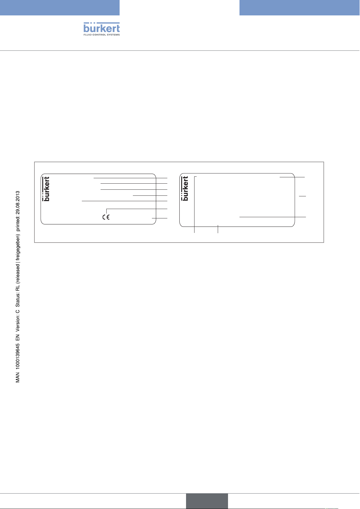
5.2. Description of the device name plate
8619 multiCELL
Supply: 12-36VDC
Temp: -10...+60 °C
IP65 PANEL (FRONT) IP20 (REAR)
Made in France
S-N:1110
00560204
W44ML
Figure 1 : Example of a name plate
1. Type of device
2. Electrical power supply
3. Ambient temperature range
4. Protection rating
5. Serial number
6. Conformity logo
7. Manufacturing code
8. Device fitted with a memory card reader
1
2
3
4
5
6
7
M0: 2xDI - 2xAO - 2xDO - SD CARD
M1: pH/ORP - PT100/1000
M2: RES COND 2/4 POLES PT100/1000
M3: 2xAO - 2xDO
Made in France
M4:
M5:
M6:
Softw.:
00560204 W44ML
12
11
8
9
}
10
9. Properties of the additional modules
10. Software options
11. Order code
12. Properties of the M0:MAIN board
6
english
Page 9
Type 8619
Technical data
6. TECHNICAL DATA
6.1. Conditions of use
Ambient temperature -10 to +70 °C (operating, without memory card), restricted to 0 ... +70°C if
a memory card is used
Air humidity < 85 %, non condensated
Height above sea level max. 2000 m
Protection rating • IP65 and NEMA4X (on front, once built in, housing closed)
• IP20 (non front parts inside the housing)
6.2. Compliance to standards and directives
The device conforms to the EC directives through the following standards:
• EMC: EN 61000-6-2, EN 61000-6-3
• Vibration: EN 60068-2-6
• Shock: EN 60068-2-27
UL recognised devices (
standards:
• UL 61010-1
• CAN/CSA-C22.2 n° 61010-1
) for the United States of America and Canada comply to the following
6.3. General technical data
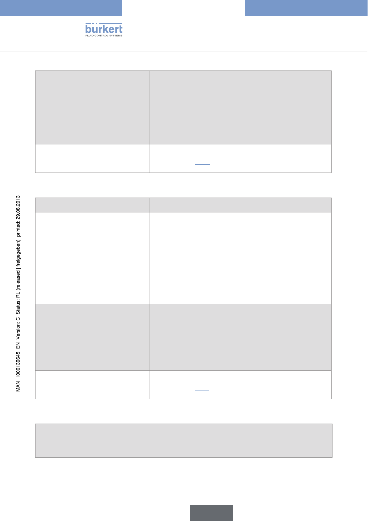
6.3.1. Mechanical data
Mechanical data Material
Built in and locking system / seal PPO / silicone
Front cover, upper layer, and keys / front
cover, sublayer, and display
Rear plate Stainless steel 304
Silicone / PC
Terminal blocks PBT, contacts in gold-plated copper alloy
Ground screw + spring washer Stainless steel 316 (A4)
english
7
Page 10
Type 8619
Technical data
PC
Stainless steel 304
Silicone
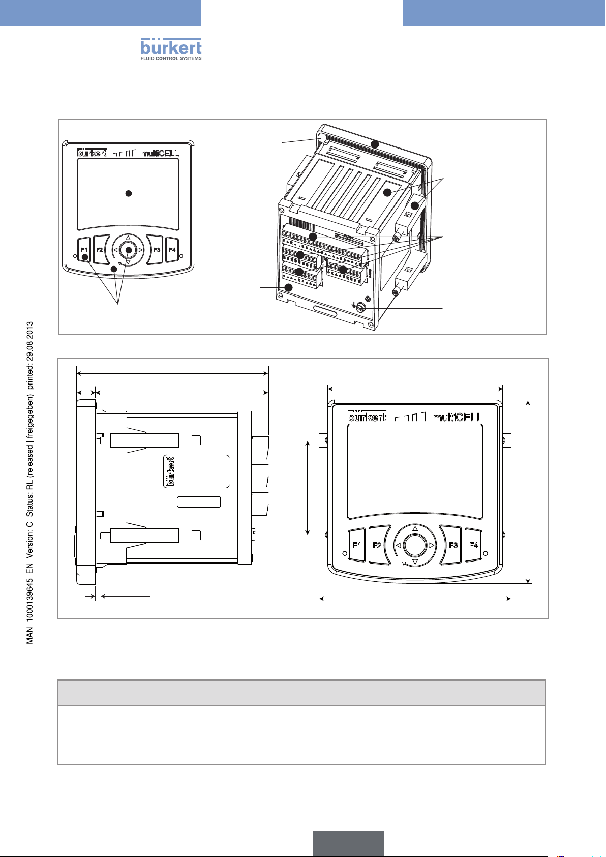
Figure 2 : Materials used for the multiCELL
112
10111
PC
Silicone
PPO
PBT, contacts in gold-plated
copper alloy
Stainless steel 316 (A4)
102
max. 4 mm
55
112
107
(wall thickness)
Figure 3 : Dimensions of the multiCELL [mm]
6.3.2. Specifications of the "M0:MAIN" board
Power supply 12-36 V DC, filtered and regulated
Specifications of the power source (not
provided) of UL-recognised devices, with
variable key PE72
8
• Limited power source (in accordance with chap. 9.3 of the UL
61010-1 standard)
• or class 2 type power source (according to the 1310/1585 and
60950-1 standards)
english
Page 11

Type 8619
Technical data
Max. power consumption (without additional
1.5VA
module, outputs not connected)
Power distribution ("PWR OUT") 12-36 V DC, 1.8A max.
All digital inputs ("DI") • Switching threshold V
• Switching threshold V
• Input impedance: 3kW
• Galvanically insulated
• Protected against polarity reversal and voltage spikes
• Frequency: 0.5 to 2500Hz
All analogue outputs ("AO") • 4-20mA current
• Any connection mode, in sink or source mode
• Galvanically insulated
• Protected against polarity reversal
• Max. loop impedance: 1100W at 36V DC, 610W at 24V DC,
100W at 12V DC
All digital outputs ("DO") • Transistor
• Connection mode unimportant in NPN or PNP mode
: 5 à 36 V DC
on
: < 2 V DC
off
• Galvanically insulated
• Protected against short circuits
• Max. voltage: 36V DC
• max. 700mA if one transistor is connected but max. 1A for both
transistors connected
• Max. frequency: 2000Hz
Electrical connection
• Per detachable 21-point set-screw connector, orange
• Refer to chap. 6.3.8 for the specifications of the connection
cables
Flow rate measurement (software option) Refer to the user manual for the flow sensor connected to the 8619
6.3.3. Specifications of the input board "Input"
Power consumption 0.1 VA
Digital inputs ("DI") • Switching threshold V
• Switching threshold V
• Input impedance: 3 kW
• Galvanically insulated
: 5 à 36 V DC
on
: < 2 V DC
off
• Protected against polarity reversal and voltage spikes
• Frequency: 0.5 to 2500 Hz
english
9
Page 12
Type 8619
Technical data
Analogue inputs ("AI") • Any connection mode, in sink or source mode
• Galvanically insulated
• Accuracy: ±0,25%
• Current input: 0 - 22 mA or 3,5 - 22 mA. Max. voltage: 36 V DC.
Impedance: 50 W. Resolution : 1.5 µA
• Voltage input: 0 - 5 V DC or 0 - 10 V DC. Max. voltage: 36 V DC.
Impedance: 110 kW. Resolution: 1 mV
Electrical connection
• Per detachable 9-point set-screw connector, orange
• Refer to chap. 6.3.8 for the specifications of the connection
cables
6.3.4. Specifications of the additional outputs board "OUT"
Power consumption 0.1VA
All digital outputs ("DOx") • Transistor
• Any connection mode, in NPN or PNP mode
• Galvanically insulated
• Protected against short circuits
• Max. voltage: 36V DC
• max. 700mA per transistor but max. 1A if both transistors are
connected
• Max. frequency 2000Hz
All analogue outputs ("AOx") • 4-20mA current
• Any connection mode, in sink or source mode
• Galvanically insulated
• Protected against polarity reversal
• Max. loop impedance: 1100W at 36V DC, 610W at 24V DC,
100W at 12V DC
Electrical connection
• Per detachable 9-point set-screw connector, black
• Refer to chap. 6.3.8 for the specifications of the connection
cables
10
6.3.5. Specifications of the memory card reader/recorder
• Memory card type
• Capacity
• File system
• SD (Secure Digital)
• 2 Go max.
• FAT16
english
Page 13

Type 8619
Technical data
6.3.6. Specifications of the "pH/redox" module
pH measurement
• pH measurement range
• Resolution of pH measurement
• Accuracy of pH measurement
• Potential difference measurement range
• Resolution of potential difference
measurement
• Accuracy of potential difference
measurement
• pH probe type
Power consumption 0.1VA
Measurement of the oxidation reduction
potential
• Oxidation reduction potential measurement
range
• Resolution of the potential difference
measurement
• Accuracy of potential difference
measurement
• -2.00...+16.00
• 0.01pH
• 0.02pH
• -600...+600mV
• 0.1mV
• 1mV
• Electrochemical
• -2000 ... +2000mV
• 0.1mV
• 1mV
• Electrochemical
• Oxidation reduction potential probe type
Temperature measurement
• Measurement range
• Measurement resolution
• Measurement accuracy
• Temperature sensor type
Electrical connection
• -25°C ... +130°C
• 0.1°C
• 1°C
• Pt100 or Pt1000, with 2 or 3 wires
• Per detachable 9-point set-screw connector, grey
• Refer to chap. 6.3.8 for the specifications of connection
cables
6.3.7. Specifications of the "COND" conductivity module
Resistance measurement (without conductivity
sensor connected)
Power consumption 0.25VA
Conductivity cell type With 2 or 4 electrodes; the specifications of Bürkert cells are
5W ... 1MW
described in the related operating instructions.
english
11
Page 14

Type 8619
Technical data
Conductivity measurement (with
connected conductivity sensor)
• Measurement range
• Measurement resolution
• Measurement error
Resistivity measurement (with connected
conductivity sensor)
• Measurement range
• Measurement resolution
• Measurement error (without sensor)
Temperature measurement
• Measurement range
• Measurement resolution
• Measurement error
• Temperature sensor type
Electrical connection
• 0.000 µS/cm...2 S/cm (depends on the conductivity sensor)
-9
• 10
S/cm
• < 0.5% of measured value + sensor error
• 0.500W.cm...100MW.cm (depends on the conductivity sensor)
-1
• 10
W.cm
• < 0.5% of measured value
• -40°C ... 200°C
• 0.1°C
• ±1°C
• Pt100 or Pt1000, with 2 or 3 wires
• Per detachable 9-point set-screw connector, green
• Refer to chap. 6.3.8 for the specifications of the connection
cables
6.3.8. Specifications of the connection cables
• Use shielded cables for the electrical connection.
• Be sure to use cables in which the wires present the specifications described in the table below.
Wire specifications Dimensions of the max. clamping area
• Single core H05(07) V-U 0.2...1.5 mm
• Flexible wire H05(07) V-K 0.2...1.5 mm
• With non-insulated end connection 0.2...1.5 mm
• With insulated end connection 0.2...0.75 mm
Table 1: Specifications of the wires making up the connection cables
2
2
2
2
12
english
Page 15

Type 8619
Installation and wiring
7. INSTALLATION AND WIRING
7.1. Safety instructions
DANGER
Risk of injury due to electrical discharge.
• Shut down and isolate the electrical power source before carrying out work on the system.
• Observe all applicable accident protection and safety regulations for electrical equipment.
WARNING
Risk of injury due to non-conforming installation.
• Electrical installation can only be carried out by qualified and authorised personnel with the appropriate tools.
• Install appropriate safety devices (correctly rated fuse and/or circuit-breaker).
• The use of probes/sensors sold by Bürkert is preferable.
• Follow the instructions on installation and wiring of remote sensors connected to the multiCELL.
Risk of injury due to unintentional switch on of power supply or uncontrolled restarting of the
installation.
• Take appropriate measures to avoid unintentional activation of the installation.
• Guarantee a set or controlled restart of the process subsequent to the installation of the device.
Protect this device against electromagnetic interference, ultraviolet rays and, when installed outdoors, the effects of the climatic conditions.
7.2. Building the device into a housing or cabinet
→ Follow the instructions below to build the multiCELL delivered fully assembled, into a housing or cabinet.
92 +0,5/-0
5
5,55,5
92 +0,5/-0
10
Stage 1:
→ Check that the thickness of the door of the
housing or cabinet is 4 mm max.
→ Cut out the hole in the door of the electrical housing
or cabinet in accordance with the standard, IEC
61554:1999 (DIN 43700), allowing the space
required around the cut-out and inside the cabinet
to easily handle the 4 locking systems, delivered
with the multiCELL.
This diagram is not to scale. The dimensions are given in
mm.
english
13
Page 16

Type 8619
Installation and wiring
Screw
Body
x4
Stage 2:
Prepare the 4 locking systems:
→ Insert a screw into each device.
→ Tighten the screw until the end of the shaft of the
screw is flush with the device.
Stage 3:
→ Slide the housing into the cut-out with the con-
nectors to the back until it can go no further.
Stage 4:
→ Insert (1) the hooks on the first locking system
into the slots on the housing.
1
2
→ Pull the locking system (2) until you hear a click.
The click may be heared when tightening the
locking system at stage 6.
Stage 5:
→ Place the locking system flush against the mul-
tiCELL by hand, so that the hooks remain in place.
14
english
Page 17

Type 8619
Installation and wiring
Stage 6:
→ Fully tighten the screws using an appropriate
screwdriver.
→ Repeat stages 4 to 6 to fit the other 3 locking
systems.
Figure 4 : Insertion of the 8619 into a housing or cabinet
7.3. Electrical wiring
DANGER
Risk of injury due to electrical discharge.
• Shut down and isolate the electrical power source before carrying out work on the system.
• Observe all applicable accident protection and safety regulations for electrical equipment.
• Use a high quality electrical power supply (filtered and regulated).
• Connect the functional earth on the installation to the ground screw on the device.
• Connect the shielding on each wire to an "FE" (functional earth) terminal to guarantee the equipotentiality of the installation.
• Use shielded cables that respect the specifications described in "Table 1: Specifications of the wires
making up the connection cables".
7.3.1. Electrical connections
For all versions of the multiCELL, the electrical connection is made by set-screw connectors.
7.3.2. Wiring the M0:MAIN board
The M0:MAIN board is used to connect the multiCELL's electrical power source. It has:
• 2 digital inputs (marked DI1 and DI2), for connecting a flow sensor for example
• Two 4-20 mA analogue outputs (marked AO1 and AO2)
• 2 digital outputs (marked DO1 and DO2)
The inputs and outputs are galvanically insulated and therefore voltage free.
english
15
Page 18

Type 8619
Installation and wiring
1st digital output at
external instrument
5-36 VDC
12-36 VDC
-
+
Power supply
2nd digital
output at external
instrument
-
+
5-36 VDC
0 VDC
1st 4-20 mA input at
external instrument
+-
0 VDC
12-36 VDC
0 VDC
2nd 4-20 mA input at
12-36 VDC
0 VDC
external instrument
+-
Load 1
+
-
0 VDC
12-36 VDC
12-36 VDC
+
-
0 VDC
Load 2
SUPPLY PWR OUT DI1 FEDI2 DO2DO1AO1 AO2 FE FE
Electrical
power supply
V-
V+
Power
distribution
FE
-
+
FE
D+D-D+
Digital inputs Digital
D-
I+I-I+
FE
Analogue
outputs
I-
FE
T+T-T+
outputs
T-
FE
DI1, DI2, AO1, AO2, DO1 and DO2: designation in the configuration menus of the M0 main board.
FE = functional earth
Figure 5 : Wiring of the "M0:MAIN" board
16
english
Page 19

Type 8619
Installation and wiring
PNP
1
1
V+
NPN
V+
12-36 VDC
3
-
0V
2
+
Power supply
-
+
V-
FE
V+
SUPPLY PWR OUT DI1 FEDI2 DO2DO1AO1 AO2 FE FE
FE
D+D-D+
D-
FE
I+I-I+
FE = functional earth
Figure 6 : Connection example for the 8619 with two flow sensors, type 8030
8071
X
I-
3
FE
T+T-T+
0V
2
T-
FE
8041
4...20V+V-PEPls+Pls-
VDC
red
black
white
12-36 VDC
-
+
Power supply
-
+
V-
FE
V+
SUPPLY PWR OUT DI1 FEDI2 DO2DO1AO1 AO2 FE FE
FE
D+D-D+
D-
FE
I+I-I+
I-
FE
T+T-T+
FE = functional earth
Figure 7 : Connection example for the 8619 with 2 flow sensors, types 8071 and 8041
1 2 3 4 5 6
T-
FE
17
english
Page 20

7.3.3. Wiring the input module "INPUT"
The "INPUT" inputs module has:
• Two analogue inputs;
• Two digital inputs.
The inputs are galvanically insulated, and therefore voltage free.
1st 0/4-20 mA output (at
+-
external instrument)
0 VDC
2nd 0/4-20 mA output (at external instrument)
Type 8619
Installation and wiring
+-
12-36 VDC
12-36 VDC
A+A-A+
1
2 3 4 5 6 7 8 9
(AI1) (AI2) (DI1) (DI2)
0 VDC
A-
FE
5-36 VDC
0 VDC
D+D-D+
5-36 VDC
1st digital output (at
external instrument)
+
-
0 VDC
D-
2nd digital output (at
external instrument)
(designation in the configuration menus of the Mx
input module)
18
analogue
digital inputs
inputs
FE = functional earth
Figure 8 : Connecting the analogue inputs to a 2-wire current transmitter and connecting the digital inputs of the input
module
english
Page 21

Type 8619
Installation and wiring
1st 0/4-20 mA output
(at external instrument)
12-36 VDC
0 VDC
+-
I
12-36 VDC
A+A-A+
1
2 3 4 5 6 7 8 9
A-
FE
(AI1) (AI2) (DI1) (DI2)
digital inputsanalogue
inputs
+-
0 VDC
12-36 VDC
D+D-D+
2nd 0/4-20 mA output
(at external instrument)
I
1st digital output (at
external instrument)
0 VDC
+
-
12-36 VDC
+
-
2nd digital output (at
external instrument)
0 VDC
D-
(designation in the configuration menus of the Mx
input module)
FE = functional earth
Figure 9 : Connecting the AI1 analogue input in source mode and the analogue input AI2 in sinking mode to a 3-wire
current transmitter (for example type 8025 with relay outputs) and connecting the digital inputs of the input
module
1st 0-5/10 V DC output
(at external instrument)
+-
V
0 VDC
+
-
1st digital output (at
external instrument)
12-36 VDC
12-36 VDC
0 VDC
12-36 VDC
+
-
2nd digital output (at
external instrument)
0 VDC
A+A-A+
1
2 3 4 5 6 7 8 9
A-
FE
D+D-D+
(AI1) (AI2) (DI1) (DI2)
D-
(designation in the configuration menus of the Mx
input module)
digital inputsanalogue
inputs
FE = functional earth
Figure 10 : Connecting the analogue inputs to a voltage transmitter and connecting the digital inputs of the input module
english
19
Page 22

Type 8619
Installation and wiring
7.3.4. Wiring the output module "OUT"
The "OUT" outputs module has two 4-20 mA analogue outputs and two digital outputs. The outputs are galvanically insulated, and therefore voltage free.
1st 4-20 mA
input (at external
instrument)
+-
0 VDC
12-36 VDC
I+I-I+
1
2 3 4 5 6 7 8 9
(AO1) (AO2) (DO1) (DO2)
FE = functional earth
Figure 11 : Wiring the "OUT" output module
12-36 VDC
12-36 VDC
0 VDC
I-
FE
T+T-T+
2nd 4-20 mA input (at
+-
external instrument)
Load 1
+
0 VDC
12-36 VDC
0 VDC
-
+
-
Load 2
T-
(designation in the configuration menus of the Mx
additional output module)
digital outputsanalogue outputs
7.3.5. Wiring the "pH/ORP" module
• Wire a pH/redox sensor in symmetrical mode to obviate the influence of interference and, in this case,
wire the equipotential electrode (compulsory).
• When the pH/redox sensor is wired in asymmetrical mode, measurement of the pH or the oxidation
reduction potential may drift over time when the equipotential electrode is not wired.
20
english
Page 23

Type 8619
Installation and wiring
black
Equipotential electrode
(1)
Temperature
(2)
(2)
white
black
sensor
Reference
electrode
pH measurement
(1)
translucid
(2)
blue
(2)
brown
electrode
FE
TS
RE
RE
ME
1 2 3 4 5 6 7 8 9
GD
CG
SE
TS
FE = functional earth
(1)
Colour of the wires in the Bürkert connection cables with order codes 561904, 561905 or 561906.
(2)
Colour of the wires in the Pt1000 sensor with order code 427023 and its Bürkert connection cable with order code
427113.
Figure 12 : Wiring a Bürkert 8200 type sensor and a Pt1000 temperature sensor in symmetrical mode
(1)
black
Reference
(1)
Temperature
sensor
electrode
translucid
pH measurement electrode
(recommended)
Equipotential electrode
Strap (not delivered)
FE
TS
RE
RE
ME
1 2 3 4 5 6 7 8 9
GD
CG
SE
TS
FE = functional earth
(1)
Colour of the wires in Bürkert connection cables with order codes 561904, 561905 or 561906.
Figure 13 : Wiring a pH sensor and a Pt100 or Pt1000 temperature sensor in asymmetrical mode to a pH/ORP module
english
21
Page 24

Type 8619
Installation and wiring
Temperature
Oxidation reduction potential
sensor
measurement electrode
Reference electrode
Strap (not delivered)
FE
TS
RE
RE
ME
1 2 3 4 5 6 7 8 9
GD
CG
SE
TS
FE = functional earth
Figure 14 : Wiring an oxidation reduction potential sensor and a Pt100 or Pt1000 temperature sensor in a pH/ORP
module
Oxidation reduction potential
measurement electrode
Temperature
sensor
Reference
electrode
pH
measurement
electrode
FE
TS
RE
RE
ME
1 2 3 4 5 6 7 8 9
GD
CG
SE
TS
FE = functional earth
Figure 15 : Wiring a pH sensor, an oxidation reduction potential sensor and a Pt100 or Pt1000 temperature sensor in a
pH/ORP module
7.3.6. Wiring the "COND" conductivity module
Conductivity
sensor
Temperature
sensor
22
P-
C-
FE
TS
TS
P+
C+
1 2 3 4 5 6 7 8 9
GD
SE
FE = functional earth
Figure 16 : Wiring a resistive conductivity cell with 2 electrodes and a Pt100 or Pt1000 temperature sensor in a conduc-
tivity module
english
Page 25

Type 8619
Installation and wiring
Temperature
sensor
P-
C-
FE
TS
TS
P+
C+
1 2 3 4 5 6 7 8 9
Figure 17 : Wiring a resistive conductivity cell with 4 electrodes and a Pt100 or Pt1000 temperature sensor in a conduc-
tivity module
GD
SE
FE = functional earth
english
23
Page 26

Type 8619
Adjustment and commissioning
8. ADJUSTMENT AND COMMISSIONING
8.1. Safety instructions
WARNING
Risk of injury due to non-conforming adjustment.
Non conforming adjustment could lead to injuries and damage the device and its environment.
• The operators in charge of adjustment must have read and understood the contents of this manual.
• In particular, observe the safety recommendations and intended use.
• The device/installation must only be adjusted by suitably trained staff.
WARNING
Danger due to non-conforming commissioning.
Non-conforming commissioning could lead to injuries and damage the device and its surroundings.
• Before commissioning, make sure that the staff in charge have read and fully understood the contents of the
manual.
• In particular, observe the safety recommendations and intended use.
• The device/installation must only be commissioned by suitably trained staff.
Before commissioning, calibrate each measuring sensor connected to the device.
8.2. Switching on the device for the first time
When switching on the device for the first time, the display shows the first view in Process level:
M0:MAIN
MENU
OFF
OFF
DI1
DI2
2010/06/29
OFF
OFF
6.000
20.00
13:40
DO1
DO2
mA
AO1
mA
AO2
24
Figure 18 : Display when switching on for the first time
When switched on subsequently, the last active view in the Process leve is displayed. See chap. 8.7 to
browse in all views in Process level.
english
Page 27

H
T
Type 8619
Adjustment and commissioning
8.3. Description of the icons
Figure 19 : Position of the icons
Icon Meaning and alternatives
Default icon when process monitoring is not activated via the "Diagnostics" menu; if monitoring is
activated, this icon indicates that the parameters monitored are not out of range.
If at least one monitoring is activated, the alternative icons in this position are:
•
, combined with : go to the menu "Information -> System log" to read the associated warning
message.
, combined with X: go to the menu "Information -> System log" to read the associated error
•
message.
Device currently measuring.
M0:MAIN
X
MENU
OFF
OFF
DI1
DI2
2010/06/29
OFF
OFF
6.000
20.00
13:40
DO1
DO2
mA
AO1
mA
AO2
The alternative icons in this position are:
flashing: HOLD mode activated.
•
•
flashing: running check that an output is working and behaving correctly.
X
"Maintenance" event; Go to the menu "Information -> System log" to read the associated message.
"Warning" event; Go to the menu "Information -> System log" to read the associated message.
Error" event; Go to the menu "Information -> System log" to read the associated message.
Memory card inserted and datalogger activated.
X
The alternative to this position is the icon
System log", to read the associated error message.
indicating an error. Go to the menu "Information ->
25
english
Page 28

Type 8619
Adjustment and commissioning
8.4. Using the navigation button and the dynamic keys
The arrows displayed show
the directions in which you
can browse in this view.
26
To activate the dynamic
function to the far left,
press F1
LED A: shows the system
status. See chap. 9.
To activate the second
dynamic function, press F2
MENU ABORT SAVE OK
F1
F2
F3
F4
To activate the third
dynamic function, press F3
To activate the dynamic
function to the far right, press
F4
LED B: shows the sensor
status. See chap. 9.
The navigation button is used to move in 4 directions, symbolised throughout the
manual by
Figure 20 : Using the navigation button and the dynamic keys
and .
You want to... Press...
....access the Configuration level Dynamic function, "MENU", from any view in Process
level
...go back to Process level Dynamic function, "MEAS"
...access the menu displayed Dynamic function, "OK"
...access the highlighted function Dynamic function, "OK"
...confirm the enter Dynamic function, "OK"
...save modifications Dynamic function "SAVE"
...go back to the parent menu Dynamic function "BACK"
...cancel the current operation Dynamic function "ABORT"
...set a setpoint value Dynamic function "SETP"
...activate manual mode in a configured and activated
Dynamic function "MANU"
function
...manually set the percentage of the function Dynamic function "CMD"
...force the result of a function to 0% Dynamic function "0%"
...force the result of a function to 100% Dynamic function "100%"
...activate automatic mode in a configured and acti-
Dynamic function "AUTO"
vated function
...start teach-in Dynamic function "START"
...end teach-in Dynamic function "END"
...answer the question asked in the affirmative Dynamic function "YES"
...answer the question asked in the negative Dynamic function "NO"
...select the highlighted character or mode Dynamic function "SEL"
english
Page 29

Type 8619
Adjustment and commissioning
You want to... Press...
...browse in Process level
...browse in the Configuration level menus
next view
previous
view
next level
previous
level
...browse in the menu functions
...set the contrast or brightness percentage for the
display (after accessing the function in the "Parameters" menu)
...modify a numerical value or the units
...allocate the "+" or "-" sign to a numerical value
display the next
menu
highlight the next
function
increase the
percentage
increment the
figure selected or modify
the units
select the next
figure
to the extreme left of the numerical value then
display the pre-
vious menu
highlight the pre-
vious function
reduce the
percentage
decrement the
figure selected or modify
the units
select the pre-
vious figure
until the desired sign is displayed
...move the decimal point in a numerical value
to the extreme right of the numerical value
then
place
until the decimal point is in the desired
8.5. Entering some text
This chap. describes how to use the keyboard displayed to modify the name of a process variable (13 characters
max.), a function (12 characters max.) or the title of a view (12 characters max.).
english
27
Page 30

Type 8619
Adjustment and commissioning
Cursor of the data entering area
Selector
The arrows indicate that the selector
can be moved on the line or that the
3 available character pages can be
scrolled through.
Indicates the active page
among 3 pages
Edit name
ABORT SEL
_
f
_
a b c d e f g 7 8 9
h i j k l m n 4 5 6
o p q r s t u 1 2 3
v w x y z + - . 0
' ? ! : ; % * / < >
2/3
F3
SAVE
F4
→ To move the cursor in the data entering area using keys and , first move the selector into
the data entering area using the keys
→ To insert a character in place of the cursor, move the selector over this character and press key
and .
F3
(function "SEL").
→ To remove the character before the cursor, move the selector into the data entering area then press key
(function "backspace"):
F3
selector
Edit name
ABORT
_
f
_
a b c d e f g 7 8 9
h i j k l m n 4 5 6
o p q r s t u 1 2 3
v w x y z + - . 0
' ? ! : ; % * / < >
2/3
F3
The arrows indicate that the selector can be
moved on the name entering area.
SAVE
F4
To retrieve the original name of a variable, even after modification and saving:
→ move the selector into the customized name entering area.
28
→ delete all the characters.
→ save.
8.6. Operating levels
The device has 2 operating levels: the Process level and the Configuration level which is made of the following
5 menus : "Parameters", "Calibration", "Diagnostics", "Tests" and "Information".
english
Page 31

Type 8619
Adjustment and commissioning
8.7. Process level
M0:MAIN:
OFF
OFF
MENU
U1:PH_COND
2
2
3
3
M0:MAIN:
2010/06/29
DI1
DI2
6.000
20.00
2010/06/29
25
6.53
M6:Outputs
OFF
OFF
13:40
DO1
DO2
mA
AO1
mA
AO2
M1:pH
2010/06/29
0.500
30.00
1.000
33.00
M2:Conductivity
13:40
L/s
DI1
L
DI1
L/s
DI2
L
DI2
6.53
39.20
25.2
2010/06/29
13:40
25
pH
mV
25.2
°C
13:40
mS/cm
........
°C
MENU
Views of the modules connected to the device (cannot be modified):
• "M0:MAIN" view: displays the values of inputs and outputs on the main
board; the second "M0:" view is available if the software option, "FLOW", is
activated.
• "M1:" to "M6:" views display the data for modules 1 to 6.
13:40
mS/cm
pH
U4:PROCESS1
......
MENU
2010/06/29
1
3
0
1
6.53
25
25.2
205
13:40
pH
mS/cm
°C
l/min
User defined views (U1 to U4) are
each used to display 1, 2 or 4 data
or a graph. Only the effectively
defined views are shown.
2010/06/29
OFF
OFF
5.000
12.00
13:40
DO1
DO2
mA
AO1
mA
AO2
MENU
F1:A+B
MENU
µS/cm
PV
µS/cm
SP
%
CMD1
F3 Dos.St
13:40
F6:ONOFF
1
1
F2:PROP
1
PV
2010/06/29
250.2
0
CMD1
2010/06/29
0
0
0
148
57
205
MENU
13:40
13.00
L/min
L/min
l/min
FlowProcess1
13:40
........
µS/cm
%
MANU
0
0
SETPMENU
2010/06/29
250.0
500.0
0.00
Off
Views of active functions which
cannot be modified (F1: to F6:)
are used to display one function
each. Only the views of functions
declared "active" are shown.
29
english
Page 32

8.8. Configuration level access
On any view in
Process level,
press
MENU
F1
MEAS
This is
when the
device is being parame-
tered............
....................
Parameters
OK
F4
Code
incorrect
"Param-
eters" code
correct
1)
Type 8619
Adjustment and commissioning
This is
when the
device is being parame-
tered............
Parameters
....................
System
Display
Functions
Datalogger
M0:Outputs
Mx:pH/ORP
Mx:Conductivity
Mx:Outputs
Mx:Inputs
2)
MEAS
MEAS
Calibration
Diagnostics
Tests
OK
OK
F4
F4
Code
incorrect
Code
incorrect
Code
incorrect
"Cali-
bration" code
correct
1)
"Diag-
nostics"
code correct
1)
"Tests"
code
correct
1)
Calibration
System
M0:Outputs
M0:Inputs
Mx:pH/ORP
Mx:Conductivity
Mx:Outputs
Mx:Inputs
Diagnostics
System
Mx:pH/ORP
Mx:Conductivity
Mx:Inputs
Tests
System
Simulate PV
T
M0:Outputs
Mx:Outputs
30
MEAS
OK
F4
Information
MEAS
1)
The code is not requested if the default code "0000" is used.
2)
This menu is available as an option.
OK
F4
Information
Error
Warning
Maintenance
Smiley
System log
Versions
english
Page 33

Type 8619
Adjustment and commissioning
8.9. Calibrating the measuring sensors
8.9.1. Calibrating a flow sensor
Enter the K factor in pulse/liter unique to the fitting used. Refer to the user manual of the fitting used.
→
Calibration
Mx:Inputs
DI1/2:FlowM0:Inputs
K factor ENTERING
8.9.2. Calibrating a conductivity sensor
Choose the reference solution used in the menu "Parameters -> Mx:Conductivity -> Buffer".
→
→ Calibrate the conductivity sensor by automatically determining its specific C constant.
Calibration
Automatic calibMx:Conductivity
RESULT
8.9.3. Calibrating a pH sensor
• In order not to interrupt the process, activate the HOLD function in the menu "Calibration -> System ->
Hold". The Hold mode is automatically deactivated when the multiCELL restarts after a power interruption,
if the Hold mode was activated at the moment of the power cut-off.
• Before each calibration, correctly clean the electrode with a suitable product.
→ Choose the buffer solution used, in the menu "Parameters -> Mx:pH/ORP -> Buffer". The multiCELL auto-
matically recognizes the pH of the buffer used.
→ Automatically calibrate the pH sensor:
Calibration
Mx:pH/ORP
The calibration may fail:
• a possible "warning" message indicates either an error in the buffer solution or the ageing of the probe.
• a possible "error" message indicates that the probe must be replaced.
pH auto calib.
NON
1st point
2nd point?
YES
Rinse
2nd point
pH Cal.Result
31
english
Page 34

Type 8619
Adjustment and commissioning
8.9.4. Calibrating a redox sensor
• Modify the default calibration limits before calibrating your sensor in the menu "Parameters" -> "Mx:pH/
ORP" -> "Calibration limits" -> "Offset ORP".
• In order not to interrupt the process, activate the HOLD function in the menu "Calibration -> System ->
Hold". The Hold mode is automatically deactivated when the multiCELL restarts after a power interruption,
if the Hold mode was activated at the moment of the power cut-off.
• Before each calibration, correctly clean the electrode with a suitable product.
→ Calibrate the redox sensor using a 1-point procedure.
The calibration may fail:
• a possible "warning" message indicates either an error in the buffer solution or the ageing of the probe.
• a possible "error" message indicates that the probe must be replaced.
The 1-point calibration procedure is used for a quick calibration by adjusting the zero of the measurement graph
with a buffer solution with a known oxidation reduction potential.
Calibration ORP calibrationMx:pH/ORP 1st point
→ Immerse the clean probe in the redox solution:
the multiCELL displays the measured potential
difference of the solution
1st point
465.0 mV
475.0 mV
→ Enter the potential difference of the redox
solution (indicated on the bottle).
OK
F4
ORP Calibr. result
Offset:-55.60 mV
The multiCELL displays the calibration result.
1)
32
english
Page 35

Type 8619
Adjustment and commissioning
8.10. Process inputs or values
8.10.1. On the M0:MAIN board
M0:MAIN
1)
Available on the device if the software option
None
Warning
AO1
AO2
DO1
DO2
SysSwitch
DI1
DI2
DI1: Qv
DI2: Qv
DI1: TotA
DI1: TotB
DI2: TotA
DI2: TotB
DI1: Hz
DI2: Hz
Fx:
1)
"FLOW" is active
8.10.2. On the input module
Mx:Entrées
1)
Available on the device if the software option
"FLOW" is active
AI1
AI2
DI1
DI2
DI1: Qv
DI2: Qv
DI1: TotA
DI1: TotB
DI2: TotA
DI2: TotB
AI1Raw
AI2Raw
DI1:Hz
DI2:Hz
1)
"Warning" = event generated by the multiCELL
"AOx" = analogue output
"DOx" = digital output
"System switch" = when the corresponding event is
configured and activated
"DIx" = digital input
"DIx Qv" = flow rate on digital input DIx
"DIx TotA" = totalizer A on digital input DIx
"DIx TotB" = totalizer B on digital input DIx
"DIx Hz" = frequency on digital input DIx
"Fx:" = result of configured and activated functions
"AIx" = scaled process variable.
"DIx" = digital input
"DIx Qv" = flow rate on digital input DIx
"DIx TotA" = totalizer A on digital input DIx
"DIx TotB" = totalizer B on digital input DIx
"AIxRaw" = current or voltage standard signal on analogue input AIx
"DIx Hz" = frequency on digital input DIx
8.10.3. On the additional outputs module
Mx:Outputs
AO1
AO2
DO1
DO2
"AOx" = analogue output
"DOx" = digital output
english
33
Page 36

8.10.4. On the pH/redox module
Type 8619
Adjustment and commissioning
Mx:pH/ORP
pH
mV
ORP
°C
°F
RTD
"pH" = measured pH of the fluid
"mV" = measured pH of the fluid in mV
"ORP" = measured oxidation reduction potential of the fluid in mV
"°C" = measured temperature of the fluid in °C
"°F" = measured temperature of the fluid in °F
"RTD" = resistance of the temperature input in W
8.10.5. On the conductivity module
Mx:Conductivity
µS/cm
W.cm
°C
°F
RTD
TDS
%
USP
"µS/cm" = measured conductivity of the fluid
W.cm" = resistivity
"
"°C" = measured temperature of the fluid in °C
"°F" = measured temperature of the fluid in °F
"RTD" = input resistance of the temperature stage in W
"TDS" = quantity of dissolved solids in the fluid in ppm
"%" = mass concentration of the fluid (software option)
"USP" = state of the USP function
34
english
Page 37

Type 8619
Maintenance and troubleshooting
9. MAINTENANCE AND TROUBLESHOOTING
9.1. Safety instructions
DANGER
Risk of injury due to electrical discharge.
• Shut down and isolate the electrical power source before carrying out work on the system.
• Observe all applicable accident protection and safety regulations for electrical equipment.
WARNING
Risk of injury due to non-conforming maintenance.
• Maintenance must only be carried out by qualified and skilled staff with the appropriate tools.
• Guarantee a set or controlled restarting of the process, after a power supply interruption.
9.2. Maintenance of the multiCELL
The multiCELL can be cleaned with a duster slightly moistened with water with possible addition of a detergent
compatible with the materials it is made of.
Please feel free to contact your Bürkert supplier for any additional information.
9.3. If you encounter problems
The following table gives the association between the LEDs, the icons and the types of events generated by the
device.
The messages generated in the system log are detailled in the complete instruction manual.
LEDs Displayed icons
left right Smiley Error Warning Maintenance
green green
green red
red green
green orange
orange green
red green
any colour any colour any colour
X
X
Type of event and possible
cause
Normal operating and default
icon if no diagnostic function is
active on the device.
"Error" event linked to the
diagnostic.
"Error" event linked to the
device.
"Warning" event linked to the
diagnostic.
"Warning" event linked to the
device.
"Maintenance" event linked to
the calibration.
Problem linked to the
X
datalogger
english
35
Page 38

Type 8619
Spare parts and accessories
10. SPARE PARTS AND ACCESSORIES
CAUTION
Risk of injury and/or material damage caused by the use of unsuitable parts.
Incorrect accessories and unsuitable replacement parts may cause injuries and damage the device and the surrounding area.
• Use only original accessories and original replacement parts from Bürkert.
11. PACKAGING, TRANSPORT
ATTENTION
Damage due to transport
Transport may damage an insufficiently protected device.
• Transport the device in shock-resistant packaging and away from humidity and dirt.
• Do not expose the device to temperatures that may exceed the admissible storage temperature range.
12. STORAGE
CAUTION
Poor storage can damage the device.
• Store the device in a dry place away from dust.
• Storage temperature: -20 ... +70°C, restricted to 0 ... +70°C if a memory card is inserted
13. DISPOSAL OF THE DEVICE
→ Dispose of the device and its packaging in an environmentally-friendly way.
CAUTION
Damage to the environment caused by products contaminated by fluids.
• Keep to the existing provisions on the subject of waste disposal and environmental protection.
Note
36
Comply with the national and/or local regulations which concern the area of waste disposal.
english
Page 39

Page 40

www.burkert.com
 Loading...