

Page 1
Operating Instructions
Bedienungsanleitung
Instructions de Service
Types 8626 / 8710 / 8711 / 8712 / 8713 / 8716
Mass Flow Controller (MFC)
Types 8006 / 8700 / 8701 / 8702 / 8703 / 8706
Mass Flow Meter (MFM)
Page 2

We reserve the right to make technical changes without notice.
Technische Änderungen vorbehalten.
Sous resérve de modification techniques.
© 2002 Bürkert Werke GmbH & Co. KG
Operating Instructions 0070
2/10_EU-ml_00804577
Page 3

MassFlowController (MFC)
Types 8626 / 8710 / 8711 / 8712 / 8713 / 8716
MassFlowMeter (MFM)
Types 8006 / 8700 / 8701 / 8702 / 8703 / 8706
GENERAL NOTES ...................................................................................................................................... 5
Symbols......................................................................................................................................................... 5
Safety notes ................................................................................................................................................ 5
Protection from damage by electrostatic charging................................................................ 6
Scope of delivery...................................................................................................................................... 6
Warranty conditions ................................................................................................................................ 6
SYSTEM DESCRIPTION ......................................................................................................................... 7
Type systematics..................................................................................................................................... 7
General function ....................................................................................................................................... 8
Sensors ......................................................................................................................................................... 9
Thermal measurement principle ................................................................................................. 9
Inline sensor (Types 8626 / 8006 / 8716 / 8706) ............................................................10
Bypass sensor in conventional technology "capillary"
(Types 8710 / 8700) ...................................................................................................................... 11
Bypass sensor in CMOSens® technology
(Types 8713 / 8703 / 8712 / 8702 / 8711 / 8701) ............................................................ 12
english
Control electronics ................................................................................................................................ 13
Proportional valve .................................................................................................................................. 14
TECHNICAL DATA ................................................................................................................................... 17
Type 8626 / 8006 MASS FLOW INLINE ................................................................................... 18
Type 8710 / 8700 MASS FLOW CMOSens® ........................................................................ 19
Type 8711 / 8701 MASS FLOW CMOSens® ........................................................................ 20
Type 8712 / 8702 MASS FLOW CMOSens® ........................................................................ 21
Type 8713 / 8703 MASS FLOW CMOSens® ........................................................................ 22
Type 8716 / 8706 MASS FLOW INLINE ................................................................................... 23
MFC/MFM - 3
Page 4

ASSEMBLY, INSTALLATION AND COMMISSIONING ...................................................... 24
Dimensional drawings.......................................................................................................................... 24
General notes on installation and operation ............................................................................ 28
Mechanical and fluidic installation ................................................................................................. 29
Electrical connections.......................................................................................................................... 30
english
Inputs / outputs ........................................................................................................................................ 37
Operation with additional isolation valve ............................................................................... 29
Fluidic connections .......................................................................................................................... 29
Assembly of clamping ring screw joints ............................................................................... 30
Connection configuration Type 8626 / 8006 ....................................................................... 31
Connection configuration Type 8710 / 8700 ..................................................................... 32
Connection configuration Type 8711 / 8701 ....................................................................... 33
Connection configuration Type 8712 / 8702 ....................................................................... 34
Connection configuration Type 8713 / 8703 ....................................................................... 35
Connection configuration Type 8716 / 8706 ....................................................................... 36
Setpoint input ....................................................................................................................................... 37
Process value output ...................................................................................................................... 37
Bus connection .................................................................................................................................. 38
LEDs to indicate the operating mode (default configuration) .................................... 38
Binary inputs (default configuration) ....................................................................................... 38
Binary outputs (default configuration) .................................................................................... 39
Applicationspecific settings of binary inputs and outputs ........................................... 39
Operating modes of the MFC .......................................................................................................... 41
Standard control operation .......................................................................................................... 41
Autotune routine ................................................................................................................................. 41
Safety function .................................................................................................................................... 42
Setpoint profile .................................................................................................................................... 42
Control operation ............................................................................................................................... 42
Operating modes of the MFC ....................................................................................................43
MAINTENANCE .......................................................................................................................................... 44
MALFUNCTION / TROUBLESHOOTING .................................................................................. 45
APPENDIX A: ACCESSORIES (ELECTRICAL) ..................................................................... 47
APPENDIX B: ACCESSORIES (FLUIDIC) ................................................................................. 48
APPENDIX C: MassFlowCommunicator (PC SOFTWARE) ........................................ 49
4 - MFC/MFM
Page 5
GENERAL NOTES
Symbols
The following symbols are used in these operating instructions:
marks a work step that you must carry out.
ATTENTION!
NOTE marks important additional information, tips and
marks notes on whose non-observance your health or the
functioning of the device will be endangered.
recommendations.
Use according to the instruction
ATTENTION!
The device only must be used with the parameters specified in the chapter
"Technical Data" and on the device label.
Read the chapter of the operating instructions very carefully an pay attention to
the requirements in the safety notes.
The use according to the instructions expecially includes the
media quality. Contaminated media and media containing
particles influences the accuracy. Liquid media entering the
sensor area, can affect the sensor and the function of the
MFC / MFM.
In this cases you have to install applicable maintenance units
like filters, liquid precipators etc..
english
Follow the instructions in the single chapters and observe the safety notes. Not
following the instructions and the safety notes, causes a lapse of liability claim.
Safety notes
• Keep to standard engineering rules in planning the use of and operating the
device!
• Installation and maintenance is only allowed by specialist personnel using
suitable tools!
• Observe the current regulations on accident prevention and safety for
electrical devices during operation and maintenance of the device!
• Before interfering with the system, always switch off the voltage!
• Take suitable precautions to prevent unintended operation or damage by
unauthorized action!
• On non-observance of this note and unauthorized interference with the
device, we will refuse all liability and the guarantee on device and
accessories will become void!
MFC/MFM - 5
Page 6
Protection from damage by electrostatic charging
english
SENSITIVE COMPONENTS/
Scope of delivery
Immediately after receipt of the delivery, make sure the contents agree with the
stated scope of delivery. The latter comprises:
• MFC or MFM Type 8626, 8006 or 87xx
• Operating Instructions (possibly on data carrier)
• in the case of bus devices, supplements to the Operating Instructions
• Report of final testing / calibration
ATTENTION
EXERCISE CAUTION ON
HANDLING!
ELECTROSTATICALLY
MODULES
(possibly on data carrier)
This device contains electronic components that are
sensitive to electrostatic discharge (ESD). Contact
to electrostatically charged persons or objects will
endanger these components. In the worst case,
they will be immediately destroyed or will fail after
commissioning.
Observe the requirements of EN 100 015 - 1 in
order to minimize the possibility of, or avoid, damage
from instantaneous electrostatic discharge. Also
take care not to touch components that are under
supply voltage.
The plug connectors matching the electrical interfaces of the MFC may be
obtained as accessories.
In case of irregularities, please contact at once our Customer Center:
Bürkert Fluid Control Systems
Customer Center
Chr.-Bürkert-Str. 13-17
D-76453 Ingelfingen
Tel. : (+49)7940-10111
Fax: (+49)7940-10448
E-mail: info@de.buerkert.com
or your Bürkert Distributor.
Warranty conditions
Bürkert grants a warranty on the proper functioning of the MFC or MFM for one
year, provided that the device is used as intended and that the specified conditions
fo use are complied with.
If the device does not function perfectly, it will be repaired or exchanged within the
warranty term free of charge.
ATTENTION!
The warranty extends only th the MFC or MFM and its
components, not however to consequential damage of any kind
caused by failure or malfunction of the device.
6 - MFC/MFM
Page 7

SYSTEM DESCRIPTION
Type systematics
These Operating Instructions contain information for the following Mass Flow
Controllers (MFC) and Mass Flow Meters (MFM) from the Bürkert product range:
Typ e
no.
Type End value range
nom (lN
/min)
/ N
Q
referred to air
Sensor Remarks
2
8626 MFC 25 ... 1500 Inline for devices from
Jan. 2003
1)
8006 MFM 25 ... 1500 Inline for devices from
Jan. 2003
1)
8716 MFC 25 ... 500 Inline
8706 MFM 25 ... 1500 Inline
8713 MFC 0.02 ... 50 Bypass / CMOSens
8703 MFM 0.02 ... 50 Bypass / CMOSens
8712 MFC 0.02 ... 50 Bypass / CMOSens
8702 MFM 0.02 ... 50 Bypass / CMOSens
8711 MFC 0.02 ... 50 Bypass / CMOSens
8701 MFM 0.02 ... 50 Bypass / CMOSens
®2)
®
®
®
®
®
8710 MFC 0.005 ... 1 Bypass / Capillary
8700 MFM 0.005 ... 1 Bypass / Capillary
english
1)
Please observe in this connection the note on the device types 8626 / 8006 in the section
Configuration Type 8626/8006.
2)
CMOSens® is a registered trademark of Sensirion AG (Switzerland)
Connection
MFC/MFM - 7
Page 8
General function
The MFCs of Types 8626 / 8716 / 8713 / 8712 / 8711 / 8710 are compact devices
with which the mass flow of gases is controlled. They control to a preset setpoint
value, independent of disturbances such as pressure variations or flow
resistances that vary with time, e.g. as a result of filter contamination.
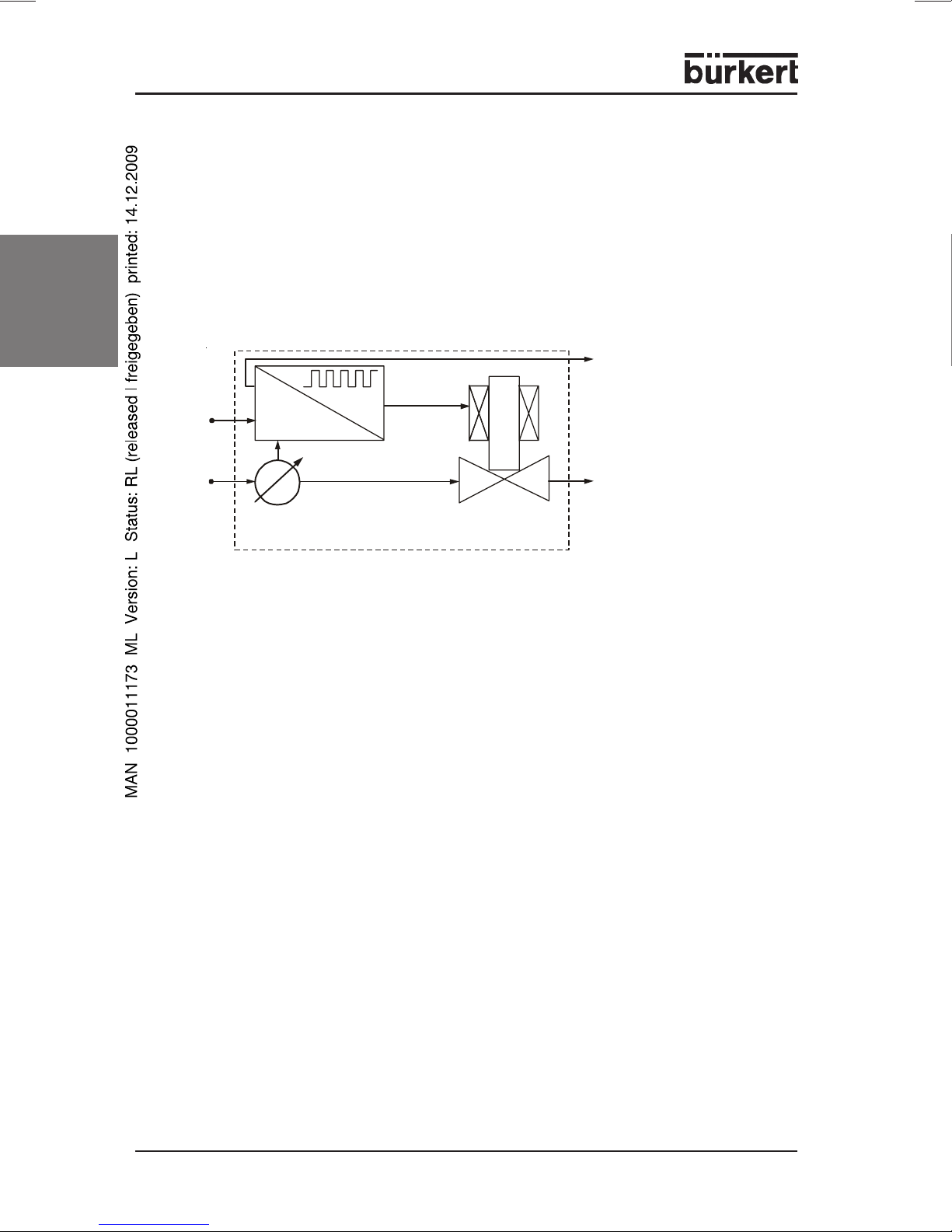
The MFCs contain the components flow rate sensor (Q sensor), electronics (with
the functions signal processing, control and valve drive), and a proportional
solenoid valve as the servo component.
english
w
p
Fig.: Components of a Mass Flow Controller
The setpoint value (w) is set electrically via a standard signal or a field bus. The
process value (x) measured by the sensor is compared in the controller with the
setpoint value. The correcting variable is sent as a plus-width modulated voltage
signal to the servo component. The pulse-duty factor of the voltage signal is varied
according to the control deviation determined.
The process value, in addition, is sent out via an analog electrical interface or a
field bus and is available to the user for monitoring purposes or further evaluation
(e.g. calculation of consumption by integration).
xd=w-x
x
Q sensor
controller
x
out
y
servo
component
The thermal measurement principle guarantees that the MFCs control to the
required mass flow to a large extent independently of pressure and temperature
variations in the respective application.
The MFMs, in contrast to the corresponding MFCs, do not have a proportional
valve, so that these devices can only be used to measure the mass flow and not
to control it. The characteristics of the other components, described in the
following, in particular the sensors, are identical with those of the MFCs.
8 - MFC/MFM
Page 9

Sensors
Thermal measurement principle
The flow sensors employed work on a thermal (anemometer) measurement
principle.
They measure in each case the product of density an flow velocity and thus deliver a signal related to the quantity of material flowing. For most applications the
relevant quantity
measurement of secondary quantities, such as density, and the signal can be
further processed in the controller as the process value1).
Depending on the flow rate range and the intended market for the devices, the
individual types contain sensors with three different variants of flow rate
measurement. In the following, the functioning and associated characteristics of
these sensors are briefly described.
mass flow
is directly determined thereby, without additional
english
NOTE
Please take into account that the relative sensitivity for different
gases differs for the three measurement principles and any
correction factors existing for one operating gas to another are in no
case transferable between sensor variants.
1)
It is true that the units generallly used for characterizing the measurement range, „lN/min“ or „m
dimensions "volume/time", but because of the reference to a standard state (here p=1013 mbar and
T=273 K), we are actually dealing with mass flow rates specific to gas types. These are obtained (e.g. in „kg/h“)
by multiplication of the standard volumetric flow rate by the density of the operating gas in the standard state ρN .
3
/h“ , have the
N
MFC/MFM - 9
Page 10
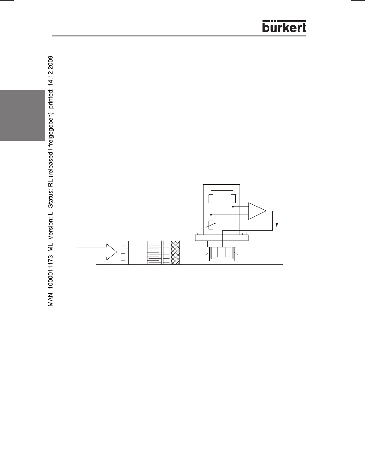
Inline sensor (Types 8626 / 8006 / 8716 / 8706)
This sensor works as a hot-film anemometer in the so-called CTA
Temperature Anemometer)
coefficients in the medium flow form a resistance bridge with three resistors
situated outside the flow.
The first resistor in the medium flow (RT) measures the fluid temperature; the
second, lower resistance resistor (RS) is always heated to maintain its
temperature a certain amount above that of the medium. The heating current
required is a measure of the heat dissipation by the flowing gas and represents
the primary measurement value.
english
Suitable flow conditioning inside the MFC or MFM and calibration with high-quality
flow standards guarantee that the quantity of gas flowing per unit time can be
derived with high precision from the primary signal.
(Constant
mode. Two resistors with exactly defined temperature
sensor with
electronics
R2R
R
K
1
PID
I
s
gas flow
prefilter
Fig.: Functional diagramm of the Inline sensor
flow conditioning
R
T
R
s
Direct medium contact by the resistors RT and RS in the main flow assure
excellent dynamics for the devices with response times of a few hundred
miliseconds on sudden changes in the setpoint or process value. Owing to the
arrangement of the resistors on a glass support lying tangential to the flow, the
sensor is only slightly prone to contamination. The measurement range of the
Inline sensor is limited at the bottom end by instrinsic convection in the flow
channel, which also occurs when the control valve is closed. It is hece unsuitable
for devices whose working range must extend to flow rates below ca. 1 lN/min.
The signal from intrinsic convection in the flow channel depends on the installation
position of the device. In order that high precision can be obtained at low flow
rates, the actual installation position should be identical to that specified on
ordering1). For the same reason, the operating pressure should not differ too much
from the calibration pressure.
1)
The device is calibrated in the installation position stated in the questionnaire to be found in the Annex to the Data
Sheet.
10 - MFC/MFM
Page 11
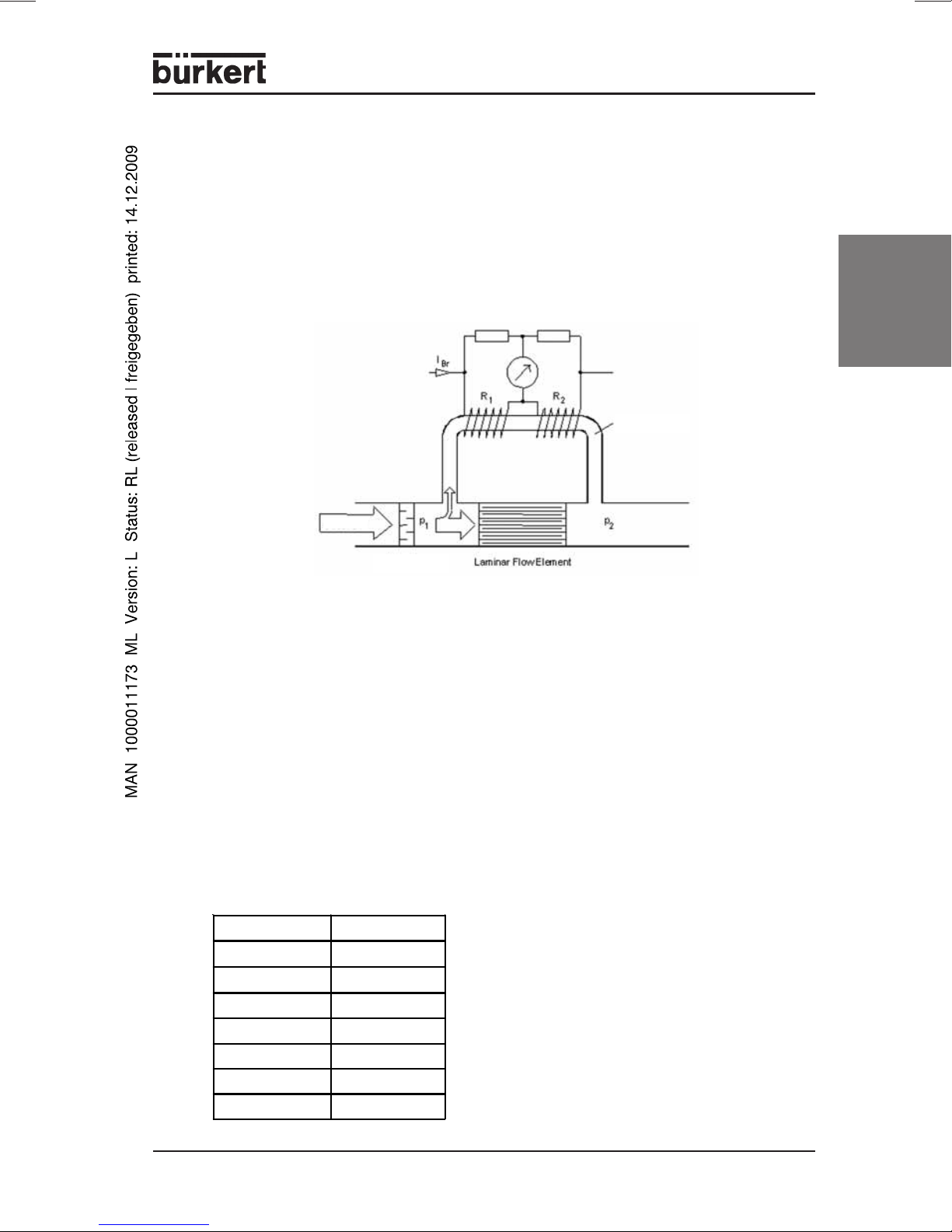
Bypass sensor in conventional technology "capillary"
(Types 8710 / 8700)
Measurement is also on the bypass principle. A laminar flow element in the main
channel generates a small pressure drop. This drives a small flow proportional to
the main flow through the actual sensor tube.
On this narrow tube are wound two heater resistors which are connected in
measuring bridge. In the zero-flow state, the bridge is balanced, but with finite flow,
heat is transported in the flow direction and the bridge becomes unbalanced.
sensor tube
gas flow
prefilter
english
Fig.: Schematic diagram of bypass measurement
The dynamics of the measurement are determined by the tube walls, which act as
a thermal barrier. They are hence significantly poorer, on principle, than with
sensors having resistor placed directly in the medium flow. Through use of suitable
software in the controller, correction times are obtained that are adequate for a
large part of the applications (in the range of a few seconds).
With contaminated media, we recommend installing filter elements upstream. This
avoids changes in the division ratio between main flow and sensor tube, as well as
changes in the head transmission chaused by deposits on the walls.
With these sensors, even aggressive gases can be controlled, since all essential
parts in contact with the medium are fabricated in stainless steel. With this sensor
prinziple it is also possible to convert between different gases. A choice of some
gases are listed in the table below, others on request. Q(gas) = f x Q (N2).
Gas Factor f
N
2
1.00
Air 1.00
O
H
2
2
0.99
1.01
By using the gas factors it is possible
that the accuracy is not within the
datasheet specification. For applications
which need high accuracy it is
recommended to calibrate under
application conditions.
Ar 1.4
He 1.41
CO
2
0.76
MFC/MFM - 11
Page 12
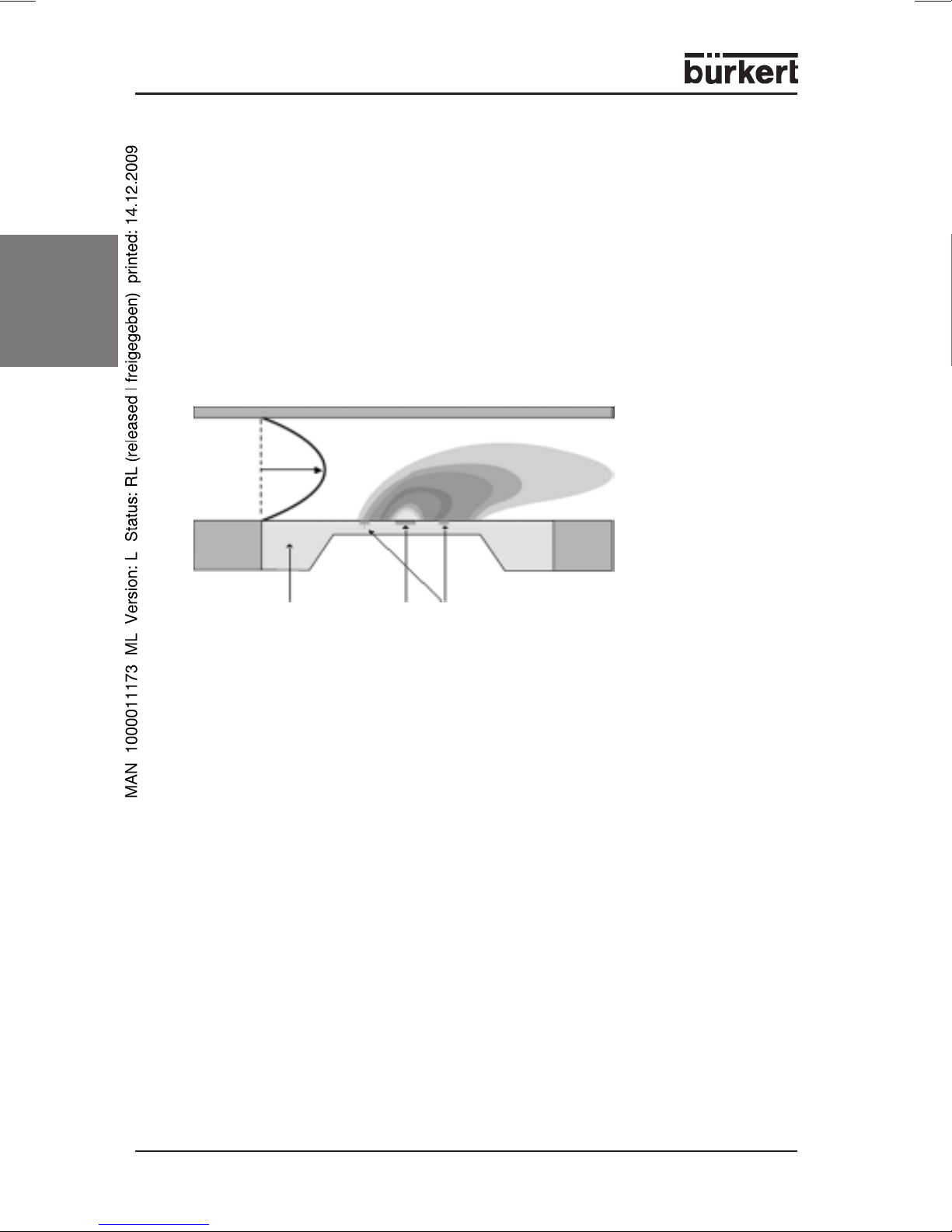
Bypass sensor in CMOSens® technology
(Types 8713 / 8703 / 8712 / 8702 / 8711 / 8701)
In this technology, the mass flow is measured in a specially shaped flow channel
whose wall contains at one point a Si chip with a membrane that has been formed
by etching. To this membrane are applied, in CMOSens® technology, a heating
resistor and two temperature sensors, arranged symmetrically upstream and
downstream of the heater.
When the heating resistor is fed with a constant voltage, the voltage difference
between the temperature sensors is a measure of the mass flow of the gas
english
flowing in the channel over the chip.
gas flow
sensor element heater T sensors
Fig.: Schematic diagram of the bypass sensor in CMOSens® technology
The cross-section of the flow channel is small enough that an adequate
measurement signal is generated already at flow rates of less than 1 cm
3
N
/min.
The upper measurement limit is reached when the originally laminar flow in the
channel becomes turbulent. Higher flow ranges can be obtained by placing a
bypass element in a larger channel which is connected in parallel. When the
division ratio remains constant, measurement of the partial flow, after suitable
calibration, allows the total flow to be calculated.
The low thermal mass of the temperature sensors and their direct contact with the
flow (apart from a protective layer) result in a very fast reaction of the sensor
signal to spontaneous changes in the flow. In this way, the MFC can compensate
changes in the setpoint or process value within a few 100 ms. Moreover, the
sensor has a high sensitivity down to the smallest flow rates as well as additional
correction and diagnostic possibilities via the signal from a further temperature
sensor on the chip.
12 - MFC/MFM
Page 13

Control electronics
Processing of the setpoint and actual flow signals, and drive of the actuator are
carried out by a microprocessor.
The sensor signal is filtered by the control electronics and with the aid of the
calibration curve stored in the device, converted to a value corresponding to
actual flow rate.
In order that critical process, in which a too great flow change is not permitted, can
also be controlled, a ramp function can be activated via the software
"MassFlowCommunicator" (see Appendix C). Here the parameters for rising and
sinking setpoinds can be set separately. Further details on the ramp function can
be taken from the software documentation.
Actuating signal:
actuating signal = setpoint - process value
xd = w - x
The actuating signal is processed according to a PI algorithm.
The control parameters are set in the factory according to type. In order to take
into account the characteristics of the controlled member, the controller works with
member-dependent amplification factors. During the running of the Autotune
routine, these are determined automatically.
english
In the device a parameter is stored with which the control dynamics can be altered
with the software "MassFlowCommunicator". Its extreme values correspond on
the one hand to very rapid correction, whereby overswing is possibly accepted,
and on the other hand to a slow asymptotic correction to the desired flow rate. The
first can lead to immediate reaction of the controller to very small actuating signals,
whereby the control can become very unsteady. With less dynamic processes,
the controller behaviour can be damped, so that small variations in the process
value or setpoint are corrected only slowly.
As the correcting variable, a pulse-width modulated (PWM) signal is sent to the
proportional valve. The frequency of this signal is adapted to the respective valve.
To assure the tight-closing function of the valve, zero-point switch-off is built in.
This becomes active if the following conditions simultaneously occur:
setpoint < 2 % of nominal flow
and process value < 2 % of nominal flow
1)
With the zero-point switch-off activated, the PWM signal is set to 0 %, so that the
valve closes completely.
1)
With types 8711 / 8712 / 8713 higher control ranges on request.
MFC/MFM - 13
Page 14

Depending on the version of the device, the setpoint is set either via the standard
signal input as an analog signal, or digitally via the field bus interface. Independent
of the control status, the flow rate measured by the sensor is sent as an analog
signal via the standard signal input or digitally via the field bus interface.
In order to obtain a dynamic or a more sluggish process value output signal, the
degree of filtering of the output signal can be adjusted with the software
"MassFlowCommunicator".
Proportional valve
english
In all MFC series, the servo elements used are linear-armature proportional
valves from the Bürkert valve range. Design measures, especially with the valves
in the MFC for low flow rate (Types 8710 / 8711 / 8712 / 8713), assure low-friction
guidance of the moving armature. In combination with the PWM drive, this assures
a continuous, largely linear characteristic curve as well as high response
sensitivity. Both are important for optimal functioning in the closed control loop of
the MFC.
The nominal diameters of the valves are determined from the required nominal
flow rate Q
operating gas.
, the pressure conditions in the application and the density of the
nom
The manufacturer selects a proportional valve on the basis of these data whose
flow coefficient k
enables a maximum flow rate of at least the required nominal
Vs
flow rate under the specified pressure conditions, according to flow equations:
a) for subcritical flow (p2 > p1/2) :
Q
max
= 514 *
∆
ρ
N
**T
2
pp
1
* kVs > Q
nom
(1)
or
b) for supercritical flow (p2 < p1/2) :
1
Q
= 257 *
max
ρ
Where the pressures p1 and p2 in equations (Gl.) (1) and (2) refer to
measurement points directly before and after the MFC.
The pressures before and after the MFC are often unknown, only the inlet and
outlet pressures p
*
p
occurs over other flow resistances (isolation valves, nozzles, piping, filters,
2
*
and p
1
etc.) whose flow coefficient may be collected together in a variable kVa.
* p1* kVs > Q
1*
TN
*
for the overall system. A part of the pressure drop p
2
nom
(2)
*
-
1
14 - MFC/MFM
Page 15

In this case, in analogy to equations (1) and (2), one first determines from the
ψ
desired nominal flow rate Q
coefficient of the overall system k
and the pressures p
nom
. Via the relationship
Vges
*
and p
1
*
, the minimum flow
2
2
⎛
(3)
⎜
⎜
⎝
which describes series connection of the resistances of the MFC (kVs) and the
system (kVa), one can determine, with known kVa, the required kVs value of the
MFC or the nominal diameter of the servo element. This will be greater than if the
other flow resistances were not present.
The so-called valve authority
is important for the control characteristics of the MFC in the system. It should not
be less than 0.3 ... 0.5.
Meaning of the symbols in the equations:
k
Vges
k
Va
⎞
⎟
=
⎟
⎠
()
p
∆
=
0
()
p
∆
0
flow coefficient of the system with MFC installed
flow coefficient of the system with MFC not installed (to be determined by
"short-circuiting" the piping at the point of installation)
⎞
⎛
⎜
⎜
⎝
=
[]
⎛
⎟
⎜
+
⎟
⎜
⎠
⎝
2
k
VsV
kk
+
22
⎞
111
⎟
⎟
kkk
VaVsVges
⎠
22
VsVa
(4)
english
k
flow coefficient of the MFC with fully opened servo element in [m³/h]
Vs
ρ
density of the medium in [kg/m3] under standard conditions (1013 mbar,
N
273 K)
T
temperature of the gas in K
1
p1, p2absolute pressures in [bar] before and after the MFC
∆p = p1 - p
Q
max
Q
nenn
(∆p)0pressure drop over the entire system
(∆p)V0fraction of the pressure drop occurring over the MFC with the valve fully
2
maximum flow rate of the valve in [lN/min]
maximum flow rate of the MFC in [lN/min] when correction to 100 % of
the setpoint has been made
open
MFC/MFM - 15
Page 16

NOTE
english
When the device is operated within the specified pressure range, the proportional
valve assumes the functions of both control and tight closure.
The system must not be dimensioned so closely with regard to the
flow coefficient (kVa) that at the desired flow rate, the major part of
the available pressure drop is used up there, and then the nominal
valve diameter of the MFC is chosen so great (kVs >> kVa) that only
the small remaining part of the pressure is dropped over the MFC. In
this case, the valve authority would be too small and only a small
part of the working range of the valve utilized. That could be greatly
detrimental in general to the resolution and control performance.
If the system has been dimensioned „to closely“, increasing the
nominal diameter of the MFC valve does not help. In this case an
increase either in the admission pressure or the kVa value should be
made, e.g. by increasing the pipe diameter, to keep the valve
authority within the permitted range.
16 - MFC/MFM
Page 17

TECHNICAL DATA
Environmental tests
• Temperature cycles to EN 60068-2-14, Nb and EN 60068-2-33
• Head and humidity to EN 60068-2-38, Z/AD
• Shocks to EN 60068-2-27
• Vibration to EN 60068-2-6
• IP protection type to EN 60529
• Free fall to EN 60068-2-32
• UPS fall test to DIN ISO 2248 and DIN ISO 2206
Electromagnetic compatibility (EMC)
All devices are CE conforming for industrial use and have passed the associated
EMC tests to
EN 50081-2:03/94 „Basic engineering standard for interference emission;
Part 2: Industrial domain“
EN 50082-2:02/96 „Basic engineering standard for interference resistance;
Part 2: Industrial domain“.
Communications interface
RS232: direct connection to PC via RS232 adapter, communication with special
software (MassFlowCommunicator – siehe Appendix C).
With 8711 / 8701, 8713 /8703 and 8710 / 8700, an external inferface
driver is necessary (integrated in adapter for these types - see
Appendix A).
RS485: connection via RS485 adapter (excerpt types 8713 / 8703)
BUS: Profibus DP or DeviceNet connection (bus devices only)
english
Seal material
FKM (other materials on request)
The compatibility of the seal material with the usual operating media can be taken
from the Bürkert stability tables.
ATTENTION!
The data given in this table are provided for information and
cannot replace own tests under the actual operating
conditions. In particular, no guarantee for medium compatibility
can be derived thereform.
MFC/MFM - 17
Page 18
Type 8626 / 8006 MASS FLOW INLINE
Full scale range (Q
Operating media neutral, not-contaminated gases, others on request
max. operating pressure 10 bar, depending on nom. valve diameter
Calibration medium operating gas or air
Medium temperature -10 to + 70 °C
Measurement accuracy
(after 15 min. warm-up)
english
Linearity ± 0.25 % of F.S.
Reproducibility ± 0.1 % of F.S.
Control range / Span 1 : 50
Settling time (T
Operating voltage 24 V DC ± 10 %; residual ripple < 5 %
Connection cross-section min. 0.5 mm² (0.75 mm² for valve Type 2836)
Power consumption 20 W - max. 50 W (Type 8626,dep. on Valve)
Electrical isolation yes
Setpoint setting
3 binary inputs low-activated, connect to GND to activate
Process value output
(to be chosen)
Connections 8-pole socket
Housing material aluminium (anodized) or stainless steel 1.4305
Cover material aluminium diecasting, painted
Installation position horizontal or vertical
) 25 to 1500 IN/min (N2 equivalent)
nom
Ambient temperature -10 to + 45 °C
± 1.5 % of Rdg. ± 0.3 % of F.S.
) < 500 ms
95%
22.5 W - max. 52.5 W (Type 8626 bus, dep. on
valve)
10 W (Type 8006)
12.5 W (Type 8006 bus)
0 - 10 V
(to be chosen)
0 - 5 V
0 - 20 mA
4 - 20 mA
Resolution 2.5 mV or 5 µA
Input impedance
> 20 kOhm
(voltage input)
Input impedance
< 300 Ohm
(current input)
0 - 10 V
0 - 5 V
0 - 20 mA
4 - 20 mA
Resolution 10 mV or 20 µA
max. current (volt. outp.)
10 mA
max. burden (curr. outp.) 600 Ohm
2 relay outputs potential-free changeover 60 V, 1 A, 60 VA
15-pole SUB-HD socket
9-pole SUB-D socket (bus version only)
Type of protection IP 65 (with the specified plug connectors)
18 - MFC/MFM
Page 19

Type 8710 / 8700 MASS FLOW CMOSens
®
Full scale range (Q
) 0.005 to 1.0 IN/min (N2 equivalent)
nom
Operating media neutral, not-contaminated gases, others on request
max. operating pressure
(inlet)
10 bar (145 psi), depends on valve orifice
Calibration medium operating gas or air with conversion factor
Medium temperature -10 to + 70 °C
Ambient temperature -10 to + 50 °C
Measurement accuracy
(after 30 min. warm-up)
± 1.5 % of Rdg. ± 0.3 % of F.S.
Linearity ± 0.25 % F.S.
Reproducibility ± 0.1 % F.S.
Control range / Span 1 : 50
Settling time (T
)< 3 sec.
95%
Power supply 24 V DC ± 10 %; residual ripple < 5 %
Connection cross-section min. 0.25 mm² (better 0.5 mm²)
Power consumption max. 6.5 W (dep. on value) /
max. 9 W (fieldbus version)
Electrical isolation no
Setpoint setting
(to be chosen)
0 - 10 V
0 - 5 V
0 - 20 mA or 4 - 20 mA
Resolution 2.5 mV or 5 µA
Input impedance
> 20 kOhm
(voltage input)
Input impedance
< 300 Ohm
(current input)
2 binary inputs low-activated, connected to GND to activate
Process value output
(to be chosen)
0 - 10 V
0 - 5 V
0 - 20 mA or 4 - 20 mA
Resolution 10 mV or 20 µA
max. voltage
10 mA
(voltage output)
max. burden
600 Ohm
(current output)
2 Relay output potential-free changeover 25 V, 1 A, 25 VA
Connection 15-pole Sub-D-plug
5-pole M12 plug (only with DeviceNet)
5-pole M12 socket (only with Profibus DP)
Type of protection IP 50
Housing material / Cover
material
Aluminium or stainless steel / PBT
Installation position horizontal or vertical
english
MFC/MFM - 19
Page 20

Type 8711 / 8701 MASS FLOW CMOSens
®
Full scale range (Q
max. operating pressure
(inlet)
Medium temperature -10 to + 70 °C
Measurement accuracy
english
(after 1 min. warm-up)
Linearity ± 0.1 % F.S.
Reproducibility ± 0.1 % F.S.
Power Supply 24 V DC, ± 10 %; residual ripple < 5%
Power consumption max. 13 W (dep. on valve)
Electrical isolation no
(to be chosen)
) 0.02 to 50 lN / min (N2 equivalent)
nom
Operating media neutral, non-contaminated gases, others on request
10 bar (145 psi), depends on valve orifice
Calibration medium operating gas or air with conversion factor
Ambient temperature -10 to + 50 °C
± 0.8 % of Rdg. ± 0.3 % F.S.
Control range / Span 1:50, higher span on request
Settling time (T
Connection cross-section min. 0.25 mm
Setpoint setting
) < 300 ms
95%
0 - 10V
2
(better 0.5 mm2)
0 - 5 V
0 - 20 mA or 4 - 20 mA
Resolution
Input impedance
2.5 mV or 5 µA
> 20 kOhm
(voltage input)
Input impedance
< 300 Ohm
(current input)
2 binary inputs Low-activated, connected to GND to activate
Process value output
(to be chosen)
0 - 10V
0 - 5 V
0 - 20 mA or 4 - 20 mA
Resolution
Max. voltage
10 mV or 20 µA
10 mA
(voltage output)
max. Burden
600 Ohm
(current output)
1 Relay output Potential-free changeover 25 V, 1 A, 25 VA
Connection 15-pole Sub-D-Socket
5-pole M12 plug (only with DeviceNet)
5-pole M12 socket (only with Profibus DP)
Type of protection IP 50
Housing material /
Cover material
Aluminium or stainless steel / sheet steel, chrome
plated or PBT
Installation position horizontal or vertical
20 - MFC/MFM
Page 21

Type 8712 / 8702 MASS FLOW CMOSens
®
Full scale range (Q
Operating media
) 0.02 to 50 lN/min (N
nom
neutral, non-contaminated gases,
others on request
equivalent)
2
max. operating pressure 10 bar, depending on nom. valve diameter
Calibration medium operating gas or air
Medium temperature -10 to + 70 °C
Ambient temperature -10 to + 50 °C
Measurement accuracy
± 0.8 % of Rdg. ± 0.3 % of F.S.
(after 1 min. warm-up)
Linearity ± 0.1 % of full scale
Reproducibility ± 0.1 % of full scale
Control range / Span 1 : 50; higher span on request
Setting time (T
) < 300 ms
95%
Operating voltage 24 V DC ± 10 %; residual ripple < 5 %
Connection cross-section min. 0.25 mm² (better 0.5 mm²)
Power consumption max. 6.5 W (Type 8712)
max. 9 W (Type 8712 bus)
2.5 W (Type 8702)
5 W (Type 8702 bus)
Electrical isolation yes
Setpoint setting
(to be chosen)
0 ... 10 V
0 ... 5 V
0 ... 20 mA
4 ... 20 mA
Resolution 2.5 mV or 5 µA
Input impedance
> 20 kOhm
(voltage input)
Input impedance
< 300 Ohm
(current input)
3 binary inputs low-activated, connect to GND to activate
Process value output
(to be chosen)
0 ... 10 V
0 ... 5 V
0 ... 20 mA
4 ... 20 mA
Resolution 10 mV ou 20 µA
max. current (voltage outp.) 10 mA
max. burden (curr. outp.) 600 Ohm
2 relay outputs potential-free changeover 60 V, 1 A, 60 VA
Connections 8-pole socket
15-pole SUB-HD socket
9-pole SUB-D socket (bus version only)
Type of protection IP 65 (with the specified plug connectors)
Housing material
Cover material
stainless steel 1.4305
PBT
Installation position horizontal or vertical
english
MFC/MFM - 21
Page 22

Type 8713 / 8703 MASS FLOW CMOSens
®
Full scale range (Q
Operating media neutral, non-contaminated gases, others on request
Max. operating pressure
(inlet)
Calibration medium Operating gas or air with conversion factor
Medium temperature -10 to + 70 °C
Ambient temperature -10 to + 50 °C
Measurement accuracy
english
(after 1 min. warm-up)
Linearity ± 0.1 % F.S.
Repeatability ± 0.1 % F.S.
Control range/ Span 1 : 50; higher span on request
Settling time (T
Power Supply 24 V DC ± 10 %; residual ripple < 5 %
Connection cross-section min. 0.25 mm² (better: 0.5 mm²)
Power consumption max. 6.5 W
Electrical isolation yes
Setpoint setting Digital communication via RS 485
1 binary input Low-activated, connected to GND to activate
Process value output Digital communication via RS 485
1 relay output Potential-free changeover 25 V, 1 A, 25 VA
Connections 9-pole Sub-D-plug
Type of protection IP 50
Housing material
/ Cover material
Installation position horizontal or vertical
) 0.02 to 50 lN/min (N2 equivalent)
nom
10 bar (145 psi), depends on valve orifice
± 0.8 % of Rdg. ± 0.3 % F.S.
) < 300 ms
95%
Aluminium or stainless steel 1.4305 / sheet steel,
chrome plated
22 - MFC/MFM
Page 23

Type 8716 / 8706 MASS FLOW INLINE
Full scale range (Q
8706
8716
nom
)
25 to 1500 l
25 to 500 l
/min (N2 equivalent)
N
/min (N2 equivalent)
N
Operating media neutral, non-contaminated gases, others on request
max. operating pressure 10 bar, depending on nom. valve diameter
Calibration medium operating gas or air with conversion factor
Medium temperature -10 to + 70 °C
Ambient temperature -10 to + 45 °C
Measurement accuracy
± 1.5 % of Rdg. ± 0.3 % F.S.
(after 15 min. warm-up)
Linearity ± 0.25 % F.S.
Reproducibility ± 0.1 % F.S.
Control range / Span 1 : 50
Settling time (T
) < 500 ms
95%
Operating voltage 24 V DC ± 10 %; residual ripple < 5 %
Connection cross-section min. 0.5 mm²
20 W - max. 30 W (Type 8716 dep. on valve)
Power consumption
22.5 W - max. 32.5 W (Type 8716 bus,dep. on valve)
10 W (Type 8706)
12.5 W (Type 8706 bus)
Electrical isolation yes
Setpoint setting
(to be chosen)
0 - 10 V, 0 - 5 V, 0 - 20 mA,
4 - 20 mA
english
Resolution 2.5 mV or 5 µA
Input impedance
> 20 kOhm
(volt. inp.)
Input impedance
< 300 Ohm
(curr. inp.)
3 binary inputs low-activated, connect to GND to activate
Process value output
(to be chosen)
0 - 10 V
0 - 5 V
0 - 20 mA
4 - 20 mA
Resolution 10 mV or 20 µA
max.current (volt. outp.) 10 mA
max. burden (curr. outp.) 600 Ohm
2 relay outputs potential-free changeover 60 V, 1 A, 60 VA
Connections 8-pole socket
15-pole SUB-HD socket
9-pole SUB-D socket (bus version only)
Type of protection IP 65 (with the specified plug connectors)
Housing material aluminium (anodized) or stainless steel 1.4305
Cover material PBT
Installation position horizontal or vertical
MFC/MFM - 23
Page 24
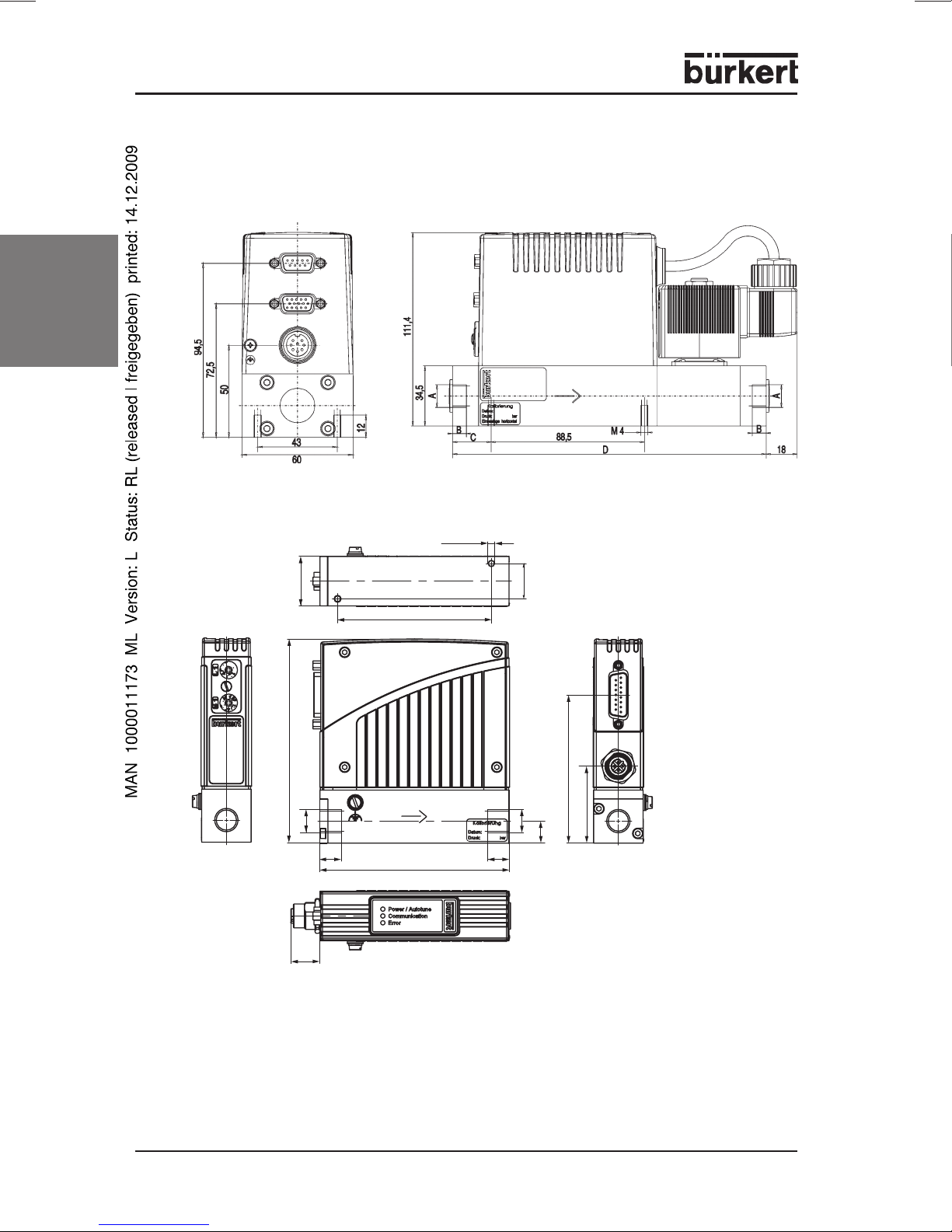
ASSEMBLY, INSTALLATION AND COMMISSIONING
Dimensional drawings
english
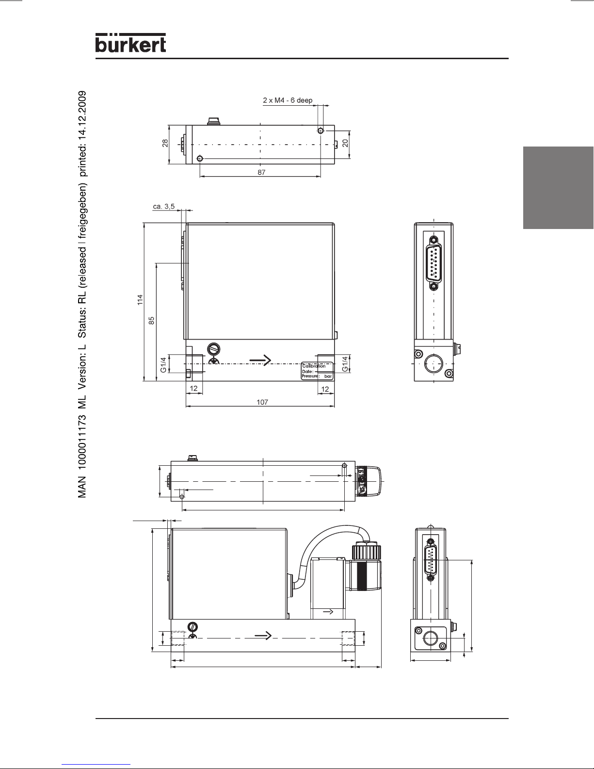
Fig.: Type 8626 / 8006 MASS FLOW INLINE (version with proportional valve 6022 and standard sensor body)
2 x M
4
- 6 deep
28
87
115,5
A
Bus version
Fig.: Type 8710 / 8700 MASS FLOW CAPILLARY / Type 8711/8701 MASS FLOW CMOSens
16,5
12
Bus version
107
12
20
84
43,5
A
12,5
Bus version
®
24 - MFC/MFM
Page 25
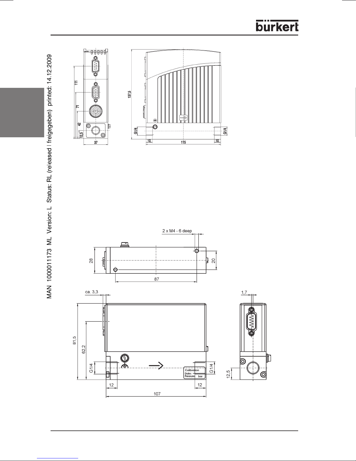
english
Fig.: Type 8711 / 8701 MASS FLOW CMOSens
29
ca. 3.5
114
Fig.: Type 8711 with external valve
A
12
M4 - 6 deep
150
170
®
(with steel sheet housing)
M4 - 6 deep
A
12
ca. 24
85
12.5
37
MFC/MFM - 25
Page 26
english
Fig.: Type 8712 / 8702 MASS FLOW CMOSens
®
Fig.: Type 8713 / 8703 MASS FLOW CMOSens
26 - MFC/MFM
®
Page 27
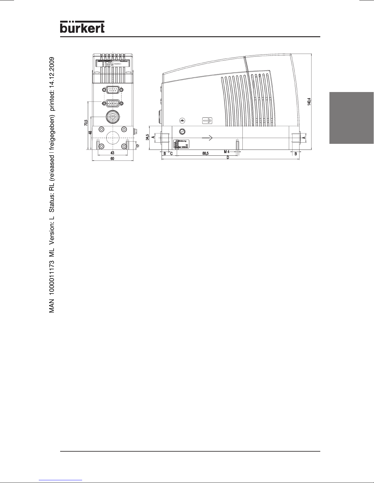
Fig.: Type 8716 / 8706 MASS FLOW INLINE (with standard sensor body)
english
MFC/MFM - 27
Page 28
General notes on installation and operation
Before installation:
english
Proceed in the following sequence on commissioning an MFC/MFM:
1. Mechanical and fluidic installation
2. Electrical installation
3. Pressurize with operating medium
4. Regular working operation
NOTE The specified precision will be obtained only when, after switching on,
Install a suitable filter upsteam to assure cleanliness of the operating
medium.
Observe the installation position (see calibration data).
Provide a power supply with adequate power.
Observe the max. residual ripple on the operating voltage.
Remove dirt from the piping before installation of the MFC.
the thermal equilibration processes have been completed and the
device has reached its operating temperature (the time required
depends on the device type, see
Technical Data
).
28 - MFC/MFM
Page 29
Operation with additional isolation valve
The proportional valve integrated into the MFC assumes the tight-closure function,
so that an additional isolation valve is not required in the medium circuit. If for
safety reasons, however, an additional isolation valve is placed before or after the
MFC, the drive sequence should be as follows:
Start
1. Connect pressure supply
2. Open isolation valve
3. Set MFC setpoint (normal control operation)
Shut-down
1. Set MFC setpoint to 0 %
2. Close isolation valve when process value of 0 % is reached
Any other sequence could result, on renewed opening of the isolation valve, even
with setpoint zero, in a short flow pulse or, on first setting of the setpoint, significant
overswing.
Mechanical and fluidic installation
Select the available fluidic connections to match the maximum flow rate. Intake
sections are not required. If necessary, we can also supply special sizes,
whereby the dimensioning of the fluidic system with regard to flow and pressure
drop must be taken into account.
english
Fluidic connections
The device can on request also be supplied with screw-in joints already
assembled. Please select the matching fluidic connection from the table in Appendix B.
Connections at MFC/MFM
Types
8626
8006
8716
8706
8713
8703
8712
8702
8711
8701XX
8710
8700
G 1/4" G 3/8" G 1/2" G 3/4" NPT 1/4 NPT 3/8 NPT1/2 NPT3/4
Standard screw-in thread Special screw-in thread
X
X
X
X
X
X
X
X
X
X
X
X
X
X
X
X
X
X
X
X
X
X
X
X
X
X
X
X
X
X
X
X
X
X
X
X
X
X
X
X
X
X
Sub
base
X
X
X
X
X
X
X
X
X
X
X
X
MFC/MFM - 29
Page 30
Assembly of clamping ring screw joints
ATTENTION!
In order to seal the system properly, proceed as follows:
english
Electrical connections
With low flow rates and high pressures, pay attention to the
gastightness of the system to avoid false dosage or gas
leakage.
Mount pipe connections without stress (using compensators if necessary).
Use piping with matching diameter and smooth surface.
Cut off the piping at right angles and deburr.
Slide coupling ring, support ring (if present) and clamping ring onto the
piping in that order.
Insert piping into joint as far as it will go.
Union firmly tighten.
Counter with a wrench on the screw-in side (do not load the device
housing) and tighten by 1 ¼ turns.
ATTENTION!
The MFCs/MFMs are operated with 24 V power supply. Select the connector
cross-section according to the valve used and as large as possible (see
Data
). Suitable connecting cables are to be found in Appendix A.
ATTENTION!
Connect the the functional earth (FE) to the marked screw, e.g. using
round pliers.
To assure electromagnetic compatibility (EMC), connect the
housing via as short a cable as possible (with as large a
cross-section as possible) to the functional earth (FE).
The GND or mass conductors of all signals of the MFC/MFM
must be led in each case individually to the MFC.
(If all GND signals are bridged directly at the MFC and only
one conductor led to the switching cabinet, signal
displacements and disturbances of the analog signals may
occur (pulses, oscillations, etc.)).
Technical
The 8-pole socket (types 8626 / 8006 / 8712 / 8702 / 8716 /
8706) only has to be tightened hand-screwed.
30 - MFC/MFM
Page 31

Connection configuration Type 8626 / 8006
8-pole socket (circular)
24V - supply +
1
Relay 1 - C contact
2
Relay 2 - C contact
3
Relay 1 - NC contact
4
Relay 1 - NO contact
5
24V - supply GND
6
Relay 2 - NO contact
7
Relay 2 - NC contact
8
9-pole Sub-D socket (bus version only)
PROFIBUS DP DeviceNet
1
N. C. (not connected) CAN_L data line
2
RxD/TxD-P B-line GND
3
RTS control signal for repeater N. C.
4
GND data transmission potential N. C.
5
VDD
6
supply voltage + (P5V)
N. C. CAN_H data line
7
RxD/TxD-N A-line N. C.
8
N. C. N. C.
9
+15 pole Sub-HD socket
Analog drive Bus version
Setpoint input + N. C.
1
Setpoint input GND N. C.
2
Process value output + N. C.
3
4
5
6
7
8
9
10
11
12
Process value output GND N. C.
13
14
15
Shield (FE) functional earth
N. C.
Binary input 2
12 V output (for factory unse only)
RS232 TxD (direct connection to PC)
Binary input 1
DGND (for binary inputs)
For factory use only (do not connect!)
12 V output (for factory use only)
12 V output (for factory use only)
Binary input 3
RS232 RxD (direct connection to PC)
DGND (for RS232 interface)
english
NOTE
If a device of Type 8626 / 8006 (built before 2003) is to be replaced
by a new one (from 2003 on), this can be done by using an adapter
(see Appendix A) without additional cabling.
MFC/MFM - 31
Page 32

Connection configuration Type 8710 / 8700
english
9
10
11
12
13
14
15
15-pole Sub-D plug
Relay output - NC contact
1
Relay output - NO contact
1
2
3
4
5
6
7
8
2
Relay output - C contact
3
GND 24 -V-supply and binary inputs
4
24 V supply +
5
8 V output (For factory use only!)
6
Setpoint input GND
7
Setpoint input +
8
Process value output GND
9
Process value output +
10
DGND (for RS232)
11
Binary input 1
12
Binary input 2
13
RS232 RxD (without driver)
14
RS232 TxD (without driver)
15
Only with fieldbus
Profibus DP-socket B-encoded M12
1
5
2
(DPV1 max. 12 Mbaud)
1VDD
2 RxD / TxD - N (A-line)
4
3DGND
4 RxD / TxD - P (B-line)
3
5
2
5 Shield
DeviceNet - plug M12
1 Shield
1
3
4
2VDD
3DGND
4CAN_H
5CAN_L
32 - MFC/MFM
Page 33

Connection configuration Type 8711 / 8701
15-pole Sub-D plug
Relay output - NC contact
1
Relay output - NO contact
2
Relay output - C contact
3
GND 24 -V-supply and binary inputs
4
24 V supply +
5
8 V output (For factory use only!)
6
Setpoint input GND
7
Setpoint input +
8
Process value output GND
9
Process value output +
10
DGND (for RS232)
11
Binary input 1
12
Binary input 2
13
RS232 RxD (without driver)
14
RS232 TxD (without driver)
15
9
10
11
12
13
14
15
1
2
3
4
5
6
7
8
english
Only with fieldbus
Profibus DP-socket B-encoded M12
1
5
2
(DPV1 max. 12 Mbaud)
1VDD
2 RxD / TxD - N (A-line)
3DGND
4
4 RxD / TxD - P (B-line)
5 Shield
3
5
2
DeviceNet - plug M12
1 Shield
1
2VDD
3DGND
3
4
4CAN_H
5CAN_L
MFC/MFM - 33
Page 34

Connection configuration Type 8712 / 8702
english
8-pole socket (circular)
24V - supply +
1
Relay 1 - C contact
2
Relay 2 - C contact
3
Relay 1 - NC contact
4
Relay 1 - NO contact
5
24V - supply GND
6
Relay 2 - NO contact
7
Relay 2 - NC contact
8
9-pole Sub-D socket (bus version only)
PROFIBUS DP DeviceNet
1
N. C. (not connected) CAN_L data line
2
RxD/TxD-P B-line GND
3
RTS control signal for repeater N. C.
4
GND data transmission potential N. C.
5
VDD
6
supply voltage + (P5V)
N. C. CAN_H data line
7
RxD/TxD-N A-line N. C.
8
N. C. N. C.
9
+15 pole Sub-HD socket
Analog drive Bus version
Setpoint input + N. C.
1
Setpoint input GND N. C.
2
Process value output + N. C.
3
4
5
6
7
8
9
10
11
12
Process value output GND N. C.
13
14
15
Shield (FE) functional earth
N. C.
Binary input 2
12 V output (for factory unse only)
RS232 TxD (direct connection to PC)
Binary input 1
DGND (for binary inputs)
For factory use only (do not connect!)
12 V output (for factory use only)
12 V output (for factory use only)
Binary input 3
RS232 RxD (direct connection to PC)
DGND (for RS232 interface)
34 - MFC/MFM
Page 35

Connection configuration Type 8713 / 8703
9-pin sub-D plug
Binary input (related to GND PIN 2)
1
GND
2
Power supply +24 V DC
3
Relay, C contact
4
Relay, NC contact
5
TX+ (RS485-Y)
6
bridge with pin 9 at Half-Dublex
TX- (RS485-Z)
7
bridge with pin 8 at Half-Dublex
RX- (RS485-B)
8
RX+ (RS485-A)
9
english
MFC/MFM - 35
Page 36

Connection configuration Type 8716 / 8706
english
8-pole socket (circular)
24V - supply +
1
Relay 1 - C contact
2
Relay 2 - C contact
3
Relay 1 - NC contact
4
Relay 1 - NO contact
5
24V - supply GND
6
Relay 2 - NO contact
7
Relay 2 - NC contact
8
9-pole Sub-D socket (bus version only)
PROFIBUS DP DeviceNet
1
N. C. (not connected) CAN_L data line
2
RxD/TxD-P B-line GND
3
RTS control signal for repeater N. C.
4
GND data transmission potential N. C.
5
VDD
6
supply voltage + (P5V)
N. C. CAN_H data line
7
RxD/TxD-N A-line N. C.
8
N. C. N. C.
9
+15 pole Sub-HD socket
Analog drive Bus version
Setpoint input + N. C.
1
Setpoint input GND N. C.
2
Process value output + N. C.
3
4
5
6
7
8
9
10
11
12
Process value output GND N. C.
13
14
15
Shield (FE) functional earth
N. C.
Binary input 2
12 V output (for factory unse only)
RS232 TxD (direct connection to PC)
Binary input 1
DGND (for binary inputs)
For factory use only (do not connect!)
12 V output (for factory use only)
12 V output (for factory use only)
Binary input 3
RS232 RxD (direct connection to PC)
DGND (for RS232 interface)
36 - MFC/MFM
Page 37

Inputs / outputs
Overview of types
Type Setpoint
input
8006 - X - 4 3 2
8626 X X - 4 3 2
8006 Bus - - X 4 3 2
8626 Bus - - X 4 3 2
8700 - X - 3 2 1
8710 X X - 3 2 1
8700 Bus - - X 3 2 1
8710 Bus - - X 3 2 1
8701 - X - 3 2 1
8711 X X - 3 2 1
8701 Bus - - X 3 2 1
8711 Bus - - X 3 2 1
8702 - X - 4 3 2
8712 X X - 4 3 2
8702 Bus - - X 4 3 2
8712 Bus - - X 4 3 2
8703 - - X 3 1 1
8713 - - X 3 1 1
8706 - X - 4 3 2
8716 X X - 4 3 2
8706 Bus - - X 4 3 2
8716 Bus - - X 4 3 2
Process
value output
BUS
connection
LED Binary
inputs
Relay
outputs
english
NOTE As an option you can obtain the PC software "Mass Flow
Communicator", with which you can switch over the standard signal
for the setpoint input and the process value output between 0 - 5 V,
0 - 10 V, 0 - 20 mA and 4 - 20 mA (see Appendix C).
Setpoint input
The setpoint input servec to enter the analog setpoint value via a standard signal
for the MFC.
Process value output
The process value output exits the current flow rate as a standard signal.
MFC/MFM - 37
Page 38

Bus connection
Types 8626, 8006, 8716, 8706, 8712, 8702, 8711, 8701, 8710 and 8700 are
available as bus versions. Setpoint and process value are received or repeated in
digital form via the bus. One can choose between a PROFIBUS DP and a
DeviceNet connection (see also
devices or serial communication RS 232 / RS 485
Supplement to Operating Instructions for fieldbus
).
LEDs to indicate the operating mode (deault configuration)
english
POWER LED lights The device is supplied with operating
LIMIT (y) LED lights With MFC:
ERROR LED lights Not a serious error, e.g. Autone not
voltage
flashes Autotune function activated
(green)
COMMUNICATION LED lights The device communicates via bus or RS-
interface.
(yellow)
indicates that the correcting variable of the
valve has almost reached 100 %. In
practice, this usually means that the
pressure at the controller is insufficient to
realize the desired flow rate.
With MFM:
indicates that the process value has almost
reached the nominal flow rate.
flashes The device is in an operating mode other
(blue)
than control or Autotune.
completed successfully or faulty LED.
Binary inputs (default configuration)
In order to initiate the event in each case, the binary input must be connected for
at least 0.5 s to DGND.
Functions
Binary input 1 Autotune function (not configured with MFM)
Binary input 2 not configured
Binary input 3 not configured
38 - MFC/MFM
flashes Serious error, e.g. sensor breakage or faulty
(red)
(not present with 8713 / 8703)
(with second gas calibration - change gas)
(not present with 8710 / 8700 / 8711 / 8701 / 8713 / 8703)
internal voltage supply.
Page 39

Binary outputs (default configuration)
The binary outputs are executed as realy outputs (potential-free changeover
contacts).
Functions
Relay 1** LIMIT (y)
Relay 2* ERROR (serious error, e.g. sensor breakage or faulty internal
voltage supply)
* (not present with 8710 / 8700 / 8711 / 8701 / 8713 / 8703)
* * (with 8713 / 8703 as normally closed contact)
english
NOTE
The functions of the POWER- and ERROR-LED are unchangable.
The described functions of the standard signal inputs and outputs
and the binary inputs and outputs are settings as delivered.
Applicationspecific settings of binary inputs and outputs
The MFCs additionally enables the user to set other or further functions to the
binary inputs and outputs. This option provides the opportunity to adapt the MFC to
special conditions in the facility or specific requirements of the application.
The functions can be set with the communication software
(MassFlowCommunicator – see Apendix C). The setting of the functions is
detailled explained in the help-function of the MassFlowCommunicator in the menu
item „Assignment of In- and Outputs“.
LEDs of the device
The LEDs which are integrated in the device display the staus of the setted
functions. Following functions can be setted to the LEDs:
- Display of the active used gascalibration
- Display of active binary inputs
- valve completely opened or closed
- control of safety value
- setpoint profile of the device is controlled
- Control operation active / inactive
- communication active / inactive
- source of setpoint - bus / serial communication
- several bus- or communicationstatus
(see help-function of the MassFlowCommunicator - „Assignment of In- and Outputs“)
MFC/MFM - 39
Page 40

Binary outputs
The binary outputs of the MFC, which can be defined specificly, can be used to
transfer information to a higher-level controller under certain circumstances.
The binary outputs enable to make predication of the device or can be used for
diagnostics and fixing malfunctions.
- Status of the device
english
- limit switches
autotune routine active
active used gascalibration
active binary inputs
status of bus module or bus communication
setpoint profile of the device is controlled
control operation active
control of safety value
valve completely opened or closed
Binary outputs are setted when the limit value (eg. totalizer limit value, set point
limit value etc.) is under- or overstepped.
- faults/malfunctions
Serveral faults and malfunctions can be reported, for example sensor
damages or faults with current or supply voltage.
(see help-function of the MassFlowCommunicator - „Assignment of In- and Outputs“)
Binary intputs
Defined functions can be set to the binary inputs. If the binary input is externally
activated the function is processed.
- activate autotune routine
- Switch to another gascalibration
- safety value active / inactive - control of safety value depending on the binary input
- setpoint profile of the device is controlled
- switch to control operation
- reset the totalizers
- open or close valve completely
(see help-function of the MassFlowCommunicator - „Assignment of In- and Outputs“)
40 - MFC/MFM
Page 41

Operating modes of the MFC
Standard control operation
This is the operating mode in which the MFC finds itself after being switched on
and after a short initialization phase. In the LED group, only the green Power LED
lights.
The flow rate is controlled to the setpoint with high sensitivity. Disturbances such
as those resulting from pressure variations are rapidly corrected by suitable
adjustment to the aperture of the control valve.
In this mode, the setpoint is set via the analog input (standard signal input) or the
field bus, depending on the version of the device.
The controller parameters are set such that changes in the process value or
distrubances are corrected as fast as possible without significant overswing being
caused.
english
NOTE
When the driving signal of the control valve approaches the
100 % limit, the LIMIT (y) LED lights. The cause is usually that
the pressure difference over the MFC is too small, e.g. because
the pressure supply is insufficient or the filter is heavily
contaminated. This can lead to non-achievement of the setpoint
and an enduring positive actuating signal (w-x). To enable an
external reaction to be made to this situation, a relay output is
actuated in addition.
Autotune routine
A prerequisiste for the automatic adaptation of the controller to the conditions in
the system is that the typical pressure conditions pertain.
Initiate the Autotune routine by operating the binary input 1.
The Autotune routine runs automatically. During this operation, the green POWER
LED flashes.
ATTENTION!
Observe the following points while the Autotune routine runs:
Various changes in flow occur.
The power supply of the MFC must not be switched off.
The supply pressure should be kept constant.
While the Autotune routine runs, the MFC does not control. The control valve is
driven according to an internally specified scheme. This leads to flow changes,
whereby some of the control parameters are adapted to the conditions pertaining
in the system. At the end of the Autotune routine, these parameters are stored in
the non-volatile memory of the device.
After completion of the Autotune routine, the MFC returns to the previous
operating mode.
MFC/MFM - 41
Page 42

NOTE
english
Safety function
This function can be activated or reset via a binary input or field bus, depending on
the device configuration.
In this operating mode, the device behaves in general as in standard control
operation. However, an externally applied setting is ignored and a defined safety
value is used as the setpoint (on default: 0 %; this can be changed with the PC
software MassFlowCommunicator).
Setpoint profile
Each MFC has been subjected to the Autotune routine in the factory
during final testing at the operating pressure stated in the calibration
report. For reliable control operation in a system, it is not absolutely
necessary to initiate this function again after commissioning. We
recommend renewed initialization if the operating pressure deviates
by serveral bar from the calibration pressure or if the characteristic
curve of the proportional valve is heavily influenced by a low valve
authority (see
be executed after significant changes in the pressure conditions in
the system.
Proportional Valve
). The Autotune routine should also
This function can be activated or reset via a binary input or field bus, depending on
the device configuration.
In this operating mode, the device behaves in general as in standard control
operation. However, the external setting is ignored and a previously definded
temporal sequence of up to 30 flow rates is used as the setpoint (configuration
with the PC software MassFlowCommunicator).
After completion of the setpoint sequence, the device returns to the previous
operating mode.
Control operation
This function can be activated or reset via a binary input or field bus, depending on
the device configuration.
In this operating mode, the setpoint is used as the starting value for the valve
pulse-duty factor,
e.g.: Setpoint = 10 % valve pulse-duty factor = 10 %.
42 - MFC/MFM
Page 43

Operating modes of the MFC
Operating
mode
Standard
control
operation
Control
operation
Setpoint profile · Autotune routine LIMIT (y) LED
Autotune
routine
can be interrupted
or ended by
· Autotune routine - -
· Safety function
· Setpoint profile
· Control operation
· Autotune routine LIMIT (y) LED
· Safety function
· Setpoint profile
· Safety function
· Device reset
· Safety function
· Device reset
LED display
of default
flashes
flashes
POWER LED
flashes
Reaching the operating
status via binary input
(if configured)
english
as long as activated
Initiate with activated
binary input ≥ 0.5 s
(if continuously
configured, repeated
starts)
Initiate with actifated
binary input ≥ 0.5 s
(if continuously
configured, repeated
starts)
Safety function - LIMIT (y) LED
flashes
as long as activated
MFC/MFM - 43
Page 44

MAINTENANCE
The MFC and MFM are in principle maintenance-free when operated according to
the notes given in these Instructions, so that routine recalibration is unnecessary.
If after prolonged operation with contaminated medium, large quantities of particles
were drawn in, with Types 8626 / 8006 / 8710 / 8700 / 8711 / 8701, 8712 / 8702 /
8713 / 8703 / 8716 / 8706 the easily accessible stainless steel filter can be
cleaned or replaced after removing the flange plate on the inlet side (see Appendix
B).
If the sensor is contaminated by the operating gas, the device may exhibit large
english
deviations from the required flow after prolonged operation. Cleaning and
recalibration in the factory will then be necessary.
ATTENTION!
The device must not be opened!
Inside the device there are further elements for flow
conditioning. Interference with the device, e. g. for cleaning, is
not permitted since the resulting changes in the sensor signal
would require recalibration in the factory!
44 - MFC/MFM
Page 45

MALFUNCTION / TROUBLESHOOTING
Problem Possible cause Remedy
"POWER" LED
does not light
"POWER" LED
flashes
"POWER" LED
extinguishes
periodically
"LIMIT (y)" LED
lights (only with
default
configuration)
"LIMIT (y)" LED
flashes (only with
default
configuration)
"ERROR" LED lights Less serious error has
"ERROR" LED
flashes
No flow present Setpoint within zero-point
No electrical supply Check the electrical
connections.
Autotune activated see Section
Operating Modes
Voltage supply collapses
periodically - device
executes reset
Loss on the connecting line
too high
MFC: correcting variable of
valve has reached almost
100 % - cannot correct to
setpoint.
MFM: process value has
almost reached nominal
flow rate.
Operating mode other than
standard control operation
or Autotune.
occurred:
- Last Autotune was not
completed successfully.
- A fault at an LED was
detected.
Residual ripple of supply
volate too high.
Serious error, e. g. sensor
breakage or faulty internal
voltage supply.
switch-off.
Different operating mode. Check the operating mode.
Select a power supply with
adequate power.
- Increase cable cross-section.
- Decrease cable length.
- Increase the supply
pressure.
- Check and if necessary
lower the piping resistance.
- Check system dimensioning
(see Section Proportional
Valve)
see Section
Operating Modes
- Repeat the Autotune or reset
the error.
- With errors at LED or binary
output, limited operation is
possible.
Select a suitable voltage
source (not industrial DC).
Send the device to the
manufacturer for repair.
Increase setpoint to > 2 % of
nominal flow.
english
Table continued on the next page.
MFC/MFM - 45
Page 46

Problem Possible cause Remedy
Process value varies No porper FE connection Connect the FE to the earthing
english
Controller tends to
oscillate
Setpoint value w = 0,
flow still present after
a few seconds
Setpoint value w = 0,
valve closed, no flow;
but process value
output shows a small
flow
Controller shows
strong overswing
starting after a step
in the setpoint of 0%.
In the case of flame
control, the flame
extinguishes after a
step in the setpoint.
Controller must
continuously correct
disturbances in an unstable
pressure supply.
Residual ripple of supply
voltage too high.
Operating pressure lies far
above that at which the last
Autotune was executed.
Control parameters do not
correspond to the section
behaviour.
A medium is being used
other than that intended on
calibration.
Residual ripple of supply
voltage too high.
Operating pressure above
the leak-tight pressure of
the proportional valve.
Operating pressure
significantly higher than
that used for calibration
(→ increased intrinsic convection, only with 8716 and
8626)
Incorrect installation
position
(→ increased intrinsic convection, only with 8716 and
8626)
A medium is being used
other than that intended on
calibration.
On using an aditional
isolation valve, the drive
sequence was not adhered
to.
Flame is starved of oxygen
because medium
concentration too high.
point (as short as possible,
wires min. 2.5 mm²).
Install a suitable pressure
regulator upstream.
Select a suitable voltage
source.
Execute an Autotune to adapt
to the operating conditions.
Adapt the control dynamics
with the PC software
MassFlowCommunicator.
Return the device to the
manufacturer for recalibration
for the operating medium.
Select a suitable voltage
source.
Lower the operating pressure.
Execute an Autotune to adapt
to the operating conditions.
Install the MFC in the position
calibrated or execute an
Autotune to adapt to the
operating conditions.
Return the device to the
manufacturer for recalibration
for the operating medium.
See Section Operation with an
Additional Isolation Valve.
Activate the ramp function with
the PC software
MassFlowCommunicator.
46 - MFC/MFM
Page 47

APPENDIX A: ACCESSORIES (ELECTRICAL)
Types Article Order no.
Circular plug 8-pole
(soldered connection)
Circular plug 8-pole with 5 m cable,
ready-connected on one side
Circular plug, 8-pole with 10 m cable,readyconnected on one side
SUB-HD plug, 15-pole with 5 m cable,
8626 / 8006
8712 / 8702
8716 / 8706
8711 / 8701
8710 / 8700
ready-connected on one side
SUB-HD plug, 15-pole with 10 m cable,
ready-connected on one side
RS232 adapter for connecting a PC with an
extension cable (Order no. 917039)
Connecion adapter (DB9/m-DB15HD/m) to
replace a device Type 8626/8006 built before
2003) by a new one of the same type (built
from 2003 on)
→ no IP65 protection
SUB-D socket, 15-pole with bell-shaped
solder connection
SUB-D hood for SUB-D socket, 15-pole with
screw locking
SUB-D socket, 15-pole with 5 m cable, ready-
connected on one side
SUB-D socket, 15-pole with 10 m cable,
ready-connected on one side
918299
787733
787734
787735
787736
654757
787923
918274
918408
787737
787738
english
all types
8713 / 8703
RS232 adapter for connecting a PC with an
extension cable (Order no. 917039)
Extension cable, 2 m, for RS 232 9-pole
socket/plug
Communication software
(MassFlowCommunicator)
RS 232 adapter for connecting a PC with an
extension cable
SUB-D-Socket 9-pole (soldered connection) 917 623
654748
917039
Info at
www.buerkert.com
667 530
MFC/MFM - 47
Page 48

APPENDIX B: ACCESSORIES (FLUIDIC)
As a general rule, we offer screw-in joints with inch-system threads only. Flange
plates with inch-system screw-in threads are hence used.
The pipe connection side may be ordered either in metric or inch sizes. Brass
versions are available on request.
Screw-in thread
to DIN ISO 228/1
G 1/4" 6 mm VA 901538 901575
english
G 1/4" 8 mm VA 901540 901575
G 3/8" 8 mm VA 901542 901576
G 3/8" 10 mm VA 901544 901576
G 1/2" 10 mm VA 901546 901577
G 1/2" 12 mm VA 901548 901577
G 3/4" 12 mm VA 901549 901578
G 1/4" 1/4" VA 901551 901579
G 1/4" 3/8" VA 901553 901579
G 3/8" 3/8" VA 901555 901580
G 3/8" 1/2" VA 901556 901580
G 1/2" 1/2" VA 901557 901581
G 1/2" 3/4" VA 901558 901581
G 3/4" 3/4" VA 901559 901582
Pipe diam./ØMaterial Order no. Order no. for
sealing ring
- Sub-base version on request.
ATTENTION!
Further accessories for the fluidic connection of the MFC/MFM can be found
under Type 1013 in Bürkert Accessory Catalog.
Spare parts
Designation Order no.
Stainless steel grid* for 8626 / 8006 / 8716 / 8706 (standard
housing)
Stainless steel grid* for 8626 / 8006 / 8716 / 8706
(housing for high flow rates)
Stainless steel grid* for 8710 / 8700 / 8711 / 8701 / 8712 / 8702 /
8713 / 8703
Stainless steel grid** for 8710 / 8700 / 8711 / 8712 / 8713 667520
* mesh size: 250 µm, **mesh size: 20 µm
48 - MFC/MFM
With each joint a sealing ring must be ordered!
646808
651694
654733
Page 49

APPENDIX C: MassFlowCommunicator (PC SOFTWARE)
The PC program MassFlowComminucator is designed for communication with the
devices from Bürkert’s MassFlowController family. It is used for configuration and
passing parameters. Further more diagnostic functions are available.
- Diagnostic Data
This function displays for example the internal current and temperature
monitoring system.
- Device Settings
Enables to display / configuration the current device status.
- Monitoring
Short overview of all connected devices (with this function to force set points via
the connected PC)
- Datalogger
The Datalogger enables the record of the process over a longer period of time
(days / weeks)
- Dynamic Reading
english
Records the parameters setpoint (w), process value (x) and manipulated
variable (y2) in real time and graphs them. The recorded data enables to draw
conclusions on the system and its components. Based on the recorded data
internal malfunctions can be analysed. The records can be stored as a Windows
file and send by e-maill to Bürkert.
The MassFlowCommunicator enables to update the firmware of the device
(Flash).
NOTE
ATTENTION!
The program uses the Windows operating system (ex Windows
98) and requires a serial interface (RS 232 or RS 485) to communicate with the MassFlowControllers or MassFlowMeters.
With the types 8710 / 8700, 8711 / 8701, a RS 232 adapter with
interface driver is required. With the types 8713 / 8703 the
interface driver is integrared in the the RS 485-Interface, the use
of the RS 232-Interface requires a RS 232 adapter with interface
driver (see ASSECOIRES in APPENDIX A). For a more easy
and comfortable connection of the types 8626 / 8006 / 8712 /
8702 / 8716 / 8706 an adapter is also available
(see ASSECOIRES in APPENDIX A).
MFC/MFM - 49
Page 50

A detailled description of the procedure using the software is available in the help
function of software documentation encolsed in the program itself.
The software may be downloaded from: www.buerkert.com
NOTE
english
Printed documentation
The whole documentation is available on internet under www. buerkert. com, as
well as on the Bürkert-Manual CD.
The downloadfunction always provides the latest version of the
MassFlowCommunicator.
50 - MFC/MFM
Page 51

MassFlowController (MFC)
Typen 8626 / 8710 / 8711 / 8712 / 8713 / 8716
MassFlowMeter (MFM)
Typen 8006 / 8700 / 8701 / 8702 / 8703 / 8706
ALLGEMEINE HINWEISE
Darstellungsmittel................................................................................................................................... 53
Bestimmungsgemäße Verwendung ............................................................................................. 53
Sicherheitshinweise ..............................................................................................................................53
Schutz gegen Beschädigung durch elektrostatische Aufladung ................................. 54
Lieferumfang .............................................................................................................................................54
Garantiebestimmungen ...................................................................................................................... 54
SYSTEMBESCHREIBUNG
Typensystematik ....................................................................................................................................55
Allgemeine Funktion .............................................................................................................................. 56
Sensor .......................................................................................................................................................... 57
Thermisches Messprinzip ........................................................................................................... 57
Inline-Sensor (Typen 8626 / 8006 / 8716 / 8706) ............................................................ 58
Bypass-Sensor konventioneller Technologie "capillary"
(Typen 8710 / 8700) ........................................................................................................................ 59
Bypass-Sensor in CMOSens®-Technologie
(Typen 8713 / 8703 / 8712 / 8702 / 8711 / 8701) ............................................................60
.....................................................................................................................
..................................................................................................................
53
deutsch
55
Regelelektronik ........................................................................................................................................ 61
Proportionalventil ....................................................................................................................................62
TECHNISCHE DATEN
Typ 8626 / 8006 MASS FLOW INLINE ...................................................................................... 66
Typ 8710 / 8700 MASS FLOW ..................................................................................................... 67
Typ 8711 / 8701 MASS FLOW CMOSens® ........................................................................... 68
Typ 8712 / 8702 MASS FLOW CMOSens® ........................................................................... 69
Typ 8713 / 8703 MASS FLOW CMOSens® ........................................................................... 70
Typ 8716 / 8706 MASS FLOW INLINE .................................................................................... 71
............................................................................................................................
MFC/MFM - 51
65
Page 52

deutsch
MONTAGE, INSTALLATION UND INBETRIEBNAHME ....................................... 72
Maßzeichnung....................................................................................................... 72
Allgemeine Hinweise zu Installation und Betrieb ................................................. 76
Betrieb mit zusätzlichem Absperrventil ......................................................... 77
Mechanische und fluidische Installation .............................................................. 77
Fluidische Anschlüsse ....................................................................................... 77
Montage von Klemmringverschraubungen ....................................................... 78
Elektrische Anschlüsse ....................................................................................... 78
Anschlussbelegung Typ 8626 / 8006 ............................................................... 79
Anschlussbelegung Typ 8710 / 8700 ............................................................... 80
Anschlussbelegung Typ 8711 / 8701 ............................................................... 81
Anschlussbelegung Typ 8712 / 8702 ............................................................... 82
Anschlussbelegung Typ 8713 / 8703 ............................................................... 83
Anschlussbelegung Typ 8716 / 8706 ................................................................84
Ein- / Ausgänge ..................................................................................................... 85
Sollwerteingang ..................................................................................................................................85
Istwertausgang .................................................................................................................................. 85
Busanschaltung .................................................................................................................................86
Leuchtdioden zur Anzeige des Betriebszustandes (Default-Belegung) ............ 86
Binäreingänge (Default-Belegung) .......................................................................................... 86
Binärausgänge (Default-Belegung) ......................................................................................... 87
Anwendungsspezifische Belegung der Ein- und Ausgänge ..................................... 87
Betriebszustände MFC ....................................................................................................................... 89
Standard-Regelbetrieb ...................................................................................................................89
Autotune-Routine .............................................................................................................................. 89
Sicherheitsfunktion ........................................................................................................................... 90
Sollwert-Profil....................................................................................................................................... 90
Steuerbetrieb .......................................................................................................................................90
Betriebszustände MFC .................................................................................................................. 91
WARTUNG
STÖRUNG / FEHLERSUCHE
ANHANG A: ZUBEHÖR (ELEKTRISCH)
ANHANG B: ZUBEHÖR (FLUIDISCH)
....................................................................................................................................................
............................................................................................................
...................................................................................
........................................................................................
ANHANG C: MASSFLOWCOMMUNICATOR (PC-SOFTWARE)
52 - MFC/MFM
................................
92
93
95
96
97
Page 53

ALLGEMEINE HINWEISE
Darstellungsmittel
In dieser Betriebsanleitung werden folgende Darstellungsmittel verwendet:
markiert einen Arbeitsschritt, den Sie ausführen müssen.
ACHTUNG!
HINWEIS
kennzeichnet Hinweise, bei deren Nichtbeachtung Ihre Gesundheit oder die Funktionsfähigkeit des Gerätes gefährdet ist.
kennzeichnet wichtige Zusatzinformationen,
Tipps und Empfehlungen.
Bestimmungsgemäße Verwendung
ACHTUNG!
Das Gerät darf nur mit den Werten betrieben werden, die im Kapitel Technische
Daten und auf dem Typschild angegeben sind.
Lesen Sie alle Kapitel dieser Bedienungsanleitung sorgfältig durch.
Beachten Sie die Vorgaben im Kapitel Allgemeine Sicherheitshinweise.
Zur bestimmungsgemäßen Verwendung gehört insbesondere
eine adäquate Mediumsqualität. Stark verschmutzte oder partikelhaltige Medien beeinträchtigen die Genauigkeit; gelangen
flüssige Phasen in den Sensorraum, kann das die Funktion des
Sensors und des MFC/MFM beeinflussen. In diesen Fällen müssen dem MFC/MFM geeignete Wartungseinheiten (Filter,
Flüssigkeitsabscheider) vorgeschaltet werden.
deutsch
Die Arbeitsanweisungen in den einzelnen Kapiteln müssen eingehalten und die
Sicherheitshinweise unter allen Umständen beachtet werden. Bei nicht beachten
der Arbeitsanweisungen und deren Reihenfolge, sowie der Sicherheitshinweise
oder der Sicherheitskennzeichnung, erlischt der Haftungsanspruch.
Sicherheitshinweise
• Halten Sie sich bei der Einsatzplanung und dem Betrieb des Gerätes an die
allgemeinen Regeln der Technik!
• Installation und Wartungsarbeiten dürfen nur durch Fachpersonal und mit
geeignetem Werkzeug erfolgen!
• Beachten Sie die geltenden Unfallverhütungs- und Sicherheitsbestimmungen für elektrische Geräte während des Betriebs und der Wartung des
Gerätes!
• Schalten Sie vor Eingriffen in das System in jedem Fall die Spannung ab!
• Treffen Sie geeignete Maßnahmen, um unbeabsichtigtes Betätigen oder
unzulässige Beeinträchtigung auszuschließen!
• Bei Nichtbeachtung dieser Hinweise und unzulässigen Eingriffen in das
Gerät entfällt jegliche Haftung unsererseits, ebenso erlischt die Garantie
auf Geräte und Zubehörteile!
MFC/MFM - 53
Page 54

deutsch
Schutz gegen Beschädigung durch elektrostatische
Aufladung
Das Gerät enthält elektronische Bauelemente, die gegen elektrostatische Entladung (ESD) empfindlich reagieren. Berührung
mit elektrostatisch aufgeladenen Personen oder Gegenständen gefährdet diese Bauelemente. Im schlimmsten Fall werden
ACHTUNG
VORSICHT BEI
HANDHABUNG !
ELEKTROSTATISCH
GEFÄHRDETE
BAUELEMENTE /
BAUGRUPPEN
sie sofort zerstört oder fallen nach der Inbetriebnahme aus.
Beachten Sie die Anforderungen nach EN 100 015 - 1, um die
Möglichkeit eines Schadens durch schlagartige elektrostatische Entladung zu minimieren bzw. zu vermeiden. Achten Sie
ebenso darauf, dass Sie elektronische Bauelemente nicht bei
anliegender Versorgungsspannung berühren.
Lieferumfang
Überzeugen Sie sich unmittelbar nach Erhalt der Lieferung, ob der Inhalt mit dem
angegebenen Lieferumfang übereinstimmt. Zu diesem gehören:
• MFC bzw. MFM Typ 8626, 8006 oder 87xx
• eine Betriebsanleitung (ggf. auf Datenträger)
• bei Busgeräten Ergänzungen zur Bedienungsanleitung
(ggf. auf Datenträger)
• das Protokoll der Endprüfung / Kalibrierung
Die zu den elektrischen Schnittstellen des MFC passenden Stecker erhalten Sie
als Zubehör.
Bei Unstimmigkeiten wenden Sie sich bitte umgehend an unser Kundencenter:
Bürkert Steuer- und Regelungstechnik
Kundencenter
Chr.-Bürkert-Str. 13-17
D-76453 Ingelfingen
Tel. : (+49)7940-10111
Fax: (+49)7940-10448
E-mail: info@de.buerkert.com
oder an Ihr Bürkert-Vertriebs-Center.
Garantiebestimmungen
Bürkert gewährt auf die ordnungsgemäße Funktion der MFC bzw. MFM eine
Garantie von einem Jahr unter der Voraussetzung, dass das Gerät bestimmungsgemäß und unter Beachtung der spezifizierten Einsatzbedingungen verwendet
wird.
Bei nicht einwandfreier Funktion wird das betreffende Gerät innerhalb der
Garantiefrist kostenlos repariert bzw. ausgetauscht.
ACHTUNG!
Die Gewährleistung erstreckt sich nur auf den MFC bzw. MFM
und seine Bauteile, jedoch nicht auf Folgeschäden irgendwelcher
Art, die durch Ausfall oder Fehlfunktion des Gerätes entstehen
könnten.
54 - MFC/MFM
Page 55

SYSTEMBESCHREIBUNG
Typensystematik
Diese Bedienungsanleitung beinhaltet Informationen für folgende MassFlowController (MFC) und MassFlowMeter (MFM) aus dem Bürkert-Produktprogramm:
Typ Ar t
Endwertebereiche
Q
bezogen auf Luft / N
nenn (lN
/min)
2
Sensor Bemerkungen
8626 MFC 25 ... 1500 Inline für Geräte ab
Jan. 2003
8006 MFM 25 ... 1500 Inline für Geräte ab
Jan. 2003
8716 MFC 25 ... 500 Inline
8706 MFM 25 ... 1500 Inline
8713 MFC 0,02 ... 50 Bypass / CMOSens
8703 MFM 0,02 ... 50 Bypass / CMOSens
8712 MFC 0,02 ... 50 Bypass / CMOSens
8702 MFM 0,02 ... 50 Bypass / CMOSens
8711 MFC 0,02 ... 50 Bypass / CMOSens
8701 MFM 0,02 ... 50 Bypass / CMOSens
®2)
®
®
®
®
®
8710 MFC 0,005 ... 1 Bypass / Capillary
8700 MFM 0,005 ... 1 Bypass / Capillary
1)
Bitte beachten Sie hierzu den Hinweis zu den Gerätetypen 8626/8006 im Abschnitt
Typ 8626/8006.
2)
CMOSens® ist ein eingetragenes Warenzeichen der Firma Sensirion AG (Schweiz)
Anschlussbelegung
1)
1)
deutsch
MFC/MFM - 55
Page 56

Allgemeine Funktion
Die MFC der Typen 8626 / 8716 / 8713 / 8712 / 8711 / 8710 sind Kompaktgeräte,
mit denen der Massendurchfluss von Gasen geregelt wird. Sie regeln einen vorgegebenen Durchfluss-Sollwert aus, unabhängig von Störgrößen wie Druckschwankungen oder zeitlich veränderlichen Strömungswiderständen, z. B. infolge
Filterverschmutzung.
Die MFC enthalten die Komponenten Durchflusssensor (Q-Sensor), Elektronik
(mit den Funktionen Signalverarbeitung, Regelung und Ventilansteuerung) und ein
Proportional-Magnetventil als Stellglied.
x
out
y
deutsch
w
p
Bild: Komponenten eines Mass Flow Controllers
xd=w-x
x
Q-Sensor
Regler
Stellglied
Die Sollwertvorgabe (w) erfolgt elektrisch über ein Normsignal oder einen Feldbus.
Der vom Sensor erfasste Istwert (x) wird im Regler mit dem Sollwert verglichen.
Als Stellgröße wird vom Regler ein pulsweitenmoduliertes Spannungssignal an
das Stellglied gegeben. Das Tastverhältnis des Spannungssignals wird entsprechend der festgestellten Regelabweichung variiert.
Der Istwert wird darüber hinaus über eine analoge elektrische Schnittstelle oder
einen Feldbus nach außen gegeben und steht dem Anwender für Kontrollzwecke
oder weitere Auswertungen (z.B. Verbrauchsermittlung durch Integration) zur
Verfügung.
Das thermische Messprinzip garantiert, dass die MFC‘s weitgehend unabhängig
von Druck- und Temperaturschwankungen in der jeweiligen Anwendung den
geforderten Massendurchfluss ausregeln.
In den MFM fehlt gegenüber den entsprechenden MFC jeweils die Komponente
Proportionalventil, so dass diese Geräte nur zum Messen des Massendurchflusses, nicht aber zu dessen Regelung eingesetzt werden können. Die im Folgenden beschriebenen Eigenschaften der anderen Komponenten, insbesondere
der Sensoren, sind identisch mit denen der MFC.
56 - MFC/MFM
Page 57

Sensor
Thermisches Messprinzip
Die verwendeten Durchflusssensoren arbeiten nach einem thermischen
(anemometrischen) Messverfahren.
Sie messen jeweils das Produkt aus Dichte und Strömungsgeschwindigkeit und
liefern damit ein stoffmengenbezogenes Signal. Dadurch wird die für die meisten
Applikationen relevante Größe Massendurchfluss direkt und ohne zusätzliche
Erfassung von Hilfsgrößen, wie der Dichte, bestimmt und kann im Regler als
Istwert weiterverarbeitet werden 1).
Je nach Durchflussbereich und Zielmarkt der Geräte enthalten die einzelnen
Typen Sensoren mit drei verschiedenen Varianten thermischer Durchflussmessung. Diese werden nachfolgend in ihrer Funktion und den resultierenden
Eigenschaften kurz beschrieben.
HINWEIS
Bitte berücksichtigen Sie, dass sich die relativen Empfindlichkeiten für
verschiedene Gase bei den drei Messprinzipien unterscheiden und
eventuell vorliegende Korrekturfaktoren von einem Betriebsgas auf
ein anderes keinesfalls zwischen den Sensorvarianten übertragbar
sind.
deutsch
1)
Die üblicherweise zur Messbereichscharakterisierung verwendeten Einheiten „lN/min“ oder „m
von der Dimension „Volumen / Zeit“, wegen des Bezugs auf einen Normzustand (hier p=1013 mbar und
T=273 K) handelt es sich aber eigentlich um gasartspezifische Massenströme. Diese können (z.B. in „kg/h“)
durch Multiplikation des Normvolumenstroms mit der Dichte des Betriebsgases im Normzustand ρN erhalten
werden.
3
/h“ sind zwar
N
MFC/MFM - 57
Page 58

Inline-Sensor (Typen 8626 / 8006 / 8716 / 8706)
Dieser Sensor arbeitet als Heißfilm-Anemometer im sogenannten CTA-Betriebsmodus (C
strom befindliche Widerstände mit präzise spezifiziertem Temperaturkoeffizienten
und drei außerhalb der Strömung befindliche Widerstände zu einer Brücke verschaltet.
Der erste Widerstand im Medienstrom (RT) misst die Fluidtemperatur, der zweite
niederohmigere Widerstand (RS) wird stets gerade soweit aufgeheizt, dass er auf
einer festen, vorgegebenen Übertemperatur zur Fluidtemperatur gehalten wird.
Der dazu erforderliche Heizstrom ist ein Maß für die Wärmeabfuhr durch das
strömende Gas und stellt die primäre Messgröße dar.
Eine geeignete Strömungskonditionierung innerhalb des MFC bzw. MFM und die
Kalibrierung mit hochwertigen Durchflussnormalen stellen sicher, dass aus dem
Primärsignal die pro Zeiteinheit durchströmende Gasmenge mit hoher Genauigkeit
abgeleitet werden kann.
onstant Temperature Anemometer)
. Dabei sind zwei direkt im Medien-
deutsch
Sensor
Gasstrom
Vorfilter
Bild: Funktionsschema des Inline-Sensors
Strömungskonditionierung
mit Elektronik
R2R
1
PID
I
s
R
K
R
T
R
s
Der direkte Mediumskontakt der im Hauptstrom befindlichen Widerstände RT und
RS gewährleistet eine sehr gute Dynamik der Geräte mit Ansprechzeiten von
wenigen Hundert Millisekunden bei plötzlichen Soll- oder Istwertänderungen.
Durch die Anordnung der Widerstände auf einem tangential zur Strömung liegenden Glasträger ist der Sensor nur in geringem Maße verschmutzungsanfällig.
Der Messbereich des Inline-Sensors wird durch die Eigenkonvektion im
Strömungskanal, die auch bei geschlossenem Regelventil auftritt, nach unten
begrenzt. Für Geräte, deren Arbeitsbereich sich bis zu Durchflüssen von unter
ca. 1 lN/min erstrecken soll, ist er deshalb nicht geeignet.
Das Signal der Eigenkonvektion im Strömungskanal hängt von der Einbaulage des
Geräts ab. Um eine hohe Genauigkeit bei geringen Durchflüssen zu erreichen,
sollte die Einbaulage mit der bei der Bestellung spezifizierten identisch sein 1). Aus
dem gleichen Grund sollte der Betriebsdruck nicht zu sehr vom Kalibrierdruck
abweichen.
1)
Das Gerät wird in der Einbaulage kalibriert, die im Fragebogen im Anhang des Datenblattes angegeben ist.
58 - MFC/MFM
Page 59

Bypass-Sensor konventioneller Technologie "capillary"
(Typen 8710/8700)
Die Messung erfolgt auch hier nach dem Bypass-Prinzip. Ein Laminar-FlowElement im Hauptkanal erzeugt einen geringen Druckabfall, welcher einen kleinen
Teil des Gesamtdurchflusses, der diesem aber proportional ist, durch das eigentliche Sensorröhrchen treibt. Auf das dünne Edelstahlröhrchen sind zwei Heizwiderstände aufgewickelt, welche in einer Messbrücke verschaltet sind. Bei
Durchfluss wird durch die Strömung Wärme in Fließrichtung transportiert und
damit die vorher abgeglichene Brücke verstimmt.
Funktionsschema des Bypass-Messprinzip "capillary"
Die Dynamik der Messung wird durch die als thermische Barriere wirkende Wandung des Sensorröhrchens bestimmt und ist deshalb prinzipbedingt deutlich
schlecher als bei Sensoren mit Widerständen direkt im Mediumsstrom. Durch
softwaretechnische Maßnahmen werden im Regler Ausregelzeiten erreicht, die
für einen großen Teil der Anwendungen ausreichend sind (im Bereich weniger
Sekunden).
Vorgeschaltete Filterelemente sind bei verunreinigten Medien zu empfehlen, um
eine Veränderung des Teilerverhältnisses zwischen Hauptstrom und Sensorröhrchen sowie eine Veränderung der Wärmeübergänge durch Ablagerung an der
Wandung zu verhindern.
Mit diesen Sensoren können z. T. auch aggressive Gase geregelt werden, da alle
wesentlichen mediumsberührten Teile aus Edelstahl gefertigt sind.
Außerdem ist bei diesem Sensorprinzip die Umrechnung zwischen verschiedenen
Gasen möglich. Eine Auswahl von Faktoren finden Sie in der Tabelle, weitere auf
Anfrage.
Q(Gas) = f x Q(N2)
deutsch
Gas Faktor f
N
2
1,00
Luft 1,00
O
2
H
2
0,99
1,01
Ar 1,4
He 1,41
CO
2
0,76
Bei Anwendung der Gasfaktoren kann es zu Messfehlern kommen, die außerhalb der Datenblattspezifikation liegen. Bei Anwendungen, die eine hohe
Genauigkeit erfordern, wird eine Kalibrierung unter
Einsatzbedingungen empfohlen.
MFC/MFM - 59
Page 60

deutsch
Bypass-Sensor in CMOSens®-Technologie
(Typen 8713 / 8703 / 8712 / 8702 / 8711 / 8701)
Der Massendurchfluss wird bei dieser Technologie in einem speziell geformten
Strömungskanal gemessen, dessen Wandung an einer Stelle einen Si-Chip mit
einer freigeätzten Membran enthält. Auf dieser Membran sind in CMOSens®Technologie ein Heizwiderstand sowie symmetrisch zu diesem stromaufwärts und
stromabwärts zwei Temperatursensoren aufgebracht.
Wird der Heizwiderstand mit einer konstanten Spannung gespeist, ist die
Differenzspannung der Temperatursensoren ein Maß für den Massendurchfluss
des im Strömungskanal über den Chip strömenden Gases.
Gasstrom
Sensor Element Heizer T-Sensoren
Bild: Prinzipdarstellung des Bypass-Sensor in CMOSens®-Technologie
Der Querschnitt des Strömungskanals ist so klein, dass schon bei Durchflüssen
von weniger als 1 cm
3
/min ein ausreichendes Messsignal erzeugt wird. Die obere
N
Messgrenze ist erreicht, wenn die ursprünglich laminare Strömung im Kanal turbulent wird. Höhere Durchflussbereiche kann man erschließen, indem man in einen
parallelgeschalteten größeren Kanal ein Bypass-Element einbringt, das die gleiche
Durchfluss-Druck-Charakteristik aufweist wie der Sensorkanal. Bei konstantem
Teilerverhältnis kann dann aus der Messung der Teilmenge nach entsprechender
Kalibrierung auf den Gesamtdurchfluss rückgeschlossen werden.
Die geringe thermische Masse der Temperatursensoren und deren direkter Kontakt mit der Strömung (bis auf eine Schutzschicht) haben zur Folge, dass das
Sensorsignal auf spontan auftretende Durchflussänderungen sehr schnell reagiert. Dadurch kann der MFC Sollwert- oder Istwertänderungen innerhalb von
wenigen 100 ms ausregeln. Darüber hinaus hat der Sensor eine hohe Empfindlichkeit bis hin zu kleinsten Durchflüssen sowie zusätzliche Korrektur- und Diagnosemöglichkeiten über das Signal eines weiteren Temperatursensors auf dem Chip.
60 - MFC/MFM
Page 61

Regelelektronik
Die Verarbeitung der aktuellen Soll- und Ist-Durchflüsse und die Ansteuerung des
Stellgliedes wird von einer Mikroprozessorelektronik durchgeführt.
Das Sensorsignal wird von der Regelelektronik gefiltert und mit Hilfe der im Gerät
hinterlegten Kalibrierkurve in einen dem Ist-Durchfluss entsprechenden Wert
umgewandelt.
Damit auch kritische Prozesse geregelt werden können, in denen zu schnelle
Durchflussänderungen nicht zulässig sind, kann über die Software
"MassFlowCommunicator" eine Rampenfunktion aktiviert werden (siehe Anhang
C). Hierbei sind die Parameter für einen steigenden und einen fallenden Sollwert
getrennt einstellbar. Näheres zur Rampenfunktion entnehmen Sie der Softwaredokumentation.
Regelabweichung:
Regelabweichung = Sollwert - Istwert
xd = w - x
Die Regelabweichung wird nach einem PI-Regelalgorithmus verarbeitet.
Die Regelparameter werden typenspezifisch im Werk eingestellt. Um die Eigenschaften der Regelstrecke zu berücksichtigen, arbeitet der Regler mit streckenabhängigen Verstärkungsfaktoren. Beim Ablauf der Autotune-Routine werden
diese automatisch ermittelt.
Im Gerät ist ein Parameter hinterlegt, mit dem die Regeldynamik, mit Hilfe der
Software "MassFlowCommunicator", verändert werden kann. Seine Extremwerte
sind ein sehr schnelles Ausregeln, wobei ggf. Überschwinger in Kauf genommen
werden, bzw. ein langsameres asymptotisches Ausregeln auf den gewünschten
Durchfluss. Ersteres kann dazu führen, dass der Regler schon auf sehr geringe
Regelabweichungen sofort reagiert, wodurch die Regelung sehr unruhig werden
kann. Bei weniger dynamischen Prozessen kann das Verhalten des Reglers gedämpft werden, so dass kleine Schwankungen beim Istwert oder Sollwert nur
langsam ausgeregelt werden.
Als Stellgröße wird an das Proportionalventil ein pulsweitenmoduliertes (PWM-)
Signal ausgegeben. Die Frequenz dieses Signals ist auf das jeweils verwendete
Ventil abgestimmt.
Um die Dichtschließfunktion des Ventils zu gewährleisten, ist eine Nullpunktabschaltung integriert. Diese wird aktiv, wenn gleichzeitig nachfolgende Bedingungen
eintreten:
Sollwert < 2 % vom Nenndurchfluss
und Istwert < 2 % vom Nenndurchfluss
1)
deutsch
Bei aktiver Nullpunktabschaltung wird das PWM-Signal auf 0 % gesetzt, so dass
das Ventil komplett geschlossen ist.
1)
Bei den Typen 8711 / 8712 / 8713 größere Regelspanne auf Anfrage
MFC/MFM - 61
Page 62

deutsch
Der Sollwert wird je nach Geräteausführung alternativ über den Normsignaleingang als analoges Signal oder digital über die Feldbusschnittstelle vorgegeben.
Unabhängig vom Regelzustand wird der aktuelle, vom Sensor gemessene Durchflusswert analog über den Normsignalausgang bzw. digital über die Feldbusschnittstelle ausgegeben.
Um ein dynamisches bzw. ruhigeres Istwert-Ausgangssignal zu erhalten, lässt
sich der Filtergrad des Ausgangssignals mit der Software
"MassFlowCommunicator" verändern.
Proportionalventil
In allen MFC-Baureihen werden als Stellglieder direktwirkende HubankerProportional-Ventile aus dem Bürkert-Ventilprogramm eingesetzt. Konstruktive
Maßnahmen, insbesondere bei den Ventilen in den MFC für geringe Durchflüsse
(Typen 8713 / 8712 / 8711 / 8710), sorgen für eine reibungsarme Führung des
bewegten Ankers. Diese stellt in Verbindung mit der PWM- Ansteuerung eine
stetige, weitgehend lineare Kennlinie sowie eine hohe Ansprechempfindlichkeit
sicher. Beides ist für die optimale Funktion im geschlossenen Regelkreis des MFC
wichtig.
Die Nennweiten der Ventile ergeben sich aus dem geforderten Nenndurchfluss
Q
, den Druckverhältnissen in der Anwendung und der Dichte des Betriebs-
nenn
gases.
Anhand dieser Daten wird vom Hersteller ein Proportionalventil ausgewählt, dessen Durchflussbeiwert k
entsprechend der Durchflussgleichungen bei den spezi-
Vs
fizierten Druckverhältnissen einen maximalen Durchfluss von mindestens dem
geforderten Nenndurchfluss ermöglicht :
a) bei unterkritischer Strömung (p2 > p1/2) :
Q
max
= 514 *
∆
ρ
N
**T
2
pp
1
*
kVs > Q
nenn
(1)
bzw.
b) bei überkritischer Strömung (p2 < p1/2) :
1
Q
= 257 *
max
ρ
Die Drücke p1 und p2 in Gleichung (Gl.) (1) und (2) sind dabei auf Messstellen
direkt vor bzw. nach dem MFC zu beziehen.
Oftmals sind die Drücke vor und nach dem MFC nicht bekannt, sondern nur die
Eingangs- und Ausgangsdrücke p
*
Druckabfalls p
*
-p
erfolgt dann über andere Strömungswiderstände (Absperr-
1
2
ventile, Düsen, Rohrleitungen, Filter etc.), deren Durchflussbeiwert in einer Größe
kVa zusammengefasst werden kann.
TN
* p1*
1*
kVs > Q
*
und p
1
nenn
*
für die gesamte Anlage. Ein Teil des
2
(2)
62 - MFC/MFM
Page 63

Aus dem gewünschten Nenndurchfluss Q
ψ
diesem Falle analog zu Gl. (1) oder (2) zunächst der minimale Durchflussbeiwert
der Gesamtanlage k
zu ermitteln. Über die Beziehung
Vges
und den Drücken p
nenn
*
und p
1
*
ist in
2
⎛
(3)
⎜
⎜
⎝
welche die Reihenschaltung der Widerstände des MFC (kVs) und der Anlage (kVa)
beschreibt, lässt sich bei bekanntem kVa der erforderliche kVs-Wert des MFC bzw.
die Nennweite des Stellgliedes ermitteln. Diese wird größer ausfallen, als wenn die
übrigen Strömungswiderstände nicht vorhanden wären.
Die sogenannte Ventilautorität
ist für die Regeleigenschaften des MFC in der Anlage wichtig. Sie sollte nicht unter
einem Wert von 0,3 ... 0,5 liegen.
Bedeutung der Formelzeichen:
k
Vges
k
Va
2
⎞
⎟
=
⎟
⎠
()
p
∆
=
0
()
p
∆
0
Durchflussbeiwert der Anlage mit eingebautem MFC
Durchflussbeiwert der Anlage ohne eingebauten MFC (kann ermittelt
werden, indem man die Leitung am Einbauort des MFC „kurzschließt“)
⎞
⎛
⎜
⎜
⎝
=
[]
⎛
⎟
⎜
+
⎟
⎜
⎠
⎝
2
k
VsV
kk
+
22
⎞
111
⎟
⎟
kkk
VaVsVges
⎠
22
VsVa
(4)
deutsch
k
Durchflussbeiwert des MFC bei voll geöffnetem Stellglied in [m³/h]
Vs
ρ
Dichte des Mediums in [kg/m3] unter Normbedingungen (1013 mbar, 273 K)
N
T
Temperatur des Gases in K
1
p1, p2Absolutdrücke in [bar] vor und nach dem MFC
∆p = p1 - p
Q
max
Q
nenn
(∆p)0Druckabfall über die gesamte Anlage
(∆p)V0der Anteil davon, der über den MFC bei voll geöffnetem Ventil abfällt.
2
Maximaldurchfluss des Ventils in [lN/min]
Nenndurchfluss des MFC in [lN/min], der bei 100 % Sollwert
ausgeregelt wird
MFC/MFM - 63
Page 64

deutsch
HINWEIS
Wenn das Gerät innerhalb des spezifizierten Druckbereichs betrieben wird, übernimmt das Proportionalventil gleichzeitig mit der Regelfunktion auch die Dichtschließfunktion.
Die Anlage darf von ihrem Strömungsbeiwert (kVa) her nicht so
knapp ausgelegt sein, dass beim gewünschten Nenndurchfluss
schon der weitaus größte Teil des verfügbaren Druckabfalles dort
verbraucht und dann die Ventilnennweite des MFC so groß gewählt
wird (kVs >> kVa), dass über den MFC nur noch der geringe verbleibende Rest des Druckes abfällt. Dann wird die Ventilautorität zu klein
und nur ein geringer Teil des Arbeitsbereiches des Ventils genutzt.
Das kann die Auflösung und die Regelgüte im allgemeinen stark
beeinträchtigen.
Bei zu „knapper“ Auslegung der Anlage hilft nicht die Erhöhung der
Nennweite des MFC-Ventils, sondern vielmehr entweder eine Erhöhung des Vordrucks bzw. eine Vergrößerung des kVa-Wertes, z.B.
durch größere Rohrdurchmesser, mit der die Ventilautorität im zulässigen Bereich gehalten wird.
64 - MFC/MFM
Page 65

TECHNISCHE DATEN
Umweltprüfungen
• Temperaturwechsel nach EN 60068-2-14, Nb und EN 60068-2-33
• Feuchte Wärme nach EN 60068-2-38, Z/AD
• Schocken nach EN 60068-2-27
• Schwingen nach EN 60068-2-6
• IP-Schutzart nach EN 60529
• Freifallen nach EN 60068-2-32
• UPS-Falltest nach DIN ISO 2248 und DIN ISO 2206
Elektromagnetische Verträglichkeit (EMV)
Alle Geräte sind CE-konform für den Bereich Industrie und haben die damit verbundenen EMV-Prüfungen nach
EN 50081-2:03/94 „Fachgrundnorm Störaussendung; Teil 2: Industriebereich“
EN 50082-2:02/96 „Fachgrundnorm Störfestigkeit; Teil 2: Industriebereich“
bestanden.
Kommunikations-Schnittstelle
RS232: Direkter Anschluss an PC über RS232-Adapter, Kommunikation
mit spezieller Software (MassFlowCommunicator – siehe Anhang C).
deutsch
Für die Typen 8711 / 8701, 8713 / 8703 und 8710 / 8700 ist ein externer
Schnittstellentreiber notwendig (im Adapter für diese Typen ist dieser
Treiber integriert - siehe Anhang A).
RS485: Anschluss über RS485-Adapter (außer Typen 8713 / 8703)
BUS: Profibus DP- oder DeviceNet - Anschaltung (nur Bus-Geräte)
Dichtwerkstoffe
FKM (andere Dichtmaterialien auf Anfrage)
Die Verträglichkeit des Dichtwerkstoffes mit den gängigen Betriebsmedien entnehmen Sie den Bürkert-Beständigkeitstabellen.
ACHTUNG!
Die Angaben in dieser Tabelle haben orientierenden Charakter
und ersetzen nicht eigene Tests unter den jeweiligen Betriebsbedingungen. Insbesondere kann aus ihnen keine Gewährleistung für die Medienverträglichkeit abgeleitet werden.
MFC/MFM - 65
Page 66

Typ 8626 / 8006 MASS FLOW INLINE
deutsch
Endwertebereich (Q
Betriebsmedien
max. Betriebsdruck 10 bar, abhängig von der Ventilnennweite
Kalibriermedium Betriebsgas oder Luft
Mediumstemperatur -10 ... + 70 °C
Umgebungstemperatur -10 ... + 45 °C
Messgenauigkeit
(nach 15 min. Aufwärmzeit)
Linearität ± 0,25 % v. E.
Reproduzierbarkeit ± 0,1 % v. E.
Messspanne 1 : 50
Ausregelzeit (T
Betriebsspannung 24 V DC ± 10 %; Restwelligkeit < 5 %
Anschlussquerschnitt min. 0,5 mm² (0,75 mm² bei Ventil Typ 2836)
Leistungsaufnahme
Galvanische Trennung ja
Sollwertvorgabe
(wählbar)
Auflösung 2,5 mV bzw. 5 µA
Eingangsimpedanz
(Spannungseingang)
Eingangsimpedanz
(Stromeingang)
3 Binäreingänge Low-aktiv, zur Aktivierung mit GND verbinden
Istwertausgabe
(wählbar)
Auflösung 10 mV bzw. 20 µA
max. Strom
(Spannungsausgang)
max. Bürde (Stromausgang) 600 Ohm
2 Relaisausgänge Potentialfreie Wechsler 60 V, 1 A, 60 VA
Anschlüsse 8pol. Buchse
Schutzart IP 65 (mit den vorgeschriebenen Steckern)
Werkstoff Gehäuse Aluminium (eloxiert) oder Edelstahl 1.4305
Werkstoff Deckel Aluminium Druckguss lackiert
Einbaulage horizontal oder vertikal
95%
) 25 ... 1500 IN/min (Bezugsmedium N2)
nenn
neutrale, nicht kontaminierte Gase,
andere auf Anfrage
± 1,5 % v. M. ± 0,3 % v. E.
) < 500 ms
20 W - max. 50 W (Typ 8626, abh. vom Ventil)
22,5 W - max. 52,5 W (Typ 8626 Bus, abh. vom
Ventil)
10 W (Typ 8006)
12,5 W (Typ 8006 Bus)
0 ... 10 V
0 ... 5 V
0 ... 20 mA
4 ... 20 mA
> 20 kOhm
< 300 Ohm
0 ... 10 V
0 ... 5 V
0 ... 20 mA
4 ... 20 mA
10 mA
15pol. SUB-HD-Buchse
9pol. SUB-D-Buchse (nur bei Busausführung)
66 - MFC/MFM
Page 67

Typ 8710 / 8700 MASS FLOW
Endwertebereich (Q
Betriebsmedien
max. Betriebsdruck
(Eingangs- / Vordruck)
) 0,005 ... 1,0 lN /min (Bezugsmedium N2)
nenn
neutrale, nicht kontaminierte Gase;
andere auf Anfrage
10 bar, abhängig von der Ventilnennweite
Kalibriermedium Betriebsgas oder Luft
Mediumstemperatur -10 ... +70 °C
Umgebungstemperatur -10 ... +50 °C
Messgenauigkeit
(nach 30 min. Aufwärmzeit)
± 1,5 % v. M. ± 0,3 % v. E.
Linearität ± 0,25 % v. E.
Reproduzierbarkeit ± 0,1 % v. E.
Messspanne 1 : 50
Ausregelzeit (T
)< 3 s
95%
Betriebsspannung 24 V DC ± 10 %; Restwelligkeit < 5 %
Anschlussquerschnitt min. 0,25 mm² (besser 0,5 mm²)
Leistungsaufnahme
max. 6,5 W (abhängig vom Ventil) /
max. 9 W (bei Busausführung)
Galvanische Trennung nein
Sollwertvorgabe
(wählbar)
0 ... 10 V
0 ... 5 V
0 ... 20 mA oder 4 ... 20 mA
Auflösung 2,5 mV bzw. 5 µA
Eingangsimpedanz
> 20 kOhm
(Spannungseingang)
Eingangsimpedanz
< 300 Ohm
(Stromeingang)
2 Binäreingänge Low-aktiv, zur Aktivierung mit GND verbinden
Istwertausgabe
(wählbar)
0 ... 10 V
0 ... 5 V
0 ... 20 mA oder 4 ... 20 mA
Auflösung 10 mV bzw. 20 µA
max. Strom
10 mA
(Spannungsausgang)
max. Bürde (Stromausgang) 600 Ohm
1 Relaisausgänge Potentialfreier Wechsler 25 V, 1 A, 25 VA
Anschlüsse 15pol. SUB D Stecker
5 pol. M12 Stecker (nur bei DeviceNet)
5 pol. M12 Buchse B-codiert (nur bei Profibus
DP)
Schutzart IP 50
Werkstoff Gehäuse Aluminium oder Edelstahl
Werkstoff Deckel PBT
Einbaulage horizontal oder vertikal
deutsch
MFC/MFM - 67
Page 68

Typ 8711 / 8701 MASS FLOW CMOSens
®
deutsch
Endwertebereich (Q
Betriebsmedien
max. Betriebsdruck
) 0,02 ... 50 lN / min (Bezugsmedium N2)
nenn
neutrale, nicht kontaminierte Gase,
andere auf Anfrage
10 bar, abhängig von der Ventilnennweite
(Eingangs- / Vordruck)
Kalibriermedium Betriebsgas oder Luft
Mediumstemperatur -10 ... + 70 °C
Umgebungstemperatur -10 ... + 50 °C
Messgenauigkeit
± 0,8 % v. M. ± 0,3 % v. E.
(nach 1 min. Aufwärmzeit)
Linearität ± 0,1 % v. E.
Reproduzierbarkeit ± 0,1 % v. E.
Messspanne 1 : 50, höhere Messspanne auf Anfrage
Ausregelzeit (T
) < 300 ms
95%
Betriebsspannung 24 V DC ± 10 %; Restwelligkeit < 5 %
Anschlussquerschnitt min. 0,25 mm² (besser 0,5 mm²)
Leistungsaufnahme max. 13 W (abhängig vom Ventil)
Galvanische Trennung nein
Sollwertvorgabe
(wählbar)
0 ... 10 V
0 ... 5 V
0 ... 20 mA oder 4 ... 20 mA
Auflösung 2,5 mV bzw. 5 µA
Eingangsimpedanz
> 20 kOhm
(Spannungseingang)
Eingangsimpedanz
< 300 Ohm
(Stromeingang)
2 Binäreingänge Low-aktiv, zur Aktivierung mit GND verbinden
Istwertausgabe
(wählbar)
0 ... 10 V
0 ... 5 V
0 ... 20 mA oder 4 ... 20 mA
Auflösung 10 mV bzw. 20 µA
max. Strom
10 mA
(Spannungsausgang)
max. Bürde (Stromausgang) 600 Ohm
1 Relaisausgang Potentialfreier Wechsler 25 V, 1 A, 25 VA
Anschlüsse 15pol. SUB-D-Stecker
5 pol. M12 Stecker (nur bei DeviceNet)
5 pol. M12 Buchse B-codiert (nur bei Profibus
DP)
Schutzart IP 50
Werkstoff
Gehäuse
Deckel
Aluminium oder Edelstahl
Stahlblech verchromt oder PBT
Einbaulage horizontal oder vertikal
68 - MFC/MFM
Page 69

Typ 8712 / 8702 MASS FLOW CMOSens
®
Endwertebereich (Q
Betriebsmedien
) 0,02 ... 50 lN/min (Bezugsmedium N2)
nenn
neutrale, nicht kontaminierte Gase,
andere auf Anfrage
max. Betriebsdruck 10 bar, abhängig von der Ventilnennweite
Kalibriermedium Betriebsgas oder Luft
Mediumstemperatur -10 ... + 70 °C
Umgebungstemperatur -10 ... + 50 °C
Messgenauigkeit
± 0,8 % v. M. ± 0,3 % v. E.
(nach 1 min. Aufwärmzeit)
Linearität ± 0,1 % v. E.
Reproduzierbarkeit ± 0,1 % v. E.
Messspanne 1 : 50; höhere Messspanne auf Anfrage
Ausregelzeit (T
) < 300 ms
95%
Betriebsspannung 24 V DC ± 10 %; Restwelligkeit < 5 %
Anschlussquerschnitt min. 0,25 mm² (besser 0,5 mm²)
max. 6,5 W (Typ 8712)
Leistungsaufnahme
max. 9 W (Typ 8712 Bus)
2,5 W (Typ 8702)
5 W (Typ 8702 Bus)
Galvanische Trennung ja
Sollwertvorgabe
(wählbar)
0 ... 10 V
0 ... 5 V
0 ... 20 mA
4 ... 20 mA
Auflösung 2,5 mV bzw. 5 µA
Eingangsimpedanz
> 20 kOhm
(Spannungseingang)
Eingangsimpedanz
< 300 Ohm
(Stromeingang)
3 Binäreingänge Low-aktiv, zur Aktivierung mit GND verbinden
Istwertausgabe
(wählbar)
0 ... 10 V
0 ... 5 V
0 ... 20 mA
4 ... 20 mA
Auflösung 10 mV bzw. 20 µA
max. Strom
10 mA
(Spannungsausgang)
max. Bürde (Stromausgang) 600 Ohm
2 Relaisausgänge Potentialfreie Wechsler 60 V, 1 A, 60 VA
Anschlüsse 8pol. Buchse
15pol. SUB-HD-Buchse
9pol. SUB-D-Buchse (nur bei Busausführung)
Schutzart IP 65 (mit den vorgeschriebenen Steckern)
Werkstoff Gehäuse / Deckel Edelstahl 1.4305 / PBT
Einbaulage horizontal oder vertikal
deutsch
MFC/MFM - 69
Page 70

Typ 8713 / 8703 MASS FLOW CMOSens
®
deutsch
Endwertebereich (Q
Betriebsmedien
) 0,02 ... 50 lN/min (Bezugsmedium N2)
nenn
neutrale, nicht kontaminierte Gase,
andere auf Anfrage
max. Betriebsdruck 10 bar, abhängig von der Ventilnennweite
Kalibriermedium Betriebsgas oder Luft
Mediumstemperatur -10 ... + 70 °C
Umgebungstemperatur -10 ... + 50 °C
Messgenauigkeit
± 0,8 % v. M. ± 0,3 % v. E.
(nach 1 min. Aufwärmzeit)
Linearität ± 0,1 % v. E.
Reproduzierbarkeit ± 0,1 % v. E.
Messspanne 1 : 50; höhere Messspanne auf Anfrage
Ausregelzeit (T
) < 300 ms
95%
Betriebsspannung 24 V DC ± 10 %; Restwelligkeit < 5 %
Anschlussquerschnitt min. 0,25 mm² (besser 0,5 mm²)
Leistungsaufnahme max. 6,5 W
Galvanische Trennung ja
Sollwertvorgabe Digitale Kommunikation über RS 485
1 Binäreingang Low-aktiv, zur Aktivierung mit GND verbinden
Istwertausgabe Digitale Kommunikation über RS 485
1 Relaisausgang Potentialfreie Wechsler 25 V, 1 A, 25 VA
Anschlüsse 9pol. SUB-D-Stecker
Schutzart IP 50
Werkstoff Gehäuse / Deckel Aluminium oder Edelstahl 1.4305 /
Stahlblech, verchromt
Einbaulage horizontal oder vertikal
70 - MFC/MFM
Page 71

Typ 8716 / 8706 MASS FLOW INLINE
Endwertebereich (Q
Betriebsmedien
) 8716: 25 ... 500 lN/min (Bezugsmedium N2)
nenn
8706: 25 ... 1500 l
/min (Bezugsmedium N2)
N
neutrale, nicht kontaminierte Gase; andere auf
Anfrage
max. Betriebsdruck 10 bar, abhängig von der Ventilnennweite
Kalibriermedium Betriebsgas oder Luft
Mediumstemperatur -10 ... + 70 °C
Umgebungstemperatur -10 ... + 45 °C
Messgenauigkeit
± 1,5 % v. M. ± 0,3 % v. E.
(nach 15 min.
Aufwärmzeit)
Linearität ± 0,25 % v. E.
Reproduzierbarkeit ± 0,1 % v. E.
Messspanne 1 : 50
Ausregelzeit (T
) < 500 ms
95%
Betriebsspannung 24 V DC ± 10 %; Restwelligkeit < 5 %
Anschlussquerschnitt min. 0,5 mm²
20 W - max. 30 W (Typ 8716, abh. vom Ventil)
Leistungsaufnahme
22,5 W - max. 32,5 W (Typ 8716 Bus, abh. vom Ventil)
10 W (Typ 8706)
12,5 W (Typ 8706 Bus)
Galvanische Trennung ja
Sollwertvorgabe
(wählbar) 0 ... 10 V , 0 ... 5 V, 0 ... 20 mA, 4 ... 20 mA
Auflösung 2,5 mV bzw. 5 µA
Eingangsimpedanz
(Spannungseingang) > 20 kOhm
Eingangsimpedanz
(Stromeingang) < 300 Ohm
3 Binäreingänge Low-aktiv, zur Aktivierung mit GND verbinden
Istwertausgabe
(wählbar) 0 ... 10 V, 0 ... 5 V, 0 ... 20 mA, 4 ... 20 mA
Auflösung 10 mV bzw. 20 µA
max. Strom
(Spannungsausgang) 10 mA
max. Bürde
(Stromausgang) 600 Ohm
2 Relaisausgänge Potentialfreie Wechsler 60 V, 1 A, 60 VA
Anschlüsse 8pol. Buchse; 15pol. SUB-HD-Buchse;
9pol. SUB-D-Buchse (nur bei Busausführung)
Schutzart IP 65 (mit den vorgeschriebenen Steckern)
Werkstoff Gehäuse Aluminium (eloxiert) oder Edelstahl 1.4305
Werkstoff Deckel PBT
Einbaulage horizontal oder vertikal
deutsch
MFC/MFM - 71
Page 72

deutsch
MONTAGE, INSTALLATION UND INBETRIEBNAHME
Maßzeichnungen
Bild: Typ 8626 / 8006 MASS FLOW INLINE (Ausführung mit Ventil 6022 und Standard-Sensorblock)
Bus version
28
115,5
A
16,5
12
Bus version
87
107
2 x M
4
- 6 deep
20
A
12
84
43,5
12,5
Bus version
Bild.: Typ 8710 / 8700 MASS FLOW CAPILLARY / Typ 8711/8701 MASS FLOW CMOSens
72 - MFC/MFM
®
Page 73

Bild: Typ 8711 / 8701 MASS FLOW CMOSens® (mit Stahlblechdeckel)
deutsch
29
ca. 3.5
114
Bild: Typ 8711 mit externem Ventil
M4 - 6 deep
A
12
150
170
M4 - 6 deep
12
A
ca. 24
85
12.5
37
MFC/MFM - 73
Page 74

deutsch
Bild: Typ 8712 / 8702 MASS FLOW CMOSens
®
Bild: Typ 8713 / 8703 MASS FLOW CMOSens
74 - MFC/MFM
®
Page 75

Bild: Typ 8716 / 8706 MASS FLOW INLINE (mit Standard-Sensorblock)
deutsch
MFC/MFM - 75
Page 76

deutsch
Allgemeine Hinweise zu Installation und Betrieb
Beachten Sie vor der Installation:
Schalten Sie geeignete Filter vor, um die Sauberkeit des Betriebsmediums
zu gewährleisten.
Beachten Sie die Einbaulage (siehe Kalibrierdaten).
Sehen Sie ein Netzteil mit ausreichender Leistung vor.
Beachten Sie die max. Restwelligkeit der Betriebsspannung.
Entfernen Sie vor dem Einbau des MFC Verschmutzungen aus den Rohren.
Gehen Sie bei der Inbetriebnahme eines MFC/MFM in der beschriebenen
Reihenfolge vor:
1. Mechanische und fluidische Installation
2. Elektrische Installation
3. Beaufschlagen mit Betriebsmedium
4. Regulärer Arbeitsbetrieb
HINWEIS
Die festgelegte Genauigkeit wird erst dann erreicht, wenn nach dem
Einschalten die thermischen Ausgleichsvorgänge abgelaufen sind
und das Gerät seine Betriebstemperatur erreicht hat (die Zeit ist
abhängig vom Gerätetyp, siehe
Technische Daten
).
76 - MFC/MFM
Page 77

Betrieb mit zusätzlichem Absperrventil
Das im MFC integrierte Proportionalventil übernimmt die Dichtschließfunktion,
dadurch ist ein zusätzliches Absperrventil in dem Medienkreis nicht erforderlich.
Falls aus sicherheitstechnischen Gesichtspunkten dennoch ein zusätzliches
Absperrventil vor bzw. hinter dem MFC gesetzt wird, sollte die Ansteuerung in
folgender Reihenfolge stattfinden:
Start
1. Druckversorgung anschließen
2. Öffnen des Absperrventils
3. Sollwertvorgabe MFC (normaler Regelbetrieb)
Abschalten
1. Sollwertvorgabe MFC auf 0 % setzen
2. Schließen des Absperrventils, wenn Istwert = 0 % erreicht ist
Eine andere Reihenfolge kann dazu führen, dass es beim erneuten Öffnen des
Absperrventils auch bei einem Sollwert Null zu einem kurzen Durchflussimpuls
kommt bzw. bei der ersten Sollwertvorgabe ein deutlicher Überschwinger auftritt.
Mechanische und fluidische Installation
Wählen Sie die verfügbaren fluidischen Anschlüsse passend zum maximalen
Durchfluss. Einlaufstrecken sind nicht erforderlich. Falls notwendig liefern wir auch
Sondergrößen, wobei die Auslegung der fluidischen Anlage hinsichtlich Strömung
und Druckabfall berücksichtigt werden muss.
Fluidische Anschlüsse
Die Geräte können auf Wunsch auch mit montierten, fluidischen Anschlüssen
geliefert weden. Bitte wählen Sie die entsprechenden fluidischen Anschlüsse aus
der Tabelle im Anhang B aus.
Anschlüsse am MFC/MFM
Standard-Einschraubgewinde Sonder-Einschraubgewinde
Typ
G 1/4" G 3/8" G 1/2" G 3/4" NPT 1/4 NPT 3/8 NPT1/2 NPT3/4
8626
8006
8716
8706
8713
8703
8712
8702
8711
8701
8710
8700
X
X
X
X
X
X
X
X
X
X
X
X
X
X
X
X
X
X
X
X
X
X
X
X
X
X
X
X
X
X
X
X
X
X
X
X
X
X
X
X
X
X
X
X
Flansch-
aus-
führung
X
X
X
X
X
X
X
X
X
X
X
X
deutsch
MFC/MFM - 77
Page 78

Montage von Klemmringverschraubungen
deutsch
ACHTUNG!
Um das System einwandfrei abzudichten, gehen Sie bei der Montage wie
folgt vor:
Rohrverbindungen spannungsfrei montieren (gegebenenfalls Kompensato-
ren verwenden).
Rohr mit passendem Durchmesser und glatter Oberfläche verwenden.
Rohr gerade absägen und entgraten.
Überwurf, Stützring (falls vorhanden) und Klemmring in der genannten
Reihenfolge auf das Rohr schieben.
Rohr bis zum Anschlag in die Verschraubung einführen.
Überwurf handfest anziehen.
Mit Schlüssel an der Einschraubseite gegenhalten (nicht das Geräte-
gehäuse belasten) und 1 ¼ Umdrehungen anziehen.
Achten Sie bei geringen Durchflüssen und hohen Drücken
besonders auf die Dichtheit des Systems, um Fehldosierungen
bzw. die Leckage von Gasen zu vermeiden.
Elektrische Anschlüsse
ACHTUNG!
Die MFC/MFM werden mit einer 24V-Gleichspannungsversorgung betrieben.
Wählen Sie den Anschlussquerschnitt abhängig vom verwendeten Ventil und
möglichst groß (siehe
im Anhang A.
ACHTUNG!
Schließen Sie die Funktionserde (FE) an der gekennzeichneten Schraube
an, z.B. mit Hilfe einer Ringzunge.
Verbinden Sie zur Gewährleistung der elektromagnetischen Verträglichkeit (EMV) das Gehäuse über ein möglichst kurzes Kabel
(Querschnitt so groß wie möglich) mit der Funktionserde (FE).
Die GND- oder Masse-Leitungen aller Signale des MFC/MFM
müssen in jedem Fall einzeln an den MFC herangeführt werden.
(Werden alle GND-Signale direkt am MFC gebrückt und nur eine
gemeinsame Leitung zum Schaltschrank geführt, kann es zu
Signalverschiebungen sowie Störungen (Impulse, Schwingungen
usw.) der analogen Signale kommen).
Technische Daten
Der 8-polige Rundstecker (Typen 8626 / 8006 / 8712 / 8702 /
8716 / 8706) darf nur handfest angezogen werden.
). Geeignete Anschlusskabel finden Sie
78 - MFC/MFM
Page 79

Anschlussbelegung Typ 8626 / 8006
9pol. Sub-D-Buchse (nur bei Busausführung)
PROFIBUS DP DeviceNet
1
N. C. (not connected) CAN_L Datenleitung
2
RxD/TxD-P B-Leitung GND
3
RTS Steuersignal für Repeater N. C.
4
GND Datenübertragungspotential N. C.
5
VDD
6
Versorgungsspannung + (P5V)
N. C. CAN_H Datenleitung
7
RxD/TxD-N A- Leitung N. C.
8
N. C. N. C.
9
Schirm (FE) Funktionserde
N. C.
8pol. Buchse (rund)
24V - Versorgung +
1
Relais 1 Mittelkontakt
2
Relais 2 Mittelkontakt
3
Relais 1 - Öffner
4
Relais 1 - Schliesser
5
24V - Versorgung GND
6
Relais 2 - Schliesser
7
Relais 2 - Öffner
8
HINWEIS
15pol. Sub-HD-Buchse
analoge Ansteuerung Busausführung
Sollwerteingang + N. C.
1
Sollwerteingang GND N. C.
2
Istwertausgang + N. C.
3
4
5
6
7
8
9
10
11
12
13
14
15
12V-Ausgang (nur werksinterne Verwendung)
RS232 TxD (direkter Anschluss an PC)
nur werksinterne Verw. (nicht belegen!)
12V-Ausgang (nur werksinterne Verwendung)
12V-Ausgang (nur werksinterne Verwendung)
Istwertausgang GND N. C.
RS232 RxD (direkter Anschluss an PC)
DGND (für RS232-Schnittstelle)
Binäreingang 2
Binäreingang 1
DGND (für Binäreingänge)
Binäreingang 3
Soll ein Gerät des Typs 8626/8006 vor Baujahr 2003 durch ein
neueres (ab Baujahr 2003) ersetzt werden, so kann dies mit Hilfe
eines Adapters (siehe Anhang A) ohne zusätzlichen Verkabelungsaufwand geschehen.
deutsch
MFC/MFM - 79
Page 80

deutsch
Anschlussbelegung Typ 8710 / 8700
15pol. Sub-D-Stecker
Relais - Öffner
1
Relais - Schließer
1
9
10
11
12
13
14
15
2
3
4
5
6
7
8
2
Relais - Mittelkontakt
3
GND für 24 V-Versorgung und Binäreingänge
4
24 V-Versorgung +
5
8 V-Ausgang (nur werksinterne Verwendung)
6
Sollewerteingang GND
7
Sollwerteingang +
8
Istwertausgang GND
9
Istwertausgang +
10
DGND (für RS 232)
11
Binäreingang 1
12
Binäreingang 2
13
RS 232 RxD (ohne Treiber)
14
RS 232 TxD (ohne Treiber)
15
Nur bei Feldbusausführung
1
5
2
4
3
5
2
3
4
Profibus DP-Buchse B-codiert M12
(DPV1 max. 12 Mbaud)
PIN Belegung
1VDD
2 R x D / T x D - N (A-Leitung)
3DGND
4 R x D / T x D - P (B-Leitung)
5Schirm
DeviceNet - Stecker M12
PIN Belegung
1
1Schirm
2VDD
3DGND
4CAN_H
5CAN_L
80 - MFC/MFM
Page 81

Anschlussbelegung Typ 8711 / 8701
15pol. Sub-D-Stecker
Relais - Öffner
1
Relais - Schließer
1
9
10
11
12
13
14
15
2
3
4
5
6
7
8
2
Relais - Mittelkontakt
3
GND für 24 V-Versorgung und Binäreingänge
4
24 V-Versorgung +
5
8 V-Ausgang (nur werksinterne Verwendung)
6
Sollewerteingang GND
7
Sollwerteingang +
8
Istwertausgang GND
9
Istwertausgang +
10
DGND (für RS 232)
11
Binäreingang 1
12
Binäreingang 2
13
RS 232 RxD (ohne Treiber)
14
RS 232 TxD (ohne Treiber)
15
deutsch
Nur bei Feldbusausführung
1
5
4
3
5
2
3
4
Profibus DP-Buchse B-codiert M12
(DPV1 max. 12 Mbaud)
2
PIN Belegung
1VDD
2 R x D / T x D - N (A-Leitung)
3DGND
4 R x D / T x D - P (B-Leitung)
5Schirm
DeviceNet - Stecker M12
PIN Belegung
1Schirm
1
2VDD
3DGND
4CAN_H
5CAN_L
MFC/MFM - 81
Page 82

Anschlussbelegung Typ 8712 / 8702
9pol. Sub-D-Buchse (nur bei Busausführung)
PROFIBUS DP DeviceNet
1
N. C. (not connected) CAN_L Datenleitung
2
RxD/TxD-P B-Leitung GND
3
RTS Steuersignal für Repeater N. C.
4
GND Datenübertragungspotential N. C.
5
VDD
6
Versorgungsspannung + (P5V)
N. C. CAN_H Datenleitung
7
RxD/TxD-N A- Leitung N. C.
8
N. C. N. C.
9
Schirm (FE) Funktionserde
N. C.
deutsch
15pol. Sub-HD-Buchse
analoge Ansteuerung Busausführung
Sollwerteingang + N. C.
1
Sollwerteingang GND N. C.
2
Istwertausgang + N. C.
3
4
5
6
7
8
9
10
11
12
13
14
15
8pol. Buchse (rund)
24V - Versorgung +
1
Relais 1 Mittelkontakt
2
Relais 2 Mittelkontakt
3
Relais 1 - Öffner
4
Relais 1 - Schliesser
5
24V - Versorgung GND
6
Relais 2 - Schliesser
7
Relais 2 - Öffner
8
12V-Ausgang (nur werksinterne Verwendung)
RS232 TxD (direkter Anschluss an PC)
nur werksinterne Verw. (nicht belegen!)
12V-Ausgang (nur werksinterne Verwendung)
12V-Ausgang (nur werksinterne Verwendung)
Istwertausgang GND N. C.
RS232 RxD (direkter Anschluss an PC)
DGND (für RS232-Schnittstelle)
Binäreingang 2
Binäreingang 1
DGND (für Binäreingänge)
Binäreingang 3
82 - MFC/MFM
Page 83

Anschlussbelegung Typ 8713 / 8703
9pol. Sub-D-Stecker
Binärteingang (bezogen auf GND PIN 2)
1
GND
2
Stromversorgung +24 V DC
3
Relais, C contact
4
Relais, NC contact
5
TX+ (RS 485-Y)*
6
TX- (RS 485-Z)*
7
RX- (RS 485-B)*
8
RX+ (RS 485-A)*
9
* Für Halb-Duplex-Betrieb Pin 6 mit Pin 9 und Pin 7 mit Pin 8 verbinden.
deutsch
MFC/MFM - 83
Page 84

Anschlussbelegung Typ 8716 / 8706
9pol. Sub-D-Buchse (nur bei Busausführung)
PROFIBUS DP DeviceNet
1
N. C. (not connected) CAN_L Datenleitung
2
RxD/TxD-P B-Leitung GND
3
RTS Steuersignal für Repeater N. C.
4
GND Datenübertragungspotential N. C.
5
VDD
6
Versorgungsspannung + (P5V)
N. C. CAN_H Datenleitung
7
RxD/TxD-N A- Leitung N. C.
8
N. C. N. C.
9
Schirm (FE) Funktionserde
N. C.
deutsch
15pol. Sub-HD-Buchse
analoge Ansteuerung Busausführung
Sollwerteingang + N. C.
1
Sollwerteingang GND N. C.
2
Istwertausgang + N. C.
3
4
5
6
7
8
9
10
11
12
13
14
15
8pol. Buchse (rund)
24V - Versorgung +
1
Relais 1 Mittelkontakt
2
Relais 2 Mittelkontakt
3
Relais 1 - Öffner
4
Relais 1 - Schliesser
5
24V - Versorgung GND
6
Relais 2 - Schliesser
7
Relais 2 - Öffner
8
12V-Ausgang (nur werksinterne Verwendung)
RS232 TxD (direkter Anschluss an PC)
nur werksinterne Verw. (nicht belegen!)
12V-Ausgang (nur werksinterne Verwendung)
12V-Ausgang (nur werksinterne Verwendung)
Istwertausgang GND N. C.
RS232 RxD (direkter Anschluss an PC)
DGND (für RS232-Schnittstelle)
Binäreingang 2
Binäreingang 1
DGND (für Binäreingänge)
Binäreingang 3
84 - MFC/MFM
Page 85

Ein- / Ausgänge
Typenübersicht
Typ Sollwer t-
eingang
8006 - X - 4 3 2
8626 X X - 4 3 2
8006 Bus - - X 4 3 2
8626 Bus - - X 4 3 2
8700 - X - 3 2 1
8710 X X - 3 2 1
8700 Bus - - X 3 2 1
8710 Bus - - x 3 2 1
8701 - X - 3 2 1
8711 X X - 3 2 1
8701 Bus - - X 3 2 1
8711 Bus - - X 3 2 1
8702 - X - 4 3 2
8712 X X - 4 3 2
8702 Bus - - X 4 3 2
8712 Bus - - X 4 3 2
8703 - - X 3 1 1
8713 - - X 3 1 1
8706 - X - 4 3 2
8716 X X - 4 3 2
8706 Bus - - X 4 3 2
8716 Bus - - X 4 3 2
Istwertausgang
BUS-Anschaltung
LED Binär-
eingänge
Relais-
ausgänge
deutsch
HINWEIS
Optional erhalten Sie die PC-Software "MassFlowCommunicator".
Mit dieser ist das Normsignal für den Sollwerteingang und den
Istwertausgang zwischen 0 - 5 V, 0 - 10 V, 0 - 20 mA und 4 - 20 mA
umschaltbar (siehe Anhang C).
Sollwerteingang
Der Sollwerteingang dient zur analogen Sollwertvorgabe über ein Normsignal für
den MFC.
Istwertausgang
Der Istwertausgang gibt den aktuellen Durchflusswert als Normsignal aus.
MFC/MFM - 85
Page 86

Busanschaltung
Die Typen 8626, 8006, 8716, 8706, 8712, 8702, 8711, 8701, 8710 und 8700 sind
als Bus-Versionen erhältlich. Soll- und Istwert werden hier in digitaler Form über
den Bus empfangen bzw. rückgemeldet. Es kann zwischen einer PROFIBUS DPund einer DeviceNet-Anschaltung gewählt werden (siehe auch
Ergänzung zur
Bedienungsanleitung für Feldbus-Geräte oder serielle Kommunikation RS 232 /
RS 485
).
Leuchtdioden zur Anzeige des Betriebszustandes (Default-Belegung)
POWER LED leuchtet Das Gerät ist mit Betriebsspannung
versorgt.
(grün) blinkt Autotune Funktion aktiv
deutsch
COMMUNICATION LED
(gelb)
LIMIT (y) LED leuchtet Bei MFC:
(blau)
ERROR LED leuchtet Nicht schwerwiegender Fehler, z.B. nicht
leuchtet Das Gerät kommuniziert über Bus oder RS-
Schnittstelle.
zeigt an, dass die Stellgröße des Ventils
nahezu 100 % erreicht hat. In der Praxis
bedeutet dies meist, dass der Druck am
Regler nicht ausreicht, um den
gewünschten Durchfluss zu realisieren.
Bei MFM:
zeigt an, dass der Istwert nahezu den
Nenndurchfluss erreicht hat.
blinkt Das Gerät befindet sich in einem anderen
Betriebszustand als Regelbetrieb oder
Autotune.
erfolgreich abgeschlossene Autotune oder
defekte LED
blinkt Schwerwiegender Fehler, z.B. Sensorbruch
oder fehlerhafte interne
(rot)
Spannungsversorgung
Binäreingänge (Default-Belegung)
Um das jeweilige Ereignis auszulösen, muss der Binäreingang für mindestens
0,5 s mit DGND verbunden werden.
Funktionen
Binäreingang 1 Autotune-Funktion (bei MFM nicht zugeordnet)
Binäreingang 2 nicht zugeordnet
Binäreingang 3 nicht zugeordnet
86 - MFC/MFM
(bei den Typen 8713 / 8703 nicht vorhanden)
(bei zweiter Gaskalibrierung Umschaltung Gas 1 - Gas 2)
(bei den Typen 8710 / 8700 /8711 / 8701 / 8713 / 8703
nicht vorhanden)
Page 87

Binärausgänge (Default-Belegung)
Die Binärausgänge sind als Relaisausgänge (potentialfreie Wechsler) ausgeführt.
Funktionen
Relais 1** LIMIT (y)
Relais 2* ERROR (bei schwerwiegendem Fehler, z.B. Sensorbruch oder
Fehler bei interner Spannungsversorgung)
* (bei den Typen 8710 / 8700 / 8711 / 8701 / 8713 / 8703 nicht vorhanden)
** (bei den Typen 8713 / 8703 als Öffner ausgeführt)
HINWEIS
Die Funktionen der POWER- und ERROR-LED sind nicht veränderbar.
Die hier beschriebenen Funktionen der Normsignalein- und ausgänge und der Binärein- und -ausgängen sind Einstellungen im
Auslieferungszustand.
Anwendungsspezifische Belegung der Ein- und Ausgänge
Die MFCs geben dem Anwender zusätzlich die Möglichkeit den Binärein- und –
ausgängen andere oder weitere Funktionen zuzuweisen. Dadurch können die
Geräte auf besondere Bedingungen in der Anlage oder auf spezifische Anforderungen der Anwendung eingestellt werden.
Diese Funktionen können mit der Kommunikationssoftware (MassFlowCommunicator – siehe Anhang C) eingestellt werden. Die Einstellung der Funktionen wird in der Hilfefunktion des MassFlowCommunicators im Menüpunkt
„Assignment of In- and Outputs“ detailliert erklärt.
Leuchtdioden im Gerät
Die, im Gerät integrierten, Leuchtdioden zeigen die Stati von zuvor zugewiesenen Funktionen an, z. B.
- Anzeige der im aktuellen Betrieb genutzten Gaskalibrierung
- Anzeige der aktiven Binäreingänge
- Ventil wird ganz geöffnet oder geschlossen
- Ausregeln des Sicherheitswertes
deutsch
- Sollwertprofil des Gerätes wird ausgeregelt
- Steuerbetrieb aktiv / inaktiv
- Kommunikation aktiv / inaktiv
- Herkunft des Sollwertes - Bus / serielle Kommunikation
- Verschiedenste Bus- oder Kommunikationsstati
(Siehe Hilfefunktion MassFlowCommunicator - „Assignment of In- and Outputs“)
MFC/MFM - 87
Page 88

deutsch
Binärausgänge
Die Binärausgänge des MFCs können verwendet werden, um bestimmte Zustände, die spezifisch definiert werden können, an eine übergeordnete Steuerung
weiterzuleiten und dort zu verarbeiten.
Die Binärausgänge lassen zudem Aussagen über den Gerätestatus zu und können zur Diagnose und zur Behebung von Fehlfunktionen genutzt werden.
- Gerätestatus
AutoTune-Modus aktiv
aktive Gaskalibrierung
aktiven Binäreingänge
Sollwertprofil des Gerätes wird ausgeregelt
Steuerbetrieb aktiv
Sicherheitswert wird ausgeregelt
Ventil wird ganz geöffnet
Ventil wird ganz geschlossen
Status des Busmoduls bzw. der Buskommunikation
- Grenzwertschalter
Die Binärausgänge werden bei über- oder unterschreiten des einstellbaren
Grenzwertes (wie Totalizergrenzwert, Grenzwert des Sollwertes usw.) betätigt.
- Fehler / Fehlfunktionen
Hier können detektierte Fehler, zum Beispiel am Sensor, beim internen Stromverbrauch oder der Versorgungsspannung, zurückgemeldet werden.
(Siehe Hilfefunktion MassFlowCommunicator - „Assignment of In- and Outputs“)
Binäreingänge
Den Binäreingängen können vorgegebene Funktionen zugewiesen werden, die
durch das externe Setzen des entsprechenden Binäreinganges ausgeführt werden.
- AutoTune-Modus aktivieren
- Umschalten auf andere Gaskalibrierung
- Sicherheitswert aktiv / inaktiv - Ausregeln des Sicherheitswertes in
Abhängigkeit des Binäreinganges
- Sollwertprofil abfahren
- Umschalten in Steuerbetrieb
- Zurücksetzten des Totalizers
- Ventil ganz schließen / Ventil ganz öffnen
(Siehe Hilfefunktion MassFlowCommunicator - „Assignment of In- and Outputs“)
88 - MFC/MFM
Page 89

Betriebszustände MFC
Standard-Regelbetrieb
Dies ist der Betriebszustand, in dem sich der MFC sofort nach dem Einschalten
und einer kurzen Initialisierungsphase befindet. Im LED-Feld leuchtet nur die grüne
Power-LED.
Der Durchfluss wird auf den vorgegebenen Sollwert mit einer hohen Dynamik
ausgeregelt. Störungen, z.B. infolge von Druckschwankungen, werden durch
entsprechende Anpassung der Öffnung des Regelventils schnell ausgeglichen.
Die Sollwertvorgabe erfolgt in diesem Betriebszustands je nach Geräteausführung
über den analogen Eingang (Normsignaleingang) oder den Feldbus.
Die Reglerparameter sind so eingestellt, dass Sollwertänderungen oder Störgrößen möglichst schnell ausgeregelt werden, ohne dass dabei nennenswerte
Überschwinger auftreten.
HINWEIS
Wenn das Ansteuersignal des Regelventils sich der 100 % Grenze
nähert, leuchtet die Limit (y) LED auf. Die Ursache ist in der Regel
eine zu geringe Druckdifferenz über dem MFC, z.B. infolge einer
nicht ausreichenden Druckversorgung oder stark verschmutzter
Filter. Dies kann dazu führen, dass der vorgegebene Sollwert nicht
erreicht werden kann und eine bleibende positive Regelabweichung
(w-x) entsteht. Um daraufhin eine externe Reaktion zu ermöglichen,
wird darüber hinaus ein Relais-Ausgang geschalten.
Autotune-Routine
Voraussetzung für die automatische Anpassung des Reglers an die Verhältnisse
der Anlage ist, dass die typischen Druckverhältnisse herrschen.
Lösen Sie die Autotune-Routine durch Betätigung des Binäreingangs1 aus.
Die Autotune-Routine läuft automatisch ab. Während der Abarbeitung der Autotune-Routine blinkt die grüne Power-LED.
ACHTUNG!
Beachten Sie während des Ablaufs der Autotune-Routine folgende
Punkte:
Es treten verschiedene Durchflussänderungen auf.
Die Stromversorgung des MFC darf nicht abgeschaltet werden.
Der Versorgungsdruck sollte konstant gehalten werden.
deutsch
Während des Ablaufs der Autotune-Routine regelt der MFC nicht. Das Regelventil
wird nach einem intern vorgegebenen Schema angesteuert. Das führt zu Durchflussänderungen. Hierbei werden einige Regelparameter an die in der Anlage
vorherrschenden Bedingungen angepasst. Diese Parameter werden am Ende der
Autotune-Routine in den nichtflüchtigen Speicher des Gerätes übernommen.
Nach beendeter Autotune-Routine kehrt der MFC in den vorherigen Betriebszustand zurück.
MFC/MFM - 89
Page 90

deutsch
HINWEIS
Jeder MFC hat die Autotune-Routine im Werk während der Endprüfung bei dem im Kalibrierprotokoll angegebenen Betriebsdruck
durchlaufen. Für einen sicheren Regelbetrieb in einer Anlage ist das
erneute Auslösen dieser Funktion nach der Inbetriebnahme nicht
zwingend erforderlich. Wir empfehlen sie auszulösen, wenn der
Betriebsdruck um mehrere bar vom Kalibrierdruck abweicht oder
wenn die Kennlinie des Proportionalventils infolge einer niedrigen
Ventilautorität (siehe
Autotune sollte auch dann durchgeführt werden, wenn sich die
Druckverhältnisse in der Anlage stark geändert haben.
Proportionalventil
) stark beeinflusst wird. Die
Sicherheitsfunktion
Diese Funktion kann je nach Gerätekonfiguration über einen Binäreingang oder
Feldbus aktiviert bzw. zurückgesetzt werden.
Das Gerät verhält sich in diesem Betriebszustand im Allgemeinen wie im Standard-Regelbetrieb. Jedoch wird ein extern anliegender Vorgabewert ignoriert und
ein im Gerät definierter Sicherheitswert (bei Default: 0 %; mit PC-Software
MassFlowCommunicator veränderbar) als Sollwert verwendet.
Sollwert-Profil
Diese Funktion kann je nach Gerätekonfiguration über einen Binäreingang oder
Feldbus aktiviert bzw. zurückgesetzt werden.
Das Gerät verhält sich in diesem Betriebszustand wie im Standard-Regelbetrieb.
Hierbei wird allerdings der externe Vorgabewert ignoriert und eine vorher definierte
zeitliche Abfolge von bis zu 30 Durchflusswerten als Sollwert verwendet (Konfiguration mit PC-Software MassFlowCommunicator).
Nach Durchlaufen der Sollwertfolge fällt das Gerät in den vorherigen Betriebszustand zurück.
Steuerbetrieb
Diese Funktion kann je nach Gerätekonfiguration über einen Binäreingang oder
Feldbus aktiviert bzw. zurückgesetzt werden.
In diesem Betriebszustand wird der Sollwert als Stellgröße für das Ventil-Tastverhältnis verwendet,
z. B.: Sollwert = 10 % Ventil-Tastverhältnis = 10 %.
90 - MFC/MFM
Page 91

Betriebszustände MFC
Betriebszustand
StandardRegelbetrieb
Steuerbetrieb Autotune-Routine
Sollwert-Profil Autotune-Routine
AutotuneRoutine
Sicherheitsfunktion
kann
unterbrochen bzw.
beendet werden
durch
Autotune-Routine
Sicherheitsfunktion
Sollwert-Profil
Steuerbetrieb
Sicherheitsfunktion
Sollwert-Profil
Sicherheitsfunktion
Geräte-Reset
Sicherheitsfunktion
Geräte-Reset
- LIMIT (y) LED
Darstellung
auf Anzeige
(LEDs) bei
Default
--
LIMIT (y) LED
blinkt
LIMIT (y) LED
blinkt
POWER LED
blinkt
blinkt
Erreichen des
Betriebszustands über
Binäreingang (falls
konfiguriert)
solange aktiv
Auslösen bei aktivem
Binäreingang ≥ 0,5 s
(bei Dauerbelegung wird
immer neu gestartet)
Auslösen bei aktivem
Binäreingang ≥ 0,5 s
(bei Dauerbelegung wird
immer neu gestartet)
solange aktiv
deutsch
MFC/MFM - 91
Page 92

WARTUNG
Die MFC und MFM sind bei Betrieb entsprechend den in dieser Anleitung gegebenen Hinweisen im Prinzip wartungsfrei, so dass sich eine routinemäßige
Neukalibrierung erübrigt.
Falls nach längerem Betrieb mit einem verschmutzten Medium größere Mengen
von Partikeln eingetragen wurden, kann bei den Typen 8626 / 8006 / 8710 / 8700 /
8711 / 8701 / 8712 / 8702 / 8713 /8703 / 8716 / 8706 nach Lösen der eingangsseitigen Flanschplatte das dann zugängliche Edelstahldrahtgitter gereinigt oder
ersetzt werden (siehe Anhang B).
Wenn der Sensor durch das Betriebsgas verschmutzt ist, kann das Gerät nach
längerem Betrieb stärkere Abweichungen vom Durchfluss aufweisen. Dann wird
eine werksseitige Reinigung und Neukalibrierung erforderlich.
deutsch
ACHTUNG!
Das Gerät darf nicht geöffnet werden!
tes befinden sich weitere Elemente zur Strömungskonditionierung. Ein Eingriff in das Gerät, z. B. um zu reinigen, ist
nicht zulässig, da die daraus resultierenden Änderungen des
Sensorsignals eine werksseitige Neukalibrierung erforderlich
machen!
Im Inneren des Gerä-
92 - MFC/MFM
Page 93

STÖRUNG / FEHLERSUCHE
Problem mögliche Ursache Abhilfe
"POWER" LED
leuchtet nicht
"POWER" LED
blinkt
"POWER" LED
erlischt periodisch
"LIMIT (y)" LED
leuchtet (nur bei
Defaultbelegung)
"LIMIT (y)" LED
blinkt (nur bei
Defaultbelegung)
"ERROR" LED
leuchtet
"ERROR" LED blinkt Restwelligkeit der Versor-
kein Durchfluss
vorhanden
keine elektrische
Versorgung
Autotune aktiv siehe Kapitel Betriebszustände
Spannungsversorgung
bricht periodisch zusammen
- Gerät führt Reset aus
zu hoher Verlust auf der
Anschlussleitung
MFC: Stellgröße des Ventils
hat nahezu 100 % erreicht Sollwert kann nicht
ausgeregelt werden.
MFM: Istwert hat nahezu
Nenndurchfluss erreicht
anderer Betriebszustand als
Standard Regelbetrieb oder
Autotune
weniger schwerwiegender
Fehler aufgetreten:
- Letzte Autotune nicht
erfolgreich abgeschlossen
- ein Defekt an einer LED
wurde erkannt
gungsspannung zu hoch
schwerwiegender Fehler,
z.B. Sensorbruch oder
Fehler in interner
Spannungsversorgung
Sollwert innerhalb der
Nullpunktabschaltung
anderer Betriebszustand Prüfen Sie den
Prüfen Sie die elektrischen
Anschlüsse.
Wählen Sie die Spannungsversorgung mit ausreichender
Leistung.
- Vergrößern Sie den Kabel querschnitt.
- Verringern Sie die
Kabellänge.
- Erhöhen Sie den Versor gungsdruck.
- Überprüfen und verringern
Sie ggf. die Leitungs widerstände
- Überprüfen Sie die Anlagen auslegung (siehe Kapitel
Proportionalventil)
siehe Kapitel Betriebszustände
- Wiederholen Sie die
Autotune oder setzen Sie
den Fehler durch Reset
zurück
- Bei Fehler an LED oder
Binärausgang ist ein einge schränkter Betrieb möglich.
Wählen Sie die entsprechende Spannungsquelle (keine
technische Gleichspannung).
Senden Sie das Gerät zur
Fehlerbehebung an den
Hersteller.
Erhöhen Sie den Sollwert auf
> 2 % von Q
Betriebszustand.
nenn
deutsch
.
Fortsetzung der Tabelle siehe nächste Seite
MFC/MFM - 93
Page 94

deutsch
Problem mögliche Ursache Abhilfe
Istwert schwankt Kein ordnungsgemäßer FE-
Anschluss
Regler muss ständig
Störungen einer instabilen
Druckversorgung nachregeln.
Restwelligkeit der Versorgungsspannung zu hoch
Regler neigt zu
Schwingungen
Betriebsdruck liegt weit über
dem Druck, bei dem die letzte
Autotune ausgeführt wurde.
Regelparameter entsprechen
nicht dem Streckenverhalten
Es wird ein anderes Medium
eingesetzt als durch die
Kalibrierung vorgesehen.
Restwelligkeit der Versorgungsspannung zu hoch
Verbinden Sie FE mit dem
Erdepunkt (möglichst kurz, Ader
min. 2,5 mm²).
Schalten Sie einen geeigneten
Druckregler vor.
Wählen Sie die passende
Spannungsquelle.
Führen Sie eine Autotune zur
Anpassung an die Betriebsbedingungen durch.
Passen Sie die Regeldynamik
mit PC-Software
MassFlowCommunicator an.
Senden Sie das Gerät zur
Neukalibrierung für das
Betriebsmedium an den
Hersteller.
Wählen Sie die passende
Spannungsquelle.
Sollwert w = 0, Durchfluss
nach einigen Sekunden
trotzdem vorhanden
Sollwert w = 0,
Ventil geschlossen, kein
Durchfluss;
Istwertausgang zeigt aber
geringen Durchfluss an
Regler hat starke
Überschwinger bei einem
Sollwertsprung von 0 %
ausgehend
bei einer Flammensteuerung erlischt die
Flamme nach einem
Sollwertsprung
Betriebsdruck oberhalb des
dichtgehaltenen Drucks des
Proportionalventils
Betriebsdruck deutlich höher
als der Kalibrierdruck
(→ erhöhte Eigenkonvek-tion
nur bei 8716 u. 8626)
falsche Einbaulage
(→ erhöhte Eigenkonvek-tion
nur bei 8716 u. 8626)
Es wird ein anderes Medium
eingesetzt als durch die
Kalibrierung vorgesehen.
Bei Verwendung eines zusätzlichen Absperrventils
wurde die Ansteuerreihenfolge nicht beachtet.
Durch zu hohe Konzentration
des Mediums wird der
Flamme Sauerstoff entzogen.
Senken Sie den Betriebsdruck.
Führen Sie eine Autotune zur
Anpassung an die Betriebsbedingungen durch.
Bauen Sie den MFC in der
kalibrierten Einbaulage ein oder
führen Sie eine Autotune zur
Anpassung an die
Betriebsbedingungen durch.
Senden Sie das Gerät zur
Neukalibrierung für das
Betriebsmedium an den
Hersteller.
siehe Kapitel Betrieb mit
zusätlichem Absperrventil
Aktivieren Sie die Rampenfunktion mit der PC -Software
MassFlowCommunicator.
94 - MFC/MFM
Page 95

ANHANG A: ZUBEHÖR (ELEKTRISCH)
Typen Artikel Best.-Nr.
Rundstecker 8pol. (Lötanschluss) 918299
Rundstecker 8pol. mit 5 m - Kabel,
einseitig konfektioniert
Rundstecker 8pol. mit 10 m - Kabel, einseitig
konfektioniert
SUB-HD-Stecker 15pol. mit 5 m - Kabel,
einseitig konfektioniert
8626 / 8006
8712 / 8702
8716 / 8706
8710 / 8700
8711 / 8701
alle Typen
8713 / 8703
SUB-HD-Stecker 15pol. mit 10 m - Kabel,
einseitig konfektioniert
RS232-Adapter zum Anschluss eines PC
in Verbindung mit einem Verlängerungskabel
(Best.Nr. 917039)
Anschlussadapter (DB9/m-DB15HD/m) zum
Ersatz eines Gerätes Typ 8626/8006 (vor
Baujahr 2003) durch ein neueres gleichen Typs
(ab Baujahr 2003)
→ kein IP65 Schutz
SUB-D-Buchse 15pol. mit Lötkelchanschluss 918274
SUB-D-Haube für 15pol. SUB-D-Buchse mit
Schraubverriegelung
SUB-D-Buchse 15pol. mit 5 m - Kabel,
einseitig konfektioniert
SUB-D-Buchse 15pol. mit 10 m - Kabel,
einseitig konfektioniert
RS232-Adapter zum Anschluss eines PC
in Verbindung mit einem Verlängerungskabel
(Best.Nr. 917039)
Verlängerungskabel
für RS232 9pol. Buchse/Stecker 2 m
Kommunikations-SW (MassFlowCommunicator)
RS 232-Adapter zum Anschluss eines PC in
Verbindung mit einem Verlängerungskabel
SUB-D-Buchse 9 pol. (Lötanschluss) 917 623
787733
787734
787735
787736
654757
deutsch
787923
918408
787737
787738
654748
917039
Infos unter
www.buerkert.com
667 530
MFC/MFM - 95
Page 96

ANHANG B: ZUBEHÖR (FLUIDISCH)
Generell bieten wir Einschraubverschraubungen nur mit Zoll-Einschraubgewinde
an, entsprechend werden Flanschplatten mit Zoll-Einschraubgewinde verwendet.
Die Rohranschlussseite kann sowohl in metrischen als auch in Zoll-Größen bestellt werden. Auf Wunsch liefern wir auch Messing-Ausführungen.
deutsch
Einschraubgewinde
nach DIN ISO 228/1
G 1/4" 6 mm VA 901538 901575
G 1/4" 8 mm VA 901540 901575
G 3/8" 8 mm VA 901542 901576
G 3/8" 10 mm VA 901544 901576
G 1/2" 10 mm VA 901546 901577
G 1/2" 12 mm VA 901548 901577
G 3/4" 12 mm VA 901549 901578
G 1/4" 1/4" VA 901551 901579
G 1/4" 3/8" VA 901553 901579
G 3/8" 3/8" VA 901555 901580
G 3/8" 1/2" VA 901556 901580
G 1/2" 1/2" VA 901557 901581
G 1/2" 3/4" VA 901558 901581
Rohr/Ø Material Best.-Nr. Best.-Nr.
Dichtring
G 3/4" 3/4" VA 901559 901582
Flanschausführung auf Anfrage!
ACHTUNG!
Zu jeder Verschraubung muss ein Dichtring mitbestellt werden!
Weiteres Zubehör für den fluidischen Anschluss des MFC/MFM finden Sie unter
Typ 1013 im Bürkert-Zubehör-Katalog.
Ersatzteile
Bezeichnung Best.-Nr.
Edelstahlgitter* für 8626 / 8006 / 8716 / 8706 (Standardgehäuse) 646808
Edelstahlgitter* für 8626 / 8006 / 8716 / 8706
(Gehäuse für große Durchflüsse)
Edelstahlgitter* für 8710 / 8700 / 8711 / 8701 / 8712 / 8702 /
8713 / 8703
Edelstahlgitter** für 8710 / 8700 / 8711 / 8712 / 8713 667520
*Maschenweite: 250 µm, **Maschenweite: 20 µm
651694
654733
96 - MFC/MFM
Page 97

ANHANG C: MassFlowCommunicator (PC-SOFTWARE)
Das PC-Programm MassFlowComminucator ist für die Kommunikation mit den
Geräten aus der MassFlowController-Familie der Firma Bürkert konzipiert. Es
dient zur Konfiguration und Parametrierung. Desweiteren stehen Diagnosefunktion
zur Verfügung.
- Diagnostic Data
Die Funktion zeigt z. B. Werte der geräteinternen Spannungs- und Temperaturüberwachung an.
- Device Settings
Ermöglicht die Anzeige bzw. Konfiguration des aktuellen Geräte-Status.
- Monitoring
Kurzübersicht über alle angeschlossenen Geräte (hier lassen sich zudem auch
die Sollwerte über den angeschlossenen PC vorgeben)
- Datalogger
Der Datalogger dient zur Aufzeichnung der Prozesse über längere Zeiträume
(Tage/Wochen)
- Dynamic Reading
deutsch
Zeichnet die Parameter Sollwert (w), Istwert (x) und Stellgröße (y2) in Echtzeit
auf und stellt diese graphisch dar. Die aufgezeichneten Daten lassen
Rückschlüsse über das System und dessen Komponenten zu. Aufgrund dieser
Aufzeichnungen lassen sich systembedingte Mißstände analysieren.
Die Aufzeichnung der Parameter kann dann als Windows Datei gespeichert
werden und per E-Mail an die Bürkert Servicetechniker versandt werden.
Der MassFlowCommunicator ermöglicht das Einspielen von Flash-Updates in die
MassFlowController / MassFlowMeter.
HINWEIS
ACHTUNG!
Das Programm arbeitet unter dem Windows-Betriebssystem (ab
Windows 98) und benötigt eine serielle Schnittstelle (RS 232 bzw.
RS 485) für die Kommunikation mit den MassFlowControllern bzw.
MassFlowMetern.
Bei den Typen 8710 / 8700 und 8711 / 8701 wird ein Adapter mit
Schnittstellentreiber benötigt. Bei den Typen 8713 / 8703 ist der
Schnittstellentreiber in der RS 485-Schnittstelle integriert, bei
Kommunikation über RS 232 wird ein Adapter mit Schnittstellentreiber benötigt (siehe Zubehör in Anhang A). Zur leichteren Adaption der Typen 8626 / 8006, 8712 / 8702 und 8716 / 8706 ist
ebenfalls ein Adapter erhältlich (siehe Zubehör in Anhang A).
MFC/MFM - 97
Page 98

Eine detaillierte Beschreibung und genaue Auflistung der Vorgehensweise bei der
Bedienung der Software MassFlowCommunicator entnehmen Sie bitte der in der
Hilfefunktion des Programmes enthaltenen Software-Dokumentation.
Download der Software unter: www.buerkert.com
deutsch
HINWEIS
Dokumentation
Die gesamte Dokumentation steht im Internet unter www. buerkert.com sowie auf
der Bedienungsanleitungs-CD zum Download zur Verfügung.
Unter der Downloadfunktion steht immer die aktuellste Version des
MassFlowCommunicators zur Verfügung.
98 - MFC/MFM
Page 99

MassFlowController (MFC)
type 8626 / 8710 / 8711 / 8712 / 8713 / 8716
MassFlowMeter (MFM)
type 8006 / 8700 / 8701 / 8702 / 8703 / 8706
REMARQUES GENERALES .................................................................................101
Symboles de représentation ............................................................................... 101
Utilisation conforme à la destination ...................................................................101
Consignes de sécurité ........................................................................................ 101
Protection contre des dommages dus à des charges
électrostatiques ...................................................................................................102
Fourniture ............................................................................................................102
Dispositions de garantie ......................................................................................102
DESCRIPTION DU SYSTEME...............................................................................103
Description des types ......................................................................................... 103
Fonctionnement général ..................................................................................... 104
Capteurs ..............................................................................................................105
Principe de mesure thermique ........................................................................105
Capteur Inline (types 8626 / 8006; 8716 / 8706) ............................................ 106
Capteur bypass en technologie "capillary" conventionnelle
(Types 8710 / 8700) ...................................................................................... 107
Capteur bypass en technologie CMOSens®
(types 8713 / 8703 / 8712 / 8702 / 8711 / 8701) ............................................108
Electronique de régulation...................................................................................109
Vanne proportionnelle .......................................................................................... 110
CARACTERISTIQUES TECHNIQES .................................................................... 113
Type 8626 / 8006 MASS FLOW INLINE ............................................................ 114
Type 8710 / 8700 MASS FLOW ....................................................................... 115
Type 8711 / 8701 MASS FLOW CMOSens® .................................................... 116
Type 8712 / 8702 MASS FLOW CMOSens® .................................................... 117
français
Type 8713 / 8703 MASS FLOW CMOSens® .................................................... 118
Type 8716 / 8706 MASS FLOW INLINE ............................................................ 119
MFC/MFM - 99
Page 100

MONTAGE, INSTALLATION ET MISE EN SERVICE .......................................... 120
Dessins cotés ..................................................................................................... 120
Recommandations générales pour l'installation et la mise en sericve ............. 124
Installation mécanique et fluidique ...................................................................... 125
Raccordements électriques ...............................................................................126
Entrées / sorties .................................................................................................. 133
français
Exploitation avec robinet d'arrêt supplémentaie .............................................125
Raccords fluidiques......................................................................................... 125
Montage de raccords à bague de serrage ....................................................126
Brochage des connecteurs type 8626 / 8006 ................................................ 127
Affectation broches pour les types 8710 / 8700 .......................................... 128
Affectation des raccords type 8711 / 8701 ....................................................129
Brochage des connecteurs type 8712 / 8702 ...............................................130
Affectation des raccords type 8713 / 8703 ....................................................131
Brochage des connecteurs type 8716 / 8706 ................................................ 132
Entrée de la valeur de consigne ..................................................................... 133
Sortie de la variable instantanée ..................................................................... 133
Branchement de bus .......................................................................................134
Diodes luminescentes pour l'affichage des modes opérationnels ......................
(dispositions de base) .....................................................................................134
Entrées binaires (configuration par défaut) .................................................... 134
Sorties binaires (configuration par défaut) ..................................................... 135
Affectation des entrées et sorties, spécifique à l’application .........................135
Etats de fonctionnement du MFC .......................................................................137
Mode de régulation standard ..........................................................................137
Routine Autotune ............................................................................................. 137
Fonction de sécurité........................................................................................138
Profil de consigne ............................................................................................ 138
Mode de commande........................................................................................138
Modes opérationnels MFC ..............................................................................139
Entretien ..............................................................................................................140
Depannage / Localisation des defauts ............................................................... 141
ANNEXE A: Accessoires (Electriques) ..............................................................143
Annexe B: Accessoires (fluidiques)....................................................................144
ANNEXE C: MassFlowCommunicator (Logiciel PC) .........................................145
100 - MFC/MFM
 Loading...