

Page 1
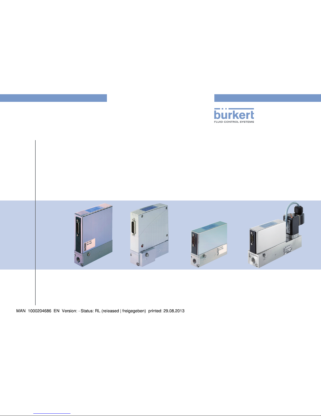
Type 8700 / 8701 / 8703 / 8705
MFM, Mass Flow Meter IP40
Type 8710 / 8711 / 8713 / 8715
MFC, Mass Flow Controller IP40
Operating Instructions
Bedienungsanleitung
Manuel d‘utilisation
Page 2

We reserve the right to make technical changes without notice.
Technische Änderungen vorbehalten.
Sous réserve de modifications techniques.
© 2013 Bürkert SAS
Operating Instructions 1307/0_EU-ML 00563582
Page 3
3
Type 8700, 8701, 8703, 8705 /
8710, 8711, 8713, 8715
1. ABOUT THIS MANUAL .................................................................................4
1.1. Symbols used ..........................................................................................4
1.2. Definition of the word "device" .......................................................4
2. INTENDED USE ................................................................................................5
3. BASIC SAFETY INFORMATION ...............................................................5
4. GENERAL INFORMATION ...........................................................................7
4.1. Manufacturer's address and international contacts ............7
4.2. Warranty conditions ..............................................................................7
4.3. Information on the Internet ...............................................................7
5. DESCRIPTION OF THE SYSTEM ............................................................7
5.1. General description ..............................................................................7
5.2. Operation of an MFM or MFC sensor ..........................................8
5.3. Detailed operation of an MFC .........................................................8
6. TECHNICAL DATA ........................................................................................11
6.1. Markings on the device.................................................................... 11
6.2. Conditions of use ................................................................................ 12
6.3. Conformity to standards and directives ..................................13
6.4. Mechanical data ................................................................................... 13
6.5. Dimensions ............................................................................................13
6.6. Fluidic data .............................................................................................18
6.7. Electrical data .......................................................................................20
7. INSTALLATION AND COMMISSIONING ...........................................22
7.1. Safety instructions ..............................................................................22
7.2. Prior to installation .............................................................................22
7.3. Description of the MFM / MFC ....................................................23
7.4. Sequence of the steps to be performed ................................ 23
7.5. Setting the parameters .................................................................... 23
7.6. Mechanical installation .....................................................................27
7.7. Fluid installation ...................................................................................27
7.8. Electrical installation .........................................................................28
8. OPERATION AND FUNCTION ................................................................30
8.1. Safety instructions .............................................................................. 30
8.2. Operation of the MFM / MFC ........................................................30
8.3. MFC operating modes ...................................................................... 35
9. MAINTENANCE, TROUBLESHOOTING ............................................ 39
9.1. Safety instructions .............................................................................. 39
9.2. Maintenance ...........................................................................................39
9.3. Troubleshooting ................................................................................... 41
10. ACCESSORIES / SPARE PARTS ......................................................44
10.1. Accessoiries ........................................................................................ 44
10.2. Spare part .............................................................................................46
11. SHUTDOWN .................................................................................................. 47
11.1. Safety instructions ........................................................................... 47
11.2. Dismounting of the MFM / MFC ............................................... 47
12. PACKAGING, STORAGE, TRANSPORT ..........................................48
12.1. Packaging, Transport ...................................................................... 48
12.2. Storage ................................................................................................... 48
13. RETURNING THE DEVICE .....................................................................48
14. DISPOSAL OF THE PRODUCT ........................................................... 49
English
Page 4
4
About this manual
Type 8700, 8701, 8703, 8705
1. ABOUT THIS MANUAL
This manual describes the entire life cycle of the device. Please keep
this manual in a safe place, accessible to all users and any new owners.
This manual contains important safety information.
Failure to comply with these instructions can lead to hazardous
situations.
• This manual must be read and understood.
1.1. Symbols used
danger
Warns against an imminent danger.
• Failure to observe this warning can result in death or in serious
injury.
Warning
Warns against a potentially dangerous situation.
• Failure to observe this warning can result in serious injury or
even death.
attention
Warns against a possible risk.
• Failure to observe this warning can result in substantial or minor
injuries.
note
Warns against material damage.
• Failure to observe this warning may result in damage to the
device or system.
Indicates additional information, advice or important
recommendations.
Refers to information contained in this manual or in other
documents.
→ Indicates a procedure to be carried out.
1.2. Definition of the word "device"
The word "device" used within this manual refers to a Mass Flow
Meter (MFM) type 8700, 8701, 8703 or 8705, or a Mass Flow
Controller (MFC) type 8710, 8711, 8713 or 8715.
English
Page 5
5
Intended use
Type 8710, 8711, 8713, 8715
2. INTENDED USE
Nonconforming use of the MFM / MFC types 8700, 8701,
8703, 8705 / 8710, 8711, 8713, 8715 may be a hazard to
people, nearby equipment and the environment.
• Mass flow meter types 8700, 8701, 8703 and 8705 are
designed exclusively for measuring the mass flow-rate of clean,
dry gases.
• Mass flow controller types 8710, 8711, 8713 and 8715 are
used for controlling the mass flow-rate of clean, dry gases.
• Only use the fluids stated on the name plate and the calibration
protocol.
• Protect this device against electromagnetic interference,
ultraviolet rays and, when installed outdoors, the effects of the
climatic conditions.
• This device must be used in compliance with the characteristics
and commissioning and use conditions specified in the
contractual documents and in the user manual.
• Requirements for the safe and proper operation of the device
are proper transport, storage and installation, as well as careful
operation and maintenance.
• Only use the device as intended.
• Observe any existing restraints when the device is exported.
3. BASIC SAFETY INFORMATION
This safety information does not take into account:
• any contingencies or occurences that may arise during installation,
use and maintenance of the devices.
• the local safety regulations for which the operating company
is responsible including the staff in charge of installation and
maintenance.
Danger from the heated surfaces when used for prolonged
periods.
• The device must be kept away from any highly flammable
materials or fluids.
• Wear protective gloves to handle the device.
Danger due to high pressure in the installation.
• Stop the circulation of fluid, cut off the pressure and drain the
pipe before loosening the process connections.
Danger due to electrical voltage.
• Shut down and isolate the electrical power source before
carrying out work on the system.
• Observe all applicable accident protection and safety
regulations for electrical equipment.
English
Page 6
6
Basic safety information
Type 8700, 8701, 8703, 8705
Danger from the outflow of operating fluid
Observe all applicable accident protection and safety regulations
for electrical equipment.
Various dangerous situations
To avoid injury take care:
• to prevent any unintentional power supply switch-on.
• to ensure that installation and maintenance work are
carried out by qualified, authorised personnel in possession of
the appropriate tools.
• to keep the device away from any highly flammable materials or
fluids and avoid any contact with bare hands,
• to guarantee a defined or controlled restarting of the process,
after a power supply or a medium supply interruption,
• to use the device only if in perfect working order and in
compliance with the instructions provided in the instruction
manual,
• to observe best industry practice for the installation and use of
these devices,
• not to use the MFM / MFC types 8700, 8701, 8703, 8705 /
8710, 8711, 8713, 8715 for controlling and/or measuring the
flow-rate of contaminated (particle size > 25 µm) or humid or
contaminated fluids,
• not to operate the device without the stainless steel mesh filter
disc installed at the factory,
• not to operate the device in a mounting position which deviates
from the calibration conditions,
• not to operate the device with higher pressures than the specified
tightness pressure (MFC) respectively calibration pressure
(MFM),
• not to subject the device to mechanical loads (e.g. by placing
objects on top of it or by using it as a step).
• not to make any external modifications to the device. Do not
paint or varnish any part of the device. Do not feed any other
fluids into the system other than the designated operating
fluid indicated on the device name plate. Exception: Agent for
cleaning and decontaminating the device (see also chap. 9.2.1).
In doing so, observe the compatibility of the materials used for
the device. A chemical compatibility chart can be found on the
Internet at:
www.burkert.com
Documentation
Brochures
Chemical
Resistance Chart
If in doubt, contact the manufacturer.
note
Elements / Components sensitive to electrostatic discharges
• This device contains electronic components sensitive to
electrostatic discharges. They may be damaged if they are
touched by an electrostatically charged person or object.
During electrostatic discharge, they will become defective
immediately or will fail when energized.
• To minimise or even avoid all damage due to an electrostatic
discharge, take all the precautions described in the EN 613405-1 and 5-2 norms.
• Also ensure that you do not touch any of the live electrical
components.
English
Page 7
7
General information
Type 8710, 8711, 8713, 8715
4. GENERAL INFORMATION
4.1. Manufacturer's address and
international contacts
To contact the manufacturer of the device, use following address:
Bürkert SAS
Rue du Giessen
F-67220 TRIEMBACH-AU VAL
The addresses of our international sales offices are available on the
internet at: www.burkert.com
4.2. Warranty conditions
The condition governing the legal warranty is the conforming use of
the MFM / MFC in observance of the operating conditions specified
in this manual.
4.3. Information on the Internet
You can find the user manuals and technical data sheets regarding the
type MFM / MFC at: www.burkert.com
5. DESCRIPTION OF THE
SYSTEM
5.1. General description
• Mass flow meter types MFM 8700, 8701, 8703 and 8705 are
devices designed for measuring the mass flow-rate of clean, dry
gases.
• Mass flow controller types MFC 8710, 8711, 8713 and 8715 are
devices designed for controlling the mass flow-rate of clean, dry
gases.
Type of the device Type of sensor
MFM 8700 Capillary/Bypass channel
8701 MEMS
8703 MEMS
8705 Capillary/Bypass channel
MFC 8710 Capillary/Bypass channel
8711 MEMS
8713 MEMS
8715 Capillary/Bypass channel
5.1.1. General operation of the Mass Flow
Meter (MFM)
The MFM integrates a sensor for measuring the flow-rate. The measured
value for the mass flow-rate is transmitted to a remote device via an
analogue or a digital output (field bus).
English
Page 8
8
Description of the system
Type 8700, 8701, 8703, 8705
5.1.2. General operation of the Mass Flow
Controller (MFC)
The MFC comprises:
• a sensor for measuring the mass flow-rate,
• control electronics,
• an actuating element: low-friction solenoid control valve with a
high response sensitivity.
5.2. Operation of an MFM or MFC
sensor
• The integrated flow-rate sensors use the thermal measurement
process (anemometric and calorimetric) to measure the mass
flow-rate. The main components are a heating resistor and a
temperature probe. The gas which passes through the device
modifies the temperature difference measured between both
resistors.
• The thermal measurement principle allows the MFC to control the
required mass flow-rate completely independently of the pressure
and temperature fluctuations in the application concerned.
The damping of the output signal can be changed with the
"Mass Flow Communicator" (see chap. 10.1.3).
On the MFC types 8710, 8711, 8713, 8715, the
technology for the integrated sensor requires filters to be
fitted upstream of the product when highly soiled fluids are
present.
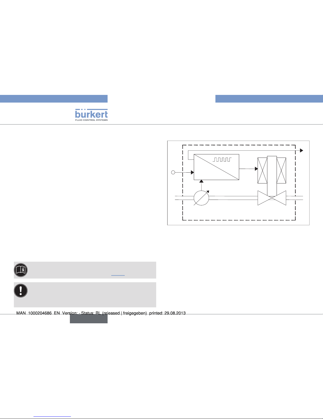
5.3. Detailed operation of an MFC
w
x
out
y
x
x
d
= w-x
Control
electronics
Sensor
Actuating element
(solenoid valve)
Gas
inlet
Gas
outlet
Fig. 1: Operating principle for the Mass Flow Controller
The control electronics compare the mass flow-rate (x) measured by
the integrated flow sensor with the mass flow-rate set-point value
(w) supplied to the MFC. The control electronics then calculate the
actuating variable (y) to be supplied to the solenoid valve to control
its opening. The flow-rate is either maintained at a constant value, or
modified to a predefined profile.
The control operates independently of fluctuations in pressure or
increases in the flow resistance which may be caused by soiling of the
filter. The rapidly responding solenoid valve and the sensor dynamics
define the overall responding time.
The measured value for the mass flow-rate is also transmitted (xout) to
a remote device via an analogue output or a digital output (field bus).
English
Page 9
9
Description of the system
Type 8710, 8711, 8713, 8715
5.3.1. Control electronics
The control electronics:
• process the mass flow-rate set-point values and measured values,
• control the solenoid valve.
Set-point value
The set-point value (w) is either transmitted either by an analogue,
normalized input signal, or digitally via the serial interface or the field bus
interface. If the set-point value is supplied by analogue transmission,
the following assignments are applied:
Signal
range
Set-point associated
with the range min.
Set-point associated
with the range max.
4...20 mA 4 mA, w = 0 % 20 mA, w = 100 %
0...20 mA 0 mA, w = 0 % 20 mA, w = 100 %
0...5 V 0 V, w = 0 % 5 V, w = 100 %
0...10 V 0 V, w = 0 % 10 V, w = 100 %
For the control of a system where quick flow-rate changes are not
permitted, a ramp function can be activated. The settings for an
ascending and a descending set-point value can be set separately.
More detailed information on the ramp function and on all
other functions can be found in the software documentation
for the MFM / MFC.
Control settings
The initial control settings are set at the factory.
• Amplification factors:
After start-up, the controller operates with amplification factors
dependent on the loop properties. When the autotune function runs,
these are determined automatically. This function enables the control
settings to be optimized for the system's actual conditions.
• Control dynamics setting:
The device has a setting which can change the control dynamics
with the aid of the "Mass Flow Communicator" software
(see chap. 10.1.3). Its extreme effects are:
1. a very quick adjustment in which overshoots are possible. This
enables the controller to respond immediately to very low control
deviations, causing the control to be very turbulent,
2. a slower adjustment to the required flow-rate. If the system is less
dynamic, the behavior of the controller may be damped so that
minor fluctuations of the measured value or set-point value are
adjusted slowly.
English
Page 10
10
Description of the system
Type 8700, 8701, 8703, 8705
Zero point shut-off
A zero point shut-off is integrated to ensure the sealing function of the
valve. This is activated if the following conditions occur at the same time:
Set-point value < 2 % of
nominal flow-rate Q
nom
(with control range 1:50)
and
Measured value < 2 % of
nominal flow-rate Q
nom
(with
control range 1:50)
If the zero point shut-off is active, the PWM signal is set to
0 % so that the valve is completely closed.
5.3.2. MFC solenoid valve
The solenoid valve used for an MFC is a direct-acting, normally closed
solenoid control valve.
The ND (nominal diameter) of the solenoid control valve is determined
by the required nominal flow-rate Q
nom
, the pressure conditions in the
process and the density of the operating fluid.
If the device is operated within the specified pressure range,
the solenoid valve also takes over the sealing function
together with the control function. Limitation: in the case
of special, hard seal materials, the seal function cannot be
ensured. In this case an additional shut-off valve may be
required.
English
Page 11
11
Technical data
Type 8710, 8711, 8713, 8715
6. TECHNICAL DATA
attention
Risk of injury from pressure and discharge of fluid.
Important device-specific technical data is indicated on the name plate and the calibration plate (see chap. 6.1).
• Observe the permitted fluid according to the name plate (depending on seal material).
• Observe the permitted pressure range on the calibration plate of the device.
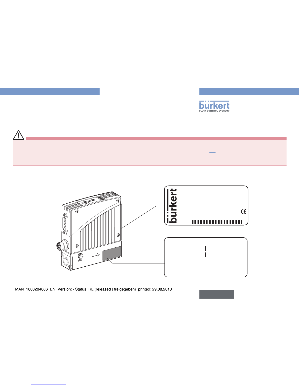
6.1. Markings on the device
Examples:
8701 20.0 Nl/min
Made in France
00210166
W49MM
24V DC 5W DP
CH4
S/N 1004
FKM
Name plate
Calibration data 00182381
QC passed: 25/11/2011
P1 : 10,00 barg
Medium 1
P1 : 10,00 barg
Medium 2
Mounting: horizontal upright
Calibration plate
Fig. 2: Name plate, calibration plate
English
Page 12
12
Technical data
Type 8700, 8701, 8703, 8705
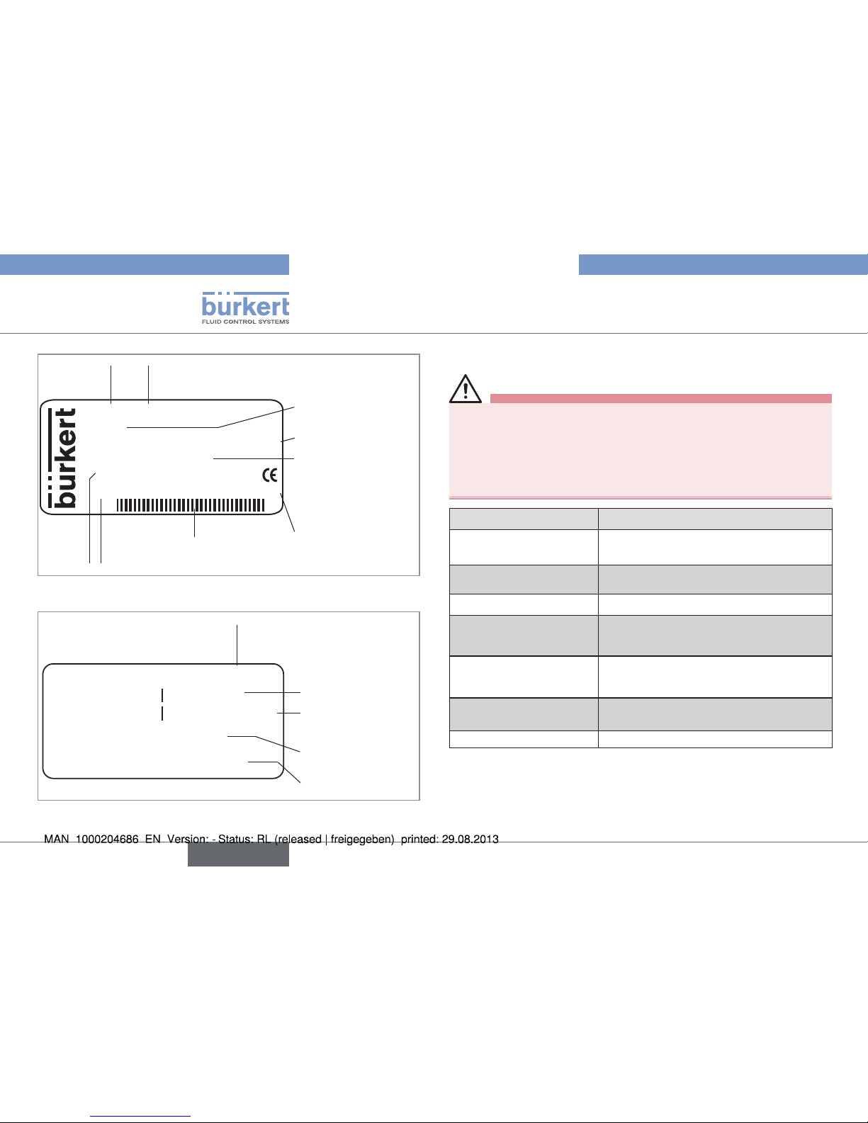
8701 20.0 Nl/min
Made in France
00210166
W49MM
24V DC 5W DP
CH4
S/N 1004
FKM
Type of
device
Operating fluid
Materail of the seal
Supply voltage
Max. power
required
Output signal
Manufacturing
code
Bar codeOrder code
of the device
Fig. 3: Detail of a name plat
Calibration date
Calibration
pressure
Mounting
position
Order code of the device
Calibration fluid
Calibration data 00182381
QC passed: 25/11/2011
P1 : 10,00 barg
Medium 1
P1 : 10,00 barg
Medium 2
Mounting: horizontal upright
Fig. 4: Details of a calibration plate
6.2. Conditions of use
Warning
Risk of injury from malfunction due to effects of weather!
The MFM / MFC is not designed for unrestricted use outdoors.
• Protect the device from direct sunlight.
• Observe the ambient temperature permitted for the device.
• Protect the device from humidity.
Setting Value
Ambient temperature -10 °C to +55 °C
For UL devices: 0 °C to 40 °C
Fluid temperature for oxygen: -10 °C to +60 °C
for the other fluids: -10 °C to +70 °C
Air humidity < 95%, without condensation
Relative humidity for UL
devices
80% up to a temperature of 31°C, with
a linear decrease to a relative humidity of
50% at 40°C
Protection rating
acc. to EN 60529
Only if devices are cabled and the
connectors are plugged in and
tightened: IP40
Absolute height above
sea level for UL devices
2000 m max.
Operating environment Indoors, with pollution degree 2
Serial
number
Nominal flow-rate (Q
nom
)
and unit flow-rate
English
Page 13
13
Technical data
Type 8710, 8711, 8713, 8715
6.3. Conformity to standards and
directives
The device conforms to the EC directives through the following standards:
• EMC: EN 61000-6-2, EN 61000-6-3
The MFM / MFC UL devices conform to the following standards:
• UL 61010-1
• CAN/CSA-C22.2 n° 61010-1.
6.4. Mechanical data
The device may be mounted in a horizontal or vertical position: see the
calibration plate and/or the calibration protocol.
Type Base block material Material of the
housing
Port
connections
8700,
8710
Stainless steel
1.4305
Polycarbonate (PC)
or sheet stainless
steel 1.4301
G 1/4, NPT
1/4, flange
8701,
8711
Stainless steel
1.4305 or aluminium
Polycarbonate (PC)
or sheet stainless
steel 1.4301
G 1/4, NPT
1/4, flange
8703,
8713
Stainless steel
1.4305 or aluminium
Sheet stainless
steel 1.4301
G 1/4, NPT
1/4, flange
8705,
8715
Stainless steel
1.4305
Sheet stainless
steel 1.4301
G 1/4, NPT
1/4, flange
Sealing material FKM, FFKM, EPDM (see name plate)
Other parts in contact with fluids, proportional valve: 1.4310, 1.4113
and 1.4305.
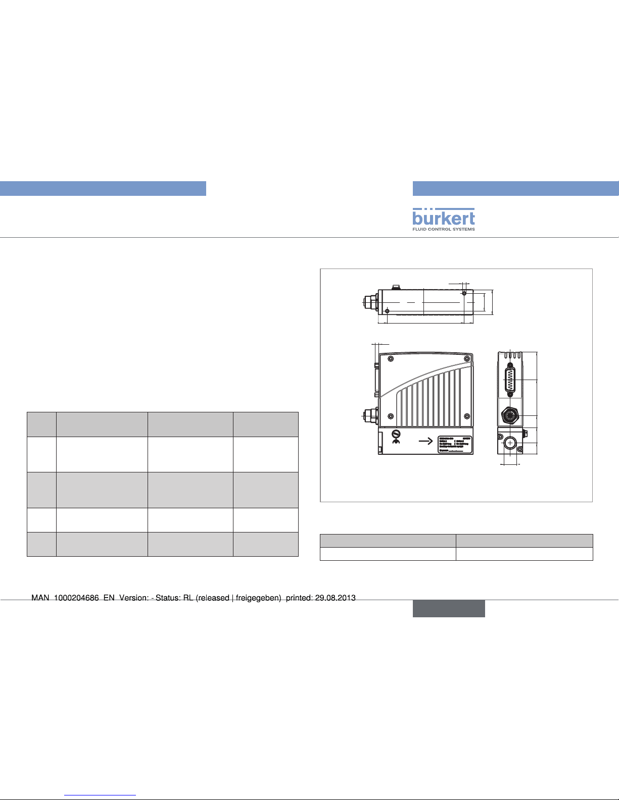
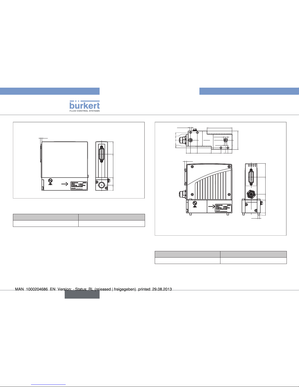
6.5. Dimensions
4,5
0
10
97
107
28
2x M4
20
0
12,5
30
43,5
84
115,5
A
Fieldbus versions:
CANopen, DeviceNet = 18
PROFIBUS DP = 16,5
Fig. 5: Dimensions of MFM types 8700 and 8701 and MFC
types 8710 and 8711
Weight aluminium (kg) Weight stainless steel (kg)
ca. 0.8 ca. 1.1
English
Page 14
14
Technical data
Type 8700, 8701, 8703, 8705
4,5
2x
Ø6
0
14
17,75
14
17,75
0
10
26
58,5
819297
107
58,5
35,5
4x
Ø 4,5
35,5
2x
Ø 8,8
43
0
5
30
43,5
84
115,5
M4
Fieldbus versions:
CANopen, DeviceNet = 18
PROFIBUS DP = 16,5
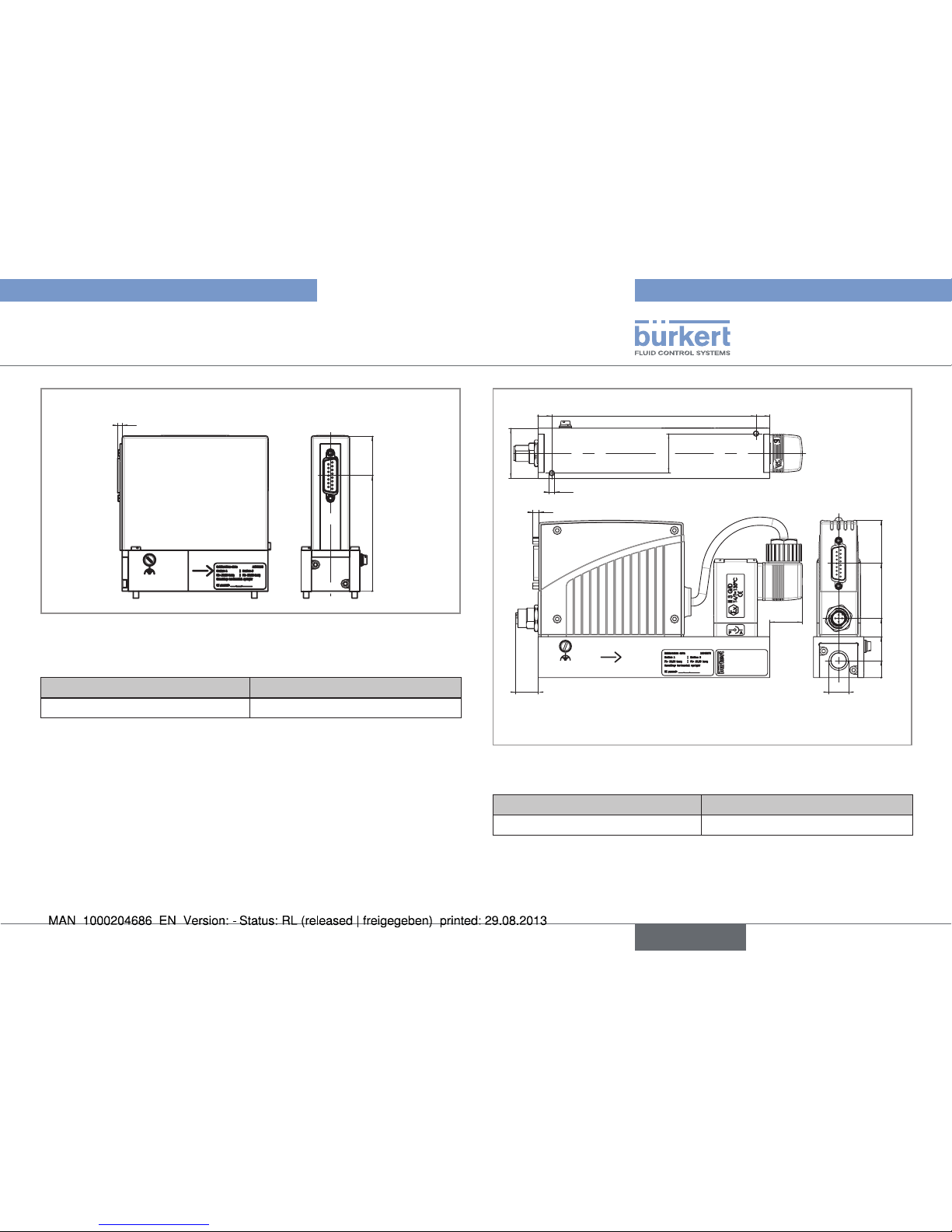
Fig. 7: Dimensions of MFM with flanges, types 8700 and 8701,
and MFC with flanges, types 8710 and 8711
Weight aluminium (kg) Weight stainless steel (kg)
ca. 0.8 ca. 1.1
3,5
0
12,5
30
85
114
Fig. 6: Dimensions of MFM with metal housing, types 8700 and
8701, and MFC with metal housing, types 8710 and 8711
Weight aluminium (kg) Weight stainless steel (kg)
ca. 0.8 ca. 1.1
English
Page 15
15
Technical data
Type 8710, 8711, 8713, 8715
3,5
0
85
114
Fig. 8: Dimensions of MFM with flanges and metal housing,
types 8700 and 8701, and MFC with flanges and metal
housing, types 8710 and 8711
Weight aluminium (kg) Weight stainless steel (kg)
ca. 0.8 ca. 1.1
4,5
24
16,5
0
12,5
30
43,5
84
115,5
A
0
10
160
170
37
29
M4
Fieldbus versions:
CANopen, DeviceNet = 18
PROFIBUS DP = 16,5
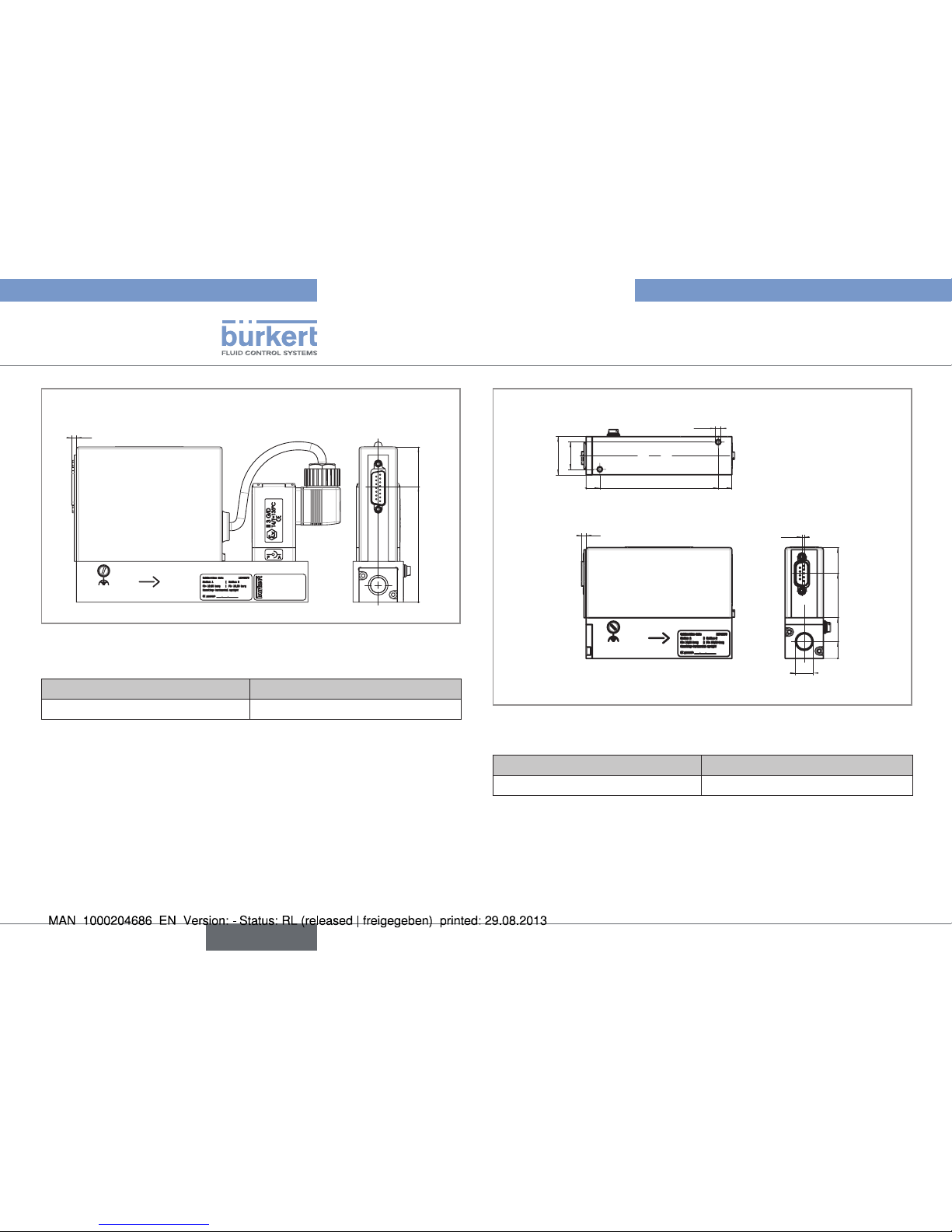
Fig. 9: Dimensions of MFC with external solenoid valve, type
8711
Weight aluminium (kg) Weight stainless steel (kg)
ca. 1.2 ca. 1.5
English
Page 16
16
Technical data
Type 8700, 8701, 8703, 8705
3,5
0
85
114
Fig. 10: Dimensions of MFC with metal housing and external
solenoid valve, type 8711
Weight aluminium (kg) Weight stainless steel (kg)
ca. 1.2 ca. 1.5
3,5
0
10
97
107
28
20
2x M4
1,7
0
12,5
30
62,5
81,5
A
Fig. 11: Dimensions of MFM types 8703 and 8705 and MFC
types 8713 and 8715
Weight aluminium (kg) Weight stainless steel (kg)
ca. 0.8 ca. 1.1
English
Page 17

17
Technical data
Type 8710, 8711, 8713, 8715
3,5
2x
Ø6
0
14
17,75
14
17,75
0
10
26
58,5
819297
107
35,5
2x
Ø 8,8
4x
Ø 4,5
35,5
43
58,5
1,7
0
5
30
62,5
81,5
2 x M4
Fig. 12: Dimensions of MFM with flanges, types 8703 and 8705,
and MFC with flanges, types 8713 and 8715
Weight aluminium (kg) Weight stainless steel (kg)
ca. 0.8 ca. 1.1
3,5
24
0
12,5
25
30
62,5
87
101,5
1,7
A
0
10
160
170
29
37
28
2x M4
Fig. 13: Dimensions of MFC with external solenoid valve, type
8713
Weight aluminium (kg) Weight stainless steel (kg)
ca. 1.2 ca. 1.5
English
Page 18

18
Technical data
Type 8700, 8701, 8703, 8705
6.6. Fluidic data
6.6.1. Overview of measurement
specifications
Device
types
Full scale range, ref.
to N2 (lN/min)
Measuring accuracy
(after heating time)
Span/control range
Settling time (MFC)
or response time
(MFM) (ms)
8700, 8710
0.01 … 15
± 1.5 % of the
measured value
± 0.3 % of the full
scale
1 : 50 < 3000
8705, 8715
8701, 8710
0.01 … 80
± 0.8 % of the
measured value
± 0.3 % of the full
scale
1 : 50 *) < 300
8703, 8713
*) Higher span (e.g. 1:100) possible on request
Repeatability: ± 0.1% of the full scale.
6.6.2. Operating fluids
• Operating fluids: clean, dry gas.
• Operating fluid for UL devices: neutral, uncontaminated gas. Other
hazardous gases are possible on request; the devices do not
release any hazardous gases under normal operating conditions.
• Calibration fluid: operating gas or air.
• Max. operating pressure: 10 bar (depending on the nominal size of
the valve).
To obtain the required measuring accuracy or control quality,
but also to respect the safety requirements, the gas or
gaseous mixture must conform to the following safety criteria,
compliant with ISO standard 8573-1 (Compressed air -
Part 1: Contaminants and purity classes):
• Particle size and maximum density: class 2:
Maximum particle size: 1 µm
1)
Maximum particle density: 1 mg/m³
1)
• Maximum dewpoint under pressure: class 4: 3°C
• Maximum oil concentration: class 1: 0.01 mg/m³
1)
1)
For more information refer to ISO 8573-1
English
Page 19

19
Technical data
Type 8710, 8711, 8713, 8715
6.6.3. Pressure loss characteristics
Q [lN/min]
∆
p [mbar]
0
10
20
30
40
50
60
70
80
90
100
110
120
130
012345678910 11 12 13 14 15
1/4''
Fig. 14: Pressure loss diagram (reference air, with a 250 µm inlet
mesh filter), types 8700 / 8705
The diagram shows exemplarily the pressure loss characteristics
when air flowing through.
For determining the pressure loss with another gas first calculate the
air equivalent of the other gas.
0
10
20
30
40
50
60
70
80
90
100
110
120
130
0510 15 20 25 30 35 40 45 50 55 60 65 70 75 80
Q [l
N
/min]
∆p [mbar]
flange
1/4''
Fig. 15: Pressure loss diagram (reference air, with a 250 µm inlet
mesh filter), types 8701 / 8703
The diagram shows exemplarily the pressure loss characteristics
when air flowing through.
Further it differentiates two designs, first one with ¼ inch connectors
and second one with connections on the bottom of the flowmeter
(used for assembly on manifolds).
For determining the pressure loss with another gas first calculate the
air equivalent of the other gas and respect the fluidics needed with
the other gas.
English
Page 20

20
Technical data
Type 8700, 8701, 8703, 8705
6.7. Electrical data
6.7.1. Electrical data for types 8703 / 8705 / 8713 / 8715
Specification Type
Power supply 24 V DC ± 10%; residual ripple < 2% (5% for UL devices)
Power supply (not provided) for UL devices Power supply limited to class 2
Type of device 8703 / 8705 8713 8715
Power required (max. in Watt) 2.5 11.5 7.5
Binary input (configurable) 1, active at the trailing edge, to be connected to DGND for activation
Communication interface RS485 supporting the MODBUS protocol
Relay output (configurable) 1, potential-free changer, 60 V, 1 A, 60 VA
LEDs (configurable) 3 LEDs, status display for Power, Communication, Error
Electrical connections Sub-D 9-pin male fixed connector
English
Page 21

21
Technical data
Type 8710, 8711, 8713, 8715
6.7.2. Electrical data for types 8700 / 8701 / 8710 / 8711
Specification Type
Power supply 24 V DC ± 10%; residual ripple < 2% (5% for UL devices)
Power supply (not provided) for UL devices Power supply limited to class 2
Type of device 8700 / 8701 8710 8711
Power required (max. in Watt) 5 10 14
MFC 8710 and 8711 only:
Analogue input (configurable)
• 0/4 - 20 mA, input impedance max.: 300 Ω, resolution : 5 µA
• 0 - 5/10 V, input impedance min. : 20 kΩ, resolution: 2.5 mV
Binary inputs (configurable) 2, active at the trailing edge, to be connected to DGND for activation
Analogue output (configurable) • 0/4 - 20 mA, max. load: 600 Ω, resolution: 20 µA
• 0 - 5/10 V, max. current: 10 mA, resolution : 10 mV
Communication interface
(alternative to analogue input + output)
PROFIBUS DP V1, DeviceNet or CANopen
Relay output (configurable) 1, potential-free changer, 60 V, 1 A, 60 VA
LEDs (configurable) 3 LEDs, status display for Power, Communication or Limit, Error
Electrical connections Sub-D 15-pin male fixed connector
Additional connections for version with field bus M12 5-pin female or male fixed connector
English
Page 22

22
Installation and commissioning
Type 8700, 8701, 8703, 8705
7. INSTALLATION AND
COMMISSIONING
7.1. Safety instructions
danger
Risk of injury due to high pressure in the installation.
• Stop the circulation of fluid, cut off the pressure and drain the
pipe before loosening the process connections.
Danger due to electrical voltage.
• Shut down and isolate the electrical power source before
carrying out work on the system.
• Observe all applicable accident protection and safety
regulations for electrical equipment.
Risk of injury from the outflow of operating fluid
• Respect the prevailing regulations on accident prevention and
safety relating to the operating fluids used.
Warning
Danger due to nonconforming installation or commissioning.
• Installation and commisioning can only be carried out by
qualified and skilled staff with the appropriate tools.
Risk of injury due to unintentional switch on of power supply
or uncontrolled restarting of the installation.
• Take appropriate measures to avoid unintentional activation of
the installation.
• Guarantee a set or controlled restarting of the process
subsequent to any intervention on the device.
7.2. Prior to installation
→ Before installing the MFM / MFC, remove dirt from the pipes and
fluid system components.
→ Connect a suitable filter (≤ 25 µm mesh size) upstream to ensure
that the operating fluid is kept clean.
note
• Use a power supply unit with adequate power.
• Observe the maximum permitted residual ripple of the operating
voltage.
English
Page 23

23
Installation and commissioning
Type 8710, 8711, 8713, 8715
7.3. Description of the MFM / MFC
LEDs
Sub-D 15-pin base Set-
point input /
Measured flow-rate
output /
Binary inputs / RS232
Screw for earth
connection
5-pin round base
24 V supply /
Relay outputs
Connection
to the line
Fig. 16: Description of the MFM / MFC
7.4. Sequence of the steps to be
performed
1. Mechanical installation
2. Fluid installation
3. Electrical installation
4. Set the device parameters
5. Pressurize the lines with operating fluid
6. Flush and completely deaerate the lines with operating fluid at
the calibration pressure
7.5. Setting the parameters
7.5.1. Setting the bus address
To ensure trouble-free setting, reset the device by switching
off the power supply to the device.
The bus address of the device can be set either via the Bürkert
configuration tool "Mass Flow Communicator" in the "Views" window
→ PROFIBUS / DeviceNet / CANopen or directly via the master bus.
The address must be reinitialized after a change on the slave and on
the master. It may be necessary, depending on the bus, to send a
corresponding telegram.
English
Page 24

24
Installation and commissioning
Type 8700, 8701, 8703, 8705
7.5.2. Setting the bus address on a device
with rotary switches for setting the
address
(type 8700 / 8701 / 8710 / 8711)
To set an address via the master bus:
→ Set the switches on an address outside the permitted
range.
→ Restart the device.
→ Set the address via the Mass Flow Communicator.
When the device is switched on, the address set with the rotary
switches is accepted as a slave address.
Valid addresses are: • PROFIBUS 0 – 126
• DeviceNet 0 – 63
• CANopen 1 – 127
If the address was set outside the permitted range, the address
setting has the validity as described in chapter 7.5.1
LSB
Unit
position
(x 1)
Unit position Digit times 1
0 – 9
0 – 9
MSB
Decade
position
(x 10)
Decade
position
Digit times
10
0 – 9
0 – 90
A
100
B
110
C
120
D
130
E
140
F
150
The address is composed of LSB + MSB
Example:
Address: MSB setting LSB setting
1 0 1
63 6 3
100 A 0
127 C 7
Fig. 17: Setting the bus address on devices with rotary switch
(types 8700 / 8701 / 8710 / 8711)
English
Page 25

25
Installation and commissioning
Type 8710, 8711, 8713, 8715
7.5.3. Pin assignment
MFM types 8700, 8701:
15-pin Sub-D plug
Pin Assignment MFM Typ 8700, 8701 Assignment MFC Typ 8710,
8711
9
10
11
12
13
14
15
1
2
3
4
5
6
7
8
1 Relay - Normally closed contact
2 Relay - Normally open contact
3 Relay - Center contact
4 GND for 24 V - Supply and binary inputs
5 24 V - Supply +
6 8 V - Output (for internal use only)
7
1)
Not used Set-point value input GND
8
1)
Not used Set-point value input +
9
2)
Measured value output GND
10
2)
Measured value output +
11 DGND (for RS232)
12 Binary input 1
13 Binary input 2
14
3)
RS232 R x D (without controller)
15
3)
RS232 T x D (without controller)
1)
In the field bus version of MFC types 8710 / 8711 these connections are not used.
2)
In the field bus version of MFC types 8710 / 8711 and MFM types 8700 / 8701 these connections are not used.
3)
To use the RS232 interface, use an adapter (item no.: see chap. 10.1.1, Electrical accessories).
English
Page 26

26
Installation and commissioning
Type 8700, 8701, 8703, 8705
MFM types 8703, 8705
and MFC types 8713, 8715:
9-pin Sub-D plug
Pin Assignment
6
7
8
9
1
2
3
4
5
1 Binary input
2 GND
3 24 V - Supply +
4 Relay - C Contact
5 Relay - NC Contact
6
1)
TX+ (RS485 - Y)
7
1)
TX- (RS485 - Z)
8
1)
RX- (RS485 - B)
9
1)
RX+ (RS485 - A)
1)
For operation in Half-Duplex mode, connect pin 6 to 9 and pin 7 to
8.
Pin assignment for field bus version
PROFIBUS DP socket, B
encoded M12 (DP V1 max. 12
MBaud)
Pin Assignment
2
1
3
4
5
1 VDD
2 R x D / T x D - N (line A)
3 DGND
4 R x D / T x D - N (line B)
5 Not used
DeviceNet or CANopen
M12 connector
Pin Assignment
1
2
4
3
5
1 Shield
2 Not used
3 DGND
4
CAN_H
5
CAN_L
English
Page 27

27
Installation and commissioning
Type 8710, 8711, 8713, 8715
7.6. Mechanical installation
Observe the mounting position shown on the calibration plate or the
calibration protocol.
7.7. Fluid installation
danger
Risk of injury due to high pressure in the installation.
• Stop the circulation of fluid, cut off the pressure and drain the
pipe before loosening the process connections.
Select the fluid connections suitable for the maximum flow-rate. There
is no minimum upstream distance to be observed.
On request, the device may be supplied with the fluid connections fitted.
Warning
Danger from leaks
If flow-rates are low and pressures high, ensure that the system
is sealed to prevent incorrect metering or the operating fluid from
leaking.
• To ensure that the seal is secure, observe the operations
described below.
Install the fittings without subjecting them to any stresses. To seal the
system properly, use fittings with olives.
Use a line with a suitable diameter and a smooth surface.
→ Cut the line squarely [1] and deburr [2].
1 2
→ In order, fit the nut [A] and the olive onto the line.
A
Olive
B
C
English
Page 28

28
Installation and commissioning
Type 8700, 8701, 8703, 8705
→ Fit the washer [C] and screw the fitting [B] to the device.
C
B
→ Insert the line and manually tighten the nut [A].
A
→ Finish tightening the nut with a suitable wrench to ensure the
mounting is sealed.
7.8. Electrical installation
danger
Risk of injury due to electrical shock
• Shut down and isolate the power supply before carrying out any
work on the system.
• Observe all applicable accident protection and safety
regulations for electrical equipment.
English
Page 29

29
Installation and commissioning
Type 8710, 8711, 8713, 8715
Warning
Risk of fire and ignition due to electrostatic discharge
If the device is electrostatically charged, highly flammable fluid
vapors may ignite if electrostatic discharge occurs.
• To avoid electrostatic charges, connect the device to the
functional earth (FE) using the shortest possible cable with the
largest possible cross section.
Danger from electromagnetic fields
If the FE connection is not connected, electromagnetic
compatibility is not assured.
• Connect the device to the functional earth (FE) via the shortest
possible cable (largest possible cross section).
note
Important information for problem-free functioning of the
device
The GND or earth connections of the MFM / MFC must always be
connected individually.
If all the GND connections are connected together and only a
single common connection fed to the control, the analogue signals
risk being subjected to fluctuations and interference.
→ Connect the functional earth (FE) to the screw indicated, for
example using an earth terminal. The connection cable must be
as short as possible and its cross section must be as large as
possible.
English
Page 30

30
Operation and function
Type 8700, 8701, 8703, 8705
8. OPERATION AND FUNCTION
8.1. Safety instructions
Warning
Risk of injury due to non-conforming operating.
Non-conforming operating could lead to injuries and damage the
device and its surroundings.
• Operating personnel must familiarize themselves with the
contents of the operating instructions.
• Observe the safety instructions and use the devices as
indicated in this manual.
• Only adequately trained personnel may operate the device.
8.2. Operation of the MFM / MFC
The MFM / MFC is operated by means of analogue standard signals
or field bus communication as well as binary inputs. Three LEDs and
a relay output are used for operation and status displays.
There is a serial interface via which a connection to a PC can be
established, using the "Mass Flow Communicator" software.
Power / Autotune
Communication
Error
LEDs
Binary
inputs /
Relay
output
Field bus
• Selecting the standard signals / Assigning the binary
inputs
The standard signal type as well as the assignment of
the binary inputs can be specified on order placement or
configured via the "Mass Flow Communicator" PC software
(see also chap. 10.1.3).
• Assigning LEDs / Assigning the relay output
The assignment of the "Communication" and "Limit(y)" LEDs
as well as the assignment of the relay outputs can also be
configured via the software
(see also chap. 10.1.3).
English
Page 31

31
Operation and function
Type 8710, 8711, 8713, 8715
8.2.1. LED default assignment
Indicator light status Possible cause
Power indicator (green) on
Power / Autotune
Limit (y)
Error
The device is energized.
Power indicator (green) flashing
Power / Autotune
Limit (y)
Error
The Autotune function is in
progress.
Communication light (yellow)
on
Power / Autotune
Communication
Error
The device is communicating
via the field bus or the serial
interface.
Indicator light status Possible cause
Limit (y) light (blue) on
Power / Autotune
Limit (y)
Error
MFM: indicates that the
measured value has almost
reached the nominal flow-rate.
MFC: indicates that the actuating
variable of the proportional valve
has almost reached 100%. In
practice this usually means that
the pressure on the controller
is not adequate to reach the
required flow-rate.
Limit (y) light (blue) flashing
Power / Autotune
Limit (y)
Error
The device is in an operating
state other than the control mode
or Autotune function.
Error light (red) on
Power / Autotune
Limit (y)
Error
Minor fault, for example the
Autotune function has failed.
Error light (red) flashing
Power / Autotune
Limit (y)
Error
Major fault, sensor damaged,
internal power supply voltage
incorrect or operating pressure
too high.
English
Page 32

32
Operation and function
Type 8700, 8701, 8703, 8705
Activation
binary input 2
Activation
binary input 1
Fig. 19: Types 8700, 8701, 8710, 8711
Input Default assignment
Binary input 1 Autotune actuation
Binary input 2 Not used
Table 1: Default assignment of binary inputs.
8.2.2. Inputs
Analogue input/output
The analogue input (MFC only) allows the set-point value, i.e. the
required flow-rate value in the line, to be received.
The analogue output enables the measured flow-rate value to be
supplied to the device to which it is connected.
Bus connection (field bus version only)
The set-point value received and the measured value are sent digitally
via the field bus. It is possible to choose between PROFIBUS DP,
DeviceNet and CANopen (see also the additional operating instructions
for field bus devices).
Binary inputs
If the binary inputs are activated, different operations can be run on the
MFC and the latter can be switched to a specific operating mode. This
is achieved by connecting the binary input to DGND for at least 0.5 s.
Activation
binary input 1
Fig. 18: Types 8703, 8705, 8713 and 8715
English
Page 33

33
Operation and function
Type 8710, 8711, 8713, 8715
Function Description
Actuate Autotune
Start of Autotune function for optimization of
the control settings to the conditions available
in the system
(see chap. 8.3).
Switch to
specification 2
The calibration curve saved under Gas 2 as
well as all settings entered there are used.
Totalizer Reset The integrated totalizer (quantity integrator) is
reset.
Start set-point
value profile
Start of the saved set-point value profile (see
chap. 8.3).
Control mode
Enables the solenoid valve to be opened at a
given value
(see chap. 8.3).
Correct safety
value*
The safety value stored in the device is used
as a flow-rate set-point value.
In this case, the flow-rate set-point value
received by the analogue input or field bus is
ignored.
Close valve
completely*
Valve completely closed.
In this case, the flow-rate set-point value is
ignored.
Open valve
completely*
Valve completely opened.
In this case, the flow-rate set-point value is
ignored.
Table 2: Possible binary input functions.
* The operating principle of the binary input (active / inactive) can
be selected for these functions
8.2.3. Relay outputs
The MFM / MFC have a relay output to indicate the operating state,
limit values outside the maximum / minimum or a fault.
Output Assignement
Relay output y2 Limit
Table 3: Relay output default assignment
Function Description
Not used No function is assigned to the relay output
Power ON The device is energized.
Autotune activated The Autotune function is in progress.
Gas 1 or 2 active Calibration curve 1 or 2 is used.
User-defined
calibration active
The device operates at the calibration
adjusted by customer.
Binary input 1 or 2
active
Binary input 1 or 2 has been activated.
Activate relay
output by field bus
The status of the relay outputs is specified via
the field bus or the serial interface.
Correct safety
value active
The safety value is used as the set-point
value.
Set-point value
profile active
The set-point value profile stored in the device
is used as the set-point value.
Control mode
active
The control mode is active, i.e. the solenoid
valve is opened at a given value.
Close valve
completely active
The close valve completely function is
activated.
English
Page 34

34
Operation and function
Type 8700, 8701, 8703, 8705
Function Description
Open valve
completely active
The open valve completely function is
activated.
Defective power
requirement
The power requirement of the device is
monitored. If this value is outside defined
limits, this function is actuated. An excessively
high or low power requirement may indicate a
defective device.
Defective internal
power supply
The operating voltage of the device is
monitored. If the defined limits exceed the
maximum or drop below the minimum, this
function is actuated.
Defective power
supply to the
sensor
The power supply voltage to the sensor is
monitored. If the defined limits exceed the
maximum or drop below the minimum, this
function is actuated.
Defective data
storage
If data storage is in the non-volatile memory of
the device, a fault has occurred.
Sensor fault The device is able to detect a defective
sensor via a self-test.
If this is the case, this function is activated.
MFI fault The field bus module (MFI) is defective
or incorrectly equipped. Field bus
communication is not possible.
x Limit The measured value has exceeded or dropped
below a limit value which can be configured.
w Limit The set-point value has exceeded or dropped
below a limit value which can be configured.
Function Description
y2 Limit The actuating variable has exceeded or
dropped below a limit value which can be
configured.
Totalisator Limit The totalizer has exceeded or dropped below
a limit value which can be configured.
Table 4: Possible relay output functions
English
Page 35

35
Operation and function
Type 8710, 8711, 8713, 8715
8.3. MFC operating modes
The MFC can adopt different operating modes:
Operating mode Status of the LEDs
(default setting)
Binary input activation mode This operating mode may be interrupted
or ended by
Standard control mode
(see chap. 8.3.1)
Power indicator (green)
on
Power / Autotune
Communication
Error
• Autotune function
• Safety function
• Set-point value profile
• Control mode
Function
Autotune
(see chap. 8.3.2)
Power indicator (green)
flashing
Power / Autotune
Communication
Error
Input active for at least 0.5 s (permanent
input activation leads to a function restart)
• Safety function
• Device reset
Safety
function
(see chap. 8.3.3)
Limit light (blue) flashing
Power / Autotune
Limit (y)
Error
As long as the input is active -
English
Page 36

36
Operation and function
Type 8700, 8701, 8703, 8705
Operating mode Status of the LEDs
(default setting)
Binary input activation mode This operating mode may be interrupted
or ended by
Set-point
value profile
(see chap. 8.3.4)
Limit light (blue) flashing
Power / Autotune
Limit (y)
Error
Input active for at least 0.5 s (permanent
input activation leads to a function restart)
• Function Autotune
• Safety function
• Device reset
Control mode
(see chap. 8.3.5)
Limit light (blue) flashing
Power / Autotune
Limit (y)
Error
As long as the input is active • Function Autotune
• Safety function
• Device reset
Table 5: Overview of the operating modes.
English
Page 37

37
Operation and function
Type 8710, 8711, 8713, 8715
8.3.1. Standard control mode
In this operating mode, the flow-rate is corrected to the specified setpoint value at a high dynamic.
The MFC is in this operating mode once energized, after a brief
initialization phase. The green power indicator is on.
The set-point value is specified via the analogue input or the field bus,
depending on the device version.
The controller settings are set in such a way that set-point value
changes or actuating variables are corrected as quickly as possible
without appreciable overshoot occurring.
The measured flow-rate value is available on the analogue output or
the field bus, depending on the device version.
For the MFC:
If the blue Limit (y) LED is on, this means that the control
signal of the proportional solenoid valve is approaching the
100% limit (see chap. 9.3).
The cause may be:
• either an insufficient pressure difference around the MFC,
for example an insufficient inlet pressure,
• or a dirty inlet filter
• This means that the set point cannot be achieved and a
difference between the set point and the measured value
(w-x) persists.
For the MFM:
If the blue Limit (y) LED is on, the measured mass flow is
approaching the nominal flow-rate or has even exceeded it
(see chap. 9.3).
If a high exceeding of the nominal flow rate occurs, a
difference between the measured and the real flow rates
may appear.
To permit an external reaction to this gap, a binary output is
activated.
8.3.2. Autotune function
The Autotune function is run through during the final
inspection in the factory, at the operating pressure and with
the calibration fluid indicated in the calibration protocol.
Therefore, the re-actuation of this function is not essential.
However, the Autotune function should be activated if:
• the pressure conditions in the system have changed
significantly,
• the calibration fluid does not correspond with the
operating fluid.
In this operating mode, the device calculates and optimizes the control
settings to the conditions present in the system.
English
Page 38

38
Operation and function
Type 8700, 8701, 8703, 8705
The proportional solenoid valve is activated according to a predefined
profile resulting in flow-rate changes. Thereby several control settings
are adjusted to the conditions on-site. These settings are stored in
the non-volatile memory of the device at the end of a successfully run
Autotune function.
This function of the MFC is obtained by activating a binary input
(configured on this function) for at least 0.5 s. The Power LED (green)
flashes to signal that the function is in progress.
Warning
Various flow-rate changes occur when the Autotune is run.
• Do not switch off the power supply to the MFC.
• Keep the supply pressure constant.
→ Before activating the Autotune function, bring the medium
pressure to a pressure close to the calibration pressure.
While the Autotune function is running, the MFC is not controlling.
When the Autotune function ends, the MFC returns to the operating
mode it was in prior to activation.
8.3.3. Safety function
In this operating mode, the device behaves as in control mode, except
that the set-point value is ignored and replaced by a predefined safety
set-point value. The default safety set-point value is 0%. This can be
modified with the "Mass Flow Communicator" PC software.
This function of the MFC is obtained by activating a binary input or via
the field bus, depending on the configuration of the device. The Limit
LED (blue) flashes to signal that the function is in progress.
8.3.4. Set-point value profile
In this operating mode, the device behaves as in standard control mode,
except that the external set-point value is ignored and replaced by a
predefined chronology of up to 30 flow-rate values (configurable with
the "Mass Flow Communicator" PC software).
This function of the MFC is obtained by activating a binary input
(configured on this function) for at least 0.5 s. The Limit LED (blue)
flashes to signal that the function is in progress.
If the set-point value profile has been activated by binary input and
the input has been reset, once the set-point value profile has been
executed, the device returns to the operating mode it was in prior to
activation.
8.3.5. Control mode
In this operating mode, the set-point value enables a duty cycle to be
directly supplied to the proportional valve, for example set-point value
10% → duty cycle of the valve = 10%.
This function of the MFC is obtained by activating a binary input or via
the field bus, depending on the configuration of the device (configurable
with the "Mass Flow Communicator" PC software). The Limit LED (blue)
flashes to signal that the function is in progress..
English
Page 39

39
Maintenance, Troubleshooting
Type 8710, 8711, 8713, 8715
9. MAINTENANCE,
TROUBLESHOOTING
9.1. Safety instructions
danger
Risk of injury due to high pressure in the installation.
• Stop the circulation of fluid, cut off the pressure and drain the
pipe before loosening the process connections.
Risk of injury due to electrical voltage.
• Shut down and isolate the electrical power source before
carrying out work on the system.
• Observe all applicable accident protection and safety
regulations for electrical equipment.
Warning
Risk of injury due to non-conforming maintenance.
• This work may only be carried out by qualified, authorized
technicians trained for working in environments where there is a
risk of explosion and using the appropriate tools.
• Ensure that the restart of the installation is controlled after any
interventions.
9.2. Maintenance
The MFM / MFC does not required any maintenance if used as indicated
in this manual. Routine recalibration is not required.
attention
Risk of injury from operating faults and device failure if the
device is opened.
Inside the device are elements to condition the flow and measure
the flow-rate. It is permitted to enter the device, for example for
cleaning, only as described in chap. 9.2.1.
Extensive device intervention causes a change to the sensor
signal, requiring recalibration at the factory.
• Do not open the device.
• Cleaning other than that described in chap. 9.2.1 and
calibration may only be performed by the manufacturer.
9.2.1. Maintenance if used with highly
soiled fluids
If highly soiled fluids are used:
→ Regularly check that the stainless steel mesh filter disc [5] is not
soiled.
→ Clean or replace it if necessary.
English
Page 40

40
Maintenance, Troubleshooting
Type 8700, 8701, 8703, 8705
4
5
7
3
2
1
6
1 - Screws
2 - Inlet flange plate
3 - O-ring
4 - O-ring
5 - Stainless steel mesh filter
6 - Orifice tube
7 - O-ring
Fig. 20: Maintenance, Cleaning
Procedure:
→ To gain access to the stainless steel mesh filter disc, detach the
input flange plate [2] (see Fig. 20).
→ Take out the stainless steel mesh filter disc.
→ Clean the stainless steel mesh filter disc [5] using distilled water
(not tap water), acetone, isopropanol or compressed air.
→ Dry the parts after cleaning.
→ Re-insert parts in the correct sequence and position
(see Fig. 20). The fine mesh of the filter disc [5] must face
the input flange plate [2].
9.2.2. Cleaning and recalibration at the
factory
If the sensor is excessively soiled or damaged by the operating gas, the
device may deviate significantly from the mass flow-rate measurement.
Cleaning or replacement followed by recalibration at the factory will
then be required.
note
• Recalibration must be carried out at the factory as it requires
the use of very precise references and a specific digital
communication system.
English
Page 41

41
Maintenance, Troubleshooting
Type 8710, 8711, 8713, 8715
9.3. Troubleshooting
Problem Possible cause Recommended action
The Power LED is off No power supply. Check the electrical connections.
The Power LED flashes
Power / Autotune
Communication
Error
The Autotune function is in progress. See chap. 8.3.
The Power LED goes out
periodically
The Power supply cuts out periodically; the device
implements a reset.
Use a power supply with adequate power.
The voltage drop in the connection cable is too high. Increase the cable cross section.
Reduce the cable length.
The Limit (y) LED comes
on
Power / Autotune
Limit (y)
Error
MFC: the solenoid valve adjustment has almost reached
100%. The set-point value has not been obtained.
Increase the operating pressure (observe the maximum
permitted supply pressure).
Check the cable resistance and reduce if required.
Check the system dimensions.
Check the filters installed in the line and clean if
required.
MFM: the measured flow-rate has almost reached or
exceeded the nominal flow-rate.
Reduce the flow-rate.
English
Page 42

42
Maintenance, Troubleshooting
Type 8700, 8701, 8703, 8705
42
Problem Possible cause Recommended action
The limit (y) LED is
flashing
Power / Autotune
Limit (y)
Error
The device is in an operating state other than standard
control mode or the Autotune function.
See chap. 8.3.
The Error LED is on
Power / Autotune
Limit (y)
Error
Minor fault, for example the last Autotune function has
failed.
Repeat Autotune
function or reset the device to acknowledge the fault.
The Error LED flashes
Power / Autotune
Limit (y)
Error
The residual ripple of the supply voltage is too high. Use a power supply with a smooth output voltage at
the required power.
A serious fault has occurred, e.g.: defective sensor or
fault in the internal power supply.
Return the device to the manufacturer to have the fault
repaired.
The sensor was operated above the permitted maximum
operating pressure.
Reduce the operating pressure.
Return the device to the manufacturer to have the fault
repaired.
No flow-rate available The set-point value is below the limit for the zero point
shut-off.
Increase the set-point value to > 2% of the nominal
flow-rate.
The device is in an operating state other than standard
control mode.
Check the operating state; see also chap. 8.3.
The lines have been sized too large or may not yet have
been completely deaerated.
Deaerate the lines.
Change the line diameter.
English
Page 43

43
Maintenance, Troubleshooting
Type 8710, 8711, 8713, 8715
43
Problem Possible cause Recommended action
The measured value
fluctuates
The earth connection (FE) is not correct. Connect the FE to the earthing point (cable as short as
possible, wire at least 2.5 mm²).
The controller must continuously correct fluctuations in
an unstable pressure supply, e.g. by pumping.
Connect a suitable pressure controller upstream.
Install a buffer tank to absorb pressure fluctuations.
The residual ripple of the supply voltage is too high. Use a power supply with a smooth output voltage at
the required power.
Set-point value at 0%,
but the fluid is circulating
The operating pressure is above the operating pressure
maintained by the proportional valve.
Reduce the operating pressure.
Return the device to the manufacturer to have the fault
repaired.
Set-point value = 0%,
valve is closed, no
flow-rate in the line;
but the measured
flow-rate is not zero
The mounting position of the device is incorrect. Install the MFC in the mounting position shown in the
calibration protocol or the calibration plate and run an
Autotune function to adjust to the operating conditions.
A fluid other than that designated by the calibration is
used.
Return device to the manufacturer for recalibration for
the operating fluid.
Set-point value is not
reached
The filter is blocked. Clean or replace the filter.
The primary pressure is too low. Increase primary pressure to calibration pressure.
The back pressure is too high. Check components for soiling downstream of the
device and if required clean.
English
Page 44

44
Accessories / Spare parts
Type 8700, 8701, 8703, 8705
10. ACCESSORIES / SPARE
PARTS
attention
Risk of injury and/or damage caused by the use of unsuitable
parts.
Incorrect accessories and unsuitable replacement parts may
cause injuries and damage the device and the surrounding area.
• Use only original accessories from Bürkert..
10.1. Accessoiries
The Bürkert accessories indicated below are recommended for
problem-free operation, maintenance and repair of the device.
10.1.1. Electrical accessories
Types Item Order code
8700, 8701,
8710, 8711
SUB-D 15-pin plug
(to be soldered)
918 274
Cover for SUB-D
15-pin plug
918 408
Sub-D 15-pin plug with 5 m cable,
with stripped end
787 737
Sub-D 15-pin plug with 10 m
cable, with stripped end
787 738
RS232 adapter for connection to a PC654 748
Extension cable for Sub-D 9-pin
plug, RS232, 2 m
917 039
RS422 adapter 666 371
USB adapter 670 639
Configuration software
(Mass Flow Communicator)
Can be
downloaded at
www.burkert.
com
Profibus
versions of
types 8700,
8701, 8710
and 8711
Straight M12 plug (code B) 918 198
Straight M12 socket (coupling)
(code B)
918 447
PROFIBUS* Y-piece 902 098
PROFIBUS terminal resistor
(code B)
902 553
English
Page 45

45
Accessories / Spare parts
Type 8710, 8711, 8713, 8715
Types Item Order code
Profibus
versions of
types 8700,
8701, 8710
and 8711
GSD sheet Download from
www.burkert.
com
DeviceNet,
CANopen
version of
types 8700,
8701, 8710
and 8711
Straight M12 plug (code A) 917 115
Straight M12 socket (coupling)
(code A)
917 116
DVN/CAN* Y-piece 788 643
DVN/CAN terminal resistor
(code A)
On request
EDS sheet for DeviceNet Download from
www.burkert.
com
8703, 8705,
8713, 8715
SUB-D 9-pin base
(to be soldered)
917 623
RS232 adapter for connection to
a PC
667 530
Extension cable for Sub-D 9-pin
plug, RS232, 2 m
917 039
USB adapter 670 693
Sub-D 9-pin adapter with
2 terminal blocks (for 2 connection
cables)
919 465
* The two previous M12 connectors cannot be used together on the same
side of the Y-junction. At least one of the two M12 connectors must be a
prefabricated cable with a thinner connector.
10.1.2. Fluid accessories
The MFM / MFC are equipped with a connection plate which uses
a DIN ISO 228/1 thread process connection.
A threaded fitting available as an accessory is used to connect
the device to a line:
• the connection to the device side has a DIN ISO 228/1 thread,
• the connection to the line side is available in a range of
dimensions.
A sealing ring must be ordered for each screw fitting!
Connection
to the device,
with DIN ISO
228/1 thread
Diameter of
the line
Material Order code Order code,
sealing ring
G 1/4 6 mm
Stainless
steel
901 538 901 575
G 1/4 8 mm 901 540 901 575
G 1/4 1/4 " 901 551 901 579
G 1/4 3/8 " 901 553 901 579
Other accessories for the fluid connection of an
MFM / MFC can be found under Type 1013 in the Bürkert
accessories catalog.
English
Page 46

46
Accessories / Spare parts
Type 8700, 8701, 8703, 8705
10.1.4. Additional documentation
Item Order code
Supplement to the operating instructions for field
bus devices
804 553
Contamination Declaration 806 075
"Configuration via PROFIBUS with GDS file"
addendum
805 923
10.2. Spare part
Item Order code
Stainless steel mesh filter, mesh size 250 µm, for
8700, 8701, 8703 / 8710, 8711, 8713
654 733
Stainless steel mesh filter, mesh size 25 µm,
for 8700 / 8710, 8711, 8713
676 329
10.1.3. Mass Flow Communicator
(PC software)
The "Mass Flow Communicator" PC software designed for
communication with the devices from the Mass Flow Controller and
Liquid Flow Controller families supplied by Bürkert.
The software runs on the Windows platform and
communicates with the MFM / MFC via a serial interface.
This software enables:
• information specific to the device to be read,
• the assignment of binary inputs and outputs to be changed,
• the assignment of LEDs to be changed,
• various functions to be activated,
• certain dynamic properties to be modified,
• a user specific calibration to be performed,
• the firmware to be updated,
• ...
English
Page 47

47
Shutdown
Type 8710, 8711, 8713, 8715
11. SHUTDOWN
11.1. Safety instructions
danger
Danger due to high pressure in the installation.
• Stop the circulation of fluid, cut off the pressure and drain the
pipe before loosening the process connections.
Danger from the outflow of operating fluid.
• Respect the prevailing regulations on accident prevention and
safety relating to the operating fluids used.
Danger due to electrical voltage.
• Shut down and isolate the electrical power source before
carrying out work on the system.
• Observe all applicable accident protection and safety
regulations for electrical equipment.
Warning
Risk of injury from nonconforming dismounting.
• Maintenance must only be carried out by qualified and skilled
staff with the appropriate tools.
11.2. Dismounting of the MFM / MFC
Procedure:
B
A
C
→ Relieve the operating medium pressure in the system.
→ Clean the device using a neutral fluid (nitrogen, for example).
→ Relieve the rinsing medium pressure in the system.
→ Switch off the power supply [A].
→ Disconnect the electrical connections [B].
→ Disconnect the fluid connections [C].
→ Remove the MFM / MFC.
English
Page 48

48
Packaging, Storage, Transport
Type 8700, 8701, 8703, 8705
12. PACKAGING, STORAGE,
TRANSPORT
12.1. Packaging, Transport
note
Damage due to transport
Inadequately protected equipment may be damaged during
transport.
• Remove all cables, connections, separate filters and installation
material.
• Clean and air contaminated devices.
• Protect fluid connections from damage by fitting protective caps
and seal.
• Pack the device in two suitable bags, sealed with protective film.
• During transportation protect the device against humidity and
dirt in shock-resistant packaging.
• Do not expose the device to temperatures outside the storage
temperature range.
12.2. Storage
note
Poor storage can damage the device.
• Store the device in a dry place away from dust.
• Storage temperature: -10 °C to +70 °C.
13. RETURNING THE DEVICE
No work or tests will be carried out on the device until
there is a valid Contamination Declaration.
The Contamination Declaration can be downloaded from our
Homepage or requested from your local after-sales service.
www.buerkert.fr
Service
Servicing/Maintenance/
Commissioning
Contamination Declaration
To return a device already in use, a returns number is
required.
If you would like to return a device already in use to Bürkert, proceed
as follows:
→ Complete the Contamination Declaration.
→ Send the declaration to the address indicated on the form:
Bürkert will fax or e-mail you a returns number.
→ Pack the device in consideration of the information in chap. 12.1.
→ Return the device to Bürkert with the Contamination Declaration,
quoting this returns number.
Adress:
Bürkert Fluid Control Systems
Corporate Quality / Complaint Management
Chr.-Bürkert-Str. 13-17
D-74653 Ingelfingen
Tél. + 49 (0) 7940 - 10 91 599
Fax + 49 (0) 7940 - 10 91 490
E-mail: service.international@burkert.com
English
Page 49

49
Disposal of the product
Type 8710, 8711, 8713, 8715
14. DISPOSAL OF THE PRODUCT
→
Sort used products according to their type.
→ Dispose of the device and its packaging in an environmentally-
friendly way.
note
Damage to the environment caused by products
contaminated by fluids.
• Keep to the existing provisions on the subject of waste disposal
and environmental protection.
Comply with the national and/or local regulations which
concern the area of waste disposal.
English
Page 50

50
Type 8700, 8701, 8703, 8705
English
Page 51

Page 52

www.burkert.com
 Loading...