

Page 1
Type 8692, 8693
Positioner TopControl
Process Controller TopControl
Electropneumatic positioner
Electropneumatic process controller
Operating Instructions
Bedienungsanleitung
Manuel d‘ utilisation
Page 2

We reserve the right to make technical changes without notice.
Technische Änderungen vorbehalten.
Sous réserve de modifications techniques.
© 2008-2011 Bürkert Werke GmbH
Operating Instructions 1111/01_EU-ML_00806169 / Original DE
Page 3

Type 8692, 8693
Table of contents
Positioner Type 8692, 8693
Table of ConTenTs
GENERAL INFORMATION AND SAFETY INSTRUCTIONS ....................................................................................................7
1. Operating instructions .........................................................................................................................................................8
2. Authorized use ........................................................................................................................................................................9
3. Basic safety instructions .................................................................................................................................................10
4. General Information...........................................................................................................................................................11
DESCRIPTION OF SYSTEM ...................................................................................................................................................................13
5. Function of the positioner and combination with valve types ....................................................................14
6. Structure of the positioner ............................................................................................................................................17
7. Type 8692 positioner with position controller .....................................................................................................20
8. Type 8693 positioner with process controller .....................................................................................................24
9. Interfaces of the positioner for the multipole model ......................................................................................28
10. Interfaces of the positioner for the models with cable gland ....................................................................29
11. Technical Data ......................................................................................................................................................................30
CONTROL AND DISPLAY ELEMENTS, OPERATING MODES ...........................................................................................35
12. Control and display elements ......................................................................................................................................36
13. Operating modes ................................................................................................................................................................39
14. Operating Levels .................................................................................................................................................................43
INSTALLATION ...............................................................................................................................................................................................45
15. Installation ..............................................................................................................................................................................47
16. Fluid connection ..................................................................................................................................................................57
17. Electrical Connection 24 V DC with circular plug-in connector (multi-pole model) .......................59
18. Electrical Connection 24 V DC with Cable Gland ..............................................................................................67
19. Initial start-up ........................................................................................................................................................................ 72
english
3
Page 4
Type 8692, 8693
Table of contents
START-UP AND OPERATION OF THE POSITION CONTROLLER TYPE 8692 .........................................................77
20. Starting up and installing the position controller Type 8692 ......................................................................79
21. Operation of the position controller .........................................................................................................................87
22. Configuring the auxiliary functions ...........................................................................................................................92
START-UP AND OPERATION OF THE POSITION CONTROLLER TYPE 8693 ...................................................... 125
23. Starting up and setting up the process controller Type 8693 ................................................................. 127
24. Operation of the process controller ......................................................................................................................149
25. Auxiliary functions for the process controller ..................................................................................................154
PROFIBUS-DP ............................................................................................................................................................................................. 173
26. General Information........................................................................................................................................................174
27. Technical Data ................................................................................................................................................................... 174
28. Safety Settings if the Bus Fails ................................................................................................................................ 175
29. Interfaces .............................................................................................................................................................................175
30. Electrical connections ...................................................................................................................................................176
31. Settings on the positioner ........................................................................................................................................... 179
32. Functional Deviations from the Standard Model ............................................................................................ 184
33. Configuration in the Profibus-DP Master ............................................................................................................ 184
34. Bus Status Display .......................................................................................................................................................... 187
35. Configuration with Siemens Step7 ........................................................................................................................ 188
DEVICENET ................................................................................................................................................................................................... 191
36. General Information........................................................................................................................................................193
37. Definition of Terms ..........................................................................................................................................................193
38. Technical Data ................................................................................................................................................................... 194
39. Safety Settings if the Bus Fails ................................................................................................................................ 195
40. Interfaces ............................................................................................................................................................................. 195
41. Electrical connections ...................................................................................................................................................196
42. Settings on the positioner in the Main Menu .................................................................................................... 200
43. Functional Deviations from the Standard Model ............................................................................................ 203
44. Configuration of the Process Data ......................................................................................................................... 204
4
english
Page 5
Type 8692, 8693
Table of contents
45. Bus Status Display .......................................................................................................................................................... 207
46. Configuration Example 1 ............................................................................................................................................. 208
47. Configuration Example 2 ............................................................................................................................................. 211
MAINTENANCE AND TROUBLESHOOTING ..............................................................................................................................213
48. Maintenance ....................................................................................................................................................................... 214
49. Error messages and malfunctions Type 8692 .................................................................................................. 216
50. Error messages and malfunctions Type 8693 .................................................................................................. 218
DISASSEMBLY ............................................................................................................................................................................................ 223
51. Disassembly ....................................................................................................................................................................... 224
PACKAGING, STORAGE AND DISPOSAL ..................................................................................................................................227
52. Packaging and transport .............................................................................................................................................. 228
53. Storage .................................................................................................................................................................................. 228
54. Disposal ................................................................................................................................................................................ 228
ACCESSORIES............................................................................................................................................................................................229
55. Accessories ......................................................................................................................................................................... 230
GENERAL RULES (APPENDIX).........................................................................................................................................................231
56. Selection criteria for continuous valves .............................................................................................................. 232
57. Properties of PID controllers ..................................................................................................................................... 234
58. Adjustment rules for PID controllers ..................................................................................................................... 240
OPERATING STRUCTURE OF THE POSITIONER (APPENDIX) ....................................................................................245
59. Operating Structure ........................................................................................................................................................ 246
TABLES FOR CUSTOMER-SPECIFIC SETTINGS (APPENDIX) ....................................................................................253
60. Settings of the freely programmable characteristic Type 8692 and Type 8693 ............................254
61. Set parameters of the process controller Type 8693 ...................................................................................255
MASTERCODE (APPENDIX) ............................................................................................................................................................. 257
62. Mastercode .......................................................................................................................................................................... 258
english
5
Page 6

Type 8692, 8693
Table of contents
6
english
Page 7

Type 8692, 8693
General information and safety instructions
Table of ConTenTs
1. OPERATING INSTRUCTIONS ........................................................................................................................................................8
1.1. Symbols ......................................................................................................................................................................................8
2. AUTHORIZED USE .............................................................................................................................................................................9
2.1. Restrictions ...............................................................................................................................................................................9
3. BASIC SAFETY INSTRUCTIONS ..............................................................................................................................................10
4. GENERAL INFORMATION .............................................................................................................................................................11
4.1. Contact address ..................................................................................................................................................................11
4.2. Warranty ...................................................................................................................................................................................11
4.3. Master code ...........................................................................................................................................................................11
4.4. Information on the internet ............................................................................................................................................11
english
7
Page 8
Type 8692, 8693
General Information
Safety Instructions
1. OPERATING INSTRUCTIONS
The operating instructions describe the entire life cycle of the device. Keep these instructions in a location which is
easily accessible to every user and make these instructions available to every new owner of the device.
WARNING!
The operating instructions contain important safety information!
Failure to observe these instructions may result in hazardous situations.
• The operating instructions must be read and understood.
1.1. Symbols
DANGER!
Warns of an immediate danger!
• Failure to observe the warning may result in a fatal or serious injury.
WARNING!
Warns of a potentially dangerous situation!
• Failure to observe the warning may result in serious injuries or death.
CAUTION!
Warns of a possible danger!
• Failure to observe this warning may result in a moderately severe or minor injury.
NOTE!
Warns of damage to property!
• Failure to observe the warning may result in damage to the device or the equipment.
Indicates important additional information, tips and recommendations.
refers to information in these operating instructions or in other documentation.
designates a procedure which you must carry out.
8
english
Page 9
Type 8692, 8693
General Information
Safety Instructions
2. AUTHORIZED USE
Incorrect use of the positioner Type 8692 and Type 8693 may be a hazard to people, nearby equipment
and the environment.
The device is designed to be mounted on pneumatic actuators of process valves for the control of media.
• Do not expose the device to direct sunlight.
• Use according to the permitted data, operating conditions and conditions of use specified in the contract
documents and operating instructions, as described in chapter “Description of system” - “11. Technical
data“ in this manual and in the valve manual for the respective pneumatically actuated valve.
• The device may be used only in conjunction with third-party devices and components recommended and
authorised by Bürkert.
• In view of the large number of options for use, it is essential prior to installation to study and, if necessary, to
test whether the positioner is suitable for the specific application case.
• Correct transportation, correct storage and installation and careful use and maintenance are essential for
reliable and problem-free operation.
• Use the positioner Type 8692 and Type 8693 only as intended.
2.1. Restrictions
If exporting the system/device, observe any existing restrictions.
english
9
Page 10
Type 8692, 8693
General Information
Safety Instructions
3. BASIC SAFETY INSTRUCTIONS
These safety instructions do not make allowance for any
• contingencies and events which may arise during the installation, operation and maintenance of the devices.
• local safety regulations; the operator is responsible for observing these regulations, also with reference to the
installation personnel.
DANGER!
Danger – high pressure!
• Before loosening the lines and valves, turn off the pressure and vent the lines.
Risk of electric shock!
• Before reaching into the device or the equipment, switch off the power supply and secure to prevent
reactivation!
• Observe applicable accident prevention and safety regulations for electrical equipment!
General hazardous situations.
To prevent injury, ensure that:
• the system cannot be activated unintentionally.
• Installation and repair work may be carried out by authorised technicians only and with the appropriate tools.
• After an interruption in the power supply or pneumatic supply, ensure that the process is restarted in a defined
or controlled manner.
• The device may be operated only when in perfect condition and in consideration of the operating instructions.
• The general rules of technology apply to application planning and operation of the device.
• Do not put any loads on the body (e.g. by placing objects on it or standing on it).
• Do not make any external modifications to the device bodies. Do not paint the body parts or screws.
NOTE!
Electrostatic sensitive components / modules!
• The device contains electronic components which react sensitively to electrostatic discharge (ESD). Contact
with electrostatically charged persons or objects is hazardous to these components. In the worst case scenario,
they will be destroyed immediately or will fail after start-up.
10
• Observe the requirements in accordance with EN 100 015 - 1 and 5 - 2 to minimise or avoid the possibility of
damage caused by sudden electrostatic discharge!
• Also ensure that you do not touch electronic components when the power supply voltage is present!
The positioners Type 8692 and Type 8693 were developed with due consideration given to the accepted
safety rules and is state-of-the-art. However, dangers can still arise.
Failure to observe this operating manual and its operating instructions as well as unauthorized tampering with
the device release us from any liability and also invalidate the warranty covering the devices and accessories!
english
Page 11

Type 8692, 8693
General Information
Safety Instructions
4. GENERAL INFORMATION
4.1. Contact address
Germany
Bürkert Fluid Control System
Sales Center
Chr.-Bürkert-Str. 13-17
D-74653 Ingelfingen
Tel. + 49 (0) 7940 - 10 91 111
Fax + 49 (0) 7940 - 10 91 448
E-mail: info@de.buerkert.com
International
Contact addresses can be found on the final pages of the printed operating instructions.
And also on the Internet at:
www.burkert.com
4.2. Warranty
The warranty is only valid if the positioner Type 8692 and Type 8693 is used as intended in accordance with the
specified application conditions.
4.3. Master code
Operation of the device can be locked via a freely selectable user code. In addition, there is a non-changeable master
code with which you can perform all operator control actions on the device. This 4-digit master code can be found
in the Appendix of these operating instructions in the chapter entitled “Master code”.
If required, cut out the code and keep it separate from these operating instructions.
4.4. Information on the internet
The operating instructions and data sheets for Type 8694 can be found on the Internet at:
www.burkert.com
english
11
Page 12

Type 8692, 8693
General Information
Safety Instructions
12
english
Page 13
Type 8692, 8693
Description of system
Table of ConTens
5. FUNCTION OF THE POSITIONER AND COMBINATION WITH VALVE TYPES .................................................14
5.1. Models of the positioner .................................................................................................................................................15
5.2. Features of the valve types ...........................................................................................................................................16
6. STRUCTURE OF THE POSITIONER .......................................................................................................................................17
6.1. Representation .....................................................................................................................................................................17
6.2. Features ...................................................................................................................................................................................18
6.3. Function diagram of the positioner with single-acting actuator ...............................................................19
7. TYPE 8692 POSITIONER WITH POSITION CONTROLLER .........................................................................................20
7.1. Schematic representation of the positioner Type 8692 .................................................................................21
7.2. Properties of the position controller software ....................................................................................................22
8. TYPE 8693 POSITIONER WITH PROCESS CONTROLLER .........................................................................................24
8.1. Schematic representation of the process control ............................................................................................25
8.2. Functions of the process controller software .....................................................................................................26
9. INTERFACES OF THE POSITIONER FOR THE MULTIPOLE MODEL ....................................................................28
10. INTERFACES OF THE POSITIONER FOR THE MODELS WITH CABLE GLAND .............................................29
11. TECHNICAL DATA .............................................................................................................................................................................30
11.1. Safety positions after failure of the electrical or pneumatic auxiliary power .....................................30
11.2. Factory settings of the positioner ..............................................................................................................................31
11.3. Specifications of the positioner ..................................................................................................................................32
11.3.1. Conformity .................................................................................................................................................32
11.3.2. Standards ..................................................................................................................................................32
11.3.3. Operating conditions .............................................................................................................................. 32
11.3.4. Mechanical data ....................................................................................................................................... 32
11.3.5. Electrical data ...........................................................................................................................................32
11.3.6. Pneumatic Data .......................................................................................................................................33
11.3.7. Type label ..................................................................................................................................................34
english
13
Page 14
Type 8692, 8693
Description of system
5. FUNCTION OF THE POSITIONER AND
COMBINATION WITH VALVE TYPES
Positioners Type 8692 and Type 8693 are electropneumatic positioner for pneumatically actuated control valves
with single-acting or double-acting actuators.
Together with the pneumatic actuator the positioner forms an optical and functional unit.
The control valve systems can be used for a wide range of control tasks in fluid technology and, depending on the
application conditions, different process valves belonging to series 2300 or 2103 from the Bürkert range can be
combined with the positioner. Angle-seat valves, diaphragm valves or ball valves fitted with a control cone are suitable.
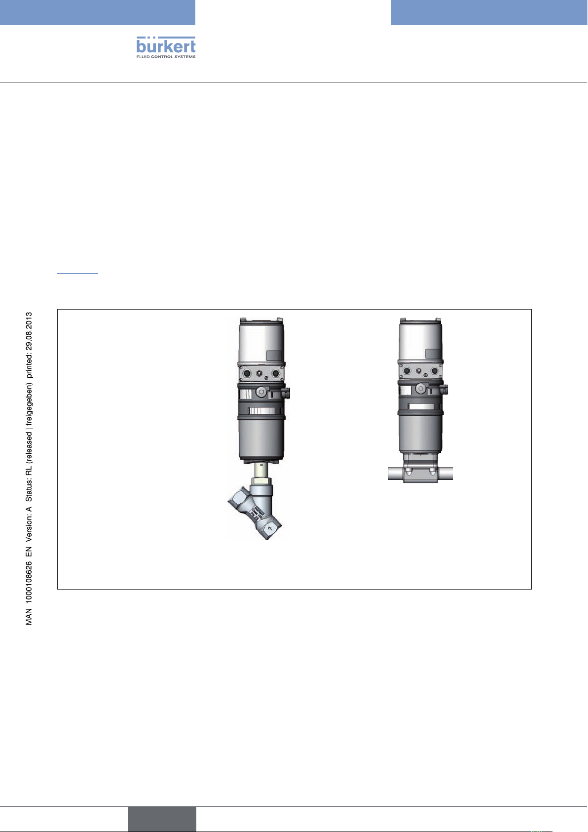
“Figure 1” shows an overview of the possible combinations of positioner and different pneumatically actuated valves.
Different actuator sizes and valve nominal widths, not illustrated here, are available for each type. More precise
specifications can be found on the respective data sheets. The product range is being continuously expanded.
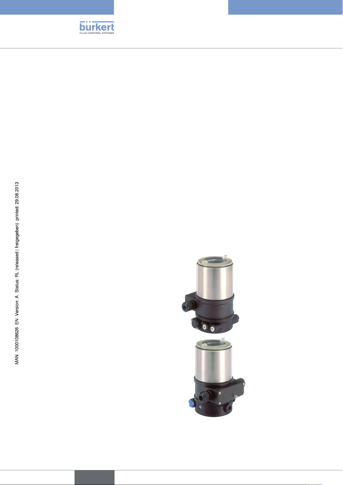
Positioner
Type 8692
Type 8693
with slanted seat valve
Type 2300
Figure 1: Overview of possible combinations
with diaphragm valve
Type 2103
14
english
Page 15

Type 8692, 8693
Description of system,
5.1. Models of the positioner
The positioner is available in 2 versions:
Type 8692 - Positioner with positioning control
The position of the actuator (stroke) is regulated according to the position set-point value. The position set-point
value is specified by an external uniform signal (or via field bus).
Type 8693 - Positioner with process control
The positioner is linked to a control circuit. The position set-point value of the valve is calculated from the process
set-point value and the actual process value via the control parameters (PID controller). The process set-point value
can be set by an external signal.
Pneumatically actuated piston actuators and rotary actuators can be used as a actuator. Both single-acting and
double-acting actuators are offered in combination with the positioner.
For single-acting actuators, only one chamber is aerated and deaerated during actuation. The generated pressure
works against a spring. The piston moves until there is an equilibrium of forces between compressive force and
spring force.
For double-acting actuators the chambers on both sides of the piston are pressurised. In this case, one chamber is
aerated when the other one is deaerated and vice versa. In this design, no spring is installed in the actuator.
english
15
Page 16
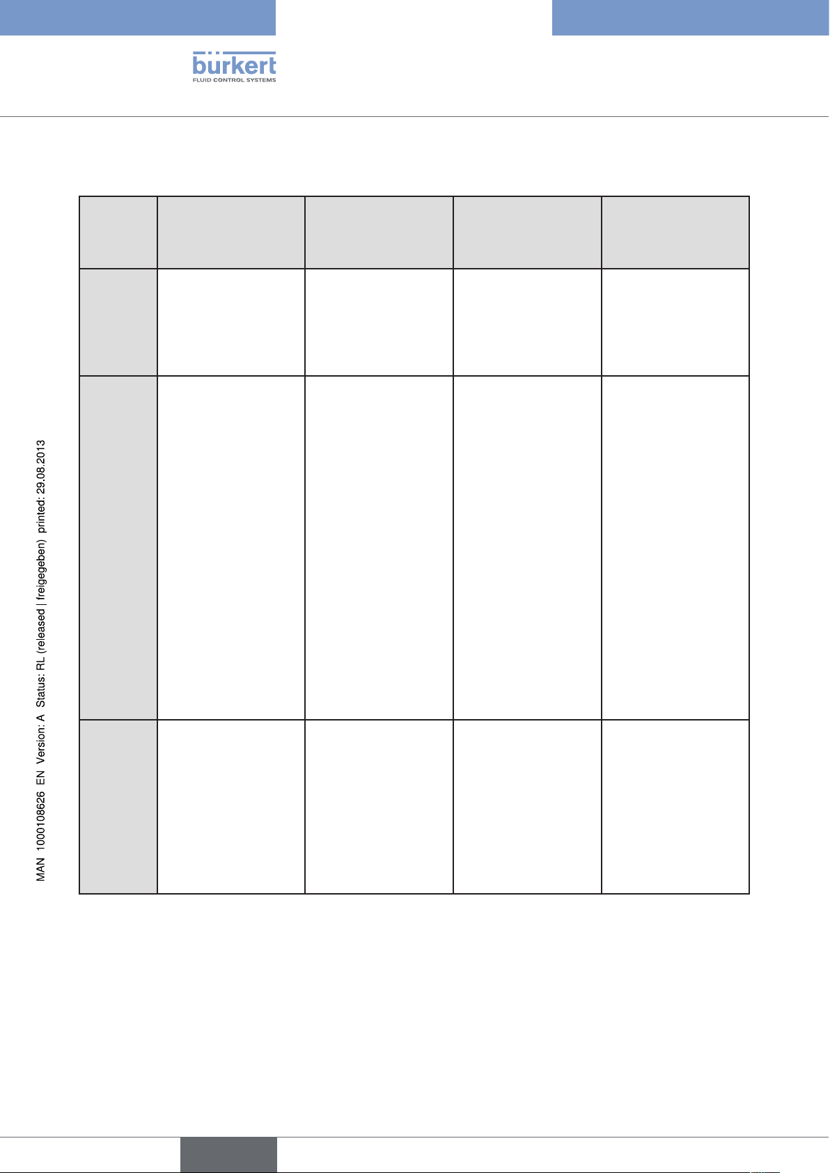
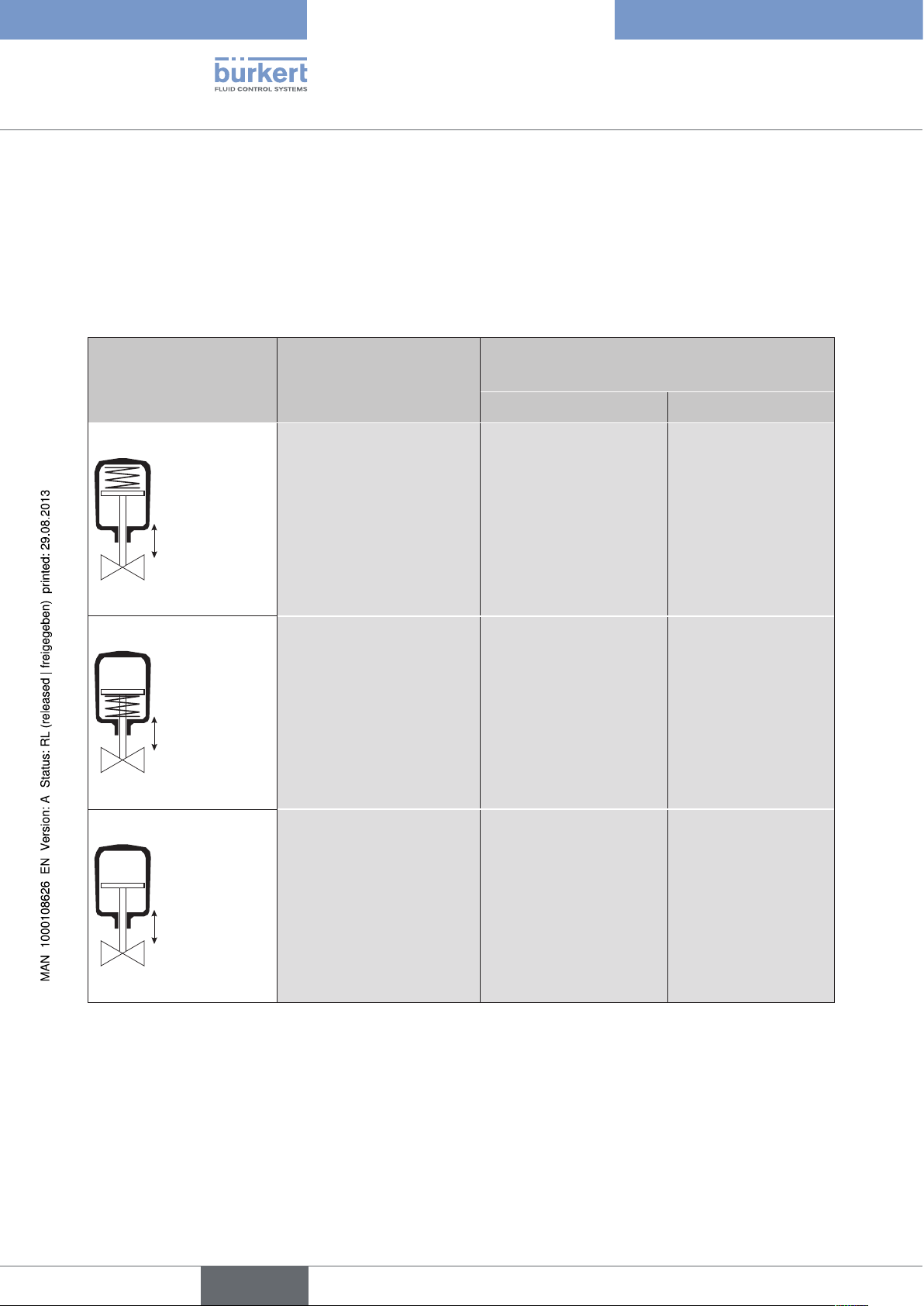
5.2. Features of the valve types
Type 8692, 8693
Description of system
Types
Features
Slanted seat control
valves / screw-down
stop globe control
valves
• 2702
• 2712
• 2300
• 2301
• incoming flow under
seat
• closes smoothly
• straight flow path of
the medium
• self-adjusting
stuffing box for high
leak-tightness
Diaphragm valves Ball valves Flap valves
• 2730
• 2103
• 2731
• medium is hermetically separated from
the actuator and
environment
• cavity-free and selfdraining body design
• any flow direction
with low-turbulence
flow
• steam-sterilizable
• CIP-compliant
• closes smoothly
• 2652
• 2655
• 2658
• scrapable
• minimum dead
space
• unaffected by
contamination
• little pressure loss
compared to other
valve types
• seat and seal can
be exchanged in the
three-piece ball valve
when installed
• 2672
• 2675
• unaffected by
contamination
• little pressure loss
compared to other
valve types
• inexpensive
• low construction
volume
Typical
media
Table 1: Features of the valve types
• water, steam and
gases
• alcohols, oils, propellants, hydraulic
fluids
• salt solutions, lyes
(organic)
• solvents
• actuator and diaphragm can be
removed when the
body is installed
• neutral gases and
liquids
• contaminated,
abrasive and
aggressive media
• media of higher
viscosity
Information
Can be used as
process controller only
• neutral gases and
liquids
• clean water
• slightly aggressive
media
• neutral gases and
liquids
• slightly aggressive
media
16
english
Page 17
Type 8692, 8693
Description of system,
6. STRUCTURE OF THE POSITIONER
The positioners Type 8692 and Type 8693 consist of the micro-processor controlled electronics, the position measuring system and the control system.
The appliance is designed using three-wire technology. Operation of the positioner is controlled by four keys and a
128x64 dot matrix graphic display.
The pneumatic control system for single or double-acting actuators consists of two or four solenoid valves.
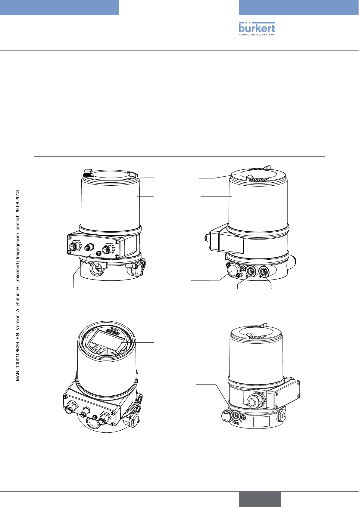
6.1. Representation
Transparent cap
Body casing
Electrical connection module
(here with circular plug-in connectors)
Pressure limiting valve
(for protection against too
high internal pressure in
case of error)
Exhaust air connection
(label: 3)
Control module with
display and keys
(View without transparent cap)
Additional
Exhaust air connection
(connection: 3.1)
only with Type 23xx
and 2103
with pilot-operated
control system for high
air output (actuator size
ø 125 / 130)
Pilot air port
(label: 1)
Figure 2: Structure
17
english
Page 18
Type 8692, 8693
Description of system
6.2. Features
• Models
for single-acting or double-acting valve actuators.
• Position measuring system
Non-contact and therefore non-wearing position measuring system.
• Microprocessor-controlled electronics
for signal processing, control and valve control.
• Control module
Operation of the device is controlled by four keys. The 128x64 dot matrix graphics display enables you to
display the set-point or actual value and to configure and parameterize via menu functions.
• Control system
The control system consists of 2 solenoid valves for single-acting actuators or four solenoid valves for doubleacting actuators. In single-acting actuators, one valve serves for the aeration and another for the deaeration
of the pneumatic piston actuator. Double-acting actuators feature 2 valves for aeration and deaeration. The
solenoid valves operate according to the rocker principle and are controlled with a PWM voltage via the controller. Doing so achieves a higher flexibility with regard to actuator volume and final control speed. The directaction model has an orifice of DN 0.6. On larger pneumatic actuators the solenoid valves feature diaphragm
reinforcers to increase the maximum flow and therefore improve the dynamics (DN 2.5).
• Position feedback (optional)
One inductive proximity switch.
When the valve reaches an upper or a lower position, this can be relayed e.g. to a PLC via binary outputs. By
means of set-screws, the operator can change the inductive proximity switch or limit positions.
• Pneumatic interfaces
1/4” connections with different thread forms
(G, NPT)
Hose plug-in connection
• Electrical interfaces
Circular plug-in connector or cable gland
18
• Body
The body of the positioner is protected from excessively high internal pressure, e.g. caused by leaks, by a
pressure limiting valve.
english
Page 19
Type 8692, 8693
Description of system,
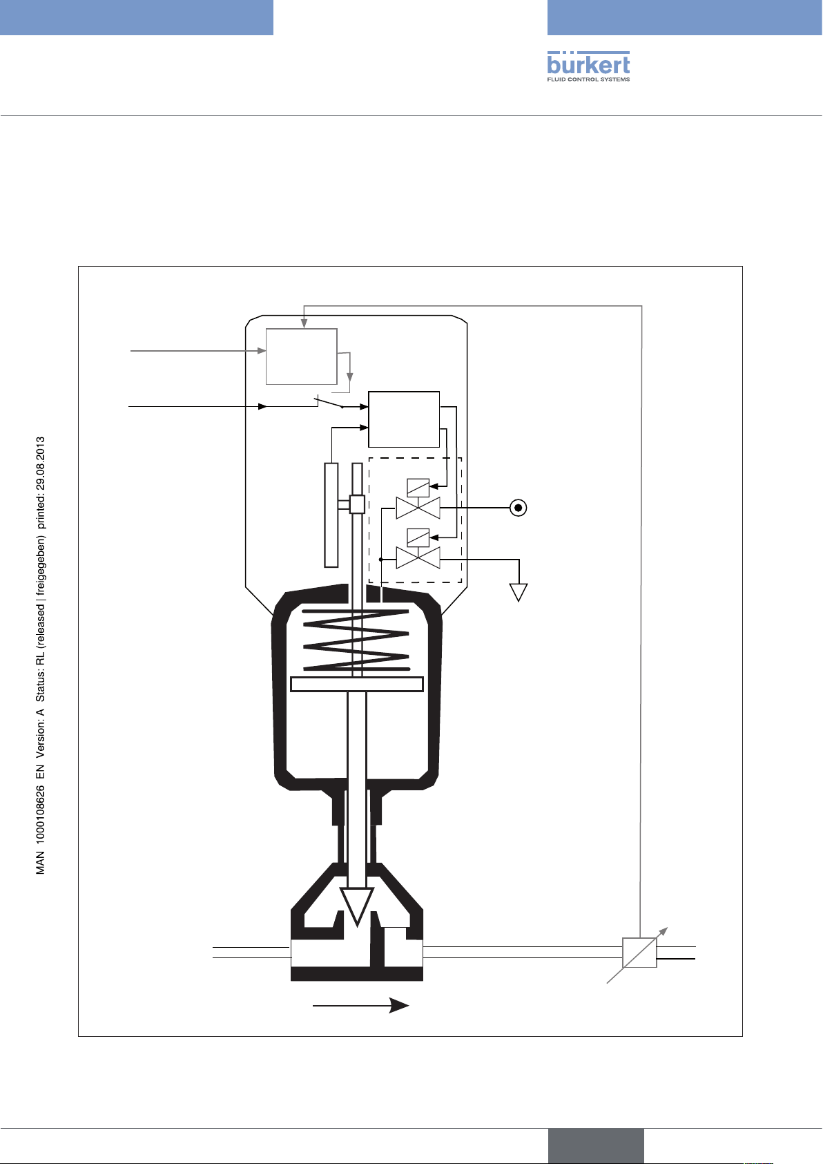
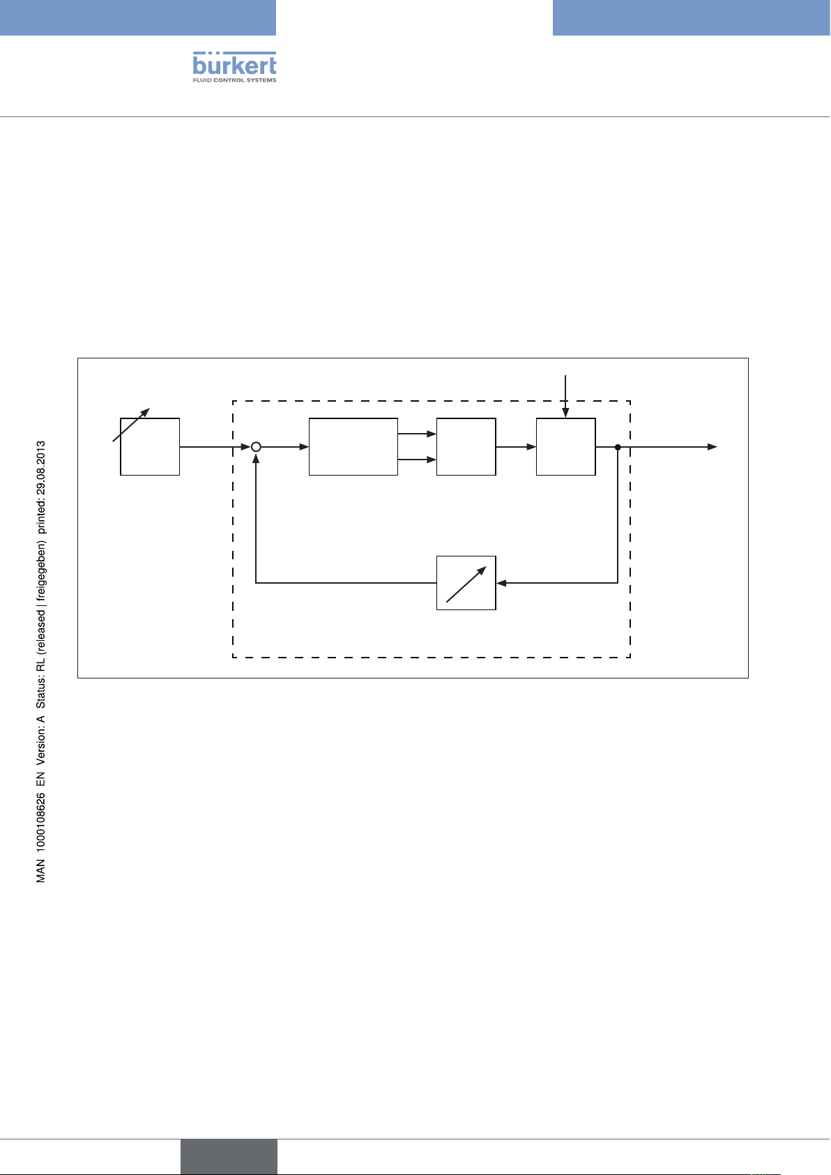
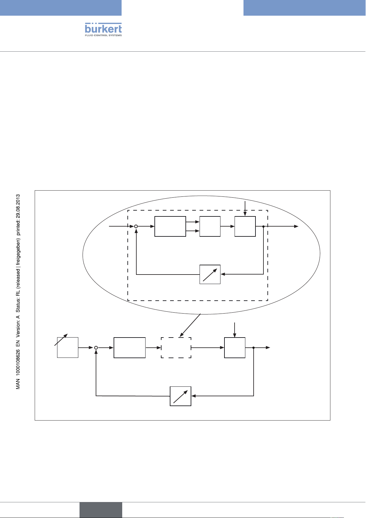
6.3. Function diagram of the positioner with single-
acting actuator
The black lines describe the function of the position controller (Type 8692). The process controller (Type 8693)
includes the position controller and the functions which are illustrated in grey.
Process actual value
Process set-point
value
External position
set-point value
Positioner
Process
controller
Actual
position
Position
measuring
system
Nominal position
Position
controller
Control system
1
2
Control system
1: Aeriation valve
2: Bleed valve
Compressedair supply
Pneumatic actuator
(single-acting)
Valve
Figure 3: Function diagram
Exhaust air
Sensor
Process actual value
(flow, pressure, level,
temperature, et cetera.)
19
english
Page 20
Type 8692, 8693
Description of system
7. TYPE 8692
POSITIONER WITH POSITION CONTROLLER
The position measuring system records the current position (POS) of the pneumatic actuator. The position controller
compares this actual position value with the set-point value (CMD), which is definable as norm signal. In case of
a control deviation (Xd1), a pulse-width modulated voltage signal is sent to the control system as a manipulated
variable. If there is a positive control difference in single-acting actuators, the air inlet valve is controlled via output
B1. If the control difference is negative, the bleed valve is controlled via output E1. In this way the position of the
actuator is changed until control difference is 0. Z1 represents a disturbance variable.
Z1
CMD Xd1
+
-
PositionerPosition set-
point value
Position control circuit
Figure 4: Signal flow plan of position controller
B1
E1
Control system
solenoid valves
POS
Position measuring
P
K
Continuous
valve
Valve opening
20
english
Page 21
Type 8692, 8693
Description of system,
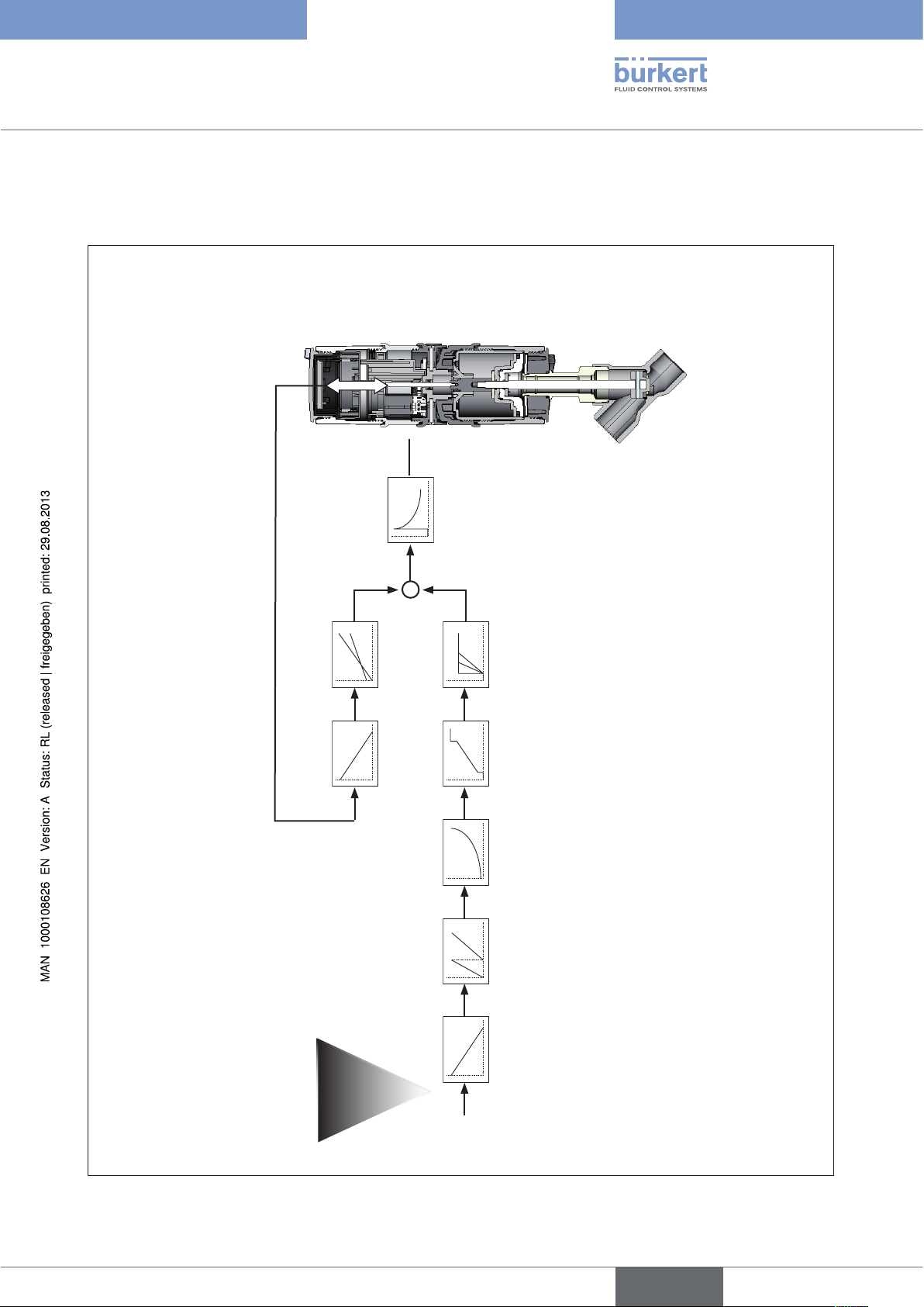
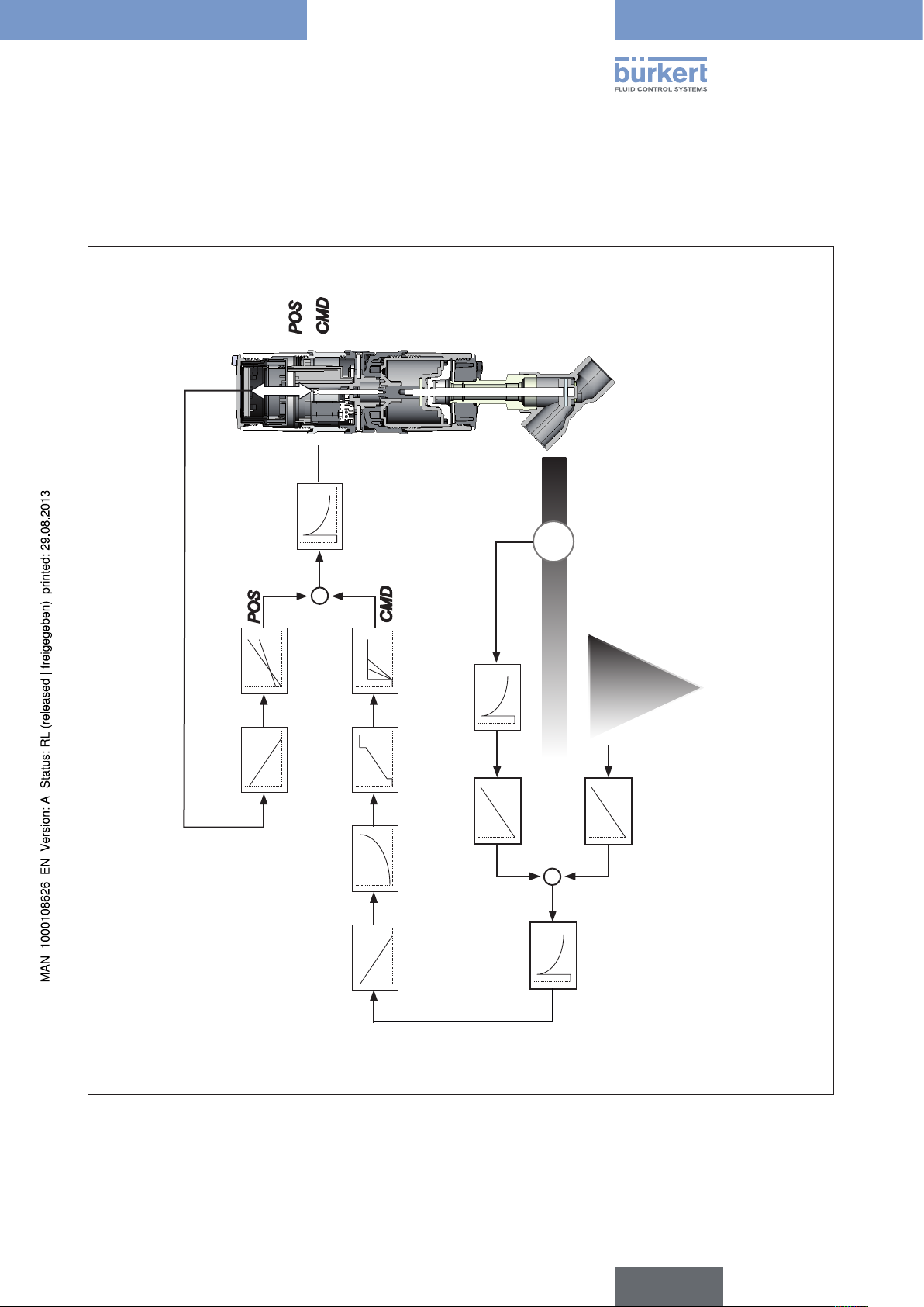
7.1. Schematic representation of the positioner
Type 8692
POS
CMD
TEMP
INPUT
POS
DIR.ACT X.LIMIT
X.CONTROL
DBND
CMD
4 ... 20 mA
0 ... 20 mA
0 ... 10 V
Figure 5: Schematic representation of position control
0 ... 5 V
DIR.CMD SPLTRNG CHARACT CUTOFF X.TIME
INP
21
english
Page 22
Type 8692, 8693
Description of system
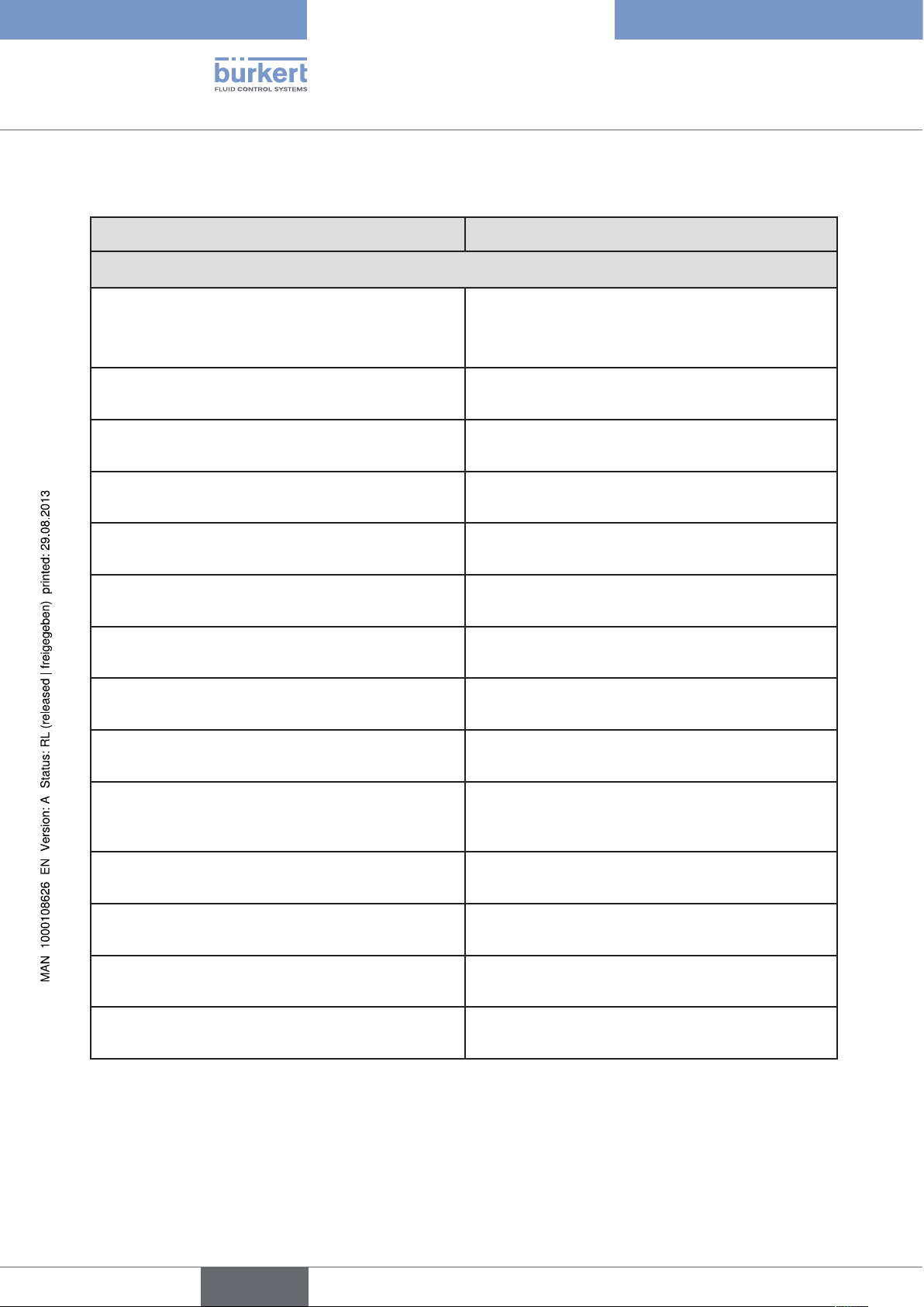
7.2. Properties of the position controller software
Additional function Action
Position controller with additional function
Sealing function
CUTOFF
Stroke limit
X.LIMIT
Signal range splitting
SPLTRNG
Correction line to adjust the operating characteristic
CHARACT
Insensitivity range
X.CONTROL
Effective direction of the controller nominal value
DIR.CMD
Safety position
SAFEPOS
Limit of the control speed
X.TIME
Effective direction of the actuator
DIR.ACT
Signal level error detection
Valve closes tight outside the control range. Specification of the value (in %), from which the actuator is
completely deaerated (when 0%) or aerated (when
100%).
Mechanical valve piston movement only within a
defined stroke range
Splitting of the standard signal range to two or more
positioners
The operating characteristic can be linearized
The position controller is initially actuated from a
control difference to be defined
Reversal of the effective direction of the nominal value
Definition of the safety position
Input of the opening and closing time for the entire
stroke
Adjustment of the effective direction between aeration
state of the actuator and the actual position
Check the input signals for sensor break.
22
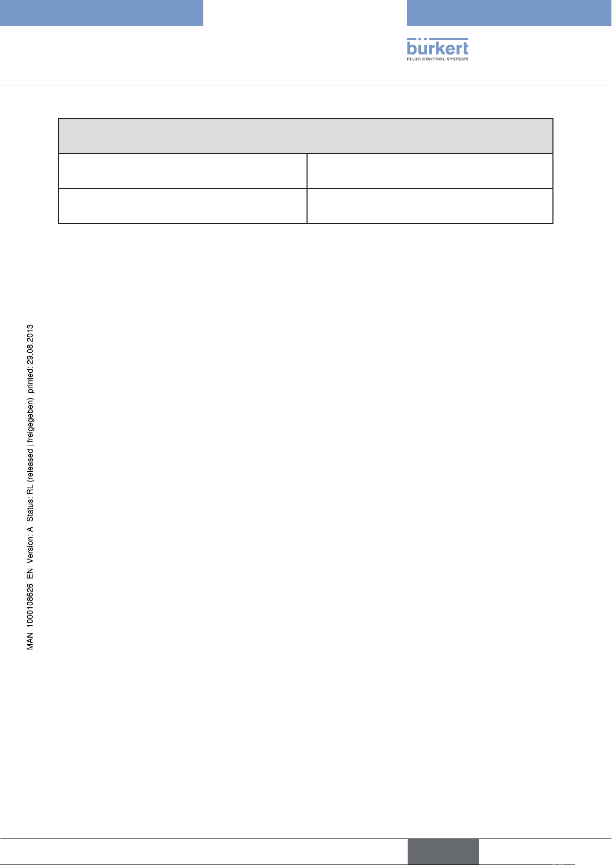
SIG.ERROR
Binary input
BINARY. IN
Analogue feedback (option)
OUTPUT
2 binary outputs (option)
OUTPUT
User calibration
CAL.USER
Table 2: Functions position controller
Warning output on the display and start up of the
safety position (if selected)
Switch over AUTOMATIC-MANUAL or
Start up of the safety position
Status signal set-point or actual value
Output of two selectable binary values.
Change to the factory calibration of the signal input
english
Page 23
Type 8692, 8693
Description of system,
Hierarchical control concept for easy control on the following levels
Process control On this level switch between AUTOMATIC and
MANUAL mode.
Configuration and parameterisation On this level specify certain basic functions during
start-up and, if required, configure additional functions
Table 3: Position controller - hierarchical control concept
english
23
Page 24
Type 8692, 8693
Description of system
8. TYPE 8693
POSITIONER WITH PROCESS CONTROLLER
If the positioner is operated with process controller Type 8693, the aforementioned position control becomes the
subordinate auxiliary control circuit; this results in a cascade control. The process controller in the main control
circuit of the positioner has a PID function. The process set-point value (SP) is specified as set-point value and
compared with the actual value (PV) of the process variable to be controlled. The position measuring system records
the current position (POS) of the pneumatic actuator. The position controller compares this actual position value
with the set-point value (CMD), which is determined by the process controller. In case of a control deviation (Xd1),
a pulse-width modulated voltage signal is sent to the control system as a manipulated variable. If there is a positive
control difference in single-acting actuators, the air inlet valve is controlled via output B1. If the control difference is
negative, the bleed valve is controlled via output E1. In this way the position of the actuator is changed until control
difference is 0. Z2 represents a disturbance variable.
SP
+
Process set-point
value
CMD
+
Xd2
Process controller
Xd1
-
Position
controller
Position control circuit
CMD
Position
control
circuit
B1
E1
Control system
solenoid valves
POS
Valve
opening
Z1
P
K
Continuous
valve
Position measuring
Z2
Process
Valve
opening
Process variable
24
PV
Transmitter
Figure 6: Signal flow plan of process controller
english
Page 25
Type 8692, 8693
Description of system,
8.1. Schematic representation of the process control
POS
CMDPVSP
TEMP
POS
-
DIR.ACT X.LIMIT
X.CONTROL
DBDx
+
CMD
PV SCALE
DIR.CMD CHARACT CUTOFF X.TIME
FILTER
PV
PV
Q
4 ... 20 mA
0 ... 20 mA
0 ... 10 V
0 ... 5 V
SP SCALE
SP
-
+
SP
P.CONTROL
PARAMETER
SETUP
Figure 7: Schematic representation of process control
25
english
Page 26
Type 8692, 8693
Description of system
8.2. Functions of the process controller software
Additional function Action
Position controller with additional function
Sealing function
CUTOFF
Stroke limit
X.LIMIT
Correction line to adjust the operating
characteristic
CHARACT
Insensitivity range
X.CONTROL
Effective direction of the controller nominal value
DIR.CMD
Safety position
SAFEPOS
Limit of the control speed
X.TIME
Effective direction of the actuator
DIR.ACT
Signal level error detection
Valve closes tight outside the control range. Specification
of the value (in %), from which the actuator is completely
deaerated (when 0%) or aerated (when 100%).
Mechanical valve piston movement only within a defined
stroke range
The operating characteristic can be linearized
The position controller is initially actuated from a control
difference to be defined
Reversal of the effective direction of the nominal value
Definition of the safety position
Input of the opening and closing time for the entire stroke
Adjustment of the effective direction between aeration
state of the actuator and the actual position
Check the input signals for sensor break.
26
SIG.ERROR
Binary input
BINARY. IN
Analogue feedback (option)
OUTPUT
2 binary outputs (option)
OUTPUT
User calibration
CAL.USER
Table 4: Functions position controller
Warning output on the display and start up of the safety
position (if selected)
Switch over AUTOMATIC-MANUAL or
Start up of the safety position
Status signal set-point or actual value
Output of two selectable binary values.
Change to the factory calibration of the signal input
english
Page 27
Type 8692, 8693
Description of system,
Additional function Action
Process controller with additional function
Controller structure
PID
P.CONTROL
Adjustable parameters
P.CONTROL - PARAMETER
Scalable inputs
P.CONTROL - SETUP
Selection of the nominal value specification
P.CONTROL - SETUP - SP INPUT
Process characteristic linearization
P.Q‘LIN
Process controller optimization
P.TUNE
Table 5: Functions process controller
Proportional coefficient, reset time, hold-back time and
operating point
Position of the decimal points, lower and upper scale
values of the actual process value and the process setpoint value
Set-point value specification either via standard signal
input or via keys
Function for automatic linearization of the process
characteristics
Function for automatic optimization of the process controller parameters
Hierarchical control concept for easy control on the following levels
Process control On this level switch between AUTOMATIC and MANUAL
mode.
Configuration and parameterization On this level specify certain basic functions during start-
up and, if required, configure additional functions
Table 6: Process controller - hierarchical control concept
english
27
Page 28
Type 8692, 8693
Description of system
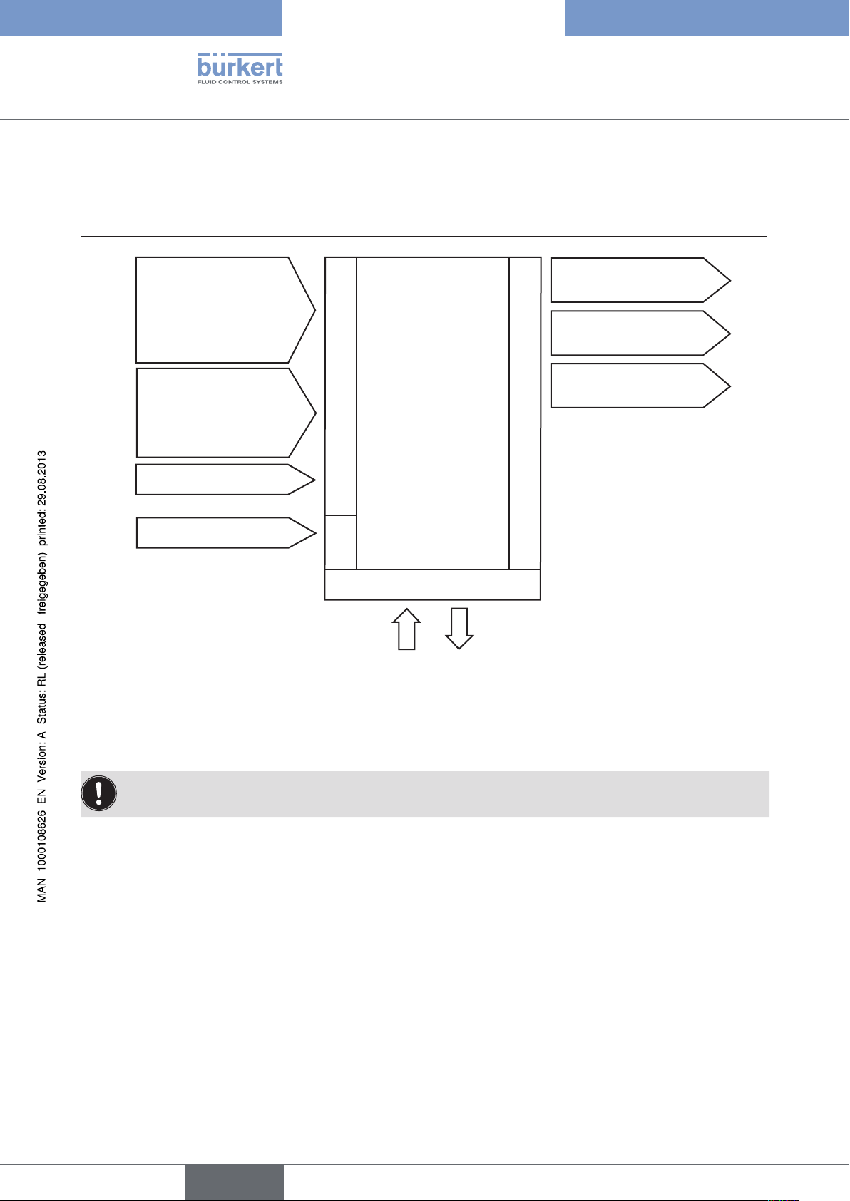
9. INTERFACES OF THE POSITIONER FOR THE
MULTIPOLE MODEL
Inputs for position or
process set-point value
4 – 20 mA
0 – 20 mA
0 – 10 V
0 – 5 V
Input for process
actual value
4 – 20 mA
Frequency
Pt 100
Binary input
24 V DC
Figure 8: Interfaces for the multipole model
Positioner
(Multipole model)
Inputs
Supply
Operation
2 binary outputs
Proximity switch 1
Analogue
position feedback
Outputs
28
The positioners Type 8692 and Type 8693 are 3-wire devices, i.e. the power (24 V DC) is supplied separately
from the set-point value signal.
english
Page 29
Type 8692, 8693
Description of system,
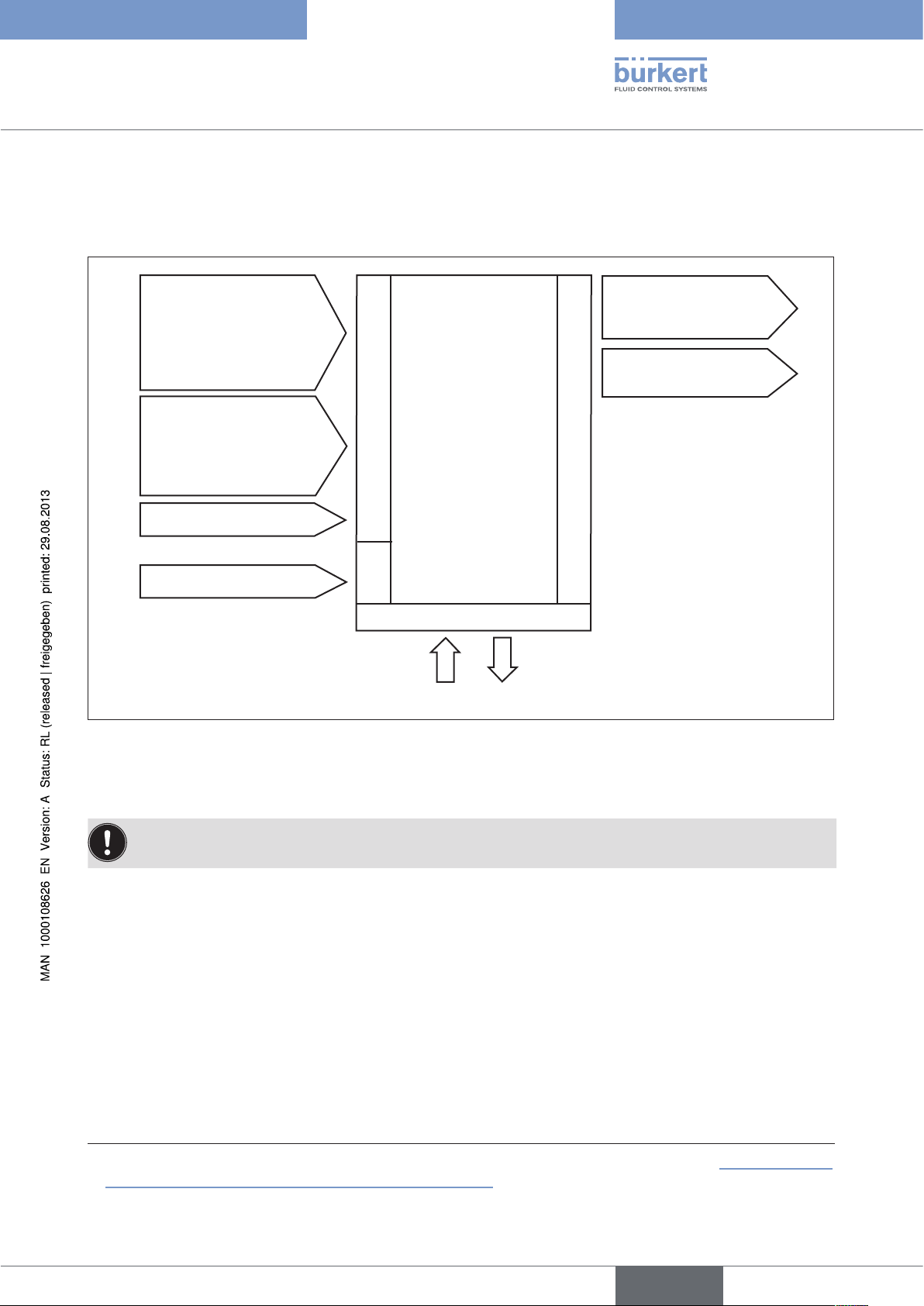
10. INTERFACES OF THE POSITIONER FOR THE
MODELS WITH CABLE GLAND
Inputs for position or
process set-point value
4 – 20 mA
0 – 20 mA
0 – 10 V
0 – 5 V
Input for process actual
1)
value
4 – 20 mA
Frequency
Inputs
Pt 100
Binary input
24 V DC
Figure 9: Interfaces for the model with cable gland
Supply
Positioner
(Cable gland)
Operation
2 binary outputs
(as an alternative to input
for process actual value)
Analogue position
feedback
Outputs
1)
The positioners Type 8692 and Type 8693 are 3-wire devices, i.e. the power (24 V DC) is supplied separately
from the set-point value signal.
1) Type 8693: The switch can be used to supply power to a connected sensor (description see “18.5.1 Terminal
assignment when selecting the process actual value input”)
english
29
Page 30
Type 8692, 8693
Description of system
11. TECHNICAL DATA
11.1. Safety positions after failure of the electrical or
pneumatic auxiliary power
Safety positions after failure of the auxiliary
Actuator system Designation
electrical pneumatic
power
pilot-controlled
control system:
up
down
up
down
up
down
single-acting
control function A
single-acting
control function B
double-acting
control function I
down
up
down / up
(depending on the con-
nection of the control
cables)
down
direct-acting
control system:
not defined
pilot-controlled
control system:
up
direct-acting
control system:
not defined
not defined
30
Table 7: Safety positions
english
Page 31

Type 8692, 8693
Description of system,
11.2. Factory settings of the positioner
Function Factory setting Function Factory setting
ACTUATOR SINGLE or DOUBLE
2)
INPUT 4-20 mA
CHARACT linear
DIR.CMD Rise
CUTOFF Min 0 %
Max 100 %
DIR.ACT Rise
SPLTRNG Min 0 %
Max 100 %
X.LIMIT Min 0 %
Max 100 %
X.TIME
Open (1s) Values of X.TUNE determined
Close (1s) Values of X.TUNE determined
After executing of SET.FACTORY: 1s
OUTPUT
OUT ANALOG Out POS
OUT type 4-20 mA
X.CONTROL
DBND 1.0 %
KXopn (1) Values of X.TUNE determined
KXcls (1) Values of X.TUNE determined
After executing of SET.FACTORY: 1
SECURITY
Access Code 1 0000
SAFEPOS 0 %
SIG.ERROR
SP/CMD Input Error off
P.CONTROL
PARAMETER
DBND 1.0 %
KP 1.00
TN 999.9
TV 0.0
X0 0.0 %
FILTER 0
SETUP
SP-INPUT intern
PV-INPUT 4-20 mA
PV-SCALE PVmin 0.0
PV-SCALE PVmax 100.0
P.CO-INIT bumpless
OUT BIN1 Out DEV.X
Lim. DEV.X 1.0 %
OUT.BIN1 type normally open
OUT BIN2 Out DEV.X
Lim. DEV.X 1.0 %
OUT.BIN1 type normally open
BINARY. IN SafePos
BIN. IN type normally open
Table 8: Factory settings
2) preset at the factory according to the actuator
31
english
Page 32

Type 8692, 8693
Description of system
11.3. Specifications of the positioner
11.3.1. Conformity
In accordance with the EC Declaration of conformity, the positioner Type 8692 and 8693 are compliant with the
EC Directives.
11.3.2. Standards
Conformity with the EC Directives is verified by the following standards.
EN 61000-6-3, EN 61000-6-2, EN 61010-1
11.3.3. Operating conditions
CAUTION!
Solar radiation and temperature fluctuations may cause malfunctions or leaks.
• If the device is used outdoors, do not expose it unprotected to the weather conditions.
• Ensure that the permitted ambient temperature does not exceed the maximum value or drop below the minimum value.
Ambient temperature 0 – + 55 °C
Protection class IP 65 / IP 67 in accordance with EN 60529
(only if cables, plugs and sockets have been connected correctly and in
compliance with the exhaust air concept in chapter “17.3. Pneumatic connection of
the positioner“)
11.3.4. Mechanical data
Dimensions see data sheet
Body material exterior: PPS, PC, VA, interior: PA 6; ABS
Sealing material NBR / EPDM
Stroke range of valve spindle 3 – 28 mm
32
11.3.5. Electrical data
Connections cable gland (24 V DC) or
circular plug-in connector (Profibus DP, DeviceNet, 24 V DC)
Supply voltage 24 V DC ± 10 % max. residual ripple 10 %
Power input < 5 W
english
Page 33

Type 8692, 8693
Description of system,
Input resistance 180 at 4 – 20 mA / 12 bit resolution
for actual value signal 17 k at frequency, 0 – 1000 Hz / 1‰ of measured value
> 300 mVss sine, square, triangle
Pt 100 -20 – +220 °C, resolution < 0.1 °C
Input resistance 180 at 0/4 – 20 mA / 12 bit resolution
for nominal value signal 19 k at 0 – 5/10 V / 12 bit resolution
Protection class 3 in accordance with VDE 0580
Analogue position feedback
max. current
for voltage output 0 – 5/10 V 10 mA
max. load
for current output 0/4 – 20 mA 560
Inductive proximity switches
current limitation 100 mA
Binary outputs galvanically isolated
Current limiting 100 mA, output is clocked
Binary input galvanically isolated
0 – 5 V = log "0", 10 – 30 V = log "1"
input inverted accordingly
11.3.6. Pneumatic Data
Control medium neutral gases, air
Quality classes in accordance with DIN ISO 8573-1
Dust content Class 5
max. particle size 40 µm, max. particle density 10 mg/m³
Water content Class 3
max. pressure dew point
-20 °C or min. 10 degrees below the lowest operating temperature
Oil content Class 5
max. 25 mg/m³
Temperature range 0 – +50 °C
Pressure range 3 – 7 bar
Air output, pilot valve 7 l
/ min (for aeration and deaeration)
N
(QNn value according to definition for pressure drop from 7 to 6 bar absolute)
Optional:
130 l
/ min (for aeration and deaeration)
N
(only single-acting)
Connections Plug-in hose connector Ø 6mm / 1/4”
Socket connection G1/8
33
english
Page 34

11.3.7. Type label
Type label (example)
Voltage supply / Controller
Type
8692 24 V DC
single act Pilot 0,6
Pmax 7 bar
Tamb 0°C - +55°C
S/N 001000
00177689
D-74653 Ingelfingen
W14UN
Type 8692, 8693
Description of system
Control function - pilot valve
Nominal pressure
Max. ambient temperature
CE
Serial number - CE mark
Identification number
Figure 10: Example of type label
Bar code
34
english
Page 35

Type 8692, 8693
Control and display elements, operating modes
Table of ConTenTs
12. CONTROL AND DISPLAY ELEMENTS ...................................................................................................................................36
12.1. Control and display elements of the positioner .................................................................................................36
12.2. Configuration of the keys ...............................................................................................................................................36
12.3. Information on the display .............................................................................................................................................38
13. OPERATING MODES .......................................................................................................................................................................39
13.1. AUTOMATIC operating state for Type 8692 ..........................................................................................................40
13.2. AUTOMATIC operating state for Type 8693 ..........................................................................................................40
13.3. MANUAL operating state ................................................................................................................................................42
14. OPERATING LEVELS .......................................................................................................................................................................43
14.1. Switching between the operating levels ................................................................................................................43
english
35
Page 36

Type 8692, 8693
Control and display elements,
operating modes
12. CONTROL AND DISPLAY ELEMENTS
The following chapter describes the control and display elements of the positioner.
Further information on the control of the positioner can be found in the chapters entitled “Installation”, “Start-up
and operation of the position controller Type 8692” and “Start-up and operation of the process controller Type
8693”.
12.1. Control and display elements of the positioner
POS
%
Description of
configuration of
the keys
Left selection key Right selection key
Up arrow key
Figure 11: Description of the control module
The positioner features a 4-key control panel and a 128x64 dot matrix graphics display as a display element.
MENU INPUT CMD MANU
XXX
Display
Down arrow key
12.2. Configuration of the keys
36
The assignment of the 4 keys on the control panel differs depending on the operating status (AUTOMATIC /
MANUAL) or operating level (Operate process / Parameterization and Configuration) of the positioner.
The configuration of the keys is represented in the lower grey bar on the display panel.
The description of the operating statuses (AUTOMATIC / MANUAL) and the operating levels (Operate
process / Parameterization and Configuration) can be found in the chapters entitled “13. Operating
modes” and “14. Operating levels”.
english
Page 37

Type 8692, 8693
Control and display elements,
operating modes
Key
Configuration
(indicated in the lower bar)
Up / down arrow key Change the display
(e.g. POS-CMD-TEMP-...)
OPN - CLS (OPEN - CLOSE)
manual opening and closing of the actuator
Scroll up and down the menus AUTOMATIC or MANUAL /
+ and increase or reduce numerical values
+ and
adjust numerical values by individual digits
Left selection key Switch to the Parameterization level (MENU)
Note:
the key must be pressed for approx. 3 s
(Countdown: 2 bars converge on the display
panel)
EXIT (BACK)
Operate process on the operating level
EXIT (BACK)
from a menu option on the operating level
Parameterization or Configuration
Operating status / Operating level
AUTOMATIC / Operate process
MANUAL / Operate process
Parameterization or Configuration
AUTOMATIC or MANUAL /
Parameterization or Configuration
AUTOMATIC or MANUAL /
Parameterization or Configuration
AUTOMATIC or MANUAL /
Operate process
AUTOMATIC or MANUAL /
Parameterization
AUTOMATIC or MANUAL /
Parameterization or Configuration
ESC
Leave a menu
STOP
End a sequence
Right selection key Switch between AUTOMATIC and MANUAL
mode
HOLD - CONT
Hold / continue of the graphic display of
process actual value and set-point value
Select, activate or deactivate a menu option
(ENTER, SELEC, OK, INPUT)
EXIT (BACK)
from a menu option on the operating level
Parameterization or Configuration
RUN
Start a sequence
STOP
End a sequence
Table 9: Configuration of the keys
AUTOMATIC or MANUAL /
Parameterization or Configuration
AUTOMATIC or MANUAL /
Parameterization or Configuration
Operate process
Operate process
AUTOMATIC or MANUAL /
Parameterization or Configuration
AUTOMATIC or MANUAL /
Parameterization or Configuration
AUTOMATIC or MANUAL /
Parameterization or Configuration
AUTOMATIC or MANUAL /
Parameterization or Configuration
english
37
Page 38

12.3. Information on the display
The following representation describes the information on the display:
Type 8692, 8693
Control and display elements,
operating modes
Description of
the value
POS
Unit or per-
centage of the
value
Configuration of the keys
Figure 12: Description of display
List of values which can be displayed in AUTOMATIC mode:
Representation of
value
POS % Display of actual position of the valve actuator
CMD % Display of nominal position of the valve actuator
Unit, value range Description
%
MENU INPUT CMD MANU
Display for AUTOMATIC mode:
Bar running from left to right
Value
XXX
Bar graph display
of the value
38
TEMP °C Internal temperature in the body of the positioner
INPUT mA, V Input signal for nominal position
PV (PROCESS
VALUE)
SP (SETPOINT) bar, mbar, psi, %, mm,
SP/PV(t)
Table 10: Representation of value
3) Unit depending on process actual value.
bar, mbar, psi, %, mm,
litre
l/s, l/min, l/h, m³/min,
m³/h, UG/s, UG/min,
UG/h, IG/s, IG/min, IG/h
°C, °F
litre
l/s, l/min, l/h, m³/min,
m³/h, UG/s, UG/min,
UG/h, IG/s, IG/min, IG/h
3)
°C, °F
Process actual value, 4 – 20 mA input
Process actual value, Frequency input
Process actual value, Pt 100 input
Process set-point value
Representation of process actual value and set-point value
english
Page 39

Type 8692, 8693
Control and display elements,
operating modes
13. OPERATING MODES
The positioner has 2 operating states: AUTOMATIC and MANUAL mode.
AUTOMATIC Normal controller mode is implemented and monitored in
AUTOMATIC operating state.
(A bar runs along the upper edge of the display).
MENU
MENU
The right selection key can be used to switch between the two operating states AUTOMATIC (AUTO) and MANUAL
(MANU).
OPN CLS
It is possible to switch from AUTOMATIC to MANUAL mode only on the POS and CMD displays and
also on the PV display for Type 8693. On the SP display only for external process set-point value
(see also “12.2. Configuration of the keys”).
MANU
MANUAL In MANUAL operating state the valve can be opened and
closed manually via the arrow key (OPN/CLS).
(No bar running along the upper edge of the display).
AUTO
english
39
Page 40

Type 8692, 8693
Control and display elements,
operating modes
13.1. AUTOMATIC operating state for Type 8692
(Bar runs along the upper edge of the display from left to right)
Normal controller mode is implemented and monitored in AUTOMATIC operating state.
The arrow keys can be used to switch between the following displays in AUTOMATIC operating state:
Display of actual position of the valve actuator
POS
%
MENU
INPUT
XXX
CMD MANU
(0 - 100%)
• Display of nominal position of the valve actuator or
CMD
%
MENU POS TEMP MANU
XXX
• Display of nominal position of the valve actuator after
rescaling by possibly activated split range function or
correction characteristic
(0 - 100%)
Internal temperature in the housing of the positioner
TEMP
*C
MENU CMD
XX.X
INPUT
INPUT
mA
MENU TEMP POS
Table 11: AUTOMATIC operating state for Type 8692
XXX
( °C)
Input signal for nominal position
(0 - 5/10 V or 0/4 – 20 mA)
13.2. AUTOMATIC operating state for Type 8693
(Bar runs along the upper edge of the display from left to right)
Normal controller mode is implemented and monitored in AUTOMATIC operating state.
40
If the P.CONTROL additional function is activated for Type 8693, it is possible to switch between the following
states in AUTOMATIC operating state:
english
Page 41

Type 8692, 8693
Control and display elements,
operating modes
POS
%
MENU SP CMD MANU
CMD
%
MENU POS TEMP MANU
TEMP
*C
XXX
XXX
XXX
Display of actual position of the valve actuator
(0 - 100%)
• Display of nominal position of the valve actuator or
• Display of nominal position of the valve actuator after
rescaling by possibly activated split range function or
correction characteristic
(0 - 100%)
Internal temperature in the body of the positioner
( °C)
MENU CMD PV
PV
l/s
MENU TEMP SP MANU
XXX
SP
l/s
MENU PV POS INPUT
MENU
Table 12: AUTOMATIC operating state for Type 8693
XXX
SP / PV ( t )
HOLD
4)
5)
Process actual value
Process set-point value
Representation of process actual value and set-point value
If the P.CONTROL additional function is not active, the displays are represented as under Type 8692.
4) INPUT is indicated here if the internal set-point value default has been selected (P.CONTROL - SP-INPUT -
internal).
MANU is indicated here if the external set-point value default has been selected (P.CONTROL - SP-INPUT
- external).
5) HOLD: hold the display - CONT: continue the display
english
41
Page 42

Type 8692, 8693
Control and display elements,
operating modes
13.3. MANUAL operating state
(no bar running along upper edge of display)
In MANUAL operating state the valve can be opened and closed manually via the arrow keys.
Meaning of the arrow keys in MANUAL operating state:
Press the up arrow key:
Aerate the actuator
Control function A (CFA): Valve opens
Control function B (CFB): Valve closes
Control function I (CFI): Connection 2.1 aerated
Press the down arrow key:
Deaerate the actuator
Control function A (CFA): Valve closes
Control function B (CFB): Valve opens
Control function I (CFI): Connection 2.2 aerated
Table 13: Meaning of the arrow keys - MANUAL operating state:
CFA: Actuator closes by spring force
CFA: Actuator opens by spring force
CFI: Actuator double-acting
42
english
Page 43

Type 8692, 8693
Control and display elements,
operating modes
14. OPERATING LEVELS
The menu structure in the control module of the positioner contains 2 operating levels:
• Level 1: Operate process
Operating mode AUTOMATIC Process / input data displayed
MANUAL Actuator opened and closed manually
• Level 2: Parameterization and configuration
Input operating parameters
Supplement the menu with optional menu options
14.1. Switching between the operating levels
If AUTOMATIC operating mode has been set when switching from level 1 (Operate process) to level 2
(Parameterization and Configuration), the process continues running while positioner settings are implemented on level 2.
To switch from level 1 (Operate process) to level 2 (Parameterization), press the selection key on the left
(MENU) for approx. 3 seconds. During these 3 seconds (Countdown) 2 bars converge (see “Figure 13”).
To switch back from level 2 (Parameterization and Configuration) to level 1 (Operate process), press the
selection key on the left (EXIT).
Switch to level 2: Parameterization Switch back to level 1: Operate process
M A I N
1
ENTER
MENU
MANU
ACTUATOR
INPUT
X. TUNE
ADD. FUNCTION
EXIT
Press selection key
on left for approx. 3
seconds
Figure 13: Switch operating level
2 bars which converge
Countdown
Press selection key
on left
43
english
Page 44

Type 8692, 8693
Control and display elements,
operating modes
44
english
Page 45

Type 8692, 8693
Installation
Table of ConTenTs
15. INSTALLATION ...................................................................................................................................................................................47
15.1. Safety instructions .............................................................................................................................................................47
15.2. Installation of the positioner Type 8692 and 8693
on process valves of series 2103, 2300 and 2301 ...........................................................................................48
15.3. Installing the positioner Type 8694 and Type 8693
on process valves belonging to series 26xx and 27xx ......................................................................................... 51
15.4. Rotating the actuator module ......................................................................................................................................54
15.5. Rotating the positioner for process valves belonging to series 26xx and 27xx ...............................56
16. FLUID CONNECTION ......................................................................................................................................................................57
16.1. Safety instructions .............................................................................................................................................................57
16.2. Installation of the process valve ................................................................................................................................. 57
16.3. Pneumatic connection of the positioner ................................................................................................................ 58
17. ELECTRICAL CONNECTION 24 V DC WITH CIRCULAR PLUG-IN CONNECTOR
(MULTI-POLE MODEL) ...................................................................................................................................................................59
17.1. Safety instructions .............................................................................................................................................................59
17.2. Type 8692 - designation of the circular plug-in connectors and the contacts .................................. 60
17.3. Connection of the position controller Type 8692 ..............................................................................................60
17.3.1. Input signals of the control centre (e.g. PLC) - circular plug M 12, 8-pole ...............................60
17.3.2. Output signals to the control centre (e.g. PLC) - circular plug M12 - 8-pole
(required for analogue output and/or binary output option only) ................................................. 61
17.3.3. Supply voltage (circular plug M12 - 4-pole) .....................................................................................61
17.3.4. Option: with proximity switch - socket M8, 4-pole..........................................................................61
17.4. Type 8693 - Designation of the circular plug-in connectors and the contacts .................................62
17.5. Connection of the process controller Type 8693 ..............................................................................................62
17.5.1. Process actual value (circular plug M 8, 4 pole) .............................................................................. 63
17.6. Setting the proximity switch - optional ...................................................................................................................64
english
45
Page 46

Type 8692, 8693
Installation
18. ELECTRICAL CONNECTION 24 V DC WITH CABLE GLAND .....................................................................................67
18.1. Safety instructions .............................................................................................................................................................67
18.2. Terminal board of the positioner with screw terminals and switches ...................................................68
18.3. Terminal assignment for cable gland - position controller Type 8692 ...................................................68
18.3.1. Input signals from the control centre (e.g. PLC) ..............................................................................68
18.3.2. Output signals to the control centre (e.g. PLC)
(required for analogue output and/or binary output option only) ................................................. 69
18.3.3. Supply voltage .........................................................................................................................................69
18.4. Terminal assignment for cable gland - process controller Type 8693 ...................................................70
18.4.1. Terminal assignment when selecting the process actual value input ..........................................71
19. INITIAL START-UP ............................................................................................................................................................................72
19.1. Safety instructions .............................................................................................................................................................72
19.2. Installation ..............................................................................................................................................................................72
19.3. Specifying the basic settings .......................................................................................................................................72
19.3.1. Setting the input signal (standard signal): .........................................................................................73
19.3.2. Running the automatic adjustment X.TUNE: ...................................................................................74
19.3.3. Overview of operating structure initial start-up ................................................................................ 75
46
english
Page 47

Type 8692, 8693
Installation
15. INSTALLATION
15.1. Safety instructions
DANGER!
Danger – high pressure in the equipment!
There is a serious risk of injury when reaching into the equipment.
• Before loosening the lines and valves, turn off the pressure and vent the lines.
WARNING!
Danger - improper installation!
Improper installation may result in injuries as well as damage to the device and the area around it.
• Fluid and electrical installations may be carried out by authorized technicians only and with the appropriate
tools!
Danger due to unintentional activation of the equipment!
Unintentional activation of the equipment during installation may result in injuries and damage.
• Take appropriate measures to prevent the equipment from being unintentionally activated.
english
47
Page 48

Type 8692, 8693
Installation
15.2. Installation of the positioner Type 8692 and 8693
on process valves of series 2103, 2300 and 2301
DANGER!
Danger – high pressure in the equipment!
There is a serious risk of injury when reaching into the equipment.
• Before loosening the lines and valves, turn off the pressure and vent the lines.
Procedure:
1. Install switch spindle
Transparent cap
Pilot air ports
(plug-in hose connectors with collets or
threaded bushings)
Actuator
Figure 14: Installation of the switch spindle (1), series 2103, 2300 and 2301
Unscrew the transparent cap on the actuator and unscrew the position display (yellow cap) on the spindle
extension (if present).
For version with plug-in hose connector, remove the collets (white nozzles) from both pilot air ports (if
present).
48
english
Page 49

Type 8692, 8693
Installation
10
Figure 15: Installation of the switch spindle (2), series 2103, 2300 and 2301
Puck holder
Switch spindle
Guide element
Groove ring
max. 1 Nm
max. 5 Nm
Actuator cover
O-ring
Spindle extension
NOTE!
Improper installation may damage the groove ring in the guide element!
The groove ring is already be pre-assembled in the guide element and must be “locked into position” in the
undercut.
• When installing the switch spindle, do not damage the groove ring.
Push the switch spindle through the guide element.
NOTE!
Screw locking paint may contaminate the groove ring!
• Do not apply any screw locking paint to the switch spindle.
To secure the switch spindle, apply some screw locking paint (Loctite 290) in the tapped bore of the spindle
extension in the actuator.
Check that the O-ring is correctly positioned.
Screw the guide element to the actuator cover (maximum torque: 5 Nm).
Screw switch spindle onto the spindle extension. To do this, there is a slot on the upper side
(maximum torque: 1 Nm).
Push puck holder onto the switch spindle and lock into position.
english
49
Page 50

Type 8692, 8693
Installation
2. Install sealing rings
Pull the form seal onto the actuator cover (smaller diameter points upwards).
Check that the O-rings are correctly positioned in the pilot air ports.
When the positioner is being installed, the collets of the pilot air ports must not be fitted to the actuator.
Pilot air port
Caution:
collets must not be
fitted !
Form seal
Installation of the form
seal
Figure 16: Installation of the sealing rings, series 2103, 2300 and 2301
3. Install positioner
NOTE!
Damaged printed circuit board or malfunction!
• Ensure that the puck holder is situated flat on the guide rail.
Align the puck holder and the positioner until
1. the puck holder can be inserted into the guide rail of the positioner (see “Figure 17”)
and
2. the supports of the positioner can be inserted into the pilot air ports of the actuator (see also “Figure 18”).
Guide rail
50
Puck holder
Figure 17: Aligning the puck holder
Push the positioner, without turning it, onto the actuator until no gap is visible on the form seal.
english
Page 51

Type 8692, 8693
Installation
NOTE!
Too high torque when screwing in the fastening screw does not ensure protection class IP65 / IP67!
• The fastening screws may be tightened to a maximum torque of 0.5 Nm only.
Attach the positioner to the actuator using the two side fastening screws. In doing so, tighten the screws only
hand-tight (max. torque: 0.5 Nm).
Supports
Pilot air ports
Figure 18: Installation of positioner, series 2103, 2300 and 2301
Fastening screws
max. 0.5 Nm
15.3. Installing the positioner Type 8694 and Type 8693
on process valves belonging to series 26xx and
27xx
Procedure:
1. Install switch spindle
Guide element
Spindle extension
Actuator
Figure 19: Installing the switch spindle (1), series 26xx and 27xx
Unscrew the already fitted guide element from the actuator (if present).
Remove intermediate ring (if present).
51
english
Page 52

Figure 20: Installing the switch spindle (2), series 26xx and 27xx
Press the O-ring downwards into the cover of the actuator.
Type 8692, 8693
Installation
Puck holder
Switch spindle
Switch spindle
Guide element
O-ring
Spindle (actuator)
Actuator size 125 and bigger with large air output:
remove existing spindle extension and replace with the new one. To do this, apply some screw locking paint
(Loctite 290) in the tapped bore of the spindle extension.
Screw the guide element into the cover of the actuator using a face wrench
6)
(torque: 8.0 Nm).
To secure the switch spindle, apply some screw locking paint (Loctite 290) to the thread of the switch spindle.
Screw the switch spindle onto the spindle extension. To do this, there is a slot on the upper side
(maximum torque: 1 Nm).
Push the puck holder onto the switch spindle until it engages.
6) Journal Ø: 3 mm; journal gap: 23.5 mm
2. Install positioner
NOTE!
Damaged printed circuit board or malfunction!
• Ensure that the puck holder is situated flat on the guide rail.
Push the positioner onto the actuator. The puck holder must be aligned in such a way that it is inserted into
the guide rail of the positioner.
52
Guide rail
Puck holder
Figure 21: Aligning the puck holder
english
Page 53

Type 8692, 8693
Installation
Press the positioner all the way down as far as the actuator and turn it into the required position.
Fastening
screws
max. 0.5 Nm
Figure 22: Installing the positioner
Ensure that the pneumatic connections of the positioner and those of the valve actuator are situated preferably vertically one above the other.
If they are positioned differently, longer hoses may be required other than those supplied in the accessory kit.
NOTE!
Too high torque when screwing in the fastening screw does not ensure protection class IP65 / IP67!
• The fastening screws may be tightened to a maximum torque of 0.5 Nm only.
Attach the positioner to the actuator using the two side fastening screws. In doing so, tighten the fastening
screws hand-tight only (maximum torque: 0.5 Nm).
3. Install pneumatic connection between positioner and actuator
Pilot air outlet 2
Pilot air outlet 2
Upper pilot air port
Figure 23: Installing the positioner
Lower pilot air port
1
2
Screw the plug-in hose connectors onto the positioner and the actuator.
Using the hoses supplied in the accessory kit, make the pneumatic connection between the positioner and
actuator with the following “Table 14: Pneumatic connection to actuator .
NOTE!
Damage or malfunction due to ingress of dirt and moisture!
• To comply with protection class IP65 / IP67, connect the control air connection which is not required to the
free chamber of the actuator or seal with a plug.
english
53
Page 54

Type 8692, 8693
Installation
Control function Pneumatic connection Type 8692, 8693 with actuator
Pilot air outlet
Pilot air port actuator
Type 8692, 8693
Process valve closed in rest position
A
(by spring force)
Process valve open in rest position (by
B
spring force)
2
1
2
2
2
1
2
2
2
1
lower chamber of the actuator
should be connected to the upper
chamber of the actuator
upper chamber of the actuator
should be connected to the lower
chamber of the actuator
lower chamber of the actuator
Process valve closed in rest position
2
2
upper chamber of the actuator
I
2
1
upper chamber of the actuator
Process valve open in rest position
Table 14: Pneumatic connection to actuator
2
2
lower chamber of the actuator
"In rest position" means that the pilot valves of the positioner Type 8694 are isolated or not actuated.
If the ambient air is humid, a hose can be connected between control air connection 22 of the positioner
and the unconnected chamber of the actuator for control function A or control function B. As a result, the
spring chamber of the actuator is supplied with dry air from the vent duct of the positioner.
54
15.4. Rotating the actuator module
The actuator module cannot be rotated unless there are straight seat and slanted seat valves!
Following installation of the process valve, if the positioner display is only partially visible or the connection cables
or hoses cannot be fitted properly, the actuator module (positioner and actuator) can be rotated into a position
suitable for the connection.
Only the entire actuator module can be rotated. The positioner cannot be rotated contrary to the actuator.
The process valve must be in the open position for alignment of the actuator module!
DANGER!
Danger – high pressure in the equipment!
There is a serious risk of injury when reaching into the equipment.
• Before loosening the lines and valves, turn off the pressure and vent the lines.
Procedure:
Clamp valve body in a holding device (only required if the process valve has not yet been installed).
english
Page 55

Type 8692, 8693
Installation
NOTE!
Damage to the seat seal or the seat contour!
• When removing the actuator module, ensure that the valve is in open position.
Control function A: Open process valve.
Actuator
module
Key contour
Nipple
without hexagon
Figure 24: Rotating the actuator module
Hexagon
Nipple
with hexagon
Using a suitable open-end wrench, counter the wrench flat on the pipe.
Actuator module without hexagon: Fit special key
7)
exactly in the key contour on the underside of the actuator.
Actuator module with hexagon: Place suitable open-end wrench on the hexagon of the actuator.
WARNING!
Risk of injury from discharge of medium and pressure!
If the direction of rotation is wrong, the body interface may become detached.
• Rotate the actuator module in the specified direction only (see “Figure 25”) !
Actuator module without hexagon:
Rotate clockwise (as seen from below) to bring the actuator module into the required position.
Actuator module with hexagon:
Rotate counter-clockwise (as seen from below) to bring the actuator module into the required position.
Open-end wrench
Special key
with hexagon
Figure 25: Rotating with special key / open-end wrench
7) The special key (665702) is available from your Bürkert sales office.
without hexagon
55
english
Page 56

Type 8692, 8693
Installation
15.5. Rotating the positioner for
process valves belonging to series 26xx and 27xx
If the connecting cables or hoses cannot be fitted properly following installation of the process valve, the positioner
can be rotated contrary to the actuator.
Positioner
Fastening screw (2x)
Pneumatic connection
Actuator
Figure 26: Rotating the positioner, series 26xx and 27xx
Procedure
Loosen the pneumatic connection between the positioner and the actuator.
Loosen the fastening screws (hexagon socket wrench size 2.5).
Rotate the positioner into the required position.
NOTE!
Too high torque when screwing in the fastening screw does not ensure protection class IP65 / IP67!
• The fastening screw may be tightened to a maximum torque of 0.5 Nm only.
56
Tighten the fastening screws hand-tight only (maximum torque: 0.5 Nm).
Re-attach the pneumatic connections between the positioner and the actuator. If required, use longer hoses.
english
Page 57
Type 8692, 8693
Installation
16. FLUID CONNECTION
The dimensions of the positioner and the different complete device models, consisting of positioner, actuator and
valve, can be found in the relevant data sheets.
16.1. Safety instructions
DANGER!
Danger – high pressure in the equipment!
There is a serious risk of injury when reaching into the equipment.
• Before loosening the lines and valves, turn off the pressure and vent the lines.
WARNING!
Danger - improper installation!
Improper installation may result in injuries as well as damage to the device and the area around it.
• Fluid and electrical installations may be carried out by authorized technicians only and with the appropriate
tools!
Danger due to unintentional activation of the equipment!
Unintentional activation of the equipment during installation may result in injuries and damage.
• Take appropriate measures to prevent the equipment from being unintentionally activated.
16.2. Installation of the process valve
Thread type and dimensions can be found in the corresponding data sheet.
Connect the valve according to the operating instructions for the valve.
english
57
Page 58

Type 8692, 8693
Installation
16.3. Pneumatic connection of the positioner
DANGER!
Risk of injury from high pressure!
• Before dismounting pneumatic lines and valves, turn off the pressure and vent the lines.
Procedure:
Connect the control medium to the pilot air port (1)
(3 – 7 bar; instrument air, free of oil, water and dust).
Attach the exhaust air line or a silencer to the exhaust air port (3)
and, if available to the exhaust air port (3.1)
Important information for the problem-free functioning of the device:
• The installation must not cause back pressure to build up.
• Select a hose for the connection with an adequate cross-section.
• The exhaust air line must be designed in such a way that no water or other liquid can get into the
device through the exhaust air port (3) or (3.1).
Exhaust air port
(label: 3)
Pilot air port
(label: 1)
Additional exhaust air port
(label: 3.1)
only for Type 23xx and 2103
with pilot-operated control system
for high air output (actuator size ø 125 /130)
58
Figure 27: Pneumatic Connection
Caution:(Exhaust air concept):
In compliance with protection class IP67, an exhaust air line must be installed in the dry area.
Keep the adjacent supply pressure always at least 0.5 – 1 bar above the pressure which is required to
move the actuator to its end position. This ensures that the control behavior is not extremely negatively
affected in the upper stroke range on account of too little pressure difference.
During operation keep the fluctuations of the pressure supply as low as possible (max. ±10 %). If fluctuations are greater, the control parameters measured with the X.TUNE function are not optimum.
english
Page 59

Type 8692, 8693
Installation
17. ELECTRICAL CONNECTION 24 V DC WITH
CIRCULAR PLUG-IN CONNECTOR (MULTIPOLE MODEL)
17.1. Safety instructions
DANGER!
Danger - electrical voltage in the equipment!
There is a serious risk of injury when reaching into the equipment.
• Before starting work, always switch off the power supply and safeguard to prevent re-activation!
WARNING!
Danger - improper installation!
Improper installation may result in injuries as well as damage to the device and the area around it.
• Fluid and electrical installations may be carried out by authorized technicians only and with the appropriate
tools!
Danger due to unintentional activation of the equipment!
Unintentional activation of the equipment during installation may result in injuries and damage.
• Take appropriate measures to prevent the equipment from being unintentionally activated.
Using the 4 - 20 mA nominal value input
If the operating voltage of one positioner device fails in a series connection of several devices, the input
of the failed positioner device becomes highly resistive. As a result, the 4 - 20 mA standard signal fails. In
this case please contact Bürkert Service directly.
If PROFIBUS DP or DeviceNet:The designation of the circular plug-in connectors and sockets and the
contacts can be found in the respective chapters.
english
59
Page 60

Type 8692, 8693
Installation
17.2. Type 8692 - designation of the circular plug-in
connectors and the contacts
3
2
4
5
6
2
3
4
2
4
3
Circular plug M12, 8-pole
1
Input signals of the control centre
8
Output signals to the control centre
7
(option)
Circular plug M12, 4-pole
1
Supply voltage
Socket M4, 4-pole
1
Option: Proximity switch
Figure 28: Designation of the circular plug-in connectors and contacts 8692
17.3. Connection of the position controller Type 8692
17.3.1. Input signals of the control centre (e.g. PLC) - circular plug
M 12, 8-pole
Pin Wire color8)Configuration External circuit / signal level
8 red
7 blue Set-point value GND
1 white Binary input + (only option)
Table 15: Pin assignment - Input signals of the control centre - circular plug M 12, 8-pole
Set-point value + (0/4 – 20 mA
or 0 – 5 / 10 V)
8
+ (0/4 - 20 mA or 0 - 5 / 10 V)
completely galvanically isolated
7 GND
1 + 0 - 5 V (log. 0)
10 - 30 V (log. 1)
60
english
Page 61

Type 8692, 8693
Installation
17.3.2. Output signals to the control centre (e.g. PLC) - circular
plug M12 - 8-pole (required for analogue output and/or
binary output option only)
Connect the pins according to the design (options) of the positioner.
Pin Wire color
6 pink Analogue position feedback +
5 grey
4 yellow Binary output 1
3 green Binary output 2
2 brown Binary outputs GND
Table 16: Pin assignment -Output signals to the control centre - circular plug M 12 - 8-pole
8)
Configuration external circuit / signal level
6
Analogue position feedback
GND
5 GND
4
3
2
+ (0/4 - 20 mA or 0 - 5 / 10 V)
completely galvanically isolated
24 V / 0 V
24 V / 0 V
GND
17.3.3. Supply voltage (circular plug M12 - 4-pole)
Pin Wire color9)Configuration External circuit
1 brown + 24 V
2 not assigned
3 blue GND
4 not assigned
1
24 V DC ± 10 %
max. residual ripple 10 %
3
Table 17: Pin assignment - Supply voltage - (circular plug M 12 - 4-pole)
17.3.4. Option: with proximity switch - socket M8, 4-pole
Pin Wire color
1 brown Proximity switch 1 out
2 white GND
3 blue + 24 V DC
4 not assigned
Table 18: Pin assignment - proximity switch - socket M 8, 4-pole
When the supply voltage is applied, the positioner is operating.
10)
Configuration External circuit
3
1
Proximity switch
2
Now implement the required basic settings and activate automatic adjustment of the positioner as described in
the chapter entitled “19. Initial start-up” or “Starting and setting up the position controller Type 8692”.
8) The indicated colors refer to the connecting cable available as an accessory (919061)
9) The indicated colors refer to the connecting cable available as an accessory (918038)
10) The indicated colors refer to the connecting cable available as an accessory (92903475)
61
english
Page 62

Type 8692, 8693
Installation
17.4. Type 8693 - Designation of the circular plug-in
connectors and the contacts
3
2
Circular plug M12, 8-pole
4
5
6
1
Input signals of the control centre
8
Output signals to the control centre
7
(option)
3
1
Circular plug M8, 4-pole
Process actual value
24
2
Circular plug M12, 4-pole
3
4
4
1
Voltage supply
2
Socket M8, 4-pole
3
1
Option: Proximity switch
Switch
(behind the screw)
Figure 29: Designation of the circular plugs and contacts 8693
17.5. Connection of the process controller Type 8693
62
First connect the process controller as described in the chapter entitled “17.3 Connecting the position con-
troller Type 8692”.
english
Page 63

Type 8692, 8693
Installation
17.5.1. Process actual value (circular plug M 8, 4 pole)
Input type
4 – 20 mA
- internally
supplied
4 – 20 mA
- externally
supplied
Frequency
- internally
supplied
Frequency
- externally
supplied
11)
Pin
1
2
3
4
1
2
3
4
1
2
3
4
1
2
3
4
Wire
color
brown
white
blue
black
brown
white
blue
black
brown
white
blue
black
brown
white
blue
black
Configuration Switch External circuit
12)
+ 24 V transmitter supply
Output from transmitter
1
2
GND
Bridge after GND (GND from
3-wire transmitter)
Switch
on
left
3
4
Not assigned
Process actual +
Not assigned
Process actual -
+ 24 V sensor supply
Switch
on right
2
4 GND
1
Clock input +
Clock input - (GND)
Not assigned
Switch
on
left
2
3
Not assigned
Clock input +
Clock input -
Not assigned
Switch
on right
2
3 Clock -
I
Transmitter
GND
4 – 20 mA
+ 24 V
Clock +
Clock -
Clock +
Pt 100
(see information below)
Table 19: Process actual value
1
brown
2
white
3
blue
4
black
Not assigned
Process actual 1 (current feed)
Process actual 2 (GND)
Process actual 3
(compensation)
Switch
on right
2
3
4
For reasons of wire compensation connect the Pt 100 sensor via 3 wires. Always bridge Pin 3 and Pin 4
on the sensor.
When the supply voltage is applied, the positioner is operating.
Now implement the required basic settings and activate automatic adjustment of the positioner as described
in the chapter entitled “19. Initial start-up” or “Starting and setting up the process controller Type 8693”.
11) Can be adjusted by software (see chapter entitled “19.3 Specifying the basic settings”)
12) The indicated colors refer to the connecting cable available as an accessory (918718)
Pt 100
63
english
Page 64

Type 8692, 8693
Installation
17.6. Setting the proximity switch - optional
In the positioner with proximity switch option, the latter can be set to the bottom or the top end position.
DANGER!
Risk of electric shock!
• Before reaching into the system, switch off the power supply and secure to prevent reactivation!
• Observe applicable accident prevention and safety regulations for electrical equipment!
Figure 30: Setting the proximity switches
Electronics module
Jumper
Setting screw
Home position jumper
Setting
bottom end position CFA and CFI
or
top end position CFB
Jumper set
Setting
top end position CFA and CFI
or
bottom end position CFB
64
Procedure:
1. Open body and take off electronics module:
Disconnect supply voltage at the positioner and proximity switch connector.
Unscrew body casing (with transparent hood).
Remove electronics module.
english
Page 65

Type 8692, 8693
Installation
2. Setting the proximity switches (depending on the control function):
Bottom end position for control function A or top end position for control function B
Switch on supply voltage at the proximity switch connector.
Using a screwdriver, set proximity switch at the setting screw to end position.
Switch off supply voltage at the proximity switch connector.
Bottom end position for control function I
Connect the pilot air.
WARNING!
Valve moves after electrical voltage has been connected!
After connecting the electrical voltage, the actuator moves to the set end position!
• Never perform setting of the proximity switch while a process is running!
Switch on supply voltage at the positioner and proximity switch connector.
Move actuator to the bottom end position.
Using a screwdriver, set proximity switch at the setting screw to end position.
Switch off the pilot air.
Disconnect supply voltage at the positioner and proximity switch connector.
Top end position for control function A and I or bottom end position for control function B
Set jumper (see “Figure 30: Setting the proximity switches”).
Connect the pilot air.
WARNING!
Valve moves after electrical voltage has been connected!
After connecting the electrical voltage, the actuator moves to the set end position!
• Never perform setting of the proximity switch while a process is running!
Switch on supply voltage at the positioner / process controller and proximity switch connector.
Move actuator to the top end position (CFA and I) or bottom end position (CFB).
Using a screwdriver, set proximity switch at the setting screw to end position.
Switch off the control air.
Switch off supply voltage at the unit and the proximity switch connector.
Return jumper to home position (“Figure 30: ”).
english
65
Page 66

Type 8692, 8693
Installation
3. Attach electronics module and close body:
NOTE!
Be careful not to damage the pins at the PCB!
• When installing the electronics module, observe positioning of the pins to the PCB on the electronics
module.
Attach electronics module carefully and insert the pins in the PCB on the electronics module.
Check that the seal is correctly positioned in the body casing.
Seal
body casing
Figure 31: Position of the seal in the body casing
NOTE!
Damage or malfunction due to ingress of dirt and moisture!
To ensure protection class IP65 / IP 67:
• Screw in body casing to the stop.
Screw in body casing (with transparent cap) (screwing tool: 674077
13)
).
Switch on supply voltage at the unit and the proximity switch connector.
Restart operation of positioner.
13) The screwing tool (674077) is available through your Bürkert sales office.
66
english
Page 67

Type 8692, 8693
Installation
18. ELECTRICAL CONNECTION 24 V DC
WITH CABLE GLAND
18.1. Safety instructions
DANGER!
Danger - electrical voltage in the equipment!
There is a serious risk of injury when reaching into the equipment.
• Before starting work, always switch off the power supply and safeguard to prevent re-activation!
WARNING!
Danger - improper installation!
Improper installation may result in injuries as well as damage to the device and the area around it.
• Fluid and electrical installations may be carried out by authorized technicians only and with the appropriate
tools!
Danger due to unintentional activation of the equipment!
Unintentional activation of the equipment during installation may result in injuries and damage.
• Take appropriate measures to prevent the equipment from being unintentionally activated.
Using the 4 - 20 mA nominal value input
If the operating voltage of one positioner device fails in a series connection of several devices, the input
of the failed positioner device becomes highly resistive. As a result, the 4 - 20 mA standard signal fails. In
this case please contact Bürkert Service directly.
english
67
Page 68

Type 8692, 8693
Installation
18.2. Terminal board of the positioner with screw
terminals and switches
Switch
1
Figure 32: Terminal board with screw terminals and switch
Procedere:
1
2
3
4
5
6
7
12
13
14
8
9
10
11
Screw terminals
The connection terminals can be accessed by removing the cover from the cable glands. To do this, unscrew
the 4 screws.
Connect the positioner accordingly:
Type 8692: see chapter entitled “18.3 Terminal assignment for cable gland - position controller Type 8692”
Type 8693: see chapter entitled “18.4 Terminal assignment for cable gland - process controller Type 8693”
68
18.3. Terminal assignment for cable gland - position
controller Type 8692
18.3.1. Input signals from the control centre (e.g. PLC)
Terminal Configuration External circuit
11
10
12
13
Table 20: Configuration screw terminals - input signals from the control centre
Set-point value +
Set-point value GND
Binary input + (optional only)
Binary input GND (optional only)
english
11
10 GND
12
13 GND
+ (0/4 – 20 mA or 0 – 5 / 10 V)
+ 0 – 5 V (log. 0)
10 – 30 V (log. 1)
Page 69

Type 8692, 8693
Installation
18.3.2. Output signals to the control centre (e.g. PLC)
(required for analogue output and/or binary output option
only)
Connect the terminals according to the design (options) of the positioner.
Terminal Configuration External circuit
9
8
5
6
7
6
Table 21: Configuration screw terminals - Output signals to the control centre
Analogue position feedback +
Analogue position feedback GND
Binary output 1
Binary output GND
Binary output 2
Binary output GND
9
8 GND
5
6 GND
7
6 GND
18.3.3. Supply voltage
Terminal Configuration External circuit
14
13
Supply voltage +
Supply voltage GND
14
13
+ (0/4 – 20 mA or 0 – 5 / 10 V)
completely galvanically isolated
24 V / 0 V NC / NO
24 V / 0 V NC / NO
24 V DC ± 10 %max.
residual ripple 10 %
Table 22: Configuration screw terminals - Supply voltage
When the supply voltage is applied, the positioner is operating.
Now implement the required basic settings and activate automatic adjustment of the positioner as described in
the chapter entitled “19. Initial start-up” or “Starting and setting up the position controller Type 8692”.
69
english
Page 70

Type 8692, 8693
Installation
18.4. Terminal assignment for cable gland - process
controller Type 8693
First connect the process controller as described in the chapter entitled “18.3 Terminal assignment for cable
gland - position controller Type 8692”.
Connect the screw terminals of the process actual value input.
Switch
1
Figure 33: Terminal board with screw terminals and switch
1
2
3
4
5
6
7
12
13
14
8
9
10
11
Screw terminals
70
english
Page 71

Type 8692, 8693
Installation
18.4.1. Terminal assignment when selecting the process actual
value input
Input type
4 – 20 mA
- internally
supplied
14)
Switch
15)
Terminal Configuration External circuit
1
2
3
4
1
2
Frequency
- internally
supplied
Switch
on left
3
4
4 – 20 mA
- externally
supplied
1
2
3
4
Frequency
- externally
supplied
Switch on
right
Pt 100
(see information
below)
1
2
3
4
1
2
3
4
Table 23: Process actual value input
+ 24 V transmitter input
Transmitter output
Bridge after GND (GND from
3-wire transmitter)
GND
+ 24 V sensor supply
Clock input +
Not assigned
Clock input - (GND)
Not assigned
Process actual +
Process actual -
Not assigned
Not assigned
Clock input +
Not assigned
Clock input Not assigned
Process actual 1 (current feed)
Process actual 2
(compensation)
Process actual 3 (GND)
1
2
3
I
Transmitter
GND
4
1
2
4
2
+ 24 V
Clock +
Clock - (GND)
+ (4 – 20 mA)
3 GND
2
Clock +
4 Clock -
2
Pt 100
3
4
For reasons of wire compensation connect the Pt 100 sensor via 3 wires.
Always bridge Terminal 3 and Terminal 4 on the sensor.
When the power supply voltage is applied, the positioner is operating.
Now implement the required basic settings and activate automatic adjustment of the positioner as described
in the chapter entitled “19. Initial start-up” or “Starting and setting up the process controller Type 8693”.
14) Can be adjusted by software (see chapter entitled “19. 3 Specifying the basic settings”)
15) The switch is situated on the terminal board of the positioner (see “Figure 33”)
english
71
Page 72

Type 8692, 8693
Installation
19. INITIAL START-UP
This section enables you to start up the positioner quickly in order to perform a function check. Additional
functions which are not required are not dealt with in this context.
19.1. Safety instructions
DANGER!
Danger – high pressure in the equipment!
There is a serious risk of injury when reaching into the equipment.
• Before loosening the lines and valves, turn off the pressure and vent the lines.
WARNING!
Danger - improper installation!
Improper installation may result in injuries as well as damage to the device and the area around it.
• Fluid and electrical installations may be carried out by authorized technicians only and with the appropriate
tools!
Danger due to unintentional activation of the equipment!
Unintentional activation of the equipment during installation may result in injuries and damage.
• Take appropriate measures to prevent the equipment from being unintentionally activated.
19.2. Installation
Before start-up, carry out fluid and electrical installation of the positioner and valve.
When the operating voltage is applied, the positioner is operating and is in the AUTOMATIC operating state.
19.3. Specifying the basic settings
The basic settings of the positioner are implemented at the factory.
72
Before the positioner can undergo a function check, the unit input signal (standard signal) must still be set following
installation of the device and the X.TUNE function run to adjust the device to local conditions.
To specify the basic settings, switch from the process operating level to the configuration level.
Hold down the left selection key (MENU) for approx. 3 seconds (countdown: two bars converge on the
display).
Then the main menu (MAIN) is indicated on the display together with the menu options which can be individually
marked via the arrow keys and then selected via the right selecion key (ENTER).
english
Page 73

Type 8692, 8693
Installation
POS
%
Description of
configuration of
the keys
Left selection key Right selection key
Up arrow key
Figure 34: Description of the control module
An overview of the operating structure of the basic settings can be found in the chapter entitled “19.3.3
Overview of operating structure – Initial start-up” .
MENU INPUT CMD MANU
XXX
Display
Down arrow key
19.3.1. Setting the input signal (standard signal):
Using the arrow keys, mark the INPUT menu option in the main menu and then press the right selection key
(ENTER) to enter the INPUT submenu.
Using the arrow keys, mark the input signal (4 - 20 mA, 0 - 20 mA, ...).
Press the right selection key (SELEC) to select the input signal (dot is marked).
To leave the submenu, press the left selection button (EXIT).
To leave the main menu, press the left selection button (EXIT) again.
You have to leave the main menu by pressing the left selection button (EXIT) before the modified data is
saved in the memory (EEPROM). During the save process the message “SAVE EEPROM” is indicated on
the display.
73
english
Page 74

Type 8692, 8693
Installation
19.3.2. Running the automatic adjustment X.TUNE:
An exact description of the X.TUNE function can be found in the chapters entitled "Start-up and operating
the position controller Type 8692"
WARNING!
Danger due to the valve position changing when the X.TUNE function is running!
When the X.TUNE is running under operating pressure, there is an acute risk of injury.
• Never run X.TUNE while a process is running!
• Take appropriate measures to prevent the equipment from being accidentally actuated!
NOTE!
Avoid maladjustment of the controller due to an incorrect pilot pressure or applied operating medium
pressure!
• Run X.TUNE whenever the pilot pressure (= pneumatic auxiliary energy) is available during subsequent
operation.
• Run the X.TUNE function preferably without operating medium pressure to exclude interference caused by
flow forces.
To enter the main menu, hold down the left selection button (MENU) for approx. 3s (countdown on the
display).
Using the arrow buttons, mark the X.TUNEmenu option.
To start the automatic adjustment X.TUNE , hold down the right selection button (RUN) for approx. 3s
(countdown on the display).
While the automatic adjustment is running, messages on the progress of the X.TUNE (e.g. “TUNE #1....”) are indi-
cated on the display.
When the automatic adjustment completes, the message “X.TUNE READY” is indicated.
Press any key to return to the main menu.
To leave the main menu, press the left selection button (EXIT).
You have to leave the main menu by pressing the left selection button (EXIT) before the modified data is
saved in the memory (EEPROM). During the save process the message “SAVE EEPROM” is indicated on
the display.
74
english
Page 75

Type 8692, 8693
Installation
19.3.3. Overview of operating structure initial start-up
Operate process Configuration
Operating state
AUTOMATIC
or
MANUAL
MENU
approx. 3s
Main menu
MAIN
ACTUATOR
INPUT
X.TUNE
ENTER
EXIT
RUN
Selection menu
(ACTUATOR, INPUT, ...)
Operating mode of the
actuator preset at the factory
Selection of the input signal
4-20 mA
0-20 mA
0-10 V
0- 5 V
Self-parameterization
approx. 5s
X.TUNE
STARTED
SELEC
SAVE
EEPROM
EXIT
ADD.FUNCTION
Figure 35: Operating structure - initial start-up
EXIT
TUNE
#0INIT
X.TUNE
READY
not required for the initial
start-up
75
english
Page 76

Type 8692
Installation
76
english
Page 77

Type 8692, 8693
Start-up and operation of the position controller Type 8692
Table of ConTenTs
20. STARTING UP AND INSTALLING THE POSITION CONTROLLER TYPE 8692 .................................................79
20.1. Safety instructions .............................................................................................................................................................79
20.2. Description of the procedure .......................................................................................................................................80
20.3. Factory settings of the position controller ............................................................................................................81
20.4. Specifying the basic settings .......................................................................................................................................82
20.5. Description of the basic functions in the main menu .....................................................................................83
20.5.1. Main menu of the positioner .................................................................................................................83
20.5.2. Inputting the operating mode of the pneumatic actuator ...............................................................84
20.5.3. Inputting the input signal .......................................................................................................................84
20.5.4. Automatic adjustment (autotune) of the position controller ..........................................................85
20.5.5. Adding auxiliary functions ......................................................................................................................86
20.5.6. Leaving the main menu ..........................................................................................................................86
21. OPERATION OF THE POSITION CONTROLLER ..............................................................................................................87
21.1. Switching between the operating states ...............................................................................................................87
21.2. Switching between the operating levels ................................................................................................................88
21.3. AUTOMATIC operating state .........................................................................................................................................88
21.3.1. Meaning of the keys ................................................................................................................................ 88
21.3.2. Information on the display .....................................................................................................................89
21.3.3. Operating structure.................................................................................................................................89
21.4. MANUAL operating state ................................................................................................................................................90
21.4.1. Meaning of the keys ................................................................................................................................ 90
21.4.2. Information on the display .....................................................................................................................90
21.4.3. Operating structure.................................................................................................................................91
english
77
Page 78

Type 8692, 8693
Start-up and operation of the
position controller Type 8692
22. CONFIGURING THE AUXILIARY FUNCTIONS ..................................................................................................................92
22.1. Keys at the configuration level ....................................................................................................................................92
22.2. Configuration menu ...........................................................................................................................................................93
22.2.1. Switching between process operating level and configuration level .......................................... 93
22.2.2. Including auxiliary functions in the main menu ..................................................................................93
22.2.3. Removing auxiliary functions from the main menu ...........................................................................94
22.2.4. Setting numerical values ........................................................................................................................94
22.2.5. Principle of including auxiliary functions in the main menu ............................................................ 95
22.3. Auxiliary functions ..............................................................................................................................................................96
22.3.1. Overview of auxiliary functions for the position controller Type 8692 ........................................ 96
22.3.2. CHARACT Select the transfer characteristic between input signal (position set-point
value) and stroke ....................................................................................................................................97
22.3.3. CUTOFF Sealing function for the position controller Type 8692 .......................................... 101
22.3.4. DIR.CMD Effective sense of direction of the position controller set-point value ............. 102
22.3.5. DIR.ACT Effective sense of direction of the actuator .............................................................. 103
22.3.6. SPLTRNG Signal split range ......................................................................................................... 104
22.3.7. X.LIMIT Limits the mechanical stroke range .............................................................................. 106
22.3.8. X.TIME Limiting the control speed ............................................................................................... 107
22.3.9. X.CONTROL Parameterisation of the position controller .......................................................108
22.3.10. SECURITY Code protection for the settings ..........................................................................110
22.3.11. SAFEPOS Input the safety position ........................................................................................... 112
22.3.12. SIG-ERROR Configuration of signal level fault detection .................................................... 113
22.3.13. BINARY-IN Activation of the binary input.................................................................................. 114
22.3.14. OUTPUT (option) Configuring the outputs ............................................................................. 115
22.3.15. CAL.USER Calibrating the actual value display
and the inputs for the position set-point value .................................................. 120
22.3.16. SET.FACTORY Resetting to the factory settings ...................................................................122
22.3.17. SER. I\O Settings of the serial interface ................................................................................... 123
22.3.18. EXTRAS ........................................................................................................................................... 124
78
22.3.19. SERVICE ......................................................................................................................................... 124
22.3.20. SIMULATION - in process.... ........................................................................................................... 124
english
Page 79

Type 8692, 8693
Start-up and operation of the
position controller Type 8692
20. STARTING UP AND INSTALLING THE
POSITION CONTROLLER TYPE 8692
20.1. Safety instructions
DANGER!
Danger – high pressure in the equipment!
There is a serious risk of injury when reaching into the equipment.
• Before loosening the lines and valves, turn off the pressure and vent the lines.
WARNING!
Danger - improper installation!
Improper installation may result in injuries as well as damage to the device and the area around it.
• Fluid and electrical installations may be carried out by authorised technicians only and with the appropriate
tools!
Danger due to unintentional activation of the equipment!
Unintentional activation of the equipment during installation may result in injuries and damage.
• Take appropriate measures to prevent the equipment from being unintentionally activated.
english
79
Page 80

Type 8692, 8693
Start-up and operation of the
position controller Type 8692
20.2. Description of the procedure
When the operating voltage has been switched on, the positioner is at the process operating level in the AUTOMATIC operating state.
To specify the basic settings, you must switch to the configuration level:
Hold down the left selection key (MENU) for approx. 3 seconds (wait for countdown on display).
Then the main menu is indicated on the display (MAIN).
Press the arrow keys to switch between the main menu options and select a menu option with the right selection key
(ENTER/RUN).
Depending on the function, a menu sub-option or a selection screen is indicated on the display.
Press the arrow keys to switch between these sub-options and select the required settings. Press the right
selection key (SELEC/ENTER) to confirm the selection (the point after the selected parameter is now marked).
Return to the main menu by pressing the left selection key (EXIT).
To save the changed settings, you must leave the configuration level by pressing the left selection key (EXIT).
You are back at the process operating level.
Only when you leave the configuration level by pressing the right selection key, are the changed parameters
and settings saved (“save EEPROM”).
80
english
Page 81

Type 8692, 8693
Start-up and operation of the
position controller Type 8692
20.3. Factory settings of the position controller
Function Factory setting Function Factory setting
ACTUATOR SINGLE or DOUBLE
INPUT 4-20 mA
16)
X.CONTROL
DBND 1.0 %
KXopn (1) Values of X.TUNE determined
CHARACT linear
DIR.CMD Rise
CUTOFF Min 0 %
Max 100 %
DIR.ACT Rise
SPLTRNG Min 0 %
Max 100 %
X.LIMIT Min 0 %
Max 100 %
X.TIME
Open (1s) Values of X.TUNE determined
Close (1s) Values of X.TUNE determined
After running SET.FACTORY: 1s
BINARY. IN SafePos
BIN. IN type normally open
Table 24: Factory settings of the position controller
KXcls (1) Values of X.TUNE determined
After running SET.FACTORY: 1
SECURITY
Access Code 1 0000
SAFEPOS 0 %
SIG.ERROR
SP/CMD Input Error off
OUTPUT
17)
OUT
ANALOGUE Out POS
OUT type 4-20 mA
OUT BIN1 Out DEV.X
Lim. DEV.X 1.0 %
OUT.BIN1 type normally open
OUT BIN2 Out DEV.X
Lim. DEV.X 1.0 %
OUT.BIN1 type normally open
16) Preset at the factory
17) Option only
81
english
Page 82

Type 8692, 8693
Start-up and operation of the
position controller Type 8692
20.4. Specifying the basic settings
When starting up the positioner for the first time, implement the following basic settings:
Specify the selected unit signal input for the set-point value default (INPUT)
(4 – 20 mA, 0 – 20 mA, 0 – 10 V or 0 – 5 V).
Start automatic adjustment of the position controller to the particular operating conditions (X.TUNE).
The exact description of the functions INPUT and X.TUNE can be found in the chapter entitled “20. 5
Description of the functions of the main menu”.
The basic settings for the positioner are implemented at the factory. During start-up, however, it is
essential to input the unit signal (INPUT) and run X.TUNE . Using the X.TUNE function, the positioner
automatically determines the optimum settings for the current operating conditions.
If the X.CONTROL is in the main menu while the auxiliary function X.TUNE is running, the position controller dead band DBND is determined automatically depending on the friction behaviour of the actuator
(see chapter entitled “22.3.9 Auxiliary functions - X.CONTROL”)
82
english
Page 83

Type 8692, 8693
Start-up and operation of the
position controller Type 8692
20.5. Description of the basic functions in the main
menu
20.5.1. Main menu of the positioner
Operate process Configuration
Main menu
MAIN
Selection menu
(ACTUATOR, INPUT, ...)
Operating state
AUTOMATIC
or
MANUAL
MENU
approx.
3s
ACTUATOR
INPUT
X.TUNE
18)
ENTER
EXIT
ENTER
EXIT
RUN
approx. 3s
SINGLE
DOUBLE
4-20 mA
0-20 mA
0-10 V
0- 5 V
X.TUNE
STARTED
TUNE #0
INIT
SELEC
SELEC
SAVE
EEPROM
EXIT
ADD.FUNCTION
18) ACTUATOR: the operating mode of the
actuator has been preset at the factory.
19) ADD.FUNCTION is not required for the
initial start-up.
Figure 36: Operating structure of basic settings
19)
EXIT
ENTER
EXIT
X.TUNE
READY
CHARACT
CUTOFF
SERVICE
english
ENTER
ENTER
83
Page 84

Type 8692, 8693
Start-up and operation of the
position controller Type 8692
20.5.2. Inputting the operating mode of the pneumatic actuator
ACTUATOR - Operating mode of the actuator
The operating mode of the pneumatic valve actuator used in combination with the positioner can be input in this
menu option.
The operating mode of the actuator has been preset at the factory.
CFA and CFB: single-acting
CFI: double-acting
The control function of the actuator can be found on the type label.
ENTER
ACTUATOR
EXIT
Figure 37: Operating structure of ACTUATOR
SINGLE
DOUBLE
20.5.3. Inputting the input signal
INPUT - Selected unit input signal
Under this menu option input the unit signal used for the set-point value.
ENTER
INPUT
4-20 mA
0-20 mA
SELEC
SELEC
• single-acting
• double-acting
• Current 4 – 20 mA
• Current 0 – 20 mA
84
EXIT
Figure 38: Operating structure of INPUT
english
0-10 V
0- 5 V
• Voltage 0 – 10 V
• Voltage 0 – 5 V
Page 85

Type 8692, 8693
Start-up and operation of the
position controller Type 8692
20.5.4. Automatic adjustment (autotune) of the position controller
X.TUNE - Autotune for position controller
WARNING!
Danger due to the valve position changing when the X.TUNE function is running!
When the X.TUNE is running under operating pressure, there is an acute risk of injury.
• Never run X.TUNE while a process is running!
• Take appropriate measures to prevent the equipment from being accidentally actuated!
NOTE!
Avoid maladjustment of the controller due to an incorrect pilot pressure or applied operating medium
pressure!
• Run X.TUNE whenever the pilot pressure (= pneumatic auxiliary energy) is available during subsequent
operation.
• Run the X.TUNE function preferably without operating medium pressure to exclude interference caused by
flow forces.
The following functions are actuated automatically:
• Adjustment of the sensor signal to the (physical) stroke of the actuator used
• Determination of parameters for the PWM signals to control the solenoid valves integrated in the positioner
• Adjustment of the controller parameters for the position controller. Optimisation occurs according to the criteria
of a shortest possible correction time with a simultaneous freedom from overshoot.
Procedure:
You start Autotune by selecting X.TUNE in the main menu (MAIN) using the arrow keys.
Then hold down the right selection key (RUN) for approx. 3 seconds (countdown on display).
When the automatic adjustment completes, the message “X.TUNE READY”
20)
is indicated.
Press any key to return to the main menu.
To stop X.TUNE, press the left or right selection key (STOP).
20) If a fault occurs: “TUNE err/break”
85
english
Page 86

Type 8692, 8693
Start-up and operation of the
position controller Type 8692
Sequence for automatic adjustment of the position controller to the particular operating conditions
Display Description
X.TUNE
started
TUNE #0
Init
TUNE #1
Max-Pos
TUNE #2
Min-Pos
:
X.TUN
Eready
or
TUNE
err/break
Table 25: Sequence for X.TUNE
Start of X.TUNE
Display of the X.TUNE phase which is currently running
(progress is indicated by a progress bar along the upper edge of the display).
Display at the end of X.TUNE
Display when a fault occurs
20.5.5. Adding auxiliary functions
ADD.FUNCTION
With ADD.FUNCTION auxiliary functions can be included in the main menu.
See chapter entitled "22. Configuration of auxiliary functions".
Skip this menu option during the initial start-up.
20.5.6. Leaving the main menu
To leave the main menu, press the left selection key (EXIT).
In doing so, the changes are transferred to the memory (EEPROM). "save EEPROM" is indicated on the display.
The device is then returned to the operating state in which it was before you switched to the main menu (MANUAL or
AUTOMATIC).
86
english
Page 87

Type 8692, 8693
Start-up and operation of the
position controller Type 8692
21. OPERATION OF THE POSITION
CONTROLLER
A precise description of the control and display elements, as well as the configuration of the keys can be
found in the chapter entitled "13. Control and display elements".
When the operating voltage has been switched on, the positioner is at the process operating level in the AUTOMATIC operating state.
At the process operating level the normal control mode is implemented and monitored (AUTOMATIC) and the valve
is manually opened or closed (MANUAL).
Display
POS
%
MENU INPUT CMD MANU
Configuration of
the keys
left selection key right selection key
Up arrow key
Figure 39: Description of the control module
XXX
Down arrow key
21.1. Switching between the operating states
The right Selection key can be used to switch between the two operating states AUTOMATIC (AUTO) and MANUAL
(MANU).
In the AUTOMATIC operating state a bar runs along the upper edge of the display from left to right.
english
87
Page 88

Type 8692, 8693
Start-up and operation of the
position controller Type 8692
21.2. Switching between the operating levels
Process operating level ► Configuration level
Both in the MANUAL and AUTOMATIC operating state you switch to the configuration level by pressing the left
selection key (MENU) for approx. 3 seconds. During these 3 seconds 2 bars converge on the display (Countdown).
At the Configuration level the operating parameters can be input or changed, auxiliary functions supplemented or
the automatic adjustment (X.TUNE) of the controller started.
A precise description of the individual functions can be found in the chapters entitled "20. 4 Specifying
the basic settings" and in "22. Configuring the auxiliary functions".
Configuration level ► Process operating level
Press the left selection key (EXIT) to switch from the Configuration level to the Process operating level. In doing so,
the operating state which was selected before the switchover (AUTOMATIC or MANUAL) is set.
21.3. AUTOMATIC operating state
Bar running from left to right along the upper edge of the display.
Normal control mode is implemented and monitored in AUTOMATIC operating state.
21.3.1. Meaning of the keys
Key Configuration Description
Left selection key MENU Switch to the Configuration level (press for approx. 3 s)
Right selection key MANU Switch between the AUTOMATIC (AUTO) or MANUAL (MANU)
operating modes
Up arrow key INPUT
POS
CMD
TEMP
Down arrow key CMD
Switch between the individual displays
88
TEMP
INPUT
POS
Table 26: AUTOMATIC operating state; Meaning of the keys
english
Page 89

Type 8692, 8693
Start-up and operation of the
position controller Type 8692
21.3.2. Information on the display
The following variables are indicated on the display for the position controller and it is possible to switch between
them with the arrow keys:
Representation of
value
POS XXX
CMD XXX
TEMP XXX
INPUT XXX
Table 27: AUTOMATIC operating state; Information on the display
Value range / unit Description
0...100 % Display of actual position of the valve actuator
0...100 % Display of nominal position of the valve actuator
-100 – 150 °C Internal temperature in the housing of the positioner
0/4 – 20 mA, 0 – 5/10 V Input signal for nominal position
21.3.3. Operating structure
AUTOMATIC operating state
Configuration
Menu option
EXIT
MENU
EXIT
Display
(no operator action)
AUTO
Switch between
the displays
POS
CMD
TEMP
INPUT
MANU
MANUAL operating state
Figure 40: AUTOMATIC operating structure
89
english
Page 90

Type 8692, 8693
Start-up and operation of the
position controller Type 8692
21.4. MANUAL operating state
Without bar running from left to right along the upper edge of the display.
In MANUAL operating state the valve can be opened or closed manually.
21.4.1. Meaning of the keys
Key Configuration Description
Left selection key MENU Switch to the Configuration level (press for approx. 3 s)
Right selection key MANU Switch between the AUTOMATIC (AUTO) or MANUAL (MANU)
operating modes
Up arrow key OPN
CLS
Down arrow key CLS
OPN
21)
21)
Aerate the actuator
Control function A (CFA): Valve opens
Control function B (CFB): Valve closes
Control function I (CFI): Connection 2.1 aerated
Deaerate the actuator
Control function A (CFA): Valve closes
Control function B (CFB): Valve opens
Control function I (CFI): Connection 2.2 aerated
Table 28: MANUAL operating state; Meaning of the keys
CFA: Actuator closes by spring force
CFB: Actuator opens by spring force
CFI: Actuator double-acting
21.4.2. Information on the display
After switching to the MANUAL operating state, the display automatically jumps to the actual position (POS) of the
valve actuator.
90
21) Only if “Fall” is set in the DIR.ACT auxiliary function
english
Page 91

Type 8692, 8693
Start-up and operation of the
position controller Type 8692
21.4.3. Operating structure
AUTOMATIC operating state
MANUAL operating state
Valve closed
Release
key
AUTO
Display
(no operator action)
EXIT MENU
Figure 41: Fig. 6: Operating structure MANUAL
Configuration
Menu option
EXIT
MANU
Release
key
Valve open
english
91
Page 92

Type 8692, 8693
Start-up and operation of the
position controller Type 8692
22. CONFIGURING THE AUXILIARY FUNCTIONS
The operating concept for the positioner is based on a strict division between basic and auxiliary functions.
When the device is delivered, only the basic functions are activated. They are used during the initial startup to implement basic settings specific to the device. They are adequate for normal operation. For more
demanding control tasks select and specifiy auxiliary functions at the configuration level.
22.1. Keys at the configuration level
Press the key in the menu in a selected and confirmed menu option
Scroll up (select) Increment (increase) numerical values
Scroll down (select) Decrement (reduce) numerical values
Press the key in the menu in the ADD.FUNCTION
Selection keyon
right
ENTER
Press the key in the menu in a selected and confirmed menu option
Selection keyon
right
ENTER
SELEC
Press the key in the menu in a selected and confirmed menu option
Selection keyon
left
EXIT
Table 29: Keys at the configuration level
Retrieve the selected menu option to
input parameters
or start the X.TUNE
Retrieve the selected menu option to
input parameters
or start the X.TUNE
The configuration level is left and the
data is saved in the memory (EEPROM).
Select a menu option in the auxiliary menu for
inclusion in or removal from the main menu.
The menu option is indicated in the auxiliary
menu by a
cross (x) in the box
Confirm the parameter selection marked with
arrow keys.
Leave a sub-menu option.
92
english
Page 93

Type 8692, 8693
Start-up and operation of the
position controller Type 8692
22.2. Configuration menu
The Configuration menu consists of the main menu and auxiliary menu.
• The main menu includes firstly the basic functions which you specify during the initial start-up.
• The auxiliary menu includes additional functions and is accessible via the ADD.FUNCTION menu option of the
main menu.
Device functions and parameters can be specified within the main menu. If required, extend the main menu with
auxiliary menu functions which you can then specify.
22.2.1. Switching between process operating level and
configuration level
left selection key
Process operating level
>3s MENU
Configuration level
MANUAL AUTOMATIC Basic
functions
left selection key
EXIT
Figure 42: Operating levels
Auxiliary
functions
To activate the Configuration menu, press the left selection key (MENU) at the Process operating level for
approx. 3 seconds (wait for countdown).
22.2.2. Including auxiliary functions in the main menu
Press the arrow keys to select the ADD.FUNCTION menu option in the main menu and press the right
selection key
(ENTER) to enter the submenu.
Press the arrow keys to select the required auxiliary function.
Press the selection key on the right (ENTER) to mark the auxiliary function with a cross (x).
All marked functions are transferred to the main menu when the selection key on the left (EXIT) is pressed.
In the main menu input the parameters of the auxiliary functions.
93
english
Page 94

Type 8692, 8693
Start-up and operation of the
position controller Type 8692
22.2.3. Removing auxiliary functions from the main menu
If a function is removed from the main menu, the settings implemented previously under this function become
invalid again.
Press the arrow keys to select the ADD.FUNCTION menu option in the main menu.
Enter the submenu by pressing the selection key on the right (ENTER).
Using the arrow keys, select an auxiliary function indicated with a cross (x).
Press the selection key on the right (ENTER) to remove the cross (x).
After pressing the selection key on the left (EXIT), the auxiliary function is deactivated and removed from the
main menu.
22.2.4. Setting numerical values
You set numerical values in the designated menu options by pressing once or several times the
• up arrow key (increase numerical value) or
• down arrow key (reduce numerical value).
In the case of four-digit numbers only the saved digit can be set with the up arrow key. Press the down arrow key
to switch to the next digit (see “Figure 43”).
SET VALUE
y 0 -> : 0.0
% 0.0
ESC
+ -
SET VALUE
OK
Previously set value
Changeable value
Accept the set value
Reduce value
Increase value
Return without change
Access Code: 1
0000
Changeable number
94
ESC
Figure 43: Setting numerical values
+ <-
english
OK
Accept the set value
Change to next number
Increase number
Return without change
Page 95

Type 8692, 8693
Start-up and operation of the
position controller Type 8692
22.2.5. Principle of including auxiliary functions in the main menu
Auxiliary functionsMain menu
ACTUATOR
M A I N
INPUT
X.TUNE
ADD.FUNCTION
Extended
main menu
M A I N
ACTUATOR
INPUT
X.TUNE
ADD.FUNCTION
CHARACT
X.CONTROL
ENTER
EXIT
ADD.FUNKTION
CHARACT
CUTOFF
DIR.CMD
DIR.ACT
SPLTRNG
X.LIMIT
X.TIME
X.CONTROL
SECURITY
SAFEPOS
SIG.ERROR
BINARY. IN
OUTPUT
CAL.USER
SET.FACTORY
SER. I/O
EXTRAS
SERVICE
SIMULATION
ENTER
Figure 44: Including auxiliary functions
95
english
Page 96

Type 8692, 8693
Start-up and operation of the
position controller Type 8692
22.3. Auxiliary functions
22.3.1. Overview of auxiliary functions for the position controller
Type 8692
ENTER
ADD.FUNCTION
CHARACT
CUTOFF
Selection of the transfer characteristic between
input signal and stroke (correction characteristic)
Sealing function for position controller
DIR.CMD
DIR.ACT
SPLTRNG
X.LIMIT
X.TIME
X.CONTROL
SECURITY
SAFEPOS
SIG.ERROR
BINARY. IN
OUTPUT
CAL.USER
Effective sense of direction between input signal
and nominal position
Assignment of the aeration state of the actuator
chamber to the actual position
Signal split range; input signal as % for which the
valve runs through the entire stroke range.
Limit of the mechanical stroke range
Limiting the control speed
Parameters for the position controller
Code protection for settings
Inputting the safety position
Configuration of signal level fault detection
Activating of the binary input
Configuration of the outputs (only with auxiliary board
for analogue feedback signal or binary outputs)
Calibration
96
SET.FACTORY
SER. I / O
EXTRAS
SERVICE
EXIT
SIMULATION
Figure 45: Overview - auxiliary functions, position controller Type 8692
english
Reset to factory settings
Configuration of serial interface
Set colours on display
For internal use only
In process
Page 97

Type 8692, 8693
Start-up and operation of the
position controller Type 8692
22.3.2. CHARACT
Select the transfer characteristic between input signal
(position set-point value) and stroke
Characteristic (customer-specific characteristic)
Use this auxiliary function to select a transfer characteristic with reference to set-point value (nominal position, CMD)
and valve stroke (POS) for correction of the flow or operating characteristic.
Factory setting: linear
ENTER
CHARACT
EXIT
Figure 46: Operating structure CHARACT
linear
GP 1:25
GP 1:33
GP 1:50
GP 25:1
GP 33:1
GP 50:1
FREE
SELEC
EXIT
Linear characteristic
Equal percentage characteristic 1:25
Equal percentage characteristic 1:33
Equal percentage characteristic 1:50
Inversely equal percentage
characteristic 25:1
Inversely equal percentage
characteristic 33:1
Inversely equal percentage
characteristic 50:1
User-defined characteristic, freely
programmable via nodes
22)
y 0 ->: 0.0%
y 5 ->: 5.0%
y 100 ->: 100%
The flow characteristic kV = f(s) indicates the flow of a valve, expressed by the kV value depending on the stroke s
of the actuator spindle. It is specified by the design of the valve seat and the seat seal. In general two types of flow
characteristics are implemented, the linear and the equal percentage.
In the case of linear characteristics identical k
= n
(dk
ds).
V
lin
value changes kV are assigned to identical stroke changes ds.
V
In the case of an equal percentage characteristic an equal percentage change of the k
value corresponds to a stroke
V
change ds.
(dk
V/kV
= n
equalper
ds).
The operating characteristic Q = f(s) specifies the correlation between the volumetric flow Q in the installed valve
and the stroke s. This characteristic has the properties of the pipelines, pumps and consumers. It therefore exhibits
a form which differs from the flow characteristic.
22) Input the nodes see "Inputting the freely programmable characteristic"
english
97
Page 98

+
+
+
Type 8692, 8693
Start-up and operation of the
position controller Type 8692
Standardised valve stroke [%] (POS) In the case of control tasks for closed-loop control
systems it is usually particular demands which are
placed on the course of the operating characteristic, e.g. linearity. For this reason it is occasionally
necessary to correct the course of the operating
characteristic in a suitable way. For this purpose the
positioner features a transfer element which implements different characteristics. These are used to
correct the operating characteristic.
Equal percentage characteristics 1:25, 1:33, 1:50,
25:1, 33:1 and 50:1 and a linear characteristic can
be set. Furthermore, a characteristic can be freely
programmed via nodes or automatically calibrated.
Position set-point value [%]
CMD
Inputting the freely programmable characteristic
The characteristic is defined via 21 nodes which are distributed uniformly via the position set-point values ranging from 0 – 100 %.
Their distance is 5 %. A freely selectable stroke (adjustment range 0 – 100 %) is assigned to each node. The difference between the stroke values of two adjacent nodes must not be larger than 20 %.
FREE
SELEC
y 0 ->: 0.0%
INPUT
OK
23)
y 0 ->: 0.0%
-
INPUT
y 5 ->: 5.0%
23)
OK
y 5 ->: 5.0%
-
EXIT
y 100 ->: 100%
INPUT
OK
23)
y 100 ->: 100%
-
Figure 47: Fig. 12: Operating structure CHARACT FREE
23) If the sub-menu is left by pressing the selection key on the left (ESC), the value remains unchanged.
98
english
Page 99

Type 8692, 8693
Start-up and operation of the
position controller Type 8692
Procedure:
To input the characteristic points (function values), select the FREE sub-menu option using the arrow keys and
confirm by pressing the selection key on the right (SELEC).
Another sub-menu (FREE) opens in which the individual nodes are listed (as %).
Select the individual nodes using the arrow keys and confirm by pressing the selection key on the right (INPUT) in
order to change the value in the SET VALUE sub-menu.
Previously set value
SET VALUE
(as %)
y 0 -> : 0.0
This value (as %) is changed
with the arrow keys
Accept the set value
Return without
change
% 0.0
ESC OK
+
-
Figure 48: Display CHARACT FREE
Using the arrow keys (+/-), set the function value from 0 to 100 % and confirm by pressing the selection key
on the right (OK).
When all changes have been made, leave the sub-menu by pressing the selection key on the left (EXIT).
Press the selection key on the left again (EXIT) to return to the CHARACT menu option.
Changed values are not transferred into the memory (EEPROM) until the main menu (MAIN) is left.
english
99
Page 100

Example of a programmed characteristic
Valve stroke [&]
(POS)
100
90
80
70
60
50
Type 8692, 8693
Start-up and operation of the
position controller Type 8692
40
30
20
10
Unit signal [%]
0
10 20 30 40 50 60 70 80 90 100
(CMD)
4 ... 20 mA
0 ... 20 mA
0 ... 10 V
0 ... 5 V
Figure 49: Example of a programmed characteristic
In the Appendix “Tables for customer-specific settings” there is a table in which you can enter your settings for the freely programmable characteristic.
100
english
 Loading...