

Burkert 8619 multiCELL WM AC, 8619 multiCELL WM DC, 8619 multiCELL Operating Instructions Manual
Page 1

Type 8619
8619 multiCELL WM AC
8619 multiCELL WM DC
8619 multiCELL
Modular transmitter/controller
Operating Instructions
Page 2

We reserve the right to make technical changes without notice.
Technische Änderungen vorbehalten.
Sous réserve de modifications techniques.
© Bürkert SAS, 2010-2014
Operating Instructions 1412/6_EU-ML 00561096 Original_FR
Page 3

Type 8619
1 GENERAL INFORMATION ................................................................................................................................................................3
1.1 About this operating instructions ..................................................................................................................................4
1.2 Intended use .............................................................................................................................................................................5
1.3 Basic safety information ....................................................................................................................................................6
1.4 General information ..............................................................................................................................................................7
2 PRODUCT DESCRIPTION ...............................................................................................................................................................9
2.1 Area of application .............................................................................................................................................................10
2.2 Construction of a 8619 multiCELL .............................................................................................................................10
2.3 Construction of a 8619 multiCELL WM DC ...........................................................................................................11
2.4 Construction of a 8619 multiCELL WM AC ............................................................................................................12
2.5 Functional diagram ............................................................................................................................................................13
2.6 Functional description ......................................................................................................................................................13
2.7 Description of the name plate .....................................................................................................................................15
3 TECHNICAL DATA .............................................................................................................................................................................17
3.1 Conditions of use of the 8619 multiCELL ..............................................................................................................18
3.2 Conditions of use of the 8619 multiCELL WM DC ............................................................................................18
3.3 Conditions of use of the 8619 multiCELL WM AC .............................................................................................19
3.4 Compliance to standards and directives ...............................................................................................................19
3.5 Mechanical data ...................................................................................................................................................................20
3.6 Specifications of the "M0" main board of the 8619 multiCELL ..................................................................21
3.7 Specifications of the "M0" main board of the 8619 multiCELL WM .........................................................22
3.8 Specifications of the power supply board of the 8619 multiCELL WM .................................................23
3.9 Specifications of the "POWER OUT" power distribution board for the 8619 multiCELL WM ....24
3.10 Specifications of the "Input" board ...........................................................................................................................24
3.11 Specifications of the memory card reader/recorder ....................................................................................25
3.12 Specifications of the outputs board "OUT" ...........................................................................................................25
3.13 Specifications of the "pH/redox" module ..............................................................................................................26
3.14 Specifications of the "COND" conductivity module .........................................................................................26
4 INSTALLATION AND WIRING ......................................................................................................................................................29
4.1 Safety instructions .............................................................................................................................................................30
English
1
Page 4

Type 8619
4.2 Installation procedure ......................................................................................................................................................31
4.3 Electrical wiring ....................................................................................................................................................................34
5 ADJUSTMENT AND COMMISSIONING .................................................................................................................................53
5.1 Safety instructions .............................................................................................................................................................56
5.2 Switching on the device for the first time .............................................................................................................56
5.3 Using the navigation button and the dynamic keys .........................................................................................57
5.4 Entering text .........................................................................................................................................................................59
5.5 Entering a numerical value ............................................................................................................................................60
5.6 Description of the icons ..................................................................................................................................................61
5.7 Operating levels ................................................................................................................................................................... 62
5.8 Process level .........................................................................................................................................................................63
5.9 Configuration level access ............................................................................................................................................64
5.10 "Parameters" menu ............................................................................................................................................................65
5.11 Calibration menu ..............................................................................................................................................................108
5.12 "Diagnostics" menu .........................................................................................................................................................126
5.13 Tests menu ..........................................................................................................................................................................132
5.14 Information menu ............................................................................................................................................................ 134
5.15 Structure of the configuration menus .................................................................................................................. 135
5.16 Process inputs or values ............................................................................................................................................. 150
6 REPAIR AND MAINTENANCE ..................................................................................................................................................153
6.1 Safety instructions .......................................................................................................................................................... 154
6.2 Maintenance of the 8619 ............................................................................................................................................. 154
6.3 If you encounter problems ......................................................................................................................................... 154
6.4 Spare parts and accessories .....................................................................................................................................162
6.5 Packaging and transport ..............................................................................................................................................162
6.6 Storage .................................................................................................................................................................................. 162
6.7 Disposal of the device ...................................................................................................................................................163
2
English
Page 5

Type 8619
Type 8619
General information
1 GENERAL INFORMATION
1.1 About the Operating Instructions ..................................................................................................................................4
1.1.1 Symbols used ........................................................................................................................................ 4
1.1.2 Definition of the word "device" .......................................................................................................... 4
1.2 Intended use .............................................................................................................................................................................5
1.3 Basic safety information ....................................................................................................................................................6
1.4 General information ..............................................................................................................................................................7
1.4.1 Manufacturer's address and international contacts ...................................................................... 7
1.4.2 Warranty conditions ............................................................................................................................. 7
1.4.3 Information on the internet ................................................................................................................. 7
English
3
Page 6
1.1 About the Operating Instructions
The Operating Instructions describe the entire life cycle of the device. Please keep this operating instructions in a
safe place, accessible to all users and any new owners.
This operating instructions contains important safety information.
Failure to comply with these instructions can lead to hazardous situations.
▶ When the symbol
▶ Whatever the version of the device, the Operating Instructions must be read and understood.
is marked inside or outside the device, carefully read the Operating Instructions.
1.1.1 Symbols used
DANGER
Warns against an imminent danger.
▶ Failure to observe this warning can result in death or in serious injury.
WARNiNG
Warns against a potentially dangerous situation.
▶ Failure to observe this warning can result in serious injury or even death.
CAUTiON
Warns against a possible risk.
▶ Failure to observe this warning can result in substantial or minor injuries.
NOTE:
Warns against material damage.
Important advice or recommendations.
Refers to information contained in the Operating Instructions or in other documents.
→ Indicates a procedure to be carried out.
1.1.2 Definition of the word "device"
The word "device" used in the Operating Instructions refers to the controller/transmitter type 8619 multiCELL,
8619 multiCELL WM AC or 8619 multiCELL WM DC.
English
4
Page 7

Type 8619
General information
1.2 Intended use
Use of this device that does not comply with the instructions could present risks to people, nearby
installations and the environment.
▶ The device is intended, depending on the modules fitted and the measurement sensors connected, for the
acquisition, processing, transmission and regulation of physical parameters such as pH, conductivity, tem-
perature or flow rate... .
▶ This device must be protected against electromagnetic interference, ultraviolet rays and, when installed out-
doors, the effects of climatic conditions.
▶ This device must be used in compliance with the characteristics and commissioning and use conditions
specified in the contractual documents and in the user operating instructions.
▶ Requirements for the safe and proper operation of the device are proper transport, storage and installation, as
well as careful operation and maintenance.
▶ Only use the device as intended.
▶ Observe any existing restraints when the device is exported.
English
5
Page 8

Type 8619
General information
1.3 Basic safety information
This safety information does not take into account:
• any contingencies or occurrences that may arise during assembly, use and maintenance of the device.
• the local safety regulations that the operator must ensure the staff in charge of installation and maintenance
observe.
Danger due to electrical voltage.
▶ If a 12-36 V DC version is installed either in a wet environment or outdoors, all the electrical voltages must be
of max. 35 V DC.
▶ Disconnect the electrical power for all the conductors and isolate it before carrying out work on the system.
▶ All equipment connected to the 8619 must be double insulated with respect to the mains according to the
standard IEC 61010-1:2010.
▶ Observe all applicable accident protection and safety regulations for electrical equipment.
Various dangerous situations.
To avoid injury take care:
▶ to prevent any unintentional power supply switch-on.
▶ to carry out the installation and maintenance work by qualified and skilled staff with the appropriate tools.
▶ to guarantee a set or controlled restarting of the process after a power supply interruption.
▶ to use the device only if in perfect working order and in compliance with the instructions provided in the user
operating instructions.
▶ to observe the general technical rules during the planning and use of the device.
▶ not to use this device in explosive atmospheres.
▶ not to use this device in an environment incompatible with the materials from which it is made.
▶ not to subject the device to any mechanical stresses (for example by placing objects on top of it or using it as
a step).
▶ not to make any external modifications to the device such as for instance painting or varnishing any part of the
device.
NOTE:
Elements/components sensitive to electrostatic discharges
▶ This device contains electronic components sensitive to electrostatic discharges. They may be damaged if
they are touched by an electrostatically charged person or object. In the worst case scenario, these compo-
nents are instantly destroyed or go out of order as soon as they are activated.
▶ To minimise or even avoid all damage due to an electrostatic discharge, take all the precautions described in
standard EN 61340-5-1.
▶ Also ensure that you do not touch any of the live electrical components.
6
English
Page 9

Type 8619
General information
1.4 General information
1.4.1 Manufacturer's address and international contacts
To contact the manufacturer of the device, use following address:
Burkert SAS
Rue du Giessen
BP 21
F-67220 TRIEMBACH-AU-VAL
You may also contact your local Burkert sales office.
The addresses of our international sales offices are available on the internet at: www.burkert.com
1.4.2 Warranty conditions
The condition governing the legal warranty is the conforming use of the device in observance of the operating conditions specified in this operating instructions.
1.4.3 Information on the internet
You can find the operating instructions and technical data sheets regarding the type 8619 at: www.burkert.com
English
7
Page 10

Type 8619
General information
8
English
Page 11

Type 8619
Product description
2 PRODUCT DESCRIPTION
2.1 Area of application .............................................................................................................................................................10
2.2 Construction of a 8619 multiCELL .............................................................................................................................10
2.3 Construction of a 8619 multiCELL WM DC ...........................................................................................................11
2.4 Construction of a 8619 multiCELL WM AC ............................................................................................................12
2.5 Functional diagram ............................................................................................................................................................13
2.6 Functional description ......................................................................................................................................................13
2.7 Description of the name plate .....................................................................................................................................15
English
9
Page 12
A
B
D
Type 8619
Product description
2.1 Area of application
The 8619 multiCELL is a multifunction device intended to display, transmit and regulate various physical parameters. It can be used, for example, to manage a water treatment system (a boiler, a cooling tower or a reverse
osmosis system).
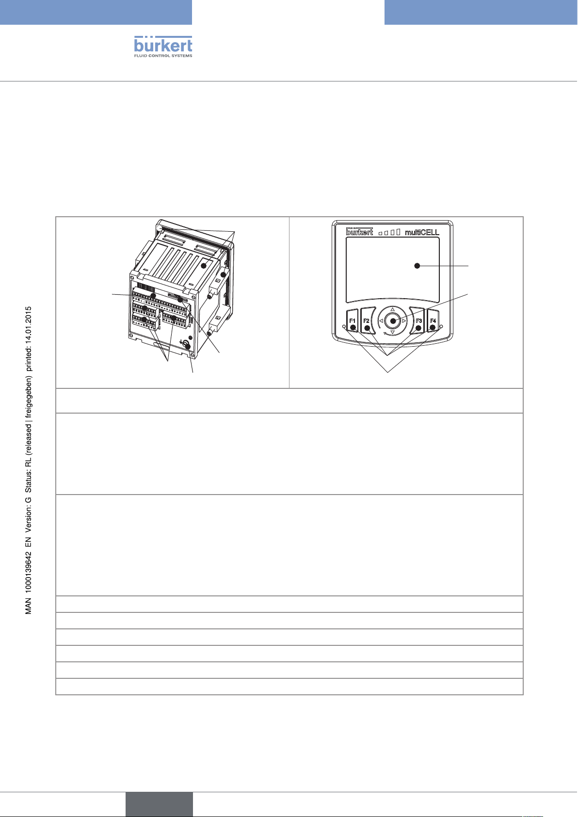
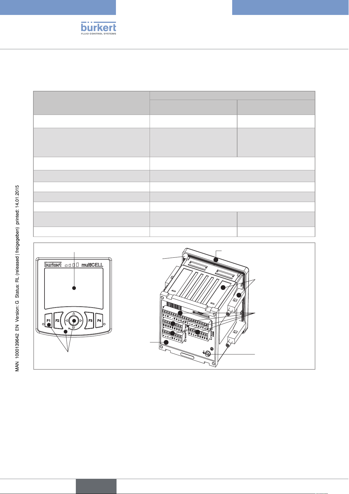
2.2 Construction of a 8619 multiCELL
F
G
E
C
H
J
A: standardised 1/4 DIN housing (92x92 mm) with seal, to be mounted in the door of the electrical enclosure or
cabinet and attached using 4 fasteners.
B: a main board (identified by "M0" on the rear plate):
• To connect the electrical power source of the multiCELL;
• to power another device, e.g. a flow-rate sensor;
• offering 2 digital inputs (identified by "DI", digital input), two 4-20 mA current outputs (identified by "AO",
analogue output) and 2 digital outputs (identified by "DO", digital output).
C: 1 to 6 slots for placing the following connection modules:
• module with light grey connector for connection of a pH sensor or oxidation reduction potential sensor and/or
a temperature sensor
• module with green connector for connection of a conductivity sensor and/or a temperature sensor
• module with black connector with two 4-20 mA current outputs and 2 digital outputs.
• module with orange connector with two analogue inputs and 2 digital inputs.
D: functional earth screw (connected internally to all "FE" terminals on the main board and additional modules).
E: memory card (SD type) reader/recorder
F: display with backlight.
G: navigation button (4 directions).
H: 4 dynamic keys
J: 2 LEDs
Fig. 1 : Construction of a 8619 multiCELL
10
English
Page 13
CB
HJ
G
K
L
N
KLK
L
Type 8619
Product description
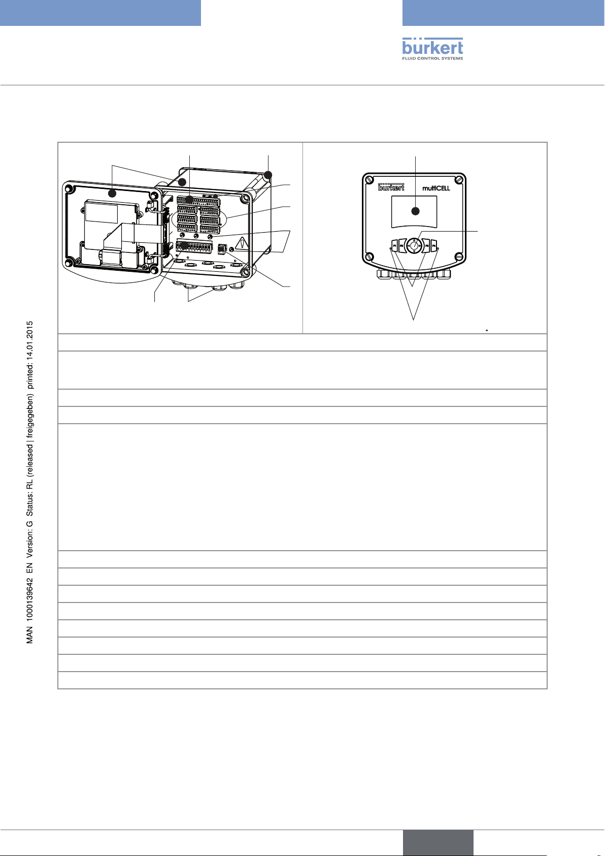
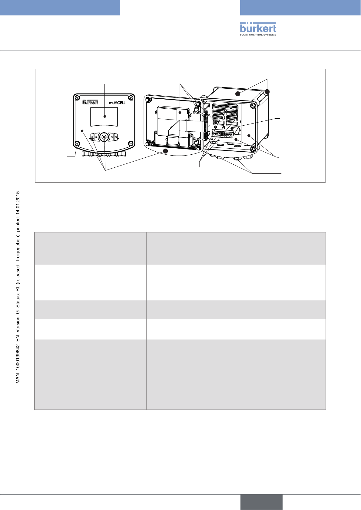
2.3 Construction of a 8619 multiCELL WM DC
A
MEMORY
CARD
M0
M1
M3
M5
FE
PWR OUT
M2
M4
M6
FE
FE
12-36 V
DC
FE
D
E
F
M
A: Wall-mounting housing; Cover with seal, closed by 4 screws; Display with navigation components and LEDs.
B: main board (identified by "M0" on the plate) with two digital inputs (identified by "DI", digital input), two
4-20 mA current outputs (identified by "AO", analogue output) and two digital outputs (identified by "DO", digital
output).
C: Wall-mounting plate, removable
D: memory card (SD type) reader/recorder
E: 6 slots for placing the following connection modules:
• module with light grey connector for connection of a pH sensor or oxidation reduction potential sensor and/or
a temperature sensor;
• module with green connector for connection of a conductivity sensor and/or a temperature sensor;
• module with black connector with two 4-20 mA current outputs and two digital outputs;
• module with orange connector with two analogue inputs and two digital inputs.
If a slot is unused, a cap blanks off the opening
F: functional earth screw (connected internally to all "FE" terminals on the main board and additional modules).
G: Connection terminal board for the 12-36 V DC power supply
H: 5 M20 x 1.5 cable glands
J: supply and distribution board
K: display with backlight.
L: navigation button (4 directions).
M: 4 dynamic keys
N: 2 LEDs
Fig. 2 : Construction of a 8619 multiCELL WM DC
11
English
Page 14
CB
HJ
G
K
L
N
KLK
L
Type 8619
Product description
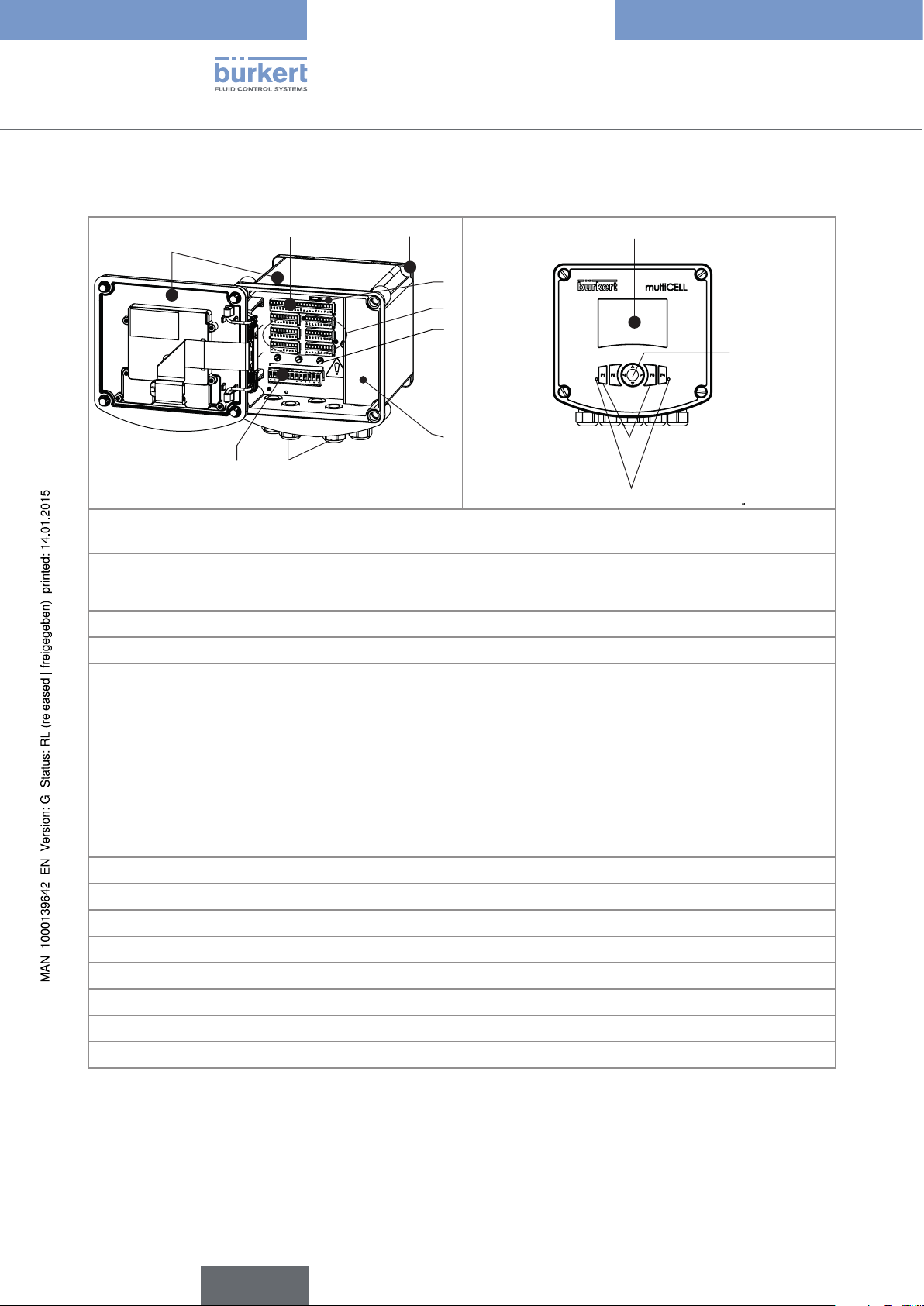
2.4 Construction of a 8619 multiCELL WM AC
A
MEMORY
CARD
M0
M1
M3
M5
PWR OUT
M2
M4
M6
D
E
F
M
A: Wall-mounting housing; Cover with seal, closed by 4 screws; Display with navigation components and LEDs.
B: main board (identified by "M0" on the plate) with two digital inputs (identified by "DI", digital input), two 4-20
mA current outputs (identified by "AO", analogue output) and two digital outputs (identified by "DO", digital
output).
C: Wall-mounting fastening plate, removable
D: Memory card (SD type) reader/recorder
E: 6 slots for placing the following connection modules:
• module with light grey connector for connection of a pH sensor or oxidation reduction potential sensor and/or
a temperature sensor;
12
• module with green connector for connection of a conductivity sensor and/or a temperature sensor;
• module with black connector with two 4-20 mA current outputs and two digital outputs.
• module with orange connector with two analogue inputs and two digital inputs.
If a slot is unused, a cap blanks off the opening
F: functional earth screw (connected internally to all "FE" terminals on the main board and additional modules).
G: Protective cap for the 110-240 V AC power supply terminal board
H: 5 M20 x 1.5 cable glands
J: supply and distribution board
K: display with backlight.
L: navigation button (4 directions).
M: 4 dynamic keys
N: 2 LEDs
Fig. 3 : Construction of a 8619 multiCELL WM AC
English
Page 15
0 %
Type 8619
Product description
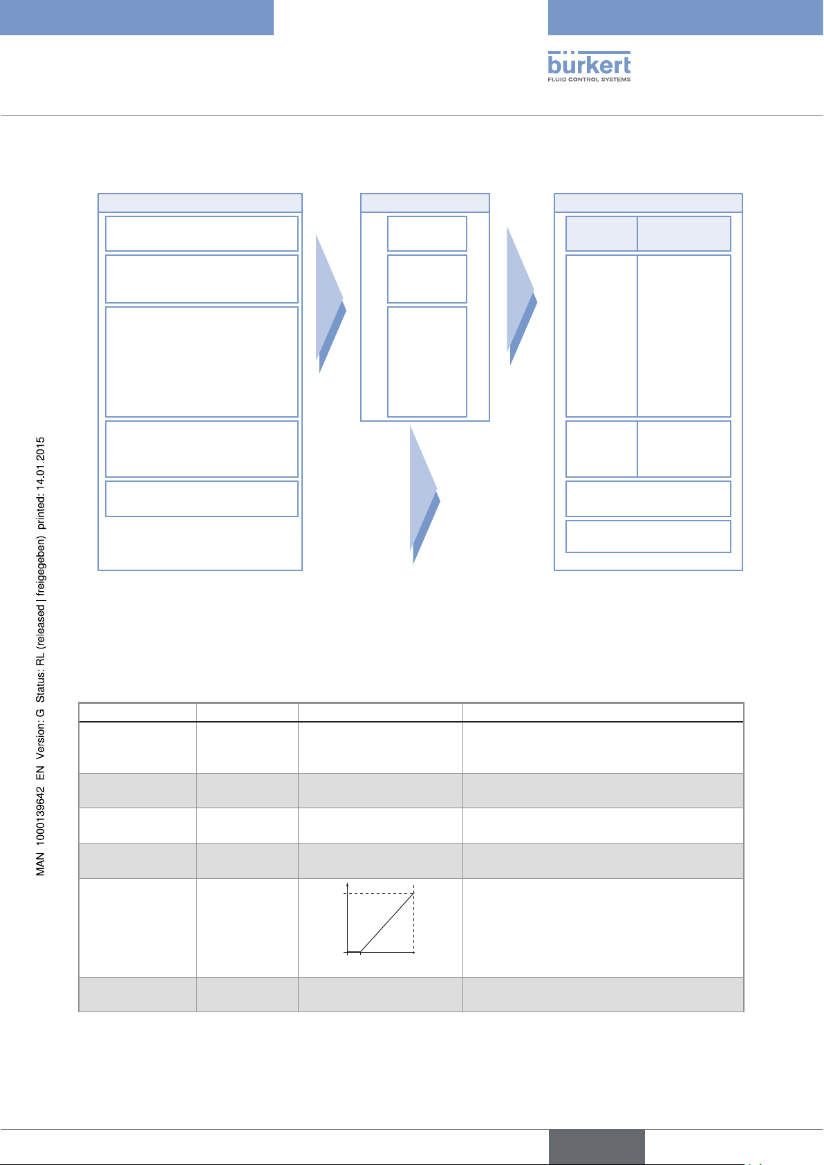
2.5 Functional diagram
INPUTS FUNCTIONS
Digital inputs or frequency
inputs
Analogue inputs, current or
voltage
Conductivity sensor (2 or 4
electrodes)
pH/Redox sensor
Temperature sensor
PT100/PT1000
1)
simultaneously active
1)
OUTPUTS
Function 1 OUTPUT SIGNAL
...
Transistor,
1 and 2
Function 6
4-20 mA,
PWM or on/
off or PFM or
pulse
4-20 mA
1 and 2
Display
Memory card
2.6 Functional description
The multiCELL assigns each input to a function (such as dosing, for example) which is entirely configurable by the
user. According to the model selected, the following are offered as basic or optional functions:
Function Availability Formula Use
Arithmetic Standard on all
models
PASS Standard on all
models
REJECT Standard on all
models
DEVIAT Standard on all
models
PROP
(proportional)
Standard on all
models
ON/OFF Standard on all
models
A+B, A-B, A/B Arithmetic operation between two values
having the same units. A or B may be the
result of another function.
A/B x 100% Calculation of the passage rate.
(1 - A/B) x 100 % Calculation of the rejection rate.
(A/B - 1) x 100 % Calculation of the deviation rate.
100 %
Calculation of an output proportional to a
bounded input.
process
scal- scal+
parameter
ON/OFF control For all input types.
13
English
Page 16
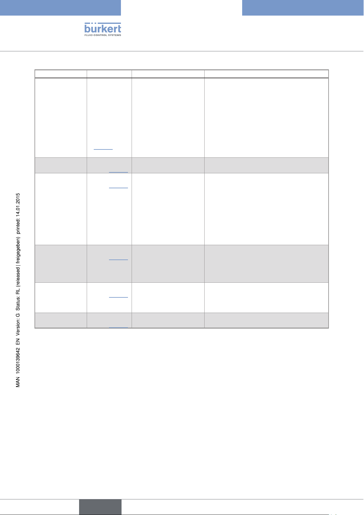
Function Availability Formula Use
Flow rate
measurement
• Standard
on models
Each digital input can be used to measure the
flow rate.
560205,
560213,
565984 à
565987
• Optional
(see section
5.10.4) on all
other models
PID
Time dosing
Optional (see
section 5.10.4)
Optional (see
section 5.10.4)
Continuous regulation For all input types; with internal or external
setpoint.
In a cooling tower, for example; used to dose
2 products at fixed intervals or for twice daily
dosing scheduled over one week.
Type 8619
Product description
Volume dosing
Concentration
Datalogger on
memory card
Optional (see
section 5.10.4)
Optional (see
section 5.10.4)
Optional (see
section 5.10.4)
The time dosing function can be combined
with an ON/OFF function on a conductivity
measurement only, in order to ensure prepurging of the system. The "ON/OFF" function
must be configured and activated before the
time dosing function.
dedicated to the cooling towers. Metering of
a specific volume of water and activation of an
actuator during a specific period in order to
add a product and, finally, reset of the water
volume to zero.
The concentration graphs for certain
compounds such as NaCl and H2SO4
are memorised for use over the entire
concentration range.
Option to memorise the variations in 1 to 16
values in a given time interval.
14
English
Page 17
Type 8619
Product description
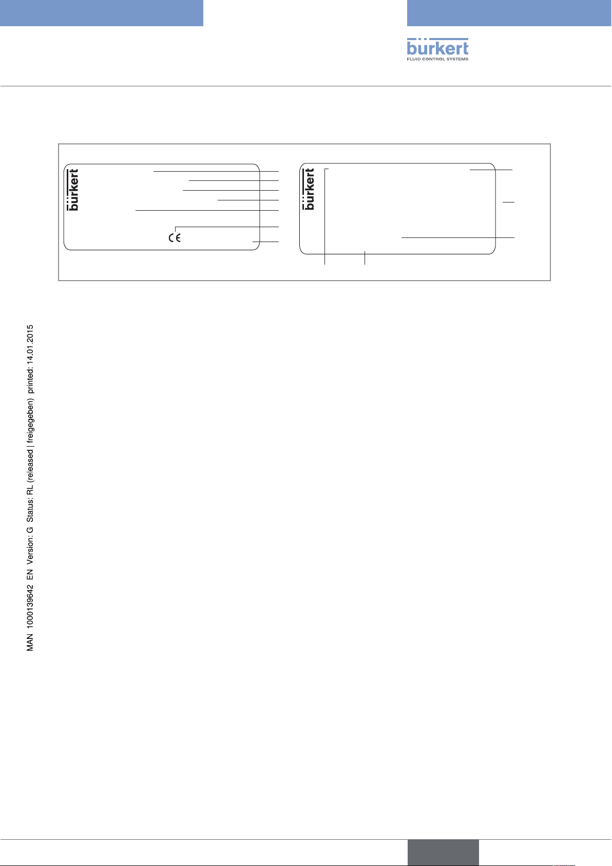
2.7 Description of the name plate
8619 multiCELL
Supply: 12-36V DC, 1.8 A
Temp: -10...+60 °C
IP65 PANEL (FRONT) IP20 (REAR)
Made in France
S-N:1110
00560204
W44ML
Fig. 4 : Example of a name plate
1. Type of device
2. Electrical power supply
3. Ambient temperature range
4. Protection rating
5. Serial number
6. Conformity logo
7. Construction code
8. Device fitted with a memory card reader
1
2
3
4
5
6
7
M0: 2xDI - 2xAO - 2xDO - SD CARD
M1: pH/ORP - PT100/1000
M2: RES COND 2/4 POLES PT100/1000
M3: 2xAO - 2xDO
Made in France
M4:
M5:
M6:
Softw.:
00560204 W44ML
12
11
8
9
}
10
9. Characteristics of the connection modules
10. Software options
11. Order code
12. Properties of the main "M0" board
English
15
Page 18

Type 8619
Product description
16
English
Page 19

Type 8619
Technical data
3 TECHNICAL DATA
3.1 Conditions of use of the 8619 multiCELL ..............................................................................................................18
3.2 Conditions of use of the 8619 multiCELL WM DC ............................................................................................18
3.3 Conditions of use of the 8619 multiCELL WM AC .............................................................................................19
3.4 Compliance to standards and directives ...............................................................................................................19
3.5 Mechanical data ...................................................................................................................................................................20
3.6 Specifications of the "M0" main board of the 8619 multiCELL ..................................................................21
3.7 Specifications of the "M0" main board of the 8619 multiCELL WM .........................................................22
3.8 Specifications of the power supply board of the 8619 multiCELL WM .................................................23
3.9 Specifications of the "POWER OUT" power distribution board for the 8619 multiCELL WM ....24
3.10 Specifications of the "Input" board ...........................................................................................................................24
3.11 Specifications of the memory card reader/recorder ....................................................................................25
3.12 Specifications of the outputs board "OUT" ...........................................................................................................25
3.13 Specifications of the "pH/redox" module ..............................................................................................................26
3.14 Specifications of the "COND" conductivity module .........................................................................................26
English
17
Page 20
Type 8619
Technical data
3.1 Conditions of use of the 8619 multiCELL
Ambient temperature
• without connection module
• with connection module
1)
1)
• -10 to +70 °C
• -10 to +60 °C
Air humidity < 85 %, not condensing
Height above sea level max. 2000 m
Protection rating • IP65, NEMA4X on front, once mounted, and elec-
trical enclosure closed
• IP20 for the parts inside the electrical enclosure
Pollution degree Degree 2 according to UL 61010-1
Category of installation Category 1 according to UL 61010-1
1)
with a memory card available as an accessory (order reference 564072). If a different memory card is used,
observe the operating temperatures given by the manufacturer of the memory card.
3.2 Conditions of use of the 8619 multiCELL WM DC
Ambient temperature
• without connection module
• with connection module
Air humidity < 85 %, not condensing
Height above sea level max. 2000 m
Protection rating IP65, IP67, if the following conditions are met:
1)
1)
• -10 to +75 °C
• -10 to +60 °C
18
• Body of the cable glands tightened with a torque of
5.5 Nm ± 20 % at the factory.
• Cable glands blanked off or wired.
• Screws of the cable glands tightened with a torque
of 4.5 Nm ± 20 %.
• Housing closed.
• The 4 screws for the cover are tightened crosswise
with a torque of 1.4 Nm ± 20 %.
Pollution degree Degree 2 according to UL 61010-1
Category of installation Category I according to UL 61010-1
1)
with a memory card available as an accessory (order reference 564072). If a different memory card is used,
observe the operating temperatures given by the manufacturer of the memory card.
English
Page 21
Type 8619
Technical data
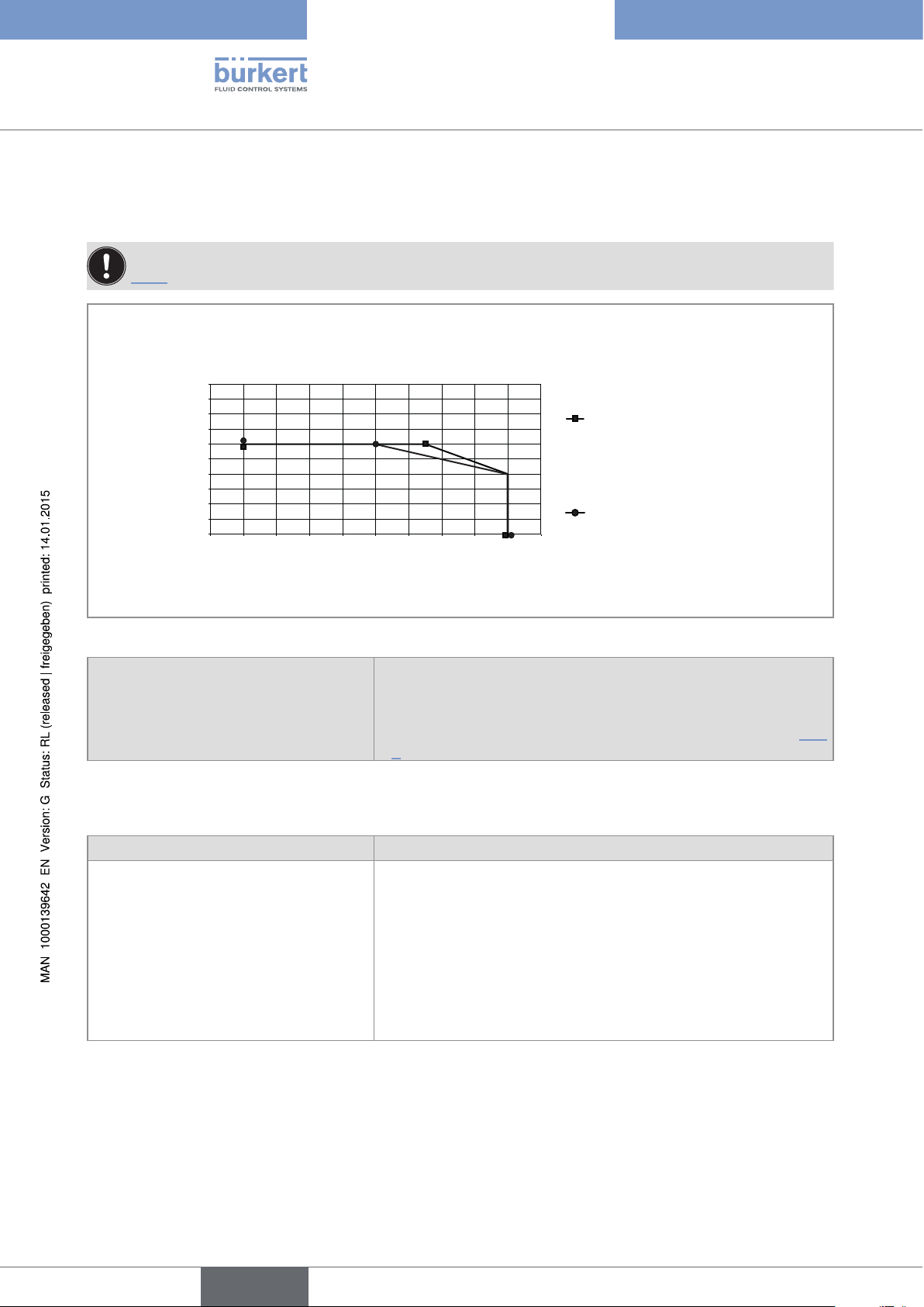
3.3 Conditions of use of the 8619 multiCELL WM AC
Observe the maximum permissible load as a function of the ambient temperature. See the derating curves
Fig. 7, section 3.9.
Ambient temperature -10 to +70 °C
1)
Air humidity < 85 %, not condensing
Height above sea level max. 2000 m
Protection rating, panel-mounting version IP65, IP67, if the following conditions are met:
• Body of the cable glands tightened with a torque of
5.5 Nm ± 20 % at the factory.
• Cable glands blanked off or wired.
• Screws of the cable glands tightened with a torque
of 4.5 Nm ± 20 %.
• Housing closed.
• The 4 screws for the cover are tightened crosswise
with a torque of 1.4 Nm ± 20 %.
Pollution degree Degree 3 according to UL 61010-1 following the con-
ditions below:
• Housing closed.
• The 4 screws for the cover are tightened crosswise
with a torque of 1.4 Nm ± 20 %.
Category of installation Category II according to UL 61010-1
1)
with a memory card available as an accessory (order reference 564072). If a different memory card is used,
observe the operating temperatures given by the manufacturer of the memory card.
3.4 Compliance to standards and directives
The device conforms to the EC directives through the following standards:
• EMC: EN 61000-6-2, EN 61000-6-3
• Resistance to vibrations EN 60068-2-6
• Resistance to shocks: EN 60068-2-27
• For the 8619 multiCELL WM AC: Low voltage directive
The UL devices with command key PE72 (identified by the logo
key PU02 (identified by the logo ), for the United States and Canada, comply with the following
standards:
• UL 61010-1
• CRN/CSA-C22.2 n° 61010-1
) and the UL devices with command
19
English
Page 22
Type 8619
Technical data
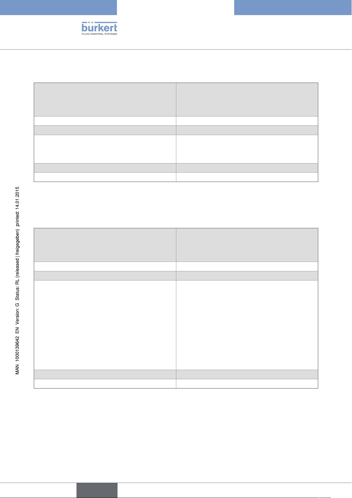
3.5 Mechanical data
Tab. 1 : Materials in contact with the ambient air
Material
Component
8619 multiCELL
Panel-mounting housing and fastener PPO -
Wall-mounting housing, wall-mounting
fastening plate, cable glands, protective cap
(for LCD display), protective blank (for a slot
- PA66
without connection terminal), hinge stiffener.
Seal Silicone
Front panel and keys PC/silicone
Terminal support plate Stainless steel 304
8619 multiCELL WM AC or
8619 multiCELL WM DC
Terminal blocks PBT, contacts in gold-plated copper alloy
Ground screw + spring washer Stainless steel 316 (A4)
Protective cap for the 110-240 V AC power
supply terminal board
- Stainless steel 304
4 cover screws - PVC
PC
Silicone
Stainless steel 304
Silicone
PC
PPO
PBT, contacts in gold-plated
copper alloy
Stainless steel 316 (A4)
20
Fig. 5 : Component materials of the 8619 multiCELL
English
Page 23
Type 8619
Technical data
PC
PVC
Silicone
PA66
PBT, contacts in gold-plated
copper alloy
MEMORY
CARD
M0
M1
M3
M5
1
2
3
45
6
7
PE
PWR OUT
M2
M4
M6
8
9
1
2
3
45
6
7
8
9
PE
PE
Stainless steel 316
(A4)
Stainless steel 304
PA66
Fig. 6 : Component materials of the 8619 multiCELL WM
3.6 Specifications of the "M0" main board of the 8619 multiCELL
Electrical supply 12-36 V DC • filtered and regulated
• SELV circuit, at a non-hazardous energy level
PA66
• Tolerance: ±10 %
Specifications of the 12-36 V DC power
source (not provided) of the UL devices,
• Limited power source (in accordance with section 9.3 of the UL
61010-1 standard)
with variable key PE72
• or class 2 type power source (according to the 1310/1585 and
60950-1 standards)
Own consumption (without connection
1.5 VA
module, outputs not connected)
Power distribution ("PWR OUT") • 12-36 V DC, 1.8 A max.
• Protected against polarity reversal
All digital inputs ("DI") • Switching threshold V
• Switching threshold V
on
off
• Input impedance: 3 kW
• Galvanically isolated
• Protected against polarity reversal and voltage spikes
• Frequency: 0.5 to 2500 Hz
: 5 to 32 V DC
: < 2 V DC
English
21
Page 24

All analogue outputs ("AO") • 4-20 mA current
• Any connection mode, in sink or source mode
• Galvanically isolated
• Protected against polarity reversal
• Max. loop impedance 1100W to 36 V DC, 610W to 24 V DC,
100W to 12 V DC
All digital outputs ("DO") • Transistor
• Any connection mode, in NPN or PNP mode
• Galvanically isolated
• Protected against short circuits
• Max. voltage: 36 V DC
Type 8619
Technical data
• Max. 700 mA per transistor; total of max. 1A if both transistors are
connected
• Max. frequency 2000 Hz
Flow rate measurement Refer to the user operating instructions for the flow sensor con-
nected to the 8619
3.7 Specifications of the "M0" main board of the 8619 multiCELL WM
All digital inputs ("DI") • Switching threshold Von: 5 to 32 V DC
• Switching threshold V
• Input impedance: 3 kW
• Galvanically isolated
• Protected against polarity reversal and voltage spikes
• Frequency: 0.5 to 2500 Hz
All analogue outputs ("AO") • 4-20 mA current
• Any connection mode, in sink or source mode
: < 2 V DC
off
22
• Galvanically isolated
• Protected against polarity reversal
• Max. loop impedance 1100W to 36 V DC, 610W to 24 V DC,
100W to 12 V DC
English
Page 25
Type 8619
Technical data
All digital outputs ("DO") • Transistor
• Any connection mode, in NPN or PNP mode
• Galvanically isolated
• Protected against short circuits
• Max. voltage: 36 V DC
• Max. 700 mA per transistor; total of max. 1A if both transistors are
connected
• Max. frequency 2000 Hz
Flow rate measurement (software option) Refer to the user operating instructions for the flow sensor con-
nected to the 8619
3.8 Specifications of the power supply board of the 8619 multiCELL WM
Electrical supply 12-36 V DC
Maximal consumption
Specifications of the 12-36 V DC power
source (not provided) of the UL devices,
with variable key PU02
Electrical supply 110-240 V AC
• Frequency
• Max. current
• integrated protection
Own consumption (without connection
module, outputs not connected)
• filtered and regulated
• SELV circuit, at a non-hazardous energy level
• Tolerance: ±10 %
• 1.8 A
• Limited power source (in accordance with section 9.3 of the UL
61010-1 standard)
• or class 2 type power source (according to the 1310/1585 and
60950-1 standards)
• 50-60 Hz
• 500 mA
• delayed 3.15 A fuse, 250 V AC, (breaking capacity = 1500 V AC
at 250 V AC)
2 VA
English
23
Page 26
[A]
[°C]
0.8
1.2
1.8
Type 8619
Technical data
3.9 Specifications of the "POWER OUT" power distribution board for the 8619 multiCELL WM
Observe the maximum permissible load as a function of the ambient temperature. See the derating curves
Fig. 7.
Maximum current
of the load
8619 multiCELL WM AC, without
connection module
8619 multiCELL WM AC, with
0
-10 +100 +20 +30 +40 +50 +60 +70 +80
connection module
Ambient temperature
Fig. 7 : Derating curves of the maximum permissible current, depending on the ambient temperature
Power distribution
• 12-36 V DC version
• 110-240 V AC version
Protected against polarity reversal
• 12-36 V DC, 1.8 A max.
• 24 V DC, filtered and regulated, 1,2 A max.: see the curves in Fig.
7. SELV circuit, at a non-hazardous energy level
3.10 Specifications of the "Input" board
Power consumption 0.1 VA
Digital inputs ("DI") • Switching threshold V
• Switching threshold V
• Input impedance: 3 kW
• Galvanically isolated
• Protected against polarity reversal and voltage spikes
• Frequency: 0.5 to 2500 Hz
: 5 to 32 V DC
on
: < 2 V DC
off
24
English
Page 27

Type 8619
Technical data
Analogue inputs ("AI") • Any connection mode, in sink or source mode
• Galvanically isolated
• Precision ±0.25 %
• Current: 0 - 22 mA or 3.5 - 22 mA. Max. voltage: 36 V DC.
Impedance: 50 W. Resolution: 1.5 µA
• Voltage: 0 - 5 V DC or 0 - 10 V DC. Max. voltage: 36 V DC.
Impedance: 110 kW. Resolution: 1 mV
3.11 Specifications of the memory card reader/recorder
• Memory card type
• Capacity
• File system
• SD (Secure Digital) or SDHC (Secure Digital High Capacity)
• 8 GB max.
• FAT32
3.12 Specifications of the outputs board "OUT"
Power consumption 0.1VA
All digital outputs ("DOx") • Transistor
• Any connection mode, in NPN or PNP mode
• Galvanically isolated
• Protected against short circuits
• Max. voltage: 36 V DC
• Max. 700 mA per transistor; total of max. 1A if both transistors are
connected
• Max. frequency 2000 Hz
All analogue outputs ("AOx") • 4-20 mA current
• Any connection mode, in sink or source mode
• Galvanically isolated
• Protected against polarity reversal
• Max. loop impedance 1100W to 36 V DC, 610W to 24 V DC,
100W to 12 V DC
English
25
Page 28

Type 8619
Technical data
3.13 Specifications of the "pH/redox" module
pH measurement
• pH measurement range
• Resolution of pH measurement
• Systematic variation in the pH
measurement
• Potential difference measurement range
• Resolution of the potential difference
measurement
• Systematic variation in the potential difference measurement
• pH probe type
Power consumption 0.1VA
Measurement of the oxidation reduction
potential
• Oxidation reduction potential measurement
range
• Resolution of the potential difference
measurement
• Systematic variation in the potential difference measurement
• -2.00...+16.00 pH
• 0.01pH
• ±0.02 pH + pH probe error
• -600...+600 mV
• 0.1 mV
• ±1 mV + pH probe error
• Electrochemical
• -2000 ... +2000 mV
• 0.1 mV
• ±1 mV + ORP probe error
26
• Oxidation reduction potential probe type
Temperature measurement
• Measurement range
• Measurement resolution
• Systematic variation in the measurement
• Temperature sensor type
• Electrochemical
• -25 °C ... +130 °C
• 0.1 °C
• ±1 °C + temperature probe error
• Pt100 or Pt1000, with 2 or 3 wires
3.14 Specifications of the "COND" conductivity module
Resistance measurement (without
conductivity sensor connected)
Power consumption 0.25VA
Conductivity cell type With 2 or 4 electrodes; the specifications of Bürkert cells are
5 W ... 1 MW
described in the related operating instructions.
English
Page 29
Type 8619
Technical data
Conductivity measurement (with
connected conductivity sensor)
• Measurement range
• Measurement resolution
• Systematic variation in the measurement
Resistivity measurement (with connected
conductivity sensor)
• Measurement range
• Measurement resolution
• Systematic variation in the measurement
(without sensor)
Temperature measurement
• Measurement range
• Measurement resolution
• Systematic variation in the measurement
• Temperature sensor type
• 0.000 µS/cm ... 2 S/cm (depends on the conductivity sensor)
-9
• 10
S/cm
• ±0.5% of the measured value + conductivity sensor error
• 0.500 W.cm ... 100 MW.cm (depends on the conductivity
sensor)
-1
• 10
W.cm
• ±0.5% of the measured value + conductivity sensor error
• -40 °C ... ±200 °C
• ±0.1 °C
• ±1 °C + temperature probe error
• Pt100 or Pt1000, with 2 or 3 wires
English
27
Page 30

Type 8619
Technical data
28
English
Page 31

Type 8619
Installation and wiring
4 INSTALLATION AND WIRING
4.1 Safety instructions .............................................................................................................................................................30
4.2 Installation procedure ......................................................................................................................................................31
4.2.1 Installing a 8619 multiCELL on an enclosure or electrical cabinet ........................................31
4.2.2 Installing a 8619 multiCELL WM on a support ...........................................................................32
4.3 Electrical wiring ....................................................................................................................................................................34
4.3.1 Recommendations for wiring a 8619 multiCELL WM ...............................................................34
4.3.2 Specifications of the connection cables .......................................................................................34
4.3.3 Wiring the 12-36 V DC electrical supply for a 8619 multiCELL ............................................35
4.3.4 Wiring the 12-36 V DC electrical supply for a 8619 multiCELL WM DC ...........................36
4.3.5 Wiring the 110-240 V AC electrical supply for a 8619 multiCELL WM AC ......................36
4.3.6 Supplying an external instrument via a 8619 multiCELL .......................................................... 37
4.3.7 Supplying an external instrument via a 8619 multiCELL WM .................................................38
4.3.8 Wire the inputs and outputs on the main board "M0" ...............................................................38
4.3.9 Examples of the connection of flowmeters to a 8619 multiCELL ...........................................40
4.3.10 Examples of the connection of a solenoid valve to a 8619 multiCELL WM ........................41
4.3.11 Identifying the pins on the connection modules ..........................................................................41
4.3.12 Wiring the input module "INPUT" ...................................................................................................42
4.3.13 An example of the connection of a type 8232 chlorine sensor (order code
566051 or 566052) to the input module "INPUT". ...................................................................44
4.3.14 An example of the connection of a type 8232 chlorine sensor (order code
565164) to the input module "INPUT". .........................................................................................44
4.3.15 Wiring the output module "OUT"....................................................................................................46
4.3.16 Wiring the "pH/ORP" module .........................................................................................................47
4.3.17 Examples of connection to be "pH/ORP" module ......................................................................48
4.3.18 Wiring the "COND" conductivity module .....................................................................................49
4.3.19 Examples of connection to the "COND" conductivity module .................................................50
English
29
Page 32

Type 8619
Installation and wiring
4.1 Safety instructions
DANGER
Risk of injury due to electrical voltage.
▶ If a 12-36 V DC version is installed either in a wet environment or outdoors, all the electrical voltages must be
of max. 35 V DC.
▶ Disconnect the electrical power for all the conductors and isolate it before carrying out work on the system.
▶ All equipment connected to the 8619 shall be double insulated with respect to the mains according to the
standard IEC 61010-1:2010.
▶ Observe all applicable accident protection and safety regulations for electrical equipment.
WARNiNG
Risk of injury due to nonconforming installation.
▶ Electrical installation can only be carried out by qualified and authorised personnel with the appropriate tools.
▶ Fit a circuit breaker or switch to the electrical installation of the building in which the device is installed.
▶ Install the circuit breaker or switch in an easily accessible place.
▶ Identify the circuit breaker or switch as the disconnecting component for the electrical power supply to the
device.
▶ Install appropriate safety devices (correctly rated fuse and/or circuit-breaker).
▶ For a version powered by 110-240 V AC, insert an overload device between the live and the neutral.
▶ Do not power the 24 V DC version of the device with an AC voltage or with a DC voltage higher than
36V DC.
▶ Do not power the 100-240 V AC version with a DC voltage or with an AC voltage higher than 240 V AC.
▶ Observe standard NF C 15-100 / IEC 60634.
▶ The use of probes/sensors sold by Bürkert is preferable.
▶ Follow the instructions for installation and wiring of remote sensors connected to the 8619.
▶ On a 8619 multiCELL WM, only authorized personnel may insert in or remove the memory card from the
reader/recorder.
Risk of injury due to unintentional switch on of power supply or uncontrolled restarting of the
installation.
▶ Avoid unintentional activation of the installation.
▶ Guarantee a set or controlled restart of the process subsequent to the installation of the device.
30
Protect this device against electromagnetic interference, ultraviolet rays and, when installed outdoors, the effects of the climatic conditions.
Make sure the installation inputs are transformed-coupled for galvanic isolation.
English
Page 33

Type 8619
Installation and wiring
4.2 Installation procedure
1. To carry out mechanical installation: Depending on the version, follow the instructions in section 4.2.1 or 4.2.2.
2. To wire the device: Depending on the version, follow the instructions in section 4.3.
4.2.1 Installing a 8619 multiCELL on an enclosure or electrical cabinet
Follow the instructions below to mount the 8619, delivered fully assembled, onto an enclosure or cabinet.
→
92 +0,5/-0
5
5,55,5
92 +0,5/-0
10
This diagram is not to scale. The dimensions are given
in mm.
Body
x4
Screw
Step 1:
→ Check that the thickness of the door of the enclosure
or cabinet is no more than 4 mm.
→ Ensure there will be sufficient space around the cut
out hole and on the inside of the cabinet to easily
accommodate the 4 fasteners.
→ Cut a hole in the door of the enclosure or electrical
cabinet according to standard CEI 61554:1999 (DIN
43700).
Step 2:
Prepare the 4 fasteners:
→ Insert a screw into each device.
→ Tighten the screw until the end of the shaft of the
screw is flush with the device.
Step 3:
→ Slide the housing into the cut-out with the connectors
to the back, until it can go no further.
Step 4:
→ Insert (1) the hooks on the first fastener into the slots
on the housing.
1
→ Pull the fastener (2).
2
31
English
Page 34

Risk of material damage the cable glands are loosened. The body of the cable glands are screwed into
the housing at the factory with a torque of 5.5 Nm
Type 8619
Installation and wiring
Step 5:
→ Place the fastener flush against the 8619 by hand,
so that the hooks remain in place.
Step 6:
→ Fully tighten the screws using an appropriate
screwdriver.
→ Repeat steps 4 to 6 to fit the remaining 3 fasteners.
Fig. 8 : Panel mounting of the 8619 on an enclosure or cabinet
4.2.2 Installing a 8619 multiCELL WM on a support
NOTE
▶Before installing the wall-mounting housing on its support, check that the bodies of the cable glands are tight-
ened. If the bodies of the cable glands are loose, tighten them with a torque of 5.5 Nm ± 20 %.
The 8619 multiCELL WM is installed on a support using the wall-mounting fastening plate.
→ Choose a location such that:
• The surface is plane.
• The surface temperature of the support remains below 100 °C.
• The display is at eye level.
• There is sufficient space to open the housing by 180°.
32
English
Page 35

135
90
Type 8619
Installation and wiring
3
2
Step 1: Removing the wall-mounting fastening plate
from the device.
1. Press the tab to unlock the device.
2. Lift the device.
3. Separate the device from the wall-mounting fastening plate.
1
Step 2: Installing the wall-mounting fastening plate on
the support.
The screws and washers are not provided.
→ Drill holes in the support according to the dimensions
indicated on the diagram to the left.
→ Use 4 screws of 6 mm diameter, which will support the
weight of the device and are suitable for the support.
→ Insert a washer for each screw.
→ Insert the 4 screws in the wall-mounting fastening
plate and in the holes drilled in the support.
This diagram is not to scale. The dimensions are given
in mm.
runners
slides
1
2
→ Tighten the 4 screws in a crosswise manner, with a
maximum torque of 5.3 Nm.
Step 3: Installing the device on the fastening plate.
→ Align the base of the slides with the height of the
runners.
→ Insert the 4 slides into the 4 runners until you hear
a click.
Fig. 9 : Installation of a 8619 multiCELL WM on a support
33
English
Page 36

Type 8619
Installation and wiring
4.3 Electrical wiring
DANGER
Risk of injury due to electrical voltage.
▶ If a 12-36 V DC version is installed either in a wet environment or outdoors, all the electrical voltages must be
of max. 35 V DC.
▶ Disconnect the electrical power for all the conductors and isolate it before carrying out work on the system.
▶ All equipment connected to the 8619 shall be double insulated with respect to the mains according to the
standard IEC 61010-1:2010.
▶ Observe all applicable accident protection and safety regulations for electrical equipment.
4.3.1 Recommendations for wiring a 8619 multiCELL WM
NOTE
On a 8619 multiCELL WM, the ribbon cable which connects the display to the electronic board can be
damaged.
▶ Open and close the cover of the housing with care.
▶ Do not pinch the ribbon cable.
▶ Do not pull the ribbon cable.
▶ Manipulate the ribbon cable with care.
▶ If the ribbon cable is disconnected, reconnect it with care.
NOTE
A 8619 multiCELL WM may be damaged if the device is not tight.
▶ Make sure the nuts of the unused cable glands are tightened (at the factory, a stopper gasket has been
inserted in each cable gland).
▶ When the mechanical installation and wiring are completed, tighten the cable gland screws with a torque of
4.5 Nm ± 20 %.
▶ When the mechanical installation and wiring are completed, tighten the 4 screws of the cover in a crosswise
manner with a torque of 1.4 Nm ± 20 %.
→ Before wiring the device, install it according to the instructions in section 4.2.1 or section 4.2.2.
4.3.2 Specifications of the connection cables
The electrical connections are carried out via terminal blocks:
34
• Directly, on a 8619 multiCELL.
• Via the cable glands, on a 8619 multiCELL WM.
→ Use shielded cables (not provided) with a maximum operating temperature greater than 80 °C.
→ Use cables and electric wires with dimensions that adhere to the specifications described in Tab. 2.
English
Page 37

Type 8619
Installation and wiring
Tab. 2 : Specifications of the cables and conductors
External diameter of the cable (8619 multiCELL WM) 6 to 12 mm (4 mm if using multiply drilled seals)
Cross-section of the local earth connection conductor
0.75 ... 1.5 mm
2
(12-36 V DC versions)
Rigid conductor cross-section H05(07) V-U 0.2 ... 1.5 mm2, stripped over 7 mm
2
Flexible conductor cross-section H05(07) V-K 0.2 ... 1.5 mm
Cross-section of a conductor with a non-insulated lug 0.2 ... 1.5 mm
Cross-section of a conductor with an insulated lug 0.2 ... 0.75 mm
, stripped over 7 mm
2
, stripped over 7 mm
2
, stripped over 7 mm
4.3.3 Wiring the 12-36 V DC electrical supply for a 8619 multiCELL
Use a filtered and regulated 12-36 V DC electrical power supply.
→
→ Wire the 12-36 V DC power supply on the "M0" terminal board of a 8619 multiCELL.
→ Connect the functional earth of the installation to the earth screw of the device (see section 2.2, Fig. 1) using
a lug with an eyelet, suitable for the M4 earth screw and earth conductor. Tighten with a torque of 1 Nm ±
20 %.
→ Connect the shielding on each wire to an "FE" (functional earth) terminal to guarantee the equipotentiality of
the installation.
12-36 VDC
+
Electrical power supply
-
+
V-
FE
V+
SUPPLY PWR OUT DI1 FEDI2 DO2DO1AO1 AO2 FE FE
FE
D+D-D+
Removable screw terminals, 21-positions, orange
Fig. 10 : Wiring the 12-36 V DC electrical supply for a 8619 multiCELL
D-
FE
I+I-I+
I-
FE
T+T-T+
T-
FE
English
35
Page 38

Type 8619
Installation and wiring
4.3.4 Wiring the 12-36 V DC electrical supply for a 8619 multiCELL WM DC
Use a filtered and regulated 12-36 V DC electrical power supply.
→
→ Use the rightmost cable gland for the electrical power supply cable.
→ Wire the 12-36 V DC power supply for a 8619 multiCELL WM on a terminal block marked 12-36 V DC.
→ Connect the functional earth of the installation to the earth screw of the device (see section2.3, Fig. 2)
using a lug with an eyelet, suitable for the M4 earth screw and earth conductor. Tighten with a torque of
1 Nm ± 20 %.
→ Connect the shielding on each wire to an "FE" (functional earth) terminal to guarantee the equipotentiality of
the installation.
Removable screw
terminals, 2-positions,
green
12-36 V
MEMORY
CARD
M0
M1
M3
M5
FE
FE
PWR OUT
M2
M4
M6
FE
12-36 V
DC
FE
DC
+
-
FE
12-36 VDC
-
Electrical power supply
+
Fig. 11 : Wiring the 12-36 V DC electrical supply for a 8619 multiCELL WM
4.3.5 Wiring the 110-240 V AC electrical supply for a
8619 multiCELL WM AC
→ Unscrew and remove the
MEMORY
CARD
M0
M1
M3
M5
PE
PWR OUT
M2
M4
M6
PE
PE
protective cover of the power
supply connection terminal
block.
36
Protective cover
English
Page 39

L
Type 8619
Installation and wiring
Removable screw
terminals, 2-positions,
green
110-240 V~
50/60 Hz
L
N
PE
N
PE
Fig. 12 : Wiring the 110-240 V AC electrical supply for a 8619 multiCELL WM AC
PE
110-240 V~
50/60 Hz
LN
→ Use the rightmost cable
gland for the electrical power
supply cable.
→ Wire the 110-240 V AC
power supply for a
8619 multiCELL WM AC
on a terminal block marked
110-240 V AC.
→ Connect the protective earth
of the installation to the earth
screw of the device (see
section2.4, Fig. 3) using a
lug with an eyelet, suitable for
the M4 earth screw and earth
conductor. Tighten with a
torque of 1 Nm ± 20 %.
L: Live conductor
N: Neutral conductor
→ Put in place and screw on the
protective cover.
4.3.6 Supplying an external instrument via a 8619 multiCELL
The device can be used to supply an external instrument, for example a flow sensor, with a voltage identical to the
supply voltage of the 8619
The power supply is available on the "M0" terminal block of a 8619 multiCELL.
12-36 VDC
+
Electrical power supply
V-
FE
V+
SUPPLY PWR OUT DI1 FEDI2 DO2DO1AO1 AO2 FE FE
Removable screw terminals, 21-positions, orange
Fig. 13 : Supplying an external instrument via a 8619 multiCELL
Power supply available for an
external instrument
{
-
+
FE
D+D-D+
D-
FE
I+I-I+
I-
FE
T+T-T+
T-
FE
37
English
Page 40

POWER OUT
Type 8619
Installation and wiring
4.3.7 Supplying an external instrument via a 8619 multiCELL WM
The device can be used to supply power to several external instruments, such as flow sensors or conductivity
sensors for example.
→ To supply power to an external instrument, connect it to a positive and negative terminal on the POWER OUT
terminal block.
The voltage available on the POWER OUT terminal block of a 8619 multiCELL WM:
• is equal to the supply voltage of the 8619 multiCELL WM DC which is supplied with a voltage of 12-36 V DC.
• is equal to a voltage of 24 V DC on a 8619 multiCELL WM AC which is supplied with a voltage of
110-240 V AC.
+ -+- + - + -+- + -
Removable screw terminals,
12-positions, green
Fig. 14 : Supplying external instruments via a 8619 multiCELL WM
4.3.8 Wire the inputs and outputs on the main board "M0"
The M0 board has:
• 2 digital inputs (marked DI1 and DI2), for connecting a flow sensor for example
• Two 4-20 mA analogue outputs (marked AO1 and AO2)
• 2 digital outputs (marked DO1 and DO2)
The inputs and outputs are galvanically insulated and therefore floating.
38
English
Page 41

5-36 VDC
Type 8619
Installation and wiring
1st 4-20 mA input (at
external instrument)
+-
0 VDC
1st digital output (at exter-
nal instrument)
Removable screw ter-
minals, 21-positions,
2nd digital output (at
external instrument)
orange
-
+
0 VDC
5-36 VDC
0 VDC
D-
D+D-D+
DI1 FEDI2 DO2DO1AO1 AO2 FE FE
FE
digital inputs digital
12-36 VDC
12-36 VDC
I+I-I+
analogue
outputs
0 VDC
I-
FE
12-36 VDC
T+T-T+
outputs
+-
2nd 4-20 mA input (at
external instrument)
Load 1
+
-
0 VDC
12-36 VDC
+
-
0 VDC
Load 2
T-
FE
DI1, DI2, AO1, AO2, DO1 and DO2: designation in the configuration menus of the M0 main board.
FE = functional earth
Fig. 15 : Wiring the inputs and outputs on the main board "M0"
39
English
Page 42

Type 8619
Installation and wiring
4.3.9 Examples of the connection of flowmeters to a
8619 multiCELL
PNP
1
1
V+
12-36 VDC
3
+
Electrical power
supply
Removable screw
terminals, 21-posi-
tions, orange
V-
V+
SUPPLY PWR OUT DI1 FEDI2 DO2DO1AO1 AO2 FE FE
Fig. 16 : Wiring the 2 type 8030 flow sensors
8071
FE
-
+
FE
X
0V
D+D-D+
2
D-
NPN
FE
I+I-I+
V+
I-
3
FE
T+T-T+
0V
2
FE = functional earth
T-
FE
8041
4...20V+V-PEPls+Pls-
40
VDC
Red
Black
White
12-36 VDC
+
Electrical power
supply
Removable screw
terminals, 21-posi-
V-
tions, orange
Fig. 17 : Wiring a type 8071 flow sensor and a type 8041 flow sensor
V+
SUPPLY PWR OUT DI1 FEDI2 DO2DO1AO1 AO2 FE FE
FE
-
+
FE
D+D-D+
D-
FE
I+I-I+
I-
FE
T+T-T+
1 2 3 4 5 6
FE = functional earth
T-
FE
English
Page 43

12-36 VDC
Type 8619
Installation and wiring
4.3.10 Examples of the connection of a solenoid valve to a 8619 multiCELL WM
The solenoid valve can be connected to the device via board "M0" or via the outputs module, "OUT".
→ If a solenoid valve is connected to the device, connect a flyback diode in parallel to the solenoid valve. If the
solenoid valve is connected via a type 2508 connector, this connector is available with an integrated flyback
diode.
Solenoid valve
+
-
Removable screw terminals, 21-positions, orange
0 VDC
D+D-D+
DI1 FEDI2 DO2DO1AO1 AO2 FE FE
Fig. 18 : Wiring a solenoid valve to the "M0" board of the 8619
D-
FE
I+I-I+
I-
FE
T+T-T+
T-
FE
4.3.11 Identifying the pins on the connection modules
If you use terminal blocks other than those supplied with the device, these terminal blocks will not be marked.
Fig. 19 enables labelling of the terminals.
MEMORY CARD
M0
NC DI1 DI2 FE AO1 AO2 FE DO1 DO2 FE
M1
M2
M3
M5
Fig. 19 : Identifying the pins on the connection modules
M4
M6
Terminal No. 9Terminal No. 1
41
English
Page 44

4.3.12 Wiring the input module "INPUT"
The "INPUT" inputs module has:
• Two analogue inputs;
• Two digital inputs.
The inputs are galvanically insulated, and therefore floating.
1st 0/4-20 mA output (at
+-
external instrument)
0 VDC
2nd 0/4-20 mA output (at external instrument)
Type 8619
Installation and wiring
Removable screw termi-
nals, 9-positions, orange
+-
12-36 VDC
12-36 VDC
A+A-A+
1
2 3 4 5 6 7 8 9
(AI1) (AI2) (DI1) (DI2)
0 VDC
A-
FE
5-36 VDC
0 VDC
D+D-D+
5-36 VDC
1st digital output (at
external instrument)
+
-
0 VDC
D-
2nd digital output (at
external instrument)
(designation in the configuration menus of the Mx
additional output module)
42
digital inputsanalogue
inputs
FE = functional earth
Fig. 20 : Connecting the analogue inputs to a 2-wire current transmitter and connecting the digital inputs of the input
module
English
Page 45

Type 8619
Installation and wiring
1st 0/4-20 mA output
(at external instrument)
12-36 VDC
0 VDC
Removable screw termi-
nals, 9-positions, orange
+-
I
12-36 VDC
A+A-A+
1
2 3 4 5 6 7 8 9
A-
FE
(AI1) (AI2) (DI1) (DI2)
digital inputsanalogue
inputs
+-
0 VDC
12-36 VDC
D+D-D+
2nd 0/4-20 mA output
(at external instrument)
I
1st digital output (at
external instrument)
0 VDC
+
-
12-36 VDC
+
-
2nd digital output (at
external instrument)
0 VDC
D-
(designation in the configuration menus of the Mx
additional output module)
FE = functional earth
Fig. 21 : Connecting the AI1 analogue input in source mode and the analogue input AI2 in sinking mode to a 3-wire
current transmitter (for example type 8025 with relay outputs) and connecting the digital inputs of the input module
1st 0-5/10 V DC output
(external instrument)
+-
V
0 VDC
+
-
1st digital output (at
external instrument)
12-36 VDC
12-36 VDC
0 VDC
12-36 VDC
+
-
2nd digital output (at
external instrument)
0 VDC
Removable screw termi-
nals, 9-positions, orange
A+A-A+
1
2 3 4 5 6 7 8 9
(AI1) (AI2) (DI1) (DI2)
A-
FE
D+D-D+
D-
(designation in the configuration menus of the Mx
additional output module)
digital inputsanalogue
inputs
FE = functional earth
Fig. 22 : Connecting the analogue inputs to a voltage transmitter and connecting the digital inputs of the input module
English
43
Page 46

89
(AI1) (AI2) (DI1) (DI2)
89
(AI1) (AI2) (DI1) (DI2)
Type 8619
Installation and wiring
4.3.13 An example of the connection of a type 8232 chlorine
sensor (order code 566051 or 566052) to the input module
"INPUT".
Electrical supply to the
chlorine sensor
12-36 VDC
+-
+-
Removable screw
terminals, 9-positions,
orange
A+A-A+
1
2345 67
A-
FE
D+D-D+
D-
"INPUT" module of the 8619
Electrical supply to the
chlorine sensor
12-36 VDC
+-
+-
Removable screw
terminals, 9-positions,
orange
A+A-A+
1
2345 67
A-
FE
D+D-D+
D-
"INPUT" module of the 8619
FE = functional earth
Fig. 23 : Possible connections of a type 8232 chlorine sensor (order code 566051 or 566052) powered by an external
voltage source
44
4.3.14 An example of the connection of a type 8232 chlorine
sensor (order code 565164) to the input module "INPUT".
NOTE
The type 8232 chlorine sensor may be damaged by the electrical power supply.
▶ Power the chlorine sensor with a voltage between 22.5 and 26 V DC.
▶ If the chlorine sensor is powered via a type 8619, power the type 8619, 12-36 V DC version, with a power
supply between 22.5 and 26 V DC.
Colour of the conductor for chlorine sensor (order code 565164) Signal
Green Negative voltage signal
Yellow Positive voltage signal
White Positive supply
Brown Negative supply
English
Page 47

89
(AI1) (AI2) (DI1) (DI2)
Type 8619
Installation and wiring
22.5-26 VDC
Electrical power supply of the 8619
+
White
M0: Removable screw terminal,
21-positions, orange
-
+
V-
FE
V+
SUPPLY PWR OUT DI1 FEDI2 DO2DO1AO1 AO2 FE FE
FE
D+D-D+
D-
I+I-I+
FE
I-
FE
T+T-T+
T-
Brown
Green
Yellow
Removable screw
terminals, 9-positions,
orange
A+A-A+
1
2345 67
A-
FE
D+D-D+
FE
D-
"INPUT" module of the
8619
FE = functional earth
Fig. 24 : Connection of the type 8232 chlorine sensor (order code 565164), powered via the 8619 multiCELL
45
English
Page 48

4.3.15 Wiring the output module "OUT"
The "OUT" outputs module has:
• Two 4-20 mA analogue outputs;
• Two digital outputs.
The outputs are galvanically insulated, and therefore floating.
Type 8619
Installation and wiring
1st 4-20 mA
input (at external
instrument)
+-
0 VDC
12-36 VDC
Removable screw termi-
nals, 9-positions, orange
I+I-I+
1
(AO1) (AO2) (DO1) (DO2)
FE = functional earth
Fig. 25 : Wiring the "OUT" output module
12-36 VDC
12-36 VDC
0 VDC
I-
FE
T+T-T+
2 3 4 5 6 7 8 9
digital outputsanalogue outputs
2nd 4-20 mA input (at
+-
external instrument)
Load 1
+
0 VDC
12-36 VDC
0 VDC
-
+
-
Load 2
T-
(designation in the configuration menus of the Mx
output module)
46
English
Page 49

Type 8619
Installation and wiring
4.3.16 Wiring the "pH/ORP" module
• To avoid the influence of disturbances, wire the pH/redox sensor in symmetric mode. In this case, it is
compulsory to wire the equipotential electrode.
• When the pH/redox sensor is wired in asymmetrical mode, measurement of the pH or the oxidation
reduction potential may drift over time when the equipotential electrode is not wired.
Temperature sensor
Oxidation reduction potential
measurement electrode
Reference electrode
Strap (not delivered)
FE
RE
RE
ME
1 2 3 4 5 6 7 8 9
GD
CG
SE
TS
FE = functional earth
TS
Removable screw terminals,
9-positions, grey
Fig. 26 : Wiring an oxidation reduction potential sensor and a Pt100 or Pt1000 temperature sensor in a pH/ORP module
Oxidation reduction potential meas-
urement electrode
Temperature sensor
Reference electrode
pH measurement
electrode
FE
TS
RE
RE
ME
1 2 3 4 5 6 7 8 9
GD
CG
SE
TS
Removable screw terminals,
9-positions, grey
FE = functional earth
Fig. 27 : Wiring a pH sensor, an oxidation reduction potential sensor and a Pt100 or Pt1000 temperature sensor in a pH/
ORP module
English
47
Page 50

Black
Type 8619
Installation and wiring
(1)
(1)
Temperature sensor
Reference electrode
Translucent
Equipotential electrode
pH measurement electrode
Strap (not delivered)
FE
TS
RE
RE
ME
1 2 3 4 5 6 7 8 9
GD
CG
SE
TS
Removable screw terminals, 9-positions, grey
FE = functional earth
(1)
Colour of the wires in Bürkert connection cables with order codes 561904, 561905 or 561906.
Fig. 28 : Wiring a pH sensor and a Pt100 or Pt1000 temperature sensor in asymmetrical mode to a pH/ORP module
4.3.17 Examples of connection to be "pH/ORP" module
(1)
Black
Equipotential electrode
48
(1)
Temperature sensor
Reference electrode
CG
(2)
Brown
FE
(2)
White
SE
TS
(2)
Black
TS
pH measurement electrode
Translucent
(2)
Blue
RE
RE
ME
1 2 3 4 5 6 7 8 9
GD
Removable screw terminals, 9-positions, grey
FE = functional earth
(1)
Colour of the wires in Bürkert connection cables with order codes 561904, 561905 or 561906.
(2)
Colour of the wires of the Pt1000 sensor with order code 427023 and its Bürkert connection cable with order code
427113.
Fig. 29 : Wiring a Bürkert 8200 type sensor and a Pt1000 temperature sensor in symmetrical mode
English
Page 51

Type 8619
Installation and wiring
wire colour signal
translucent pH sensor
red (coax cable
reference electrode
shielding)
Black
translucent
(coax)
Red
Blue
Green/yellow
Grey
Green
White
strap (not
delivered)
blue rhodium electrode
green/yellow cable shielding
FE
TS
grey sensor body
RE
RE
ME
1 2 3 4 5 6 7 8 9
GD
CG
SE
TS
Green Pt1000
Removable screw terminals,
White Pt1000
9-positions, grey
FE = functional earth
Fig. 30 : Wiring a Bürkert 8201 type sensor with integrated Pt1000 temperature sensor in symmetrical mode using a
Variopin connection cable with order code 554856 or 554857
4.3.18 Wiring the "COND" conductivity module
Conductivity
sensor
Temperature
sensor
P-
C-
FE
TS
TS
P+
C+
1 2 3 4 5 6 7 8 9
GD
SE
Removable screw terminals, 9-positions, green
FE = functional earth
Fig. 31 : Wiring a resistive conductivity sensor with 2 electrodes and a Pt100 or Pt1000 temperature sensor in a conduc-
tivity module
49
English
Page 52

FE = functional earth
Temperature sensor
P-
C-
FE
TS
TS
P+
C+
1 2 3 4 5 6 7 8 9
GD
SE
Removable screw terminals, 9-positions, green
Type 8619
Installation and wiring
Fig. 32 : Wiring a resistive conductivity cell with 4 electrodes and a Pt100 or Pt1000 temperature sensor in a conductivity
module
4.3.19 Examples of connection to the "COND" conductivity module
1
3
Connector terminal block 2508
for the 8220 conductivity sensor
Fig. 33 : Wiring an 8220 conductivity sensor
2
P-
C-
FE
P+
C+
12 345678 9
GD
SE
FE = functional
earth
TS
TS
Removable screw terminals,
9-positions, green
50
English
Page 53

Type 8619
Installation and wiring
wire colour signal
Pink current injection +
Green conductivity measurement +
Pink
Green
Yellow
Brown conductivity measurement -
Brown
Grey
Yellow current injection -
Grey Pt1000
P-
C-
FE
White Pt1000
Blue Pt1000
P+
C+
1 2 3 4 5 6 7 8 9
Removable screw terminals,
GD
SE
9-positions, green
FE = functional earth
Fig. 34 : Wiring a type 8221 conductivity sensor with cable gland and connection cable
wire colour signal
Red current injection +
translucent conductivity measurement +
1)
Red
(1)
1)
Grey
1)
(1)
Blue
Grey conductivity measurement -
Translucent
Green/yellow
Blue current injection -
Temperature sensor
White
Blue
TS
TS
Temperature sensor
(1)
1)
White
Green
strap (not
delivered)
Green/yellow functional earth
P-
P+
White Pt1000
C+
1 2 3 4 5 6 7 8 9
Green Pt1000
Removable screw terminals,
9-positions, green
FE = functional earth
1)
Colour of the wires of the connection cables with order codes
554855, 554856 and 554857.
Fig. 35 : Wiring of a type 8221 conductivity sensor with Variopin connector
C-
GD
FE
SE
TS
TS
51
English
Page 54

Type 8619
Installation and wiring
52
English
Page 55

Type 8619
5 ADJUSTMENT AND COMMISSIONING
5.1 Safety instructions .............................................................................................................................................................56
5.2 Switching on the device for the first time .............................................................................................................56
5.3 Using the navigation button and the dynamic keys .........................................................................................57
5.4 Entering text .........................................................................................................................................................................59
5.5 Entering a numerical value ............................................................................................................................................60
5.6 Description of the icons ..................................................................................................................................................61
5.7 Operating levels ................................................................................................................................................................... 62
5.8 Process level .........................................................................................................................................................................63
5.9 Configuration level access ............................................................................................................................................64
5.10 "Parameters" menu ............................................................................................................................................................65
5.10.1 Setting the 8619 date and time ......................................................................................................65
5.10.2 Selecting the display language .......................................................................................................65
5.10.3 Modifying the PARAMETERS menu access code .....................................................................65
5.10.4 Consulting and/or activating the available software options ....................................................65
5.10.5 Saving the data on the memory card .............................................................................................66
5.10.6 Loading data from the memory card ..............................................................................................66
5.10.7 Restoring the default parameters of the Process level and the outputs ............................... 67
5.10.8 Customising user views 1 to 4 ........................................................................................................67
5.10.9 Renaming a process variable ..........................................................................................................69
5.10.10 Setting the display contrast and brightness ................................................................................69
5.10.11 Configuring an arithmetic function .................................................................................................70
5.10.12 Configuring a "PROP" proportional function ...............................................................................71
5.10.13 Configuring an "ONOFF" control function ................................................................................... 74
5.10.14 Configuring a PID (proportional integral derivative) control function .....................................77
5.10.15 Configuring a time dosing cycle .....................................................................................................84
5.10.16 Configuring a "Volume Dosing" function .......................................................................................90
5.10.17 Configuring the "System switch" event .........................................................................................93
5.10.18 Datalogging (datalogger) ..................................................................................................................95
5.10.19 Choosing the units for the totalisers ..............................................................................................96
5.10.20 Configuring the analogue inputs .....................................................................................................96
5.10.21 Setting the parameters of the current outputs ............................................................................97
5.10.22 Setting the parameters of the digital outputs .............................................................................. 99
5.10.23 Setting the parameters of a pH/redox module ......................................................................... 104
5.10.24 Setting the parameters of a conductivity module .................................................................... 106
53
English
Page 56

Type 8619
Adjustment and commissioning
5.11 Calibration menu ..............................................................................................................................................................108
5.11.1 Enabling/disabling the Hold function .......................................................................................... 108
5.11.2 Modifying the Calibration menu access code .......................................................................... 109
5.11.3 Adjusting the current outputs ....................................................................................................... 109
5.11.4 Calibrating an analogue input AI1 or AI2 connected to a sensor other than a
chlorine sensor ................................................................................................................................. 110
5.11.5 Calibrating an analogue input AI1 or AI2 connected to a chlorine sensor ........................ 111
5.11.6 Calibrating an analogue input, AI1 or AI2, at two points, with respect to a
measured value other than chlorine ............................................................................................ 112
5.11.7 Calibrating an analogue input, AI1 or AI2, at one point (offset), with respect to
a measured value other than chlorine ......................................................................................... 113
5.11.8 Calibrating an analogue input connected to a current output or a voltage output .......... 114
5.11.9 Calibrating an analogue input, AI1 or AI 2, at 1 point (slope): Type 8232 chlo-
rine sensor example ........................................................................................................................ 115
5.11.10 Entering the max. value of the chlorine measuring range ....................................................... 116
5.11.11 Reading the date of the last calibration of an analogue input ............................................... 116
5.11.12 Entering the periodicity of the calibrations ................................................................................ 116
5.11.13 Entering the periodicity of a maintenance operation to be carried out on the
sensor connected to the analogue input ................................................................................... 116
5.11.14 Reading the last calibration values of an analogue input with respect to a physi-
cal value ............................................................................................................................................. 117
5.11.15 Restoring the factory calibration of the analogue inputs ........................................................ 117
5.11.16 Resetting the totalisers .................................................................................................................. 117
5.11.17 Entering the K factor for the used fitting or determining it using teach-in ......................... 118
5.11.18 Calibrating a pH or redox sensor ................................................................................................. 121
5.11.19 Calibrating a conductivity sensor ................................................................................................124
54
5.12 "Diagnostics" menu .........................................................................................................................................................126
5.12.1 Modifying the "Diagnostics" menu access code...................................................................... 126
5.12.2 Monitoring the current or voltage value received on the analogue inputs ......................... 127
5.12.3 Detecting an open loop on a voltage input ............................................................................... 128
5.12.4 Monitoring the pH or redox values .............................................................................................. 128
5.12.5 Monitoring the conductivity of the fluid ...................................................................................... 129
5.12.6 Monitoring the temperature of the fluid ...................................................................................... 130
5.12.7 Reading the parameters of the pH, redox or conductivity sensor ........................................ 132
5.13 Tests menu ..........................................................................................................................................................................132
5.13.1 Modifying the "Tests" menu access code .................................................................................. 132
5.13.2 Verifying the correct behaviour of the outputs by simulating an input or a pro-
cess variable ..................................................................................................................................... 132
5.13.3 Checking that the outputs are working correctly ..................................................................... 133
5.14 Information menu ............................................................................................................................................................ 134
5.15 Structure of the configuration menus .................................................................................................................. 135
5.16 Process inputs or values ............................................................................................................................................. 150
English
Page 57

Type 8619
Adjustment and commissioning
5.16.1 On the M0:MAIN board ................................................................................................................. 150
5.16.2 On the input module ....................................................................................................................... 151
5.16.3 On the pH/redox module ............................................................................................................... 151
5.16.4 On the conductivity module .......................................................................................................... 152
5.16.5 On the additional outputs module ............................................................................................... 152
English
55
Page 58

Type 8619
Adjustment and commissioning
5.1 Safety instructions
WARNiNG
Risk of injury due to non-conforming adjustment.
Non conforming adjustment could lead to injuries and damage the device and its environment.
▶ The operators in charge of adjustment must have read and understood the contents of this operating
instructions.
▶ In particular, observe the safety recommendations and intended use.
▶ The device/installation must only be adjusted by suitably trained staff.
WARNiNG
Danger due to non-conforming commissioning.
Non-conforming commissioning could lead to injuries and damage the device and its surroundings.
▶ Before commissioning, make sure that the staff in charge have read and fully understood the contents of the
operating instructions.
▶ In particular, observe the safety recommendations and intended use.
▶ The device/installation must only be commissioned by suitably trained staff.
Before commissioning, calibrate each measuring sensor connected to the device.
5.2 Switching on the device for the first time
When switching on the device for the first time, the display shows the first view in Process level:
M0:MAIN
OFF
OFF
MENU
Fig. 36 : Display when switching on for the first time
When switched on subsequently, the last active view in the Process level is displayed. See section 5.8 to
browse in all views in Process level.
DI1
DI2
29/06/2010
OFF
OFF
6.000
20.00
13:40
DO1
DO2
mA
AO1
mA
AO2
56
English
Page 59

Type 8619
Adjustment and commissioning
5.3 Using the navigation button and the dynamic keys
The arrows displayed show
the directions in which you
can browse in this view.
To activate the dynamic
function to the far left, press
F1
MENU ABORT SAVE OK
F1
F2
F3
F4
To activate the dynamic
function to the far right, press
F4
LED A: shows the system
status. See section 6.
LED B: shows the sensor
status. See section 6.
To activate the second
dynamic function, press F2
To activate the third
dynamic function, press F3
The navigation button is used to move in 4 directions, symbolised throughout the
manual by
Fig. 37 : Using the navigation button and the dynamic keys
, , and .
You want to... Press...
....access the Configuration level Dynamic function, "MENU", from any view in Process
level
...go back to Process level Dynamic function, "MEAS"
...access the menu displayed Dynamic function, "OK"
...access the highlighted function Dynamic function, "OK"
...confirm the entry Dynamic function, "OK"
...save modifications Dynamic function "SAVE"
...go back to the parent menu Dynamic function "BACK"
...cancel the current operation Dynamic function "ABORT"
...set a setpoint value Dynamic function "SETP"
...activate manual mode in a configured and activated
Dynamic function "MANU"
function
...manually set the percentage of the function Dynamic function "CMD"
...force the result of a function to 0% Dynamic function "0%"
...force the result of a function to 100% Dynamic function "100%"
...activate automatic mode in a configured and activated
Dynamic function "AUTO"
function
...start teach-in Dynamic function "START"
...end teach-in Dynamic function "END"
...answer the question asked in the affirmative Dynamic function "YES"
...answer the question asked in the negative Dynamic function "NO"
57
English
Page 60

You want to... Press...
...select the highlighted character or mode Dynamic function "SEL"
...browse in Process level
next view
previous
view
...browse in the Configuration level menus
Type 8619
Adjustment and commissioning
niveau
suivant
niveau
précédent
...browse in the menu functions
...set the contrast or brightness percentage for the
display (after accessing the function in the "Parameters"
menu)
...modify a numerical value or the units
...allocate the "+" or "-" sign to a numerical value
display the next
menu
highlight the next
function
increase the
percentage
increment
upwards the figure
selected or modify the
units
select the next
figure
display the pre-
vious menu
highlight the pre-
vious function
reduce the
percentage
increment downwards the figure selected
or modify the units
select the pre-
vious figure
58
...move the decimal point in a numerical value
English
then
then
place
to the extreme left of the numerical value
until the desired sign is displayed
to the extreme right of the numerical value
until the decimal point is in the desired
Page 61

Type 8619
Adjustment and commissioning
5.4 Entering text
This section describes how to use the keyboard displayed to modify the name of a process variable (13 characters max.), a function (12 characters max.) or the title of a view (12 characters max.).
Cursor of the data entering area
selector
The arrows indicate that the selector
can be moved on the line or that the
3 available character pages can be
scrolled through.
Indicates the active page among
3 pages
Edit name
a b c d e f g 7 8 9
h i j k l m n 4 5 6
o p q r s t u 1 2 3
v w x y z + - . 0
' ? ! : ; % * / < >
ABORT SEL
2/3
_
f
_
F3
SAVE
F4
→ To move the cursor in the data entering area using keys and first move the selector into the
data entering area using the keys
→ To insert a character in place of the cursor, move the selector over this character and press key
(function "SEL").
and .
F3
→ To remove the character before the cursor, move the selector into the data entering area then press key
(function "backspace"):
F3
selector
Edit name
ABORT
_
f
_
a b c d e f g 7 8 9
h i j k l m n 4 5 6
o p q r s t u 1 2 3
v w x y z + - . 0
' ? ! : ; % * / < >
2/3
F3
The arrows indicate that the selector can be
moved on the name entering area.
SAVE
F4
→ To retrieve the original name of a variable, even after modification and saving:
- Move the selector into the customised name entering area.
- Delete all the characters.
- Save.
59
English
Page 62

Type 8619
Adjustment and commissioning
5.5 Entering a numerical value
→ Accessing, for example, the manual calibration function for a conductivity sensor. Refer to section 5.9 to
access the "Calibration" menu.
Calibration
Move the decimal point by
pressing
to the far
Manual calibrationMx:Conductivity
Cond manual calib
2
4.294 S/cm
25.01 °C
0.000
µS/cm
After confirming the entered
numerical value by pressing
"OK", modify the unit selected by
pressing
or
right of the numerical value
and then on
until the
decimal point is in the desired
place (the decimal point
Increment the selected figure up or down by
pressing
or
moves in a loop)
Fig. 38 : Example of entering a numerical value
→ Accessing, for example, the function for simulation of a pH value. Refer to section 5.9 to access the "Tests"
menu.
Tests
Simul. value PV
PV:
Value:
M1:pH/ORP
ENTERING
Select the character to the far left by pressing
and then allocate the "+" or "-" sign
by pressing
To exit the "Tests" menu, press the dynamic key, "ABORT"
Fig. 39 : Changing the sign of a numerical value
pH
Simulation value
T
- 1.000
.
pH
60
English
Page 63

H
T
Type 8619
Adjustment and commissioning
5.6 Description of the icons
Fig. 40 : Position of the icons
Icon Meaning and alternatives
Default icon when process monitoring is not activated via the "Diagnostics" menu; if monitoring is
activated, this icon indicates that the parameters monitored are not out of range.
If at least one monitoring is activated, the alternative icons in this position are:
•
, combined with : see sections 5.12.2 to 5.12.6
, combined with X: see sections 5.12.2 to 5.12.6
•
The "smiley" symbols do not relate to correct functioning of the device.
Device currently measuring.
M0:MAIN
X
MENU
OFF
OFF
DI1
DI2
29/06/2010
OFF
OFF
6.000
20.00
13:40
DO1
DO2
mA
AO1
mA
AO2
The alternative icons in this position are:
flashing: HOLD mode activated (see section 5.11.1)
•
flashing: running check that an output is working and behaving correctly (see section 5.13.2
•
and 5.13.3)
X
"Maintenance" event; see section 5.11.18 and 5.11.19.
"Warning" event; See sections 5.11.18, 5.11.19 and 5.12.2 to 5.12.6
"Error" event; See sections 5.11.18, 5.11.19 and 5.12.2 to 5.12.6
Memory card inserted and datalogger activated.
X
The alternative icon to this position is
read the associated error message and see section 6.3.9for the meaning of the message.
, indicating an error. Access menu "Information -> Log", to
61
English
Page 64

5.7 Operating levels
The device has 2 operating levels:
Process level
See section 5.8 for the description of the Process level.
Configuration level
This level comprises 5 menus:
Type 8619
Adjustment and commissioning
Menu title Relevant icon
This is
when the
device is be-
"Parameters": see section 5.10
ing parame-
tered............
....................
"Calibration": see section 5.11
"Diagnostics": see section 5.12
"Tests": see section 5.13
"Information": see section 5.14.
62
English
Page 65

Type 8619
Adjustment and commissioning
5.8 Process level
M0:MAIN
OFF
OFF
MENU
U1:PH_COND
2
2
3
3
29/06/2010
OFF
OFF
5.000
12.00
13:40
DO1
DO2
mA
AO1
mA
AO2
M0:MAIN
DI1
DI2
29/06/2010
OFF
OFF
6.000
20.00
13:40
DO1
DO2
mA
AO1
mA
AO2
M1:pH
29/06/2010
0.500
30.00
1.000
33.00
M2:Conductivity
13:40
L/s
DI1
39.20
L
DI1
L/s
DI2
L
DI2
29/06/2010
pH
6.53
mV
°C
25.2
29/06/2010
13:40
25
25.2
M6:Outputs
13:40
mS/cm
........
°C
MENU
Views of the modules connected to the device (cannot be modified):
• "M0:MAIN" view: displays the values of inputs and outputs on the main board; the second
"M0:" view is available if the software option, "FLOW", is activated (see section5.10.4).
• "M1:" to "M6:" views display the data for modules 1 to 6.
29/06/2010
25
6.53
13:40
mS/cm
pH
U4:PROCESS1
......
MENU
29/06/2010
1
3
0
1
6.53
25
25.2
205
13:40
pH
mS/cm
°C
l/min
User defined views (U1 to U4) are
each used to display 1, 2 or 4 data
or a graph. Only the effectively
defined views are shown.
MENU
F1:A+B
MENU
F6:ONOFF
1
1
F2:PROP
PV
1
29/06/2010
250.2
0
29/06/2010
0
0
0
148
57
205
CMD1
L/min
MENU
L/min
l/min
FlowProcess1
13:40
13.00
13:40
........
µS/cm
%
MANUAL
0
0
SP-PV:MENU
29/06/2010
250.0
500.0
0.00
Off
Views of active functions which
cannot be modified (F1: to F6:)
are used to display one function
each. Only the views of functions
declared "active" are shown.
To activate and configure a
µS/cm
PV
µS/cm
SP-PV:
%
CMD1
F3 Dos.St
13:40
function and to select the data
to be displayed, see sections
5.10.11 to 5.10.17.
63
English
Page 66

5.9 Configuration level access
On any view in
Process level,
press MENU
F1
MES.
This is
when the
device is being parame-
tered............
....................
Parameters
OK
F4
Code
incorrect
"Param-
eters" code
correct
1)
Type 8619
Adjustment and commissioning
This is
when the
device is being parame-
tered............
Parameters
....................
System
Display
Functions
Datalogger
M0:Outputs
Mx:pH/ORP
Mx:Conductivity
Mx:Outputs
Mx:Inputs
2)
MES.
MES.
Calibration
Diagnostics
Tests
OK
OK
F4
F4
Code
incorrect
Code
incorrect
Code
incorrect
"Cali-
bration" code
correct
1)
"Diag-
nostics" code
correct
1)
"Tests"
code
correct
1)
Calibration
System
M0:Outputs
M0:Inputs
Mx:pH/ORP
Mx:Conductivity
Mx:Outputs
Mx:Inputs
Diagnostics
System
Mx:pH/ORP
Mx:Conductivity
Mx:Outputs
Mx:Inputs
Tests
System
Simulate PV
T
M0:Outputs
Mx:Outputs
64
MES.
OK
F4
Information
MES.
1)
The code is not requested if the default code "0000" is used.
2)
This menu is available as an option (see section 5.10.4).
OK
F4
→ See section 5.15 for details of the functions by menu.
English
Information
Error
Warning
Maintenance
Smiley
System log
Versions
Page 67

Type 8619
Adjustment and commissioning
5.10 "Parameters" menu
5.10.1 Setting the 8619 date and time
Refer to section 5.9 to access the "Parameters" menu.
Parameters YYYY/MM/DD
This is
when the
device is being parame-
tered............
....................
DAT E: Set the date
TIME: Set the time
5.10.2 Selecting the display language
Refer to section 5.9 to access the "Parameters" menu.
This is
when the
device is being parame-
tered............
....................
System Date
This is
when the
device is being parame-
tered............
....................
Time
HH:MM
SystemParameters Language English
This is
when the
device is being parame-
tered............
....................
Français
Deutsch
ss
The messages are displayed in the new language as soon as the choice has been saved.
5.10.3 Modifying the PARAMETERS menu access code
Refer to section 5.9 to access the "Parameters" menu.
System CodeParameters 0*** Confirm code 0***
This is
when the
device is being parame-
tered............
....................
This is
when the
device is being parame-
tered............
....................
Enter the new
PARAMETERS menu
Confirm the new
code
access code
If the default access code "0000" is kept, the device does not request it to access the "Parameters" menu.
5.10.4 Consulting and/or activating the available software options
This menu is used:
• To consult the list of software options available
• To activate the options by entering the code The activation code is obtained on requests from your Bürkert
dealer. Provide him with the order code of the desired option and the order code and serial number of
your device which you will find in the menu "Information" -> "Versions" -> "M0:MAIN" -> "Product ID" and
"ProductSN".
The "Dosing" option also activates the "Flow" option if it does not exist by default in the device.
Refer to section 5.9 to access the "Parameters" menu.
PID
Datalogger
Dosing
Flow
Concentration
ENTERING
This is
when the
device is being parame-
tered............
....................
SystemParameters Software options Available options
This is
when the
device is being parame-
tered............
....................
Add new option
English
65
Page 68

Type 8619
Adjustment and commissioning
When an option is ticked, it is activated in the device.
AVAILABLE OPTIONS Read the options available, whether or not activated on the device:
- PID: enables configuring of a PID function on the device; See section 5.10.14.
- DATALOGGER: enables the saving of data; See section 5.10.18.
- DOSING: enables configuring of the "Time dosing" and "Volume dosing" functions; See sections 5.10.15
and 5.10.16. This option automatically activates the "FLOW" option below.
- FLOW: the "Flow" and "Totaliser" process inputs are available in the "PV" list on both the "M0:MAIN" board
and the input module "Mx:Inputs" (see section 5.16).
- CONCENTRATION: the concentration tables for a number of solutions are available in the menu "Param-
eters" -> "Mx:Conductivity" -> "Concentration" (see section 5.10.24).
ACTIVATE AN OPTION: enter the activation code for an option.
5.10.5 Saving the data on the memory card
This function is used to save the user parameters ("Parameters" menu) on the memory card in the M0:MAIN
board or on each module fitted.
• Only authorized personnel may insert in or remove a memory card from the reader/recorder.
• To ensure the tightness of the device, tighten the 4 screws of the cover in a crosswise manner with a
torque of 1.4 Nm ± 20 %.
• Data can only be saved if the "datalogging" function is deactivated. See sections 5.10.4 and 5.10.18.
• The software options activated on the device (see previous section) cannot be transferred.
Refer to section 5.9 to access the "Parameters" menu.
SystemParameters Save settings M0:MAIN
This is
when the
device is being parame-
tered............
....................
1)
The choices offered depend on the modules fitted and/or the options activated. See section "5.10.4 Consulting and/or activating the
This is
when the
device is being parame-
tered............
....................
... 1)
Mx:
available software options" and section "5.16 Process inputs or values"
If an error message is displayed, refer to section 6.3.7.
5.10.6 Loading data from the memory card
This function is used to load data from the memory card, initially saved on it.
The device receiving the data must be identical to the one from which these data originate.
• Check that both devices have the same order code and the same activated software options.
66
English
Page 69

Type 8619
Adjustment and commissioning
Refer to section 5.9 to access the "Parameters" menu.
SystemParameters Load settings M0:MAIN
This is
when the
device is being parame-
tered............
....................
1)
The choices offered depend on the modules fitted and/or the options activated. See section "5.10.4 Consulting and/or activating the
This is
when the
device is being parame-
tered............
....................
... 1)
Mx:
available software options" and section "5.16 Process inputs or values".
If an error message is displayed, refer to section 6.3.8.
5.10.7 Restoring the default parameters of the Process level and the outputs
This function is used to restore (dynamic key "Yes") the default parameters of the Process level and outputs or
keep (dynamic key "No") the current parameters.
Refer to section 5.9 to access the "Parameters" menu.
SystemParameters Factory reset M0:MAIN
This is
when the
device is being parame-
tered............
....................
This is
when the
device is being parame-
tered............
....................
... 1)
Mx:
5.10.8 Customising user views 1 to 4
Refer to section 5.9 to access the "Parameters" menu.
This is
when the
device is being parame-
tered............
....................
DisplayParameters User view 1.4
This is
when the
device is being parame-
tered............
....................
Type:
Title:
Line1...4:
1)
Period: ENTERING
4)
y min: ENTERING
4)
y max: ENTERING
4)
1)
If "Type" = 1, 2 or 4 "lines"
2)
The choices offered depend on the modules fitted and/or the options activated. See section 5.10.4 and section 5.16.
3)
The choices offered depend on the choice made in "PV" above
4)
If "Type" = "graph"
None
1 line
2 lines
4 lines
graph
ENTERING
PV:
Unit
Filter
M0:None
...
Mx:
3)
None
Fast
Slow
2)
67
English
Page 70

Type 8619
Adjustment and commissioning
TYPE: Choosing to display 1, 2 or 4 values (on 1, 2 or 4 lines) or a graph in the customised "Ux" view selected.
TITLE: Entering the name displayed in the corresponding "Ux" view. See section "5.4 Entering text".
29/06/2010
7 pH
1 S/cm
205 l/min
±43 °C
13:40
The title of the view is displayed
here.
Indicates the number of
the board or module from
which the process value
U3:PROCESS1
1
3
0
1
MENU
originates.
Fig. 41 : Example of a title for a customised view
LINE1 TO LINE4: Setting the parameters for the values (1, 2 or 4) displayed in a customised "Ux" view:
- PV: Select the digital input, the analogue output or the physical parameter to be displayed on the line
selected in this customised view. The options available depend on the modules fitted.
One of the "PVs" in the conductivity module, available for the customised "Ux" views, is "USP" (see
section 5.10.24).
- UNITS: Select the units in which the digital input, the analogue output or the physical parameter selected is
displayed on the PV function above.
- FILTER: Select the level of attenuation for the measurement signal on the digital input, the analogue output or
the physical parameter displayed on the line selected. Three levels of attenuation are proposed: "slow" (slow
filtering has a high attenuation effect), "fast" (fast filtering) or "none" (no filtering)
68
t
30 s
"Slow" filter "Fast" filter "No" filter
Fig. 42 : Filtering curves
29/06/2010U1:PH
1
13:40
7 pH
MENU
Fig. 43 : Examples of customised views with 1, 2 and 4 lines
U2:PH_COND
2
2
3
3
MENU
29/06/2010
7 pH
1 S/cm
6 s
13:40
t
U3:PROCESS1
1
3
0
1
MENU
LINE: Set the parameters for the graph displayed in a customised "Ux" view:
- PERIOD: Enter the graph refresh period in seconds.
- Y MIN: Enter the minimum value on the vertical axis for the PV selected.
- Y MAX: Enter the maximum value on the vertical axis for the PV selected.
150 ms
29/06/2010
205 l/min
t
13:40
7 pH
1 S/cm
±43 °C
English
Page 71

Type 8619
Adjustment and commissioning
Ymax
Ymin
U1:PROCESS1
±100.0°C
±15.00°C
29/06/2010
13:40
±32.00°C
measured value of the process parameter
MENU
Fig. 44 : Example of a customised view of a graph
5.10.9 Renaming a process variable
To retrieve the original name of a variable, even after modification and saving:
→ Move the selector into the customised name entering area.
→ delete all the characters and save.
Refer to section 5.9 to access the "Parameters" menu.
Parameters
This is
when the
device is being parame-
tered............
....................
Display
This is
when the
device is being parame-
tered............
....................
PV names
PV:M0:MAIN
M0:MAIN
M1:
Mx:
... 1)
Edit name
1)
The choices offered depend on the modules fitted and/or the options activated. See section "5.10.4 Consulting and/or activating the
ENTERING
available software options" and section "5.16 Process inputs or values".
The entered name appears in the view in Process level. See section "5.4 Entering text".
U4:PROCESS1
1
3
0
1
6.53
25
25.2
205
29/06/2010
pH
pHprocess1
mS/cm
°C
l/min
FlowProcess1
MENU
Fig. 45 : Example of a renamed process variable
13:40
Default name of the process variable
Name entered for the process variable
5.10.10 Setting the display contrast and brightness
Refer to section 5.9 to access the "Parameters" menu.
Parameters
This is
when the
device is being parame-
tered............
....................
Display
This is
when the
device is being parame-
tered............
....................
Contrast
Brightness
ENTERING
ENTERING
→ Set each percentage using and
CONTRAST: Choose the display contrast level (as a %).
69
English
Page 72

BRIGHTNESS: Choose the light intensity of the display (as a %).
5.10.11 Configuring an arithmetic function
Type 8619
Adjustment and commissioning
A
B
A+B
A-B
A/B
(A/B)[%]
(1-A/B)[%]
(A/B-1)[%]
Fx :
A+B
A-B
A/B
A/B[%]
(1-A/B)[%]
(A/B-1)[%]
Fig. 46 : Arithmetic functions
The functional block is used to calculate the image using one of the arithmetic functions available for 2 variables,
A and B, selected from the process variables available. Variables A and B must be of a kind and in identical units.
Moreover, A and/or B may be the result of a function already used:
Function Calculation made
A+B Sum of 2 variables, A and B
A-B Subtraction between the 2 variables, A and B
A/B Ratio between the 2 variables, A and B
A/B[%] Passage rate
(1 - A/B)[%] Rejection rate
(A/B - 1)[%] Deviation rate
Once the function has been configured and activated, the result "Fx:" calculated is available in the list of
process variables on the "M0:MAIN" board. This list appears in the output configuring, user view configuring and datalogging menus to:
70
• Assign the result "Fx:" calculated to a physical output (analogue, AO, or digital, DO) (see sections
5.10.21 and 5.10.22).
• Display the result "Fx:" on one of the user defined "Ux" views: see section 5.10.8.
• Logging the values of "Fx:" using the datalogger: see section 5.10.18.
Refer to section 5.9 to access the "Parameters" menu.
Parameters Functions F1...F6: None
This is
when the
device is being parame-
tered............
....................
1)
The choices offered depend on the modules fitted and/or the options activated. See section "5.10.4 Consulting and/or activating the
This is
when the
device is being parame-
tered............
....................
A+B
A-B
A/B
A/B[%]
(1-A/B)[%]
(A/B-1)[%]
available software options" and section "5.16 Process inputs or values".
Type:
Name:
Status:
PV A: / PV B:
Filter:
ENTERING
ON
OFF
M 0 :M AI N
M1:
... 1)
Mx:
None
Fast
Slow
TYPE: Indicates the function chosen.
English
Page 73

Type 8619
Adjustment and commissioning
NAME: Rename the function chosen. See section "5.4 Entering text". This name appears in the view associated
with this function in Process level.
STATUS: Used to activate (choose "ON") or deactivate (choose "OFF") the view of the function selected in
Process level.
PV A (OR PV B): Combine a physical parameter (or the result of one of the functions, F1 to F6, already used)
with variable A (or B). Variables A and B must be of the same value type and have the same unit.
FILTER: Choose the level of attenuation of the input variables. See "Fig. 42 : Filtering curves".
L/min
L/min
L/min
13:40
Value of variable A
Value of variable B
Result of the function A+B
F1:A+B
0
0
0
MENU
Fig. 47 : Example of a view of an active arithmetic function in Process level
29/06/2010
148
57
205
5.10.12 Configuring a "PROP" proportional function
This function is used to scale a process input (PV):
System switch
100%
Process
input (PV)
"PROP" function
fallback
position
0%
PV- PV+
result Fx: (CMD)
Fig. 48 : "PROP" proportional function
Refer to section 5.9 to access the "Parameters" menu.
Once the function has been configured and activated, the result "Fx:" calculated is available in the list of
process variables on the "M0:MAIN" board. This list appears in the output configuring, user view configuring and datalogging menus to:
• Assign the result "Fx:" calculated to a physical output (analogue, AO, or digital, DO) (see sections
5.10.21 and 5.10.22).
• Display the result "Fx:" on one of the user defined "Ux" views: see section 5.10.8.
• Logging the values of "Fx:" using the datalogger: see section 5.10.18.
English
71
Page 74

Type 8619
Adjustment and commissioning
Parameters Functions F1...F6:
This is
when the
device is being parame-
tered............
....................
1)
The choices offered depend on the modules fitted and/or the options activated. See section "5.10.4 Consulting and/or activating the
This is
when the
device is being parame-
tered............
....................
PROP
Type:
Name:
Status:
PV:
PV range:
PV filter: None
LimLim+
CMD SAFE:
ENTERING
ON
OFF
M0:MAIN
M1:
Mx:
PV-:
PV+:
Fast
Slow
ENTERING
ENTERING
Mode:
Value:
...
1)
ENTERING
ENTERING
ON
OFF
ENTERING
available software options" and section "5.16 Process inputs or values".
TYPE: Indicates the function chosen (here, "PROP").
NAME: Rename the function chosen. See section "5.4 Entering text". This name appears on the view associated
with this function in Process level.
STATUS: Used to activate (choose "ON") or deactivate (choose "OFF") the function selected.
PV: Choose the process input for the function.
PV RANGE: Enter the minimum ("PVScale-" ) and maximum ("PVScale+") values of the process input.
PV FILTER: Choose the level of attenuation of the chosen process value. See "Fig. 42 : Filtering curves".
LIM-: Enter the lower limit on the output.
LIM+: Enter the upper limit on the output.
Fx: CMD1
100%
Lim+
Lim-
0%
PV- PV+
PV
Fig. 49 : Using the "LIM-" and "LIM+" parameters on a "PROP" function
CMD SAFE: Confirm (select "Mode: ON") or do not confirm (select "Mode:OFF") the use of a fallback position
on the output when the "System switch" event (see section 5.10.17) has the state "ON". When use of the
fallback position is confirmed, enter a fallback position value of between 0 and 100% for each output.
72
English
Page 75

Type 8619
Adjustment and commissioning
F1:PROP
1
0
MENU
29/06/2010
13:40
PV
250.2
µS/cm
Value of the process variable selected
CMD1
13.00
%
MANUAL
Result of the function, in automatic mode
press this dynamic key to activate manual
mode
F1:PROP
1
29/06/2010
PV
250.2
0
CMD1
13.00
MENU AUTOCMD
press this dynamic key to set the percentage manually
13:40
µS/cm
%
Value of the process variable selected
Result of the function
press this dynamic key to activate automatic
mode
This is
when the
device is being parame-
tered............
....................
CMD1
Set the percentage using
12%
and
0% 100%
RETURN
press this dynamic key to force the percentage to 100
press this dynamic key to force the percentage to 0
Fig. 50 : Examples of a view of a "PROP" function in Process level and switch to manual or automatic mode
English
73
Page 76

Type 8619
Adjustment and commissioning
5.10.13 Configuring an "ONOFF" control function
This function is used to set the on/off control.
A conductivity control system can be combined with the "time dosing" function (see section 5.10.15) to carry out
a purging step before dosing.
Once the function has been configured and activated, the result "Fx:" calculated is available in the list of
process variables on the "M0:MAIN" board. This list appears in the output configuring, user view configuring and datalogging menus to:
• Assign the result "Fx:" calculated to a physical output (analogue, AO, or digital, DO) (see sections
5.10.21 and 5.10.22).
• Display the result "Fx:" on one of the user defined "Ux" views: see section 5.10.8.
• Logging the values of "Fx:" using the datalogger: see section 5.10.18.
Setpoint (SP)
Process input
(PV)
Fig. 51 : "ONOFF" function
F2:ONOFF
1
1
0
0
SP-PV:MENU
prebleed
29/06/2010
250.0
500.0
0.00
No Link
µS/cm
PV
µS/cm
SP-PV:
%
CMD1
F3 Dos.St
13:40
System
switch
ONOFF
fallback
position
Value of the process variable chosen
Value of the setpoint
Result of the ONOFF function
No associated time dosing
result (Fx: CMD1)
"Time dosing"
function ("Dos. St.")
74
press this dynamic key to enter the setpoint value.
Fig. 52 : Example of a view of an "ONOFF" function in Process level with no associated time dosing
English
Page 77

Type 8619
Adjustment and commissioning
Refer to section 5.9 to access the "Parameters" menu.
Parameters Functions F1...F6:
This is
when the
device is being parame-
tered............
....................
This is
when the
device is being parame-
tered............
....................
ONOFF
Type:
Name:
Status:
ENTERING
ON
OFF
PV:
M0:MAIN
M1:
Mx:
SP:
ENTERING
PV range PV-:
PV+:
PV filter: None
Fast
Slow
Hysteresis
ENTERING
Inversion ON
OFF
MaxONtime:
Status:
Value:
...
1)
ENTERING
ENTERING
ON
OFF
ENTERING
Prebleed
Status:
ON
OFF
ENTERING
ENTERING
ON
CMD SAFE
PBLIMIT1:
PBLIMIT2:
Mode:
OFF
Value:
1)
The choices offered depend on the modules fitted and/or the options activated. See section "5.10.4 Consulting and/or activating the
ENTERING
available software options" and section "5.16 Process inputs or values".
TYPE: Indicates the function chosen.
NAME: Rename the function chosen. See section "5.4 Entering text". This name appears in the view associated
with this function in Process level.
STATUS: Used to activate (choose "ON") or deactivate (choose "OFF") the function selected.
PV: Choose the process input for the function from the list suggested by the device. This process input may be a
measured physical parameter, an analogue output or the result of another active configured function.
SP: Enter the setpoint value.
PV RANGE: Enter the minimum ("PVScale-" ) and maximum ("PVScale+") values of the process input.
PV FILTER: Choose the level of attenuation of the chosen process value. See "Fig. 42 : Filtering curves".
HYSTERESIS: Enter a hysteresis value for the switching point.
INVERSION: Used to invert (choose "ON") or not (choose "OFF") the operating direction of switching. See "Fig.
53 : Non-inverted and inverted hysteresis mode".
English
75
Page 78

Type 8619
Adjustment and commissioning
Fx: CMD1
non-inverted mode
hysteresis
100%
0%
Fig. 53 : Non-inverted and inverted hysteresis mode
Setpoint
PV parameter
Fx: CMD1
100%
0%
inverted mode
hysteresis
Setpoint
PV parameter
MAXONTIME: Enter the max. authorised duration of output control: after this period, the output is deactivated.
conductivity
standard setpoint
prebleed setpoint
"PBLIMITx"
CMD1
1
t
0
change of status if "PBLIMIT" is reached or
"MAXONTIME" exceeded
Title "Tdos state"
"OFF"
"BLEED" "ON" "WAIT"
(see Fig. 55)
"OFF": pending dosing
time dosing cycle, priority on the
controller
"BLEED" prebleed in progress
"ON" dosing in progress
"WAIT" : waiting time; see page 88
Fig. 54 : Combination of "ONOFF" and "TIME DOSING" functions on a conductivity measurement
PREBLEED: Define (choose "ON") or not (choose "OFF") the ONOFF function for controlling a conductivity
function as a prebleed function associated with a time dosing function ("Time Dosing": see section 5.10.15).
When prebleed is activated, enter the prebleed setpoint value:
- LIM CA1:Enter the prebleed setpoint for channel 1 on the associated "Time Dosing" function.
- LIM CA2:Enter the prebleed setpoint for channel 2 on the associated "Time Dosing" function.
A setpoint value must be entered in which is less than or equal to the conductivity setpoint of the ON/OFF
regulator.
76
The prebleed lowers the fluid conductivity to a value less than the standard setpoint value of the ON/OFF regulator. The prebleed setpoint "LIM CAx", when enabled, takes priority over the standard setpoint of the regulator
English
Page 79

Type 8619
Adjustment and commissioning
CMD SAFE: Confirm (select "Mode: ON") or do not confirm (select "Mode:OFF") the use of a fallback position
on the output when the "System switch" event (see section 5.10.7) has the state "ON". When use of the fallback
position is confirmed, enter a fallback position value of between 0 and 100% for each output.
F2:ONOFF
1
1
0
0
SP-PV:MENU
29/06/2010
250.0
500.0
0.00
Off
µS/cm
PV
µS/cm
SP-PV:
%
CMD1
F3 Dos.St
13:40
Measured value of the process variable chosen
Value of the standard setpoint
result of the ONOFF function
Associated Time dosing; dosing status is "Off".
See "Fig. 54 : Combination of "ONOFF" and "TIME DOSING" functions on a
conductivity measurement" for the various states of a dosing operation
press this dynamic key to enter
the setpoint value.
Fig. 55 : Example of a view, in Process level, of the ONOFF function associated with a time dosing function
5.10.14 Configuring a PID (proportional integral derivative) control function
This function is available as an option. See section 5.10.4
Setpoint
(internal or
external)
(SP)
Process
input (PV)
PID function
Cutoff
Direction of the
actuator
Splimit
Demarcation of
the result
system
switch
Fallback
position
result
(Fx:PID1)
channel
A single
Fig. 56 : PID function
PID function
Direction of the
actuator
Demarcation of
the result
Fallback
position
result
(Fx:PID2)
Two channels
77
English
Page 80

Type 8619
Adjustment and commissioning
Once the function has been configured and activated, the result "Fx:" calculated is available in the list of
process variables on the "M0:MAIN" board. This list appears in the output configuring, user view configuring and datalogging menus to:
• Assign the result "Fx:" calculated to a physical output (analogue, AO, or digital, DO) (see sections
5.10.21 and 5.10.22).
• Display the result "Fx:" on one of the user defined "Ux" views: see section 5.10.8.
• Logging the values of "Fx:" using the datalogger: see section 5.10.18.
Refer to section 5.9 to access the "Parameters" menu.
Parameters Functions F1...F6: PID
This is
when the
device is being parame-
tered............
....................
This is
when the
device is being parame-
tered............
....................
Type: PID
Name:
Status:
Setup
ENTERING
ON
OFF
See "I. Configuring the PID
function"
Parameters
See "II. Entering the
parameters for the PID
function"
TYPE: Indicates the function chosen (here, PID).
NAME: Rename the function chosen. See section "5.4 Entering text". This name appears in the view associated
with this function in Process level.
STATUS: Used to activate (choose "ON") or deactivate (choose "OFF") the function.
To configure the PID function in 2 steps: see "I. Configuring the PID function" and "II. Entering the parameters for
the PID function"
78
English
Page 81

Type 8619
Adjustment and commissioning
I. CONFIGURING THE PID FUNCTION
Refer to section 5.9 to access the Parameters menu.
Parameters Functions F1...F6:
This is
when the
device is being parame-
tered............
....................
This is
when the
device is being parame-
tered............
....................
PID
Setup
Channel: Single
Dual
PV:
M0:MAIN
...
Mx:
SP Type:
SP: M0:MAIN
2)
PV range PV-:
Reg type: Mode:
CMD Direction Channel 1/2
3)
internal
external
...
Mx:
PV+:
Low:
High:
1)
1)
ENTERING
ENTERING
Linear
non-linear
ENTERING
ENTERING
Rise
Fall
.
Advanced
See page 82
.
.
1)
The choices offered depend on the modules fitted and/or the options activated. See section "5.10.4 Consulting and/or activating the
available software options" and section "5.16 Process inputs or values".
2)
This function is present if "SP Type" = "external"
3)
These functions are present if "Reg. Type Mode" = "non-linear"
79
English
Page 82

Type 8619
Adjustment and commissioning
F4:PID
0
64.91
0
0.166
0
0
press this dynamic key to activate manual
mode
press this dynamic key to
enter the setpoint value.
29/06/2010
0.00
6.48
l/min
PV
l/min
SP-PV:
%
CMD1
%
CMD2
F4:PID
0
0
0
0
13:40
Measured value of the process
variable chosen
Value of the setpoint
Result of the PID function (channel 1)
Result of the PID function (channel 2)
MANUALMENUSP-PV:
29/06/2010
64.91
0.166
0.00
6.48
press this dynamic key to set the percentage manually
13:40
l/min
PV
l/min
SP-PV:
%
CMD1
%
CMD2
AUTOMENU CMD
press this dynamic key to activate automatic
mode
This is
when the
device is being parame-
tered............
....................
CMD1
Set the percentage using
12%
and
0% 100%
RETURN
CMD2
press this dynamic key to set channel
2
press this dynamic key to force the percentage to 100
press this dynamic key to force the percentage to 0
Fig. 57 : Example of a view, in Process level, of the PID function, and switching to manual or automatic mode
CHANNEL: Choose to use a single control loop (choose "Single") or a control loop with 2 outputs, each with a
set of parameters (choose "Dual").
"Dual" mode is used, for example, to control the pH with an acid output and a base output: when the "acid"
output is controlled, the "base" output is at zero and vice versa.
80
English
Page 83

Type 8619
Adjustment and commissioning
PV: Choose the process input from the list displayed by the device. This value may be a measurement input or the
result of the function.
SP TYPE: Choose between an internal setpoint value (choose "internal") or an external setpoint value (choose
"external"; then select the parameter used as the setpoint from the list in the "SP-PV" function below).
SP: Choose the parameter used as the external setpoint for the function.
PV RANGE: Enter the minimum ("PVRange-") and maximum ("PVRange+") measurement values of the process
input.
REG TYPE: Choose a linear control mode (choose "linear") or non-linear control mode (choose "non-linear"; then
enter under "Low" and "High" the 2 process input thresholds outside of which the "Drift" part is deactivated).
pH
"High" value
"PI" function (D = 0)
Setpoint value
"PID" function
"Low" value
"PI" function (D = 0)
Reagent
Fig. 58 : Example of non-linear control of the pH
CMD DIRECTION: Choose the control direction for the function (CMD1 or CMD2 respectively): ascending
(choose "Rise") or descending (choose "Fall").
Fx / CMD
100%
Rise
Fall
0%
100%
Output calculated by the function
Fig. 59 : CMD DIRECTION graphs
81
English
Page 84

Type 8619
Adjustment and commissioning
Parameters Functions F1...F6:
This is
when the
device is being parame-
tered............
....................
This is
when the
device is being parame-
tered............
....................
PID
.
.
.
Setup
Advanced
SP limits: Status:
SPlimitsSPlimits+:
CutOff: Mode:
Cut-:
Cut+:
CMD SAFE Mode:
Channel 1/2:
Inversion ON
Channel 1/2:
ON
OFF
ENTERING
ENTERING
OFF
CutCut+
Cut-Cut+
ENTERING
ENTERING
ON
OFF
ENTERING
OFF
SP LIMITS: Set the low and high limits of the setpoint value in order to limit the working range of the setpoint.
CUTOFF: Force or do not force the module output to 0% or 100% if the setpoint value is outside a range defined
by "Cut-" and "Cut+", or under the low range "Cut-", or above the high range "Cut+".
Fx: (CMD) (%) Fx: (CMD) (%)
100
99
98
97
96
5
4
3
2
1
Cut-
Fig. 60 : "CUTOFF" graphs
setpoint (SP)
Cut+
100
99
98
97
96
5
4
3
2
1
setpoint (SP)
Cut-
Cut+
CMD SAFE: Confirm (select "Mode: ON") or do not confirm (select "Mode:OFF") the use of a fallback position
on the output when the "System switch" event (see section 5.10.17) has the state "ON". When use of the
fallback position is confirmed, enter a fallback position value of between 0 and 100% for each output.
82
English
Page 85

Type 8619
Adjustment and commissioning
INVERSION: Used to invert (choose "ON") or not (choose "OFF") the operating direction of the output
depending on the indication of the difference between setpoint (SP) and measurement (PV). This function is used
in particular in an acid-base regulation.
Fx: (CMD)
non-inverted mode
Fx: (CMD)
100%
0%
Setpoint (SP)
Process measurement
Fig. 61 : Operating direction of the output, non-inverted or inverted
II. ENTERING THE PARAMETERS FOR THE PID FUNCTION
Refer to section 5.9 to access the Parameters menu.
Parameters Functions F1...F6:
This is
when the
device is being parame-
tered............
....................
This is
when the
device is being parame-
tered............
....................
Parameters
PID
Sample time:
PV filter: None
SP-PV: ENTERING
Channel 1/2
100%
0%
Setpoint (SP)
ENTERING
Fast
Slow
Dead band:
Kp:
Tn:
Tv:
Advanced
inverted mode
ENTERING
ENTERING
ENTERING
ENTERING
X0:
Lim-:
Lim+:
State OFF:
Process
measurement
ENTERING
ENTERING
ENTERING
ENTERING
SAMPLE TIME: Define the sampling time (between 0.1 and 60 s).
SP: Enter the setpoint value.
PV FILTER: Choose the level of attenuation of the chosen process value. See "Fig. 42 : Filtering curves".
DEADBAND: Define the percentage, from 0 to 100%, of the deadband around the setpoint value.
KP: Define the proportional gain applied to the difference between the setpoint value and the measured value.
TN: This parameter represents the integral part of the PID module used to eliminate the static error between the
measurement and the setpoint. Enter a value of between 0.1 and 9999 seconds (default value: 9999 s).
TV: This parameter represents the drift part of the PID module used to react quickly to variations in measurement
or setpoint and anticipate variations on the controller. Use this variable on slow processes. Enter a value of
between 0.0 and 9999 seconds (default value: 0.0 s).
English
83
Page 86

Type 8619
Adjustment and commissioning
If the system becomes unstable, the "TV" value set is too high: reduce it as quickly as possible.
X0: Enter the working point of the output, from 0 to 100%.
LIM- and LIM+: Some actuators (proportional solenoid valves) work over a reduced range (for example
40 - 80 %). The parameters "Lim-" and "Lim+" enable a correspondence between the working range of the
actuator and that of the 8619: see Fig. 62.
STATE OFF: When scaling of the output is configured using the parameters "Lim-" and "Lim+", the parameter
"STATE OFF" is used to guarantee the output setting to 0% or 100% to prevent a permanent command subsisting on the actuator terminals.
∆ = "state off" x ("Lim+" - "Lim-")
i.e. a proportional solenoid valve operating between a command of 40% and 80%.
Then set parameters "Lim-" = 40 % and "Lim+" = 80 %
If "state OFF" = 2 %, then ∆ = 2 % x (80 - 40) = 0.8 %
Therefore, when the actual output is below 40 + 0.8 = 40.8%, the command switches to 0% and when the
actual output is above 80 – 0.8 = 79.2 %, the command switches to 100 %.
Fx: (CMD)
100%
Lim+ = 80%
Lim- = 40%
Fig. 62 : Example of "Lim-", "Lim+" and "State OFF" parameter setting
80%
∆
∆
40%
0%
100%
Theoretical output
calculated
5.10.15 Configuring a time dosing cycle
This function is available as an option. See section 5.10.4
It is used to add one or two products to the process, either at regular intervals ("DoMode" = "Period"), or
according to the days of the week ("DoMode" = "Week"). The quantity added is proportional to the time open
(programmable) of the command unit.
84
English
Page 87

Type 8619
Adjustment and commissioning
system switch
real time clock
channel 1
channel 2
fallback
position 1
fallback
position 2
result (Fx: CMD1)
result (Fx: CMD2)
Process input (PV)
Fig. 63 : "Time dosing" function
Once the function has been configured and activated, the result "Fx:" calculated is available in the list of
process variables on the "M0:MAIN" board. This list appears in the output configuring, user view configuring and datalogging menus to:
• Assign the result "Fx:" calculated to a physical output (analogue, AO, or digital, DO) (see sections
5.10.21 and 5.10.22).
• Display the result "Fx:" on one of the user defined "Ux" views: see section 5.10.8.
• Logging the values of "Fx:" using the datalogger: see section 5.10.18.
English
85
Page 88

Type 8619
Adjustment and commissioning
F5:TDOS
0
0
0
0
29/06/2010
10/01/02 09:00
%
0.00
CMD1
10/01/02 09:00
%
100.0
CMD2
13:40
MANUALMENU
Date and time of the next dosing cycle (updated at the end of the dosing
cycle on channel 1)
Result of the command (channel 1)
Date and time of the next dosing cycle (updated at the end of the dosing
cycle on channel 2)
Result of the command (channel 2)
press this dynamic key to activate manual mode
%
CMD1
%
CMD2
13:40
AUTOMENU CMD
F5:TDOS
0
0
0
0
29/06/2010
10/01/02 09:00
0.00
10/01/02 09:00
100.0
press this dynamic key to activate automatic mode
press this dynamic key to set the percentage manually to 0 or 100
This is
when the
device is being parame-
tered............
....................
CMD1
0%
0% 100%
RETURN
CMD2
press this dynamic key to set channel
2
press this dynamic key to force the percentage to 100
press this dynamic key to force the percentage to 0
Fig. 64 : Example of a view, in Process level, of the "time dosing" function
86
English
Page 89

Type 8619
Adjustment and commissioning
Refer to section 5.9 to access the "Parameters" menu.
Parameters Functions F1...F6:
This is
when the
device is being parame-
tered............
....................
This is
when the
device is being parame-
tered............
....................
TIME DOSING
Type:
Name:
Status:
ENTERING
OFF
ON
Channel: Single
Dual
Channel 1/2:
Mode:
2)
Status: OFF
Start: ENTERING
Period: ENTERING
Duration: ENTERING
Waiting time: ENTERING
Monday..Sunday Évent1 / 2
Status: OFF
Start: ENTERING
Duration: ENTERING
ON/OFF FX:
CMD SAFE Status:
Fx:ONOFF
Channel 1/2:
1)
3)
3)
3)
3)
4)
OFF
Period
Week
ON
ON
OFF
ON
ENTERING
1)
"Fx:" represents the ONOFF function declared "active"
2)
"Channel2" is present if "Channel" = "Dual"
3)
These functions are present only if "Mode" = "Period"
4)
These functions are present only if "Mode" = "Week"
TYPE: Indicates the function chosen.
NAME: Rename the function chosen. See section "5.4 Entering text". This name appears in the view associated
with this function in Process level.
STATUS: Used to activate (choose "ON") or deactivate (choose "OFF") the function.
CHANNEL: Choose to dose a chemical product (choose "Single") via 1 channel or two chemical products
(choose "Dual") via 2 different channels.
English
87
Page 90

Type 8619
Adjustment and commissioning
CHANNEL 1/CHANNEL 2: Set the parameters for channel 1 and, if "CHANNEL" = "DUAL", channel 2.
- MODE: Choose to deactivate (choose "OFF") channel 1 or 2 or to configure the channel in dosing mode at
regular intervals (choose "Period") or dosing according to the days of the week (choose "Week"). See details
below for each mode.
Configure "channel1" or "channel2" in "Period" mode, dosing at regular intervals:
- STATUS: Choose to activate (choose "ON") or deactivate (choose "OFF") the channel.
- START: Define the time of the first dosing of the day. The subsequent dosing cycles will be run at the
intervals defined in "PERIOD" below.
- PERIOD: Define the interval between 2 dosing cycles.
- DURATION: Define the duration of the dosing cycle.
- WAITING TIME: Define the waiting time during which no new dosing cycles can be started, particularly
when time dosing is associated with an ONOFF function (see section 5.10.13).
"period" = 9 h
"duration" = 30 min.
24
1 2 3 4 5 10 13 15 20 24 1 222 5 7
h
"start" = 4 h
Fig. 65 : Example of configuring in "Period" mode
Configure "channel1" or "channel2" in "Week" mode, dosing according to the days of the week:
In this mode, 1 or 2 dosing cycles (or "events") for the same product (in the same channel) can be configured for
each day of the week ("Monday" to "Sunday").
- STATUS: Choose to activate (choose "ON") or deactivate (choose "OFF") the channel.
- WAITING TIME: Define the waiting time during which no new dosing cycles can be started, particularly
when time dosing is associated with an ONOFF function (see section 5.10.13).
- START: Define the start time of the dosing cycle for this day of the week.
- DURATION: Define the duration of the dosing cycle.
TuesdayMonday ThursdayWednesday SaturdayFriday MondaySunday Tuesday
T T T T T T T T
"event2"
....
"start"
event1"
88
• T = "duration"
• "event 1" = 1
st
dosing cycle for this day of the week
• "event 2" = second dosing cycle for this day of the week
Fig. 66 : Example of configuring in "Week" mode
English
Page 91

Type 8619
Adjustment and commissioning
ON/OFF FX: Combine the TIME DOSING function with an ONOFF function (see section 5.10.13) for a conductivity measurement only in order to ensure prebleed of the system. Configure and activate the "ONOFF" function
before this "TIME DOSING" function so that it appears in this menu.
CMD SAFE: Confirm (select "Mode: ON") or do not confirm (select "Mode:OFF") the use of a fallback position
on the output when the "System switch" event (see section 5.10.17) has the state "ON". When use of the
fallback position is confirmed, enter a fallback position value of between 0 and 100% for each output.
• The time base is the one set in the "Date" and "Time" functions in the "Parameters" menu. See section
5.10.1
• When the "time dosing" function is already operational, modifying one of its parameters resets the
function.
• A new dosing cycle on the same channel cannot start until the previous dosing cycle has finished.
• Channels 1 and 2 operate independently of each other.
• When a dosing cycle is running on one of the channels, a new dosing cycle on the other channel is run
according to the following rules:
- when the current cycle is in prebleed phase, the lowest prebleed setpoint "PBLIMIT" of the 2 cycles
is taken into account. Moreover, the longest prebleed duration of the 2 cycles is taken into account.
- The prebleed phase on the new dosing cycle is not run if the current cycle is in dosing or waiting
phase.
- It is only when both cycles are finished that the conductivity controller takes over.
English
89
Page 92

Type 8619
Adjustment and commissioning
5.10.16 Configuring a "Volume Dosing" function
This function is available as an option. See section 5.10.4
This function is used to add a product to a process during a predefined period after a predefined volume of fluid
has been totalised.
setpoint (SP)
system switch
process input (DI1/
DI2)
real time clock
volume
dosing
fallback
position
result (F: CMD1)
Fig. 67 : "Volume dosing" function
Once the function has been configured and activated, the result "Fx:" calculated is available in the list of
process variables on the "M0:MAIN" board. This list appears in the output configuring, user view configuring and datalogging menus to:
• Assign the result "Fx:" calculated to a physical output (analogue, AO, or digital, DO) (see sections
5.10.21 and 5.10.22).
• Display the result "Fx:" on one of the user defined "Ux" views: see section 5.10.8.
• Logging the values of "Fx:" using the datalogger: see section 5.10.18.
90
English
Page 93

Type 8619
Adjustment and commissioning
F6:VDOS
0
22788
0
400.0
0
SP-PV:
press this dynamic key to activate manual
mode
press this dynamic key to
enter the setpoint value.
29/06/2010
0.00
1)
l
PV
l
SP-PV:
%
CMD1
F6:VDOS
0
0
0
13:40
Total volume metered, in the chosen unit of volume
Value of the setpoint
Result of the function
MANUALMENU
29/06/2010
22788
400.0
0.00
press this dynamic key to set the percentage manually
13:40
l
PV
l
SP-PV:
%
CMD1
AUTOMENU CMD
press this dynamic key to activate automatic
1)
mode
This is
when the
device is being parame-
tered............
....................
CMD1
0%
0% 100%
RETURN
press this dynamic key to force the percentage to 100
press this dynamic key to force the percentage to 0
1)
Switching from manual mode to automatic mode and vice versa resets the function.
Fig. 68 : Example of a view, in Process level, of the "volume dosing" function, and switching to manual or automatic mode
English
91
Page 94

Refer to section 5.9 to access the "Parameters" menu.
Parameters Functions
This is
when the
device is being parame-
tered............
....................
This is
when the
device is being parame-
tered............
....................
F1...F6: Type:
VOL. DOSING
Name:
Status:
Type 8619
Adjustment and commissioning
ENTERING
OFF
ON
PV:
Unit
Volume: ENTERING
Dosing time ENTERING
CMD SAFE Status:
M0:MAIN
Mx:
L
m3
gal
Igal
Value:
None
DI1 Pulse
DI2 Pulse
None
OFF
ON
ENTERING
TYPE: Indicates the function chosen.
NAME : Rename the function chosen. See section "5.4 Entering text". This name appears in the view associated
with this function in Process level.
STATUS : Used to activate (choose "ON") or deactivate (choose "OFF") the function.
92
PV: Define the digital input "DI1" or "DI2" as the volume metering base.
UNITS: Choose the unit of volume.
VOLUME: Enter the volume to be metered.
DOSING TIME: Enter the duration of dosing.
CMD SAFE: Confirm (select "Mode: ON") or do not confirm (select "Mode:OFF") the use of a fallback position
on the output when the "System switch" event (see section 5.10.17) has the state "ON". When use of the
fallback position is confirmed, enter a fallback position value of between 0 and 100% for each output.
"volume" = v1+v2+v3+v4+v5+v6
"volume"
"volume"
v1
v2 v3
v4
v5 v6
"dosing time"
Fig. 69 : Example of the "volume dosing" function
English
Page 95

Type 8619
Adjustment and commissioning
5.10.17 Configuring the "System switch" event
The "System switch" event can be used to force the result of a function using the "CMD SAFE" menu for this
function. The outputs of the function switch automatically to the values set in the "CMD safe" menu of each
function, when the "System switch" event is at "ON".
On/off
Process input ("PV")
Hysteresis
"system switch" event
Window
Fig. 70 : "System switch" event
Once the "System switch" event has been configured and activated, it is available in the list of process
variables on the "M0:MAIN" board. This list appears in the user view configuring and datalogging menus
to:
• Display the "System switch" event on one of the user defined "Ux" views: see section 5.10.8.
• Logging the values of the "System switch" event using the datalogger: see section 5.10.18.
Refer to section 5.9 to access the "Parameters" menu.
Parameters Functions
This is
when the
device is being parame-
tered............
....................
This is
when the
device is being parame-
tered............
....................
System switch
Mode:
PV:
On/Off
Hysteresis
Window
M0:MAIN
M1:
...
Mx:
Low: ENTERING
1)
2)
High: ENTERING
2)
Invert:
No
Yes
Delay: ENTERING
1)
The choices offered depend on the modules fitted and/or the options activated. See section "5.10.4 Consulting and/or activating the
available software options" and section "5.16 Process inputs or values".
2)
These functions are present if "Mode" ≠ "TOR"
MODE: Choose the switching mode: "On/Off", "hysteresis" or "window".
Configuring in "On/Off" mode
PV: Choose a process input with 2 states, ON or OFF, associated with the "System switch" event.
INVERT: Invert the event or not.
DELAY: Choose the value of the time-out before switching.
English
93
Page 96

OFF
OFF
OFF
OFF
Type 8619
Adjustment and commissioning
Configuring in "Hysteresis" mode
The output status changes when a threshold is reached:
• by increasing process input value, the output status changes when the high threshold is reached.
• by decreasing process input value, the output status changes when the low threshold is reached.
contact
ON
not inverted
Low High
Fig. 71 : Hysteresis mode
Process input ("PV")
contact
ON
Low High
inverted
Process input ("PV")
PV: Choose the process input associated with the "System switch" event.
LOW: Choose the value of the low switching threshold.
HIGH: Choose the value of the high switching threshold.
INVERT: Invert the event or not.
DELAY: Choose the value of the time-out before switching. This is valid for both thresholds, "Low" and "High".
Switching is only done if one of the thresholds, high or low, is exceeded for a duration longer than this time-out.
Configuring in "Window" mode
The output status changes as soon as any threshold (low or high) is reached.
contact
ON
not inverted
contact
ON
inverted
94
Low High
Fig. 72 : Window mode
Process input ("PV")
Low High
Process input ("PV")
PV: Choose the process input associated with the "System switch" event.
LOW: Choose the value of the low switching threshold.
HIGH: Choose the value of the high switching threshold.
INVERT: Invert the event or not.
DELAY: Choose the value of the time-out before switching. This is valid for both thresholds, "Low" and "High".
Switching is only done if one of the thresholds, high or low, is exceeded for a duration longer than this time-out.
English
Page 97

Type 8619
Adjustment and commissioning
5.10.18 Datalogging (datalogger)
This function is available as an option. See section 5.10.4
This function is used to log the measurement history of one to sixteen process inputs ("PV") on the memory card
at regular intervals defined in the "Period" function.
Risk of data loss
• Set the "status" of the function to "OFF" before removing the memory card from the device.
• Do not remove the memory card from the device when a file is being written.
• Do not switch off the electrical power source when a file is being written.
• If the datalogging is unintentionally interrupted, check the memory card on a PC and format it if necessary before reuse in the 8619.
• In the event of problems during recording, the
X
icon is displayed. For more information, access
the "Information -> Log" menu and consult the error table in section 6.3.2.
1 to 16 process inputs
("PV")
...
data storage
memory card
real time clock
Fig. 73 : Datalogger
Refer to section 5.9 to access the "Parameters" menu.
Parameters
This is
when the
device is being parame-
tered............
....................
1)
The choices offered depend on the modules fitted and/or the options activated. See section "5.10.4 Consulting and/or activating the
available software options" and section "5.16 Process inputs or values".
Datalogger
This is
when the
device is being parame-
tered............
....................
Status: OFF
ON
Period:
Max lines:
PV1...PV8:
PV9...PV16:
ENTERING
ENTERING
M0:MAIN
M1:
Mx:
...
1)
STATUS: Choose to activate (choose "ON") or deactivate (choose "OFF") the datalogger function.
PERIOD: Choose the data storage interval (in seconds), if datalogging is activated.
MAX LINES : Enter the maximum number of lines that a data file contains. The files are saved under "DL000000"
to "DL999999".
PV1 TO PV8 OR PV9 TO PV16: Choose the process input for which the values are logged.
English
95
Page 98

Type 8619
Adjustment and commissioning
5.10.19 Choosing the units for the totalisers
This function is available on the devices with analysis modules if the software option, "FLOW", is activated. See
section 5.10.4
Refer to section 5.9 to access the "Parameters" menu.
Parameters
This is
when the
device is being parame-
tered............
....................
M0:Inputs DI1/DI2
Mx:Inputs
This is
when the
device is being parame-
tered............
....................
Totaliser unit A
Totaliser unit B
The function makes it possible to select the units of the totalisers.
5.10.20 Configuring the analogue inputs
Refer to section 5.9 to access the "Parameters" menu.
Parameters
This is
when the
device is being parame-
tered............
....................
Mx:Inputs
This is
when the
device is being parame-
tered............
....................
AI1/AI2
Mode:
Range:
Format:
Unit List of untis
None
Current
Voltage
0-20 mA
4-20mA
0-2V
0-5V
0-10V
0
0.0
0.00
0.000
Manual entry
if "Mode" = "Current"
if "Mode" = "Voltage"
96
0 mA/4 mA: ENTERING
20 mA: ENTERING
0V: ENTERING
2V/5V/10V: ENTERING
Filter:
None
if "Mode" = "Current"
if "Mode" = "Voltage"
Fast
Slow
MODE: Choose the input signal type, current or voltage.
RANGE: Choose the range of the input signal, depending on the choice made in "MODE".
FORMAT: Choose the number of displayed decimals.
UNITS: Choose the units of the process input associated to the input signal within a predefined list or enter it.
0/4 MA: Enter the value of the previously selected process variable, which is associated to a 0/4 mA input
current. Instead of being entered, the value can be automatically determined using the function "PV calibration" in
the menu "Calibration -> Mx:Inputs -> AI1 or AI2". See section .5.11.8.
20 MA: Enter the value of the previously selected process variable, which is associated to a 20 mA input current.
Instead of being entered, the value can be automatically determined using the function "PV calibration" in the
menu "Calibration -> Mx:Inputs -> AI1 or AI2". See section 5.11.8.
English
Page 99

Type 8619
Adjustment and commissioning
0V: Enter the value of the previously selected process variable, which is associated to a 0 V input voltage. Instead
of being entered, the value can be automatically determined using the function "PV calibration" in the menu "Calibration -> Mx:Inputs -> AI1 or AI2". See section 5.11.8.
2/5/10V: Enter the value of the previously selected process variable, which is associated to a 2/5/10 V input
voltage. Instead of being entered, the value can be automatically determined using the function "PV calibration" in
the menu "Calibration -> Mx:Inputs -> AI1 or AI2". See section 5.11.8.
P1 and P2 are the values of the process variables which are associated to the selected input range.
Process variable
P
2
P
1
4................................20 mA
0................................................20 mA
0................................................2 V
0................................................5 V
0................................................10 V
Range of the input signal
Fig. 74 : Configuring an analogue input
FILTER: Choose the level of attenuation for the fluctuations of the current or voltage value. See "Fig. 42 : Filtering
curves".
5.10.21 Setting the parameters of the current outputs
Refer to section 5.9 to access the "Parameters" menu.
Parameters
This is
when the
device is being parame-
tered............
....................
M0:Outputs AO1/AO2
Mx:Outputs
This is
when the
device is being parame-
tered............
....................
PV:
4 mA:
20 mA:
Filter:
M0:MAIN
M1:
...
Mx:
ENTERING
ENTERING
None
Fast
Slow
1)
Diag. event None
22 mA
1)
The choices offered depend on the modules fitted and/or the options activated. See section "5.10.4 Consulting and/or activating the
available software options" and section "5.16 Process inputs or values".
PV: Choose the process input associated with the current output.
4 MA: Choose the value of the process input previously selected, associated with a current of 4 mA, for each
current output. See Fig. 75.
20 MA: Choose the value of the process input previously selected, associated with a current of 20 mA, for each
current output. See Fig. 75.
English
97
Page 100

Type 8619
Adjustment and commissioning
P1 and P2 are the values associated with a current of 4 mA or 20 mA respectively.
is higher than P2, the signal is inverted and the range P1-P2 corresponds to the range for the
If P
1
20-4 mA current.
mA
20
4
0
P
1
P
2
Fig. 75 : 4-20 mA current depending on the PV selected
FILTER: Choose the level of attenuation for the fluctuations of the current value for each current output. See "Fig.
42 : Filtering curves".
DIAG. EVENT : Choose to emit a current of 22 mA on the current output selected when an "error" event related
to diagnostics (see sections 5.12.2 to 5.12.6) is generated by the 8619 or allow the current output to operate
normally (choose "none").
See also "If you encounter problems" in section 6.3.
98
English
 Loading...