

Page 1

Type 8611
eCONTROL
Process controller and Ratio controller
Prozessregler und Verhältnisregler
Régulateur de process et commande proportionnelle
Quickstart
(Valid from software version B01 / Gültig ab Softwareversion B01
À compter de la version logicielle B01)
Page 2

We reserve the right to make technical changes without notice.
Technische Änderungen vorbehalten.
Sous réserve de modifications techniques.
© 2010 – 2012 Bürkert SAS
Operating Instructions 1209/2_EU-ML_00805838 / Original DE
Page 3

Contents
Type 8611
eCONTROL 8611: Process controller and Ratio controller
1. QUICKSTART .....................................................................................................5
1.1. Symbols ......................................................................................................5
2. AUTHORIZED USE .........................................................................................6
2.1. Restrictions ...............................................................................................6
2.2. Predictable Misuse ................................................................................6
3. BASIC SAFETY INSTRUCTIONS .............................................................7
4. GENERAL INFORMATION ...........................................................................8
4.1. Contact addresses ................................................................................8
5. SYSTEM DESCRIPTION ...............................................................................8
5.1. General Description ..............................................................................8
5.2. Interfaces of the process controller Type 8611 ...................8
5.3. Functions ....................................................................................................9
5.4. The various mounting and installation models ......................9
5.5. Software ...................................................................................................10
6. TECHNICAL DATA ........................................................................................10
6.1. Operating Conditions ........................................................................10
6.2. Conformity with the following standards ...............................10
6.3. General Technical Data .................................................................... 10
6.4. Rating plate description ..................................................................11
6.5. Electrical Data ....................................................................................... 12
7. ASSEMBLY .......................................................................................................13
7.1. Assembly models ...............................................................................13
7.2. Attachment to a proportional valve ...........................................14
7.3. Assembly of the control cabinet model .................................. 15
8. ELECTRICAL INSTALLATION ..................................................................17
8.1. Electrical installation for fitting assembly,
wall assembly, valve assembly or
rail assembly models ........................................................................ 17
8.2. Electrical installation of the control cabinet model .......... 22
9. OPERATION AND FUNCTION ................................................................25
9.1. Control and display elements ......................................................25
9.2. Operating levels and operating states ....................................26
9.3. Funktion of the keys ..........................................................................27
english
3
Page 4

10. FUNCTIONS, PROCESS OPERATING LEVEL ............................. 28
10.1. Operating state AUTOMATIC ......................................................28
10.2. Operating state MANUAL ............................................................. 30
10.3. Specific menu options of process and ratio control .....30
10.4. Menu options in the MANUAL operating state ................. 30
10.5. Operating structure of the process operating level
in MANUAL operating state ......................................................... 31
11. CONFIGURATION LEVEL .......................................................................33
11.1. Operating structure of the configuration level .................33
12. OVERVIEW SETTING PARAMETERS ............................................... 45
13. PACKAGING AND TRANSPORT......................................................... 47
14. STORAGE ....................................................................................................... 47
15. DISPOSAL .....................................................................................................47
Type 8611
4
english
Page 5

Type 8611
Quickstart
1. QUICKSTART
The operating instructions describe the entire life cycle of the device.
Keep these instructions in a location which is easily accessible to
every user and make these instructions available to every new owner
of the device.
Important Safety Information!
Read Quickstart carefully and thoroughly. Study in particular the
chapters entitled Basic Safety Instructions and Intended Use.
• Quickstart must be read and understood.
The Quickstart explains, for example, how to install and start-up the
device.
A detailed description of the device can be found in the operating
instructions for positioner Type 8611 eCONTROL.
The operating instructions can be found on the enclosed CD
and on the Internet at:
www.burkert.com
1.1. Symbols
The following symbols are used in these instructions.
DANGER!
Warns of an immediate danger!
• Failure to observe the warning may result in a fatal or serious
injury.
WARNING!
Warns of a potentially dangerous situation!
• Failure to observe the warning may result in serious injuries or
death.
CAUTION!
Warns of a possible danger!
• Failure to observe this warning may result in a medium or minor
injury.
NOTE!
Warns of damage to property!
indicates important additional information, tips and
recommendations.
refers to information in these operating instructions or in
other documentation.
→ designates a procedure that must be carried out.
english
5
Page 6

Type 8611
Authorized use
2. AUTHORIZED USE
Non-authorized use of the process controller Type 8611
may be a hazard to people, nearby equipment and the
environment.
• The process controller is intended for controlling the process
variables for pressure, temperature or flow-rate in conjunction
with a proportional or process valve and a sensor.
• Do not use the device outdoors.
• Use according to the authorized data, operating conditions and
conditions of use specified in the contract documents and operating instructions. These are described in the chapter entitled
“Technical Data”.
• The device may be used only in conjunction with third-party
devices and components recommended and authorized by
Bürkert.
• Correct transportation, correct storage and installation and
careful use and maintenance are essential for reliable and faultless operation.
• Use the device only as intended.
2.1. Restrictions
If exporting the system/device, observe any existing restrictions.
2.2. Predictable Misuse
• The Type 8611 is not to be used in areas where there is a risk of
explosion.
• Do not physically stress the housing (e.g. by placing objects on it
or standing on it).
6
english
Page 7

Type 8611
Basic Safety Instructions
3. BASIC SAFETY
INSTRUCTIONS
These safety instructions do not make allowance for any
• contingencies and events which may arise during the installation,
operation and maintenance of the devices.
• local safety regulations – the operator is responsible for observing
these regulations, also with reference to the installation personnel.
General Hazardous Situations.
To prevent injury, ensure that:
• any installation work may be carried out by authorized technicians and with the appropriate tools only.
• after an interruption in the power supply or pneumatic supply,
ensure that the process is restarted in a defined or controlled
manner.
• the device may be operated only when in perfect condition and
in consideration of the operating instructions.
• the general rules of technology apply to application planning
and operation of the device.
NOTE!
Electrostatic sensitive components / modules!
The device contains electronic components which react sensitively
to electrostatic discharge (ESD). Contact with electrostatically
charged persons or objects is hazardous to these components. In
the worst case scenario, they will be destroyed immediately or will
fail after start-up.
• Observe the requirements in accordance with EN 61340-5-1
and 5-2 to minimise or avoid the possibility of damage caused
by sudden electrostatic discharge!
• Also ensure that you do not touch electronic components when
the power supply voltage is present!
The process controller Type 8611 was developed with due
consideration given to the accepted safety rules and is stateof-the-art. Nevertheless, dangerous situations may occur.
Failure to observe this operating manual and its operating
instructions as well as unauthorized tampering with the device
release us from any liability and also invalidate the warranty
covering the devices and accessories!
english
7
Page 8

Type 8611
General Information
4. GENERAL INFORMATION
4.1. Contact addresses
Germany
Bürkert Fluid Control Systems
Sales Center
Christian-Bürkert-Str. 13-17
D-74653 Ingelfingen
Tel. + 49 (0) 7940 - 10 91 111
Fax + 49 (0) 7940 - 10 91 448
E-mail: info@de.buerkert.com
International
Contact addresses can be found on the final pages of these printed
operating instructions.
And also on the internet at:
www.burkert.com
5. SYSTEM DESCRIPTION
5.1. General Description
The process controller Type 8611 is designed for integration in a
closed control circuit and can be used for numerous control tasks
in fluid technology. The figure below illustrates the integration of the
controller in a closed control circuit.
Controller
Set-point w
(set-point
value)
Fig. 1: Block diagram of a closed control circuit
8611
+
Manipulated
variable y
_
X
Feedback process actual value
5.2. Interfaces of the process
controller Type 8611
Depending on the controlled system and process, different controller
structures and different inputs/outputs are available for measuring
Controlled system
Actuating
element
Sensor Process
Controlled
variable
8
english
Page 9

Type 8611
System Description
the process actual value and for controlling the actuating elements.
The diagram below shows the available interfaces of the process
controller.
Supply
24 V DC
24 / 5 V DC
electrical power
supply for
sensors
Ext. set-point
value default
or ratio
4 - 20 mA /
0 - 10 V
Sensor inputs
4 - 20 mA /
0 - 10 V,
frequency, Pt 100
Binary input
0-30 V DC
Process
Supply
controller
eCONTROL
Typ 8611
Inputs
Analog output
4 - 20 mA /
0 - 10 V
Transistor
outputs
PWM, 2P – T,
3P – T
Process value
output
Outputs
4 - 20 mA /
0 - 10 V
Binary output
0 / 24 V
(NC / NO)
RS485
option, for
control cabinet
model only
Interfaces
Operation
5.3. Functions
The following control tasks can be executed with the process controller Type 8611 eCONTROL.
• Fixed command control (single-loop control circuit)
• Sequential control (external set-point value)
• Ratio control
• Cascade control
Standard signals (current / voltage) and frequency-analog signals
can optionally be applied or resistance thermometers (Pt 100) can be
connected to the scalable controller inputs.
Outputs for continuous standard signals (current / voltage) or transistor outputs can be used as controller outputs. Valves or other
switching actuators can be operated via the transistor outputs. One
binary output and up to 2 binary outputs for auxiliary functions are
additionally provided.
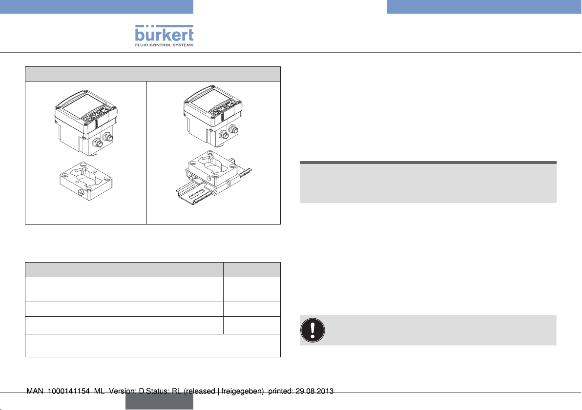
5.4. The various mounting and
installation models
The process controller Type 8611 is available in the following
models (see also chapter “7.1. Assembly models”):
• For installation in a pipeline system
• For attachment to a proportional valve
• For wall assembly or for assembly on a rail
• For installation in a control cabinet
Fig. 2: Interfaces of the process controller Type 8611
english
9
Page 10

Type 8611
Technical Data
Particularities of the control cabinet model:
Unlike the remaining assembly models, the cabinet model of
type 8611 has not one but two binary outputs.
5.5. Software
In the following description of the menu options and their operating
structures, the entire software of the eCONTROL Type 8611 is
explained. This complete software scope is only available for the control
cabinet model of the eCONTROL Type 8611.
The menu structure may vary depending on the device model (wall,
valve, rail or fitting assembly). In accordance with the device model, only
menu options that are logically purposeful for the application area can
be selected. This pre-selection is made upon delivery of the controller
in accordance with the chosen order part number.
6. TECHNICAL DATA
6.1. Operating Conditions
Permitted ambient temperature:
(operation and storage) 0 ... +70 °C
Protection class: IP65 to EN 60529
6.2. Conformity with the following
standards
CE mark conforms to
EMC Directive: EN61326
6.3. General Technical Data
Materials
Housing, cover: PC, + 20 % glass fiber
Front plate foil: Polyester
Screws: Stainless steel
Multipin: CuZn, nickel-plated
Wall assembly bracket: PVC
10
english
Page 11

Type 8611
Technical Data
Assembly
Installation position: Any position
Assembly models: Attachment to a pipeline with
Bürkert flow-rate fitting Type
S030
wall assembly, rail assembly,
valve assembly, control cabinet
assembly
Display: 2-line,
(see “Fig. 10: Display
elements”)
Operating voltage: Multipin: 3-pin or / and 4-pin
M8, 8-pin M12
2
Power cable: 0.5 mm
max. 100 m long, screened
max. cross section,
6.4. Rating plate description
The rating plate contains important technical data for the specific
device. The structure of the rating plate is described below by way
of example.
6.4.1. Rating plate of the controllers for
wall, rail, valve or fitting assembly
Example:
Controller
type
8611 Wall 24VDC
IN:Norm OUT:Norm
SET: Norm ACT: PWM
S/N xxxxxx
00177462
Serial number
Sensor input signal
(Norm, Pt 100 or Freq (NPN))
Assembly model
- Wall (wall assembly)
- Rail (rail assembly)
- Valve (assembly directly on valve)
- Fitting (assembly directly on flow-rate fitting)
Power supply voltage
Analog output
W16LU
(Norm or None)
Controller output signal
(PWM or Norm)
Set-point value input signal
Manufacturer's code
Order part number
Fig. 3: Example: Rating plate of the controllers for wall, rail, valve
or fitting assembly
english
11
Page 12

Type 8611
Technical Data
6.4.2. Rating plate of the control cabinet
model
Example:
Controller type
Assembly model
- Panel (control cabinet
8611 Panel 24VDC
Prozessregler
Power supply voltage
Controller design
S/N xxxxxx
00210206
Serial number
Fig. 4: Example: Rating plate of the control cabinet model
W16LU
Manufacturer's code
Order part number
6.5. Electrical Data
Operating voltage: 24 V DC ±10 %,
filtered and controlled
Power consumption without load: approx. 2 W
with load: maximum 48 W
100 % ED: 36 W
Controller sampling rate: 300 Hz
6.5.1. Inputs
Set-point value
Standard 4 - 20 mA Input impedance: 70 Ω
Resolution: 5.5 µA
Standard 0 - 10 V Input impedance: 11.5 kΩ
Resolution: 2,5 mV
Sensors
Standard 4 - 20 mA Input impedance: 70 Ω
Resolution: 5.5 µA
Frequecy
Input 1 External sensor
Frequency range: min. 0.25 Hz / max. 1 kHz
Input resistance: > 1 kΩ
Signal types: Sine, rectangle, triangle
(> 3000 mVss, max. 30 Vss)
Input 2 Internal Hall sensor
Frequency range: min. 0.25 Hz / max. 1 kHz
(only in conjunction with Bürkert
flow-rate fitting Type S030)
Pt 100
(2-wire) Measuring range: 0 °C ... 200 °C
Measured current: 1 mA
Measuring error: < 0.5 °C
12
english
Page 13

Type 8611
Assembly
Binary input Input impedance: 10 kΩ
Response threshold: 3 ... 30 V
Max. frequency: 1 kHz
6.5.2. Outputs
Continuous signal Standard signal 4 - 20 mA
Max. loop resistance: 680 Ω
Precision: 0,5 %
Standard signal 0 - 10 V
Maximum current: 20 mA
Precision: 0,5 %
Discontinuous signal 2 transistor outputs for PWM or
PTM control
Control frequency: 1.2 kHz ... 20 Hz
Max. resolution: 16 bit (depending on
frequency)
Max. current per
unit area: 1.5 A
Switching voltage: 24 V DC
Binary output Transistor output (PNP) configurable
Max. current per
unit area: 1.5 A
Switching voltage: 24 V DC
Sensor supply: 24 V DC
Total load for all outputs: 1,5 A
7. ASSEMBLY
7.1. Assembly models
Attachment to a Bürkert
flow-rate fitting
Bürkert
flow-rate
fitting Type
SO30
Installation in a control cabinet
Attachment to a proportional
valve
The description of the installation in a control cabinet and the
device dimensions can be found
in the following chapter “7.3.
Assembly of the control cabinet
model”
english
13
Page 14
Type 8611
Assembly
Wall assembly or rail assembly
Adapter for wall assembly Adapter for rail assembly
Tab. 1: Assembly models
7.1.1. Assembly accessories
Model Accessories Order no.
Installation in pipeline Flow-rate fitting, Type
S030
Rail assembly Adapter for rail assembly 655980
Wall assembly
The adapters for the wall and rail assembly are included in the
scope of supply of the assembly model.
Tab. 2: Assembly accessories
Adapter for wall assembly
See data
sheet S030
427098
7.2. Attachment to a proportional
valve
Attach the process controller Type 8611 to a proportional valve as
described below.
→ Loosen the 4 screws at the front of the process controller.
NOTE!
Be careful when opening the process controller so as not to
damage the internal cabling.
• Remove the cover carefully from the housing without jerks.
→ Remove the cover carefully from the housing.
→ Place the supplied flat seal over the contact tabs.
→ Attach the housing of the process controller on the contact tabs
and fasten with the valve screw.
→ Check the correct position of the profile gasket at the housing of
the process controller.
→ Place cover on the housing of the process controller and fasten
with 4 screws.
If necessary, the cover can also be mounted in a position
rotated by 90 ° to the left or the right.
14
english
Page 15

Type 8611
Assembly
Proportional valve
7.3. Assembly of the control cabinet
model
Housing of the process controller
Cover of
the process
controller
Contact tabs
Profile gasket
Valve screw
4 screws for fastening the cover
Fig. 5: Attachment of the process controller to a proportional
valve
Flat seal
54.2
66
44.5
Control panel recess for
the installation
Fig. 6: Device dimensions and control panel recess
76
R 3
45
29
english
15
Page 16

Type 8611
Assembly
7.3.1. Installation in a control cabinet
• Prepare control panel recess with the dimensions 45mm x 45mm
(corner radius 3mm).
• Place the supplied seal on the housing.
• Insert the controller from the front into the control panel recess.
• From the rear, snap the 4 supplied fastening elements into place
and fasten using a screwdriver.
4 Fastening elements
Seal
Fig. 7: Installation elements Fig. 8: Installed controller
Recommended line cross sections for the control cabinet
model:
Cross
section
min.
Cross section for
flexible lines
Cross section for
flexible lines with
cable end sleeve
without plastic
sleeve
Cross section for
flexible lines with
cable end sleeve
with plastic sleeve
Tab. 3: Recommended line cross sections
0.2 mm² 1.5 mm² 10 mm
0.25 mm² 1.5 mm² 10 mm
0.25 mm² 0.75 mm² 10 mm
Cross
section
max.
Minimum
length
(stripping)
16
english
Page 17

Type 8611
Electrical Installation
8. ELECTRICAL INSTALLATION
8.1. Electrical installation for fitting
assembly, wall assembly, valve
assembly or rail assembly
models
8.1.1. Connection versions
Connector
Circular
plug-in
connector
M12,
8-pole
Circular
plug-in
connector
M8, 3-pole
Connector
view
5
6
7
1
8
Configuration
Power supply voltage,
set-point input 4 - 20 mA / 0 - 10 V,
process actual value or position setpoint output 4 - 20 mA / 0 - 10 V,
4
binary input,
3
binary output
2
Note!
A straight plug (female) is recommended for the connecting cable, as
the alignment of the plug can vary.
Connection sensor
4
(4 - 20 mA / 0 - 10 V, Pt 100 or
31
frequency)
and sensor supply 24 V DC
Connector
Circular
plug-in
connector
M8, 4-pole
Connector
view
2
1
Configuration
Connection actuating element
4
• Proportional valve (1 x PWM)
• Process valve (1 x PTM)
• Manipulated variable 4 - 20 mA /
3
0 - 10 V and sensor supply 24 V DC
(only ID 182383)
DIN-EN
175301
Tab. 4: Connection versions for assembly on flow-rate fitting, wall
assembly, rail assembly or valve assembly
Connection for direct assembly on
proportional valve (1 x PWM) or
open/closed valve (1 x PTM)
12
english
17
Page 18

5
4
Type 8611
Electrical Installation
8.1.2. Pin assignment
Circular plug-in connector M12, 8-pole
A straight connector (female) is recommended for the connecting cable as the orientation of the connector may vary.
Connector
diagram
6
7
1
8
Tab. 5: Configuration of circular plug-in connector M12, 8-pole
Pin Color Configuration
4
3
2
1
2 (DIN2)
3
white 24 V DC power supply
brown Binary input (B_IN)
green GND – Power supply,
binary input, binary output
4 (AOUT)
yellow 4 - 20 mA or 0 - 10 V analog
output
(process value or manipulated
variable for valve)
5 (AIN2)
grey 4 - 20 mA or 0 - 10 V analog
input (set-point value / ratio)
6
7
pink GND – Analog output
blue GND – Analog input
(set-point value / ratio)
8 (BO1)
red (+) Binary output (B_O1)
Wire colors when using standard cables (e.g. from
Lumberg, Escha)
8.1.3. Sensor connection
Circular plug-in connector M8, 3-pole
31
Input
signal
4 - 20 mA
2-wire
supply of
Type 8611
(AIN1)
4 - 20 mA
/ 0 - 10 V
3-wire
supply of
Type 8611
(AIN1)
Pin Color
1 brown
3 blue
4 black
1 brown
3 blue GND
4 black
Configuration
+ 24 V
sensor
supply
not
connected
Signal input
(source)
+ 24 V
sensor
supply
Signal input
(source)
External circuit
4
3
4
1
1
I
24 V DC
4 - 20 mA
24 V DC
GND
4 - 20 mA /
0 - 10 V
Transmitter
Transmitter
18
english
Page 19

Type 8611
Electrical Installation
Input
signal
4 - 20 mA
/ 0- 10 V
4-wire
external
supply
(AIN1)
Frequency
3-wire
supply of
Type 8611
(DIN1)
Frequency
4-wire
external
supply
(DIN1)
Pin Color
1 brown
3 blue GND
4 black
1 brown
3 blue GND
4 black
1 brown
3 blue GND
4 black
Configuration
not
connected
Signal input
(source)
+ 24 V
sensor
supply
Frequency
input (NPN)
not
connected
Frequency
input (NPN)
External circuit
Trans-
GND
3
4
4 - 20 mA /
1
3
4
GND
3
4
Clock (DIN1)
mitter
0 - 10 V
24 V DC
GND
Clock (DIN1)
Trans-
mitter
Transmitter
GND
Supply
GND
Supply
Input
signal
Pt 100
(2-wire)
(AIN3)
Tab. 6: Sensor connection: Configuration of circular plug-in
Pin Color
1 brown
3 blue
4 black
connector M8, 3-pole
Configuration
not
connected
GND Pt
100
(+) Pt 100
(power
supply)
External circuit
Pt 100
3
4
english
19
Page 20

2
4
Type 8611
Electrical Installation
8.1.4. Valves connection
Circular plug-in connector M8, 4-pole
1
Output
signal:
PWM
(MODE =
SCV)
3-point
(MODE =
PCV)
3
Pin Color Configuration External circuit
1 brown not connected
2 white not connected
3 blue
4
(BO4)
1
(BO3)
black
brown
2 white
3 blue
4
(BO4)
black
(–) PWM
(valve2)
(+) PWM
(valve2)
(+) Aeration
(valve 1)
(–) Aeration
(valve 1)
(–) Deaeration
(valve 2)
(+) Deaeration
(valve 2)
Output
signal:
1)
4 - 20 mA
or
0 - 10 V
(MODE =
4 – 20 /
Proportional
0 – 10)
valve
3
4
1
NC valve
2
3-point
(MODE =
3P – T)
NO valve
3
Pin Color Configuration External circuit
1
(BO3)
brown
2 white
3 blue GND supply
+ 24 V DC
supply
GND
(4 - 20 mA or
0 - 10 V)
1
Supply of
8611
2
3
+ 4 - 20 mA
4
(AOUT)
black
or
0 - 10 V
manipulated
4
variable
1
(BO3)
2
3
4
(BO4)
brown
(+) Valve 1
white (–) Valve 1
blue (–) Valve 2
black (+) Valve 2
NC / NO valve
1
2
NC / NO valve
3
4
M
4
20
english
Page 21

5
Type 8611
Electrical Installation
Output
signal:
Pin Color Configuration External circuit
+ 24 V DC
1)
4 - 20 mA
or
0 - 10 V
(MODE =
4 – 20 /
0 – 10)
External
supply
1 brown
2 white
3 blue GND supply
4
(AOUT)
black
supply (max.
1A)
GND (4 - 20
mA or 0 - 10
V)
+ 4 - 20 mA
or
0 - 10 V
manipulated
External
supply
2
4
M
+ 24 V
DC
GND
variable
NC / NO valve
1
2
2-point
1
(BO3)
brown (+) Valve 1
2 white (–) Valve 1
(MODE =
2P – T)
3 blue not connected
4 black not connected
1) Only available for identification number 182383
Tab. 7: Configuration of circular plug-in connector M8, 4-pole
Circular plug-in connector M12, 8-pole
8
4
3
2
Pin Color
Configuration
External circuit
6
7
1
Output
signal:
4 - 20 mA
2)
4 - 20 mA
or
0 - 10 V
(MODE =
4 – 20 /
0 – 10)
4
(AOUT)
yellow
6 pink
or
0 - 10 V
manipulated
variable
GND –
Analog
+ 24 V
4
DC
M
6
GND
(24 V)
output
2) Available for all models except for identification number
182383
Tab. 8: Configuration of circular plug-in connector M12, 8-pole
english
21
Page 22

Type 8611
Electrical Installation
8.2. Electrical installation of the
control cabinet model
WARNING!
Risk of injury from incorrect installation!
Incorrect installation can damage or destroy the Type 8611
eCONTROL.
• The electrical installation may be performed by authorized electricians only!
Terminal block 1
1 2 3 4 5 6 7 8
Terminal block 2
91011 12 13 14 15 16 17 18
Terminal block 3
2019 21 22 23
24 25
26 27
Jumper 1
Jumper 2
8.2.1. Terminal assignment
Terminal block 1
Terminal
1
2
3
(BO2)
4
(BO1)
Configuration
GND –
Electrical
power supply
24 V DC
power supply
Binary output
2 (B_O2)
Binary output
1 (B_O1)
External circuit
1
2
(1, 6, 8, 11, or 23
(1, 6, 8, 11, or 23
GND
24 V DC
24 V DC ±10 %
max. residual ripple 10 %
3
24 V / 0 V
(max. 1 A)
NC / NO
GND)
4
24 V / 0 V
(max. 1 A)
NC / NO
GND)
Fig. 9: Control cabinet model; connection PCB with spring ter-
minals and jumpers
22
english
Page 23

Type 8611
Electrical Installation
Terminal
5
(BO3)
6
7
(BO4)
8
Tab. 9: Configuration of terminal block 1
Configuration
(+) Aeration
valve (PCV)
or valve 1
(2P – T or
3P – T)
(–) Aeration
valve (PCV)
or valve 1
(2P – T or
3P – T)
(+)
Proportional
valve (SCV),
bleed valve
(PCV) or
valve 2
(3P – T)
(–)
Proportional
valve (SCV),
bleed valve
(PCV) or
valve 2
(3P – T)
External circuit
MODE = 2P – T
or 3P – T
5
6
NC / NO
valve max. 1 A
MODE = 3P – T
7
8
NC / NO
valve max. 1 A
MODE = PCV
7
8
NO
valvel max. 1 A
MODE = PCV
5
6
NC
valve max. 1 A
MODE = SCV
7
8
NC
valve max. 1,5 A
Terminal block 2
Terminal Configuration External circuit
9
10
(AOUT)
11
12
13 not used not used
14
(AIN2)
15
16 RS485_COM 16
17 RS485_A (+) 17
18 RS485_B (–) 18
Tab. 10: Configuration of terminal block 2
GND –
Analog output
(+) Analog output
(process value
or manipulated
variable for valve
GND – Sensor,
actuating element
24 V DC sensor
supply or actuating
element
(+) External default
of set-point value
/ ratio
4 - 20 mA / 0 - 10 V
(+) 5 V DC sensor
supply (max. 20 mA)
9
10
11
12
14
(21
15
(1, 11 or 23
GND
4 - 20 mA /
0 - 10 V
GND
24 V DC
4 - 20 mA /
0 - 10 V
(source)
A-GND)
5 V DC
GND)
RS485_COM
RS485_A
RS485_B
english
23
Page 24

Type 8611
Electrical Installation
Terminal block 3
Terminal Configuration External circuit
19
20
(AIN3)
21
22
(AIN1)
GND – Pt 100,
RTD
(+) Pt 100,
RTD (power
supply)
GND – Analog
input
(+) Process
value input
4 - 20 mA /
0 - 10 V
21
22
21
19
20
GND – Sensor,
23
actuating
23
element
24 V DC
24
sensor supply
or actuating
24
23
element
Pt 100
(0 ... 200 °C)
A-GND
4 - 20 mA / 0 - 10 V
(source)
A-GND
GND
24 V DC - Out (max. 1 A)
GND
Terminal Configuration External circuit
25
Supply
of Type
8611
(DIN3)
25
External
supply
(DIN3)
Frequency
input 2
(NPN or PNP)
Q
for ratio
2
control (MODE
= RATI)
Frequency
input 2
(NPN or PNP)
for ratio
Q
2
control
(MODE =
Jumper 2
12 or
NPN
11 or
PNP
Jumper 2
NPN
11 or
PNP
RATI)
26
(+) Binary input
26
(DIN2)
1, 11 or 23
24
23
25
23
25
Supply of 8611
24 V DC
GND
Trans-
mitter
Clock
External supply
Supply
GND
Trans-
mitter
Clock
0 ... 2,7 V
(log. 0)
3 ... 30 V
(log. 1)
GND
GND
max.
1 kHz
24
english
Page 25

Type 8611
Operation and Function
Terminal Configuration External circuit
27
Supply
of Type
8611
(DIN1)
27
External
supply
(DIN1)
Tab. 11: Configuration of terminal block 3
Frequency
input 1
(NPN or PNP)
Actual value
flow-rate /
Q
for ratio
1
control
(MODE =
RATI)
Frequency
input 1
(NPN or PNP)
Actual value
flow-rate /
for ratio
Q
1
control (MODE
= RATI)
Jumper 1
NPN
PNP
Jumper 1
NPN
PNP
12 or
24
11 or
23
27
11 or
23
27
Supply of 8611
24 V DC
GND
GND
Trans-
mitter
Clock
External supply
Suply
Trans-
mitter
Clock
GND
9. OPERATION AND FUNCTION
9.1. Control and display elements
The control and display element of the eCONTROL Type 8611 is
equipped with 3 buttons and an LCD-Matrix display.
9.1.1. Display elements
4-character display
7-character matrix for
numerical values
4-character display
14-character matrix for
measuring units and
parameter designations
10-segment bar graph
for display of the manipulated variable in % (One
Is displayed for
external set-point
value default
Is displayed when the
control is activated
Indicates the operating
state Manual
Segment indicates 10 %
of manipulated variable)
Red LED is lit in case of
an alarm
Fig. 10: Display elements
english
25
Page 26

Type 8611
Operation and Function
9.1.2. Control elements
Arrow keys
• Change the display at the process operating level in AUTOMATIC operating state
left right
ENTER button
The detailed description of the function can be found in chapter
“9.3. Funktion of the keys”.
• Change the menu options in MANUAL
operating mode and at the
configuration level
• Entering of numerical values
• Switches between the operating states
AUTOMATIC and MANUAL
• Switches between operating and configuration level
• Selection of menu option
• Take over settings
9.2. Operating levels and operating
states
2 operating levels and 2 operating states AUTOMATIC and MANUAL
are available for the operation and setting of the eCONTROL Type
8611.
Level 1: Process operating level
At level 1, the user can switch between 2 operating
states AUTOMATIC and MANUAL.
Operating state: AUTOMATIC: The normal control
mode is executed and monitored.
MANUAL: Quick access to important
functions and test functions.
The operating state
MANUAL is indicated on the
display by a hand symbol.
Level 2: Configuration level
At level 2, the user can change the basic settings of the
controller.
After switching on the operating voltage, the controller is at the
process operating level and in the AUTOMATIC operating state.
When the operating voltage is applied, the software version will light
up on the display for approx. 2 seconds.
If the ENTER key is pressed during these 2 seconds, the subversion is displayed. After this, the controller is once again at the
process operating level.
26
english
Page 27

Type 8611
Operation and Function
9.2.1. Switching between the operating
levels and operating states
The ENTER key is pressed to change the operating level and operating state (see Fig. 11).
Any changes made within the configuration level are only
stored after returning to the process operating level.
Changes in the Manual operating state can be made while
the controller is running.
Process operating level
Operating state
AUTOMATIK
eCONTROL
Press button
8611
> 5 s (long)
025.5
L/M
ENTER
O
u
0.....9
t
Fig. 11: Changing the operating level and operating state
< 1 s (short)
Operating
SET
PARA
VALV
TEST
BACK
state
HAND
Configuration
level
8611
eCONTROL
MODE
ENTER
O
u
0.....9
t
MODE
UNIT.
END
.
.
.
9.3. Funktion of the keys
The device is operated using two arrow keys and one ENTER key.
The function of these in respect of the operating level and the operating state is shown in the table below.
Operating
level
Level 1:
Process
operating
level
Operating
state
AUTOMATIC
MANUAL
Switch display
between actual
value, set-point value
and manipulated
variable
Switches
to the
last
menu
option
Switches
to the
next
menu
option
Entering of values
Change
Increase
value
by one
position
to the left
• Press key briefly
(< 1 s):
Switches to
operating state
MANUAL
• Press and hold
key (> 5 s):
Switches to
configuration
level
• Selection of
menu option
• Take over
settings
• Switches to
operating state
AUTOMATIC
(for display
BACK)
english
27
Page 28

Type 8611
Functions, Process Operating Level
Operating
level
Level 2:
Configuration level
Tab. 12: Function of the keys
Operating
state
Switches
to the
last
menu
option
Entering of values
Increase
value
Switches
to the
next
menu
option
Change
by one
position
to the left
• Selection of
menu option
• Take over
settings
• Switches to
process operating level and
to operating
state AUTOMATIC (for
display END)
10. FUNCTIONS, PROCESS
OPERATING LEVEL
10.1. Operating state AUTOMATIC
After switching on the operating voltage, the controller is at the process
operating level and in the AUTOMATIC operating state. The normal
control mode is executed and monitored.
10.1.1. Displays in the AUTOMATIC
operating state
Press the arrow keys to switch between 4 different displays for monitoring the control operation. Which of these displays should be shown
as start display after applying the operating voltage can be defined in the
DSPL menu (see Operating structure of the configuration level Fig. 26).
28
english
Page 29

Type 8611
Functions, Process Operating Level
8611
025.5
L/M
0.....9
eCONTR OL
O
u
t
025.5
L/M
ENTER
Display process actual value
The display of the unit depends on the selection made in the UNIT menu
(see Operating structure of the configuration level Fig. 16).
For MODE = T – F or T + F the display switches between temperature and flow-rate.
For MODE = RATI the display switches between flow-rate Q1 and Q2
030.0
SET
030.0
RFAC
Display set-point value
The display depends on the selection made in the MODE menu (see Operating structure of the
configuration level Fig. 15).
SET = Display for process control
RFAC = Display for ratio control
For MODE = T – F or T + F the display switches between flow-rate set-point (SP_Q) and
temperture set-point (SP_T).
For MODE = RATI the display switches between ratio factor (RFAC) and
flow-rate set-point (SPQ1).
025.5
030.0
065.0
PRZV
065.0
065.0
Display process actual value
Display set-point value
Display manipulated variable for valve
Display depends on the actuating element selected in the MODE menu (see Operating structure
of the configuration level Fig. 15).
mA
PRZV = Display pulse duty factor for solenoid valve
V
mA = Display manipulated variable in mA
V = Display manipulatec variable in V
Fig. 12: Displays in the AUTOMATIC operating state
english
29
Page 30

Type 8611
Functions, Process Operating Level
10.2. Operating state MANUAL
Briefly press (< 1 s) the ENTER key to go to the MANUAL operating
state.
The operating state is indicated on the display by a hand symbol.
10.3. Specific menu options of
process and ratio control
The display of some menu options differs for the process and the
ratio control. This is described in detail in the respective menu
descriptions.
The control type is specified by the control variable selected in the
MODE menu:
• Process control: is active if all control variables have
been selected in the MODE menu
except forRATI.
• Ratio control is active if the RATI control variable has
been selected in the MODE menu
10.4. Menu options in the MANUAL
operating state
SET
RFAC
BACK
TEST
PARA
VALV
Tab. 13: Menu options of the process operating level
Set-point value default for process control
• Menu option is displayed for process control.
• Is not available if external set-point value default is
selected.
Ratio factor default for ratio control
• Menu option is only displayed for ratio control
(MODE = RATI).
• Is not available if external set-point value default is
selected.
When BACK is displayed on the display, press the
ENTER key briefly to switch to AUTOMATIC operating state.
When an arrow key is pressed, the next or respectively the previous menu option is displayed.
Display of the analog inputs and outputs and
the digital inputs.
Adjusting the controller parameters (Code must
be entered if code protection is activated).
Manual opening and closing of the connected
valves.
30
english
Page 31

Type 8611
Functions, Process Operating Level
10.5. Operating structure of the process operating level in MANUAL operating
state
SET ***
RFAC ****)
BACK
TEST
PARA
< 1 s
Changes in the MANUAL operating state can be made while the controller is running.
)
Enter set-point value
Enter ratio factor
Back to AUTOMATIC operating state
AIN1
AIN2
AIN3
DIN1
DIN2
DIN3
AOUT
4-20 mA / 0-10 V process value
4-20 mA / 0-10 V set-point value
Pt 100 input
Frequency input 1
Binary input (0 V / 24 V)
Frequency input 2
4-20 mA / 0-10 V Output
BACK
Back to AUTOMATIC operating state
Fig. 13: Operating structure of the process operating level in MANUAL operating state – 1 of 2
***) The SET menu option is only
displayed for process control.
Consequently for all control
variables set in the MODE menu
except for RATI.
)
The RFAC menu option is only
****
displayed for ratio control.
Consequently only if the RATI
control variable is set in the
MODE menu.
english
31
Page 32

Type 8611
Functions, Process Operating Level
TEST
CODE **
PARA
**) Code query only when code protection is activated
)
KP1
)
KP2 *
)
TREG *
)
TN *
DEAD
)
KP T *
)
TN T *
)
DE T *
BACK
VALV *
)
150 L/H
Open
Close
055 PRZ *
)
SET (start of the menu sequence)
Back to AUTOMATIC operating state
Proportional coefficient K
Proportional coefficient K
P1
P2
Cycle time for controller [s]
Reset time [s]
Dead zone (absolutely to the process value)
Proportional coefficient K
[∆Q / ∆°K] (cascaded temperature control)
P1
Reset time in [s] for cascaded temperature control
Dead zone [°C] (cascaded temperature control)
*) The display depends on the control variable
set in the MODE menu (see Fig. 15)
Fig. 14: Operating structure of the process operating level in MANUAL operating state – 2 of 2
32
english
Page 33

Type 8611
Configuration Level
11. CONFIGURATION LEVEL
11.1. Operating structure of the configuration level
Configuration level
CODE
UNIT,
Enter access code if the code protection has been activated in the CODE menu.
MODE
CODE
„0001“
Selection of
control variable
RATI
F
P
Selection of sensor input
for Flow-rate uncontrolled
FREQ
NORM
Selection of
actuating element
SCV
PCV
T
T – F
T + F
L
X
2P – T
3P – T
4 – 20
0 – 10
Select control frequency (PWM)
Select control times
Select control times
Select control times
Selection of sensor
input
for process variable
controlled
FREQ *
PT *
NORM *
Fig. 15: Operating structure of the configuration level - 1 of 12
english
33
Page 34

MODE
UNIT *
Selection of the measuring unit for the display
Q1 **
Q2 **
)
)
*) The display depends on the control variable set in the MODE menu.
)
**
L/H
L / M
G / H
G / M
MODE = F
ML / M
MODE = RATI
M3 / H
= T
°C
°F
NU
MODE = T+F, T-F
MODE
BAR
MBAR
= P
MODE
PSI
Type 8611
Configuration Level
Q1 and Q2 are only displayed if ratio control = RATI has been set in the MODE
menu. See Fig. 15
Selecting the decimal places
1
0.1
0.01
NU = Display without measuring unit
UNIT, MODE = L, MODE = X
Fig. 16: Operating structure of the configuration level - 2 of 12
34
english
Page 35

MODE
UNIT *
Type 8611
Configuration Level
Selection of the measuring unit for the display
*) The display depends on the control variable set in the MODE menu.
MM
CM
M
MODE = L
Ft
In
NU
PH
µS/c
mS/c
MODE = T
S/c
Ωxc
ppm
See Fig. 15
Selecting the
decimal places
1
0.1
0.01
NU = Display without measuring unit
SETP / RFAC
Fig. 17: Operating structure of the configuration level - 3 of 12
english
35
Page 36

UNIT
Selection of set-point value default and scaling of external default
SETP **
RFAC ***
)
)
Selection and scaling of sensor input
S_IN ****
)
Selection and scaling of analog output
AOUT 4 – 20
EXT
INT
4 – 20
0 – 10
0 – 10
4 – 20
0 – 10
Enter scaling
FLOW *
TEMP *
PRES *
)
LEVL*
)
VAL *
)
POS *
)
Q1 *
)
Q2*
RFAC *
Type 8611
Configuration Level
**) The SETP menu option is only displayed for
Enter scaling
process control. Consequently for all control variables set in the MODE menu except for RATI.
)
The RFAC menu option is only displayed for ratio
***
control. Consequently only if the RATI control variable
is set in the MODE menu.
)
The S_IN menu option is only displayed if standard
****
signal (NORM) was selected as sensor input.
*) The display depends on the control variable set in
the MODE menu.
)
Output of flow-rate as standard signal (only for control variable MODE = F, T + F, T - F)
)
Output of temperature as standard signal (only for control variable MODE = T, T + F, T - F)
)
Output of pressure as standard signal (only for control variable MODE = P)
Output of filling level (only for control variable MODE = L)
Output of process value (only for control variable MODE = X or T and UNIT = NU)
Output of actuating element position (only for actuating element type MODE = SCV)
Output of flow-rate Q1 for ratio control (control variable MODE = RATI)
Output of flow-rate Q2 for ratio control (control variable MODE = RATI)
)
Output of ratio factor RFAC for ratio control (control variable MODE = RATI)
Enter scaling
CALI
Fig. 18: Operating structure of the configuration level - 4 of 12
36
english
Page 37

Type 8611
Configuration Level
KFAC *
FILT
CALI
Calibration of the analog inputs and outputs
The detailed description of the CALI function can be found in the Operating Instruction of Type 8611 eCONTROL
The operating instructions can be found on the enclosed CD and on the Internet at:
www.burkert.com
Selection of K-factor for ratio control
)
Q1 **
Q2 **
)
)
FREE
BACK
Selection of Bürkert flow-rate sensor
Documentation
)
The KFAC menu option is not indicated unless a sensor with frequency input was selected in the
*
Type
MODE menu.
**) Q1 and Q2 are only displayed if frequency input (FREQ) was selected for both flow-rate sensors in
ratio control.
0.01
0.1
Enter value
The display 0.01, 0.1, 1 is used for setting the
decimal place.
Use the display 10 for setting the multiplier 10 for the
1
K-factor.
10
Fig. 19: Operating structure of the configuration level - 5 of 12
english
37
Page 38

Type 8611
Configuration Level
KFAC *
FILT
)
BACK
*) The KFAC menu option is not
indicated unless a sensor with
Selection of Bürkert flow-rate sensor
8081
QN0.6
. . . . . .
Display value
frequency input was selected in the
MODE menu.
QN6.0
8071
50L
Display value
100L
500L
S070
DN15
Display value
DN100
8031
100L
Display value
250L
S030
8030
8012
8011
VA
PVDF
PP
PVC
MS
DN06
. .
DN15
. .
DN50
Display value
V2
OLD
1)
1)
Fitting S030 and the fitting of devices
8030, 8011 and 8012, DN15, exist in
2 versions. The „v2“ marking can be
found either on the bottom or on the
side of the fitting.
Fig. 20: Operating structure of the configuration level - 6 of 12
38
english
Page 39

Type 8611
Configuration Level
FILT
Selection of
controller parameters
PARA
B_IN
Enter filter factor ( 2 - 20)
*) The display depends on the control variable set in the MODE menu (see Fig. 15)
KP1
KP2 *
TREG *
TN *
DEAD
KP_T *
TN_T *
DE_T *
)
)
KP1, Pproportional coefficient 1
KP2, proportional coefficient 2
)
Cycle time for controller [s] (display only for MODE = PVC, 3P – T, 2P – T,)
Reset time [s] (display only for MODE = SCV, 0 – 10, 4 – 20, 2P – T, 3P – T,)
Dead zone absolute. Unit and display of decimal place analogous to UNIT.
)
Proportional coefficient for cascaded temperature control (display only for MODE = T + F)
)
Reset time in [s] for cascaded temperature control (display only for MODE = T + F)
)
Dead zone absolute for cascaded temperature control (display only for MODE = T + F).
Effective direction
INV
NO
YES
Not inverted or direct control
Inverted control
Zero point shut-off (if default < 2 % of the set-point value range). Display only for INV = NO
ZERO
STRT *
NO
YES
)
Definition of start value for manipulated variable
Zero point shut-off is deactivated
Zero point shut-off is activated
(display only for MODE = SCV, 0 – 10, 4 – 20, 1P – T, 3P – T)
BACK
Fig. 21: Operating structure of the configuration level - 7 of 12
english
39
Page 40

B_IN
B_O1
B_O2
Selection of binary input
NO
Inverting of the effective direction defined in the PARA menu.
INV
Manipulated variable remains in current position
HOLD
Setting of a safety position that is approached when binary input is active
SAFP
Valve movement is stopped (e.g. if the valve has reached the limit stop)
STOP **
)
Valve is being opened = OPEN, Valve is being closed = CLOS
OPEN **
CLOS **
)
)
HIGH
LOW
HIGH
LOW
HIGH
LOW
HIGH
LOW
HIGH
LOW
PRZV **
mA **
)
V **
OPEN **
CLOS **
OPEN
CLOS
Type 8611
Configuration Level
)
)
Enter value
**) The display depends on the actuating element set in the
MODE menu (see Fig. 15)
)
)
Fig. 22: Operating structure of the configuration level - 8 of 12
40
english
Page 41

Type 8611
Configuration Level
B _O1
B_O1 /
2_P
NO
Selecting binary output as pulse output
PULS
DM3 1
IGAL 0.1
UGAL 0.01
M3
Selecting binary output as limit switch
LIMT
REL
ABS
POS
Time lag
DLY XXX.X
Enter hysteresis relatively to the set-point value
FLOW *
PRES *
TEMP *
LEVL *
VAL *
Enter valve postion
Effective direction LED indication?Output signal.
INV NO LED NO
INV YES LED YES
Enter number of pulses [PU]
(HYHI, HYLO)
)
)
)
)
)
Enter process value limit
(absolute)
*) The display depends on the control variable set in the
MODE menu (see Fig. 15)
(PVHI, PVLO)
(POSL, POSH)
Error message
indication?
HIGH TEXT NO
LOW TEXT YES
Fig. 23: Operating structure of the configuration level - 9 of 12
english
41
Page 42

Type 8611
Configuration Level
B _O1
B _O2 **
VALV
NO
Selecting binary output as 2-state controller
2_P REL
SP
ABS
Enter hysteresis relatively to the set-point value
Enter limits for set-point value default
FLOW *
PRES *
TEMP *
LEVL *
VAL *
Time lag Effective direction Output signal.
DLY XXX.X
)
**) The operating structure is identical to B_O1
(HYHI, HYLO)
(SPLO, SPHI)
)
)
)
)
)
Enter process value limit
(absolute)
*) The display depends on the control variable set in the
MODE menu (see Fig. 15)
INV NO
INV YES
(PVHI, PVLO)
HIGH
LOW
Fig. 24: Operating structure of the configuration level - 10 of 12
42
english
Page 43

Configuration Level
Setting of the control range
VALV
MODE = SCV, 4 – 20, 0 – 10, 2P – T, 3P – T
Open **)
Close
MODE = PCV, 2P – T, 3P – T
Open **)
Close
Enter code protection
CODE
The following operator actions are blocked if code protection is activated:
• Changing the controller parameters in manual mode under the PARA menu
• Access to the configuration level
Type 8611
L / H *
)
PRZ *
L / H *
)
)
END
MIN
MAX
END
MIN
MAX
Back without store
Store as MIN value
Store as MAX value
Back without store
Enter MIN
Enter MAX
*) The display depends
on the control variable
set in the MODE
menu (see Fig. 15)
)
Press the up arrow
**
key to open the
actuating element,
and the down arrow
key to close the
actuating element.
Factory setting:
Upon delivery from the factory, the display in the CODE menu is set to 0000. This means that the code protection is not activated. Switching to the configuration level is done without query of the code.
DSPL
Fig. 25: Operating structure of the configuration level - 11 of 12
english
43
Page 44

Setting the
display
DSPL
YES
Reset to the factory settings
FACT
CODE NO
"0003"
NO
Type 8611
Configuration Level
Activation of the background lighting:
The background lighting remains switched on continuously
The background lighting switches on when the button is pressed and switches off automatically after 60
seconds
Define what value or what manipulated variable should be displayed after switching on the voltage
CMD
BOTH
PVAL
SETP
Display manipulated variable
Display set-point value and process actual value
Display process actual value
Display set-point value
YES
U_xx
B_xx
END
Display program version
Display software version
Switching to the process operating level – AUTOMATIC operating state
Fig. 26: Operating structure of the configuration level - 12 of 12
44
english
Page 45

Type 8611
Overview Setting parameters
12. OVERVIEW SETTING PARAMETERS
Continuous control Quasi-continuous control Discontinuous control
Actuating element Proportional
valve
Program MODE
Control frequency
Operating principle [-] [-] [-] [-] NC/NO NC/NO NC/NO NC/NO
(MODE)
Minimum control
time
Valve parameter
Control structure PI oder P (TN = 9999) P PI oder P (TN = 9999) P (KP1 = 9999)
Proportional gain KP1
Reset time TN [s] TN [s] TN [s] [-] TN [s] TN [s] [-] [-]
Cycle time [-] [-] [-] TREG [s] TREG [s] TREG [s] [-] [-]
Dead zone DEAD
Control direction
Zero point shut-off
Control parameter (PARA)
Startposition of
control
Tab. 14: Overview setting parameters
SCV 0-10 4-20 PCV 2P – T 3P – T 2P – T 3P – T
PWM
[-] [-] [-] TMN1/TMN2
[%/PV]
[∆ PV]
INV
(Yes/No)
ZERO
(Yes/No)
STRT
[0-100]
Linear actuating
element
[-] [-] [-] [-] [-] [-] [-]
KP1
[%/PV]
DEAD
[∆ PV]
INV
(Yes/No)
ZERO
(Yes/No)
STRT
[0-10]
DEAD
[∆ PV]
INV
(Yes/No)
ZERO
(Yes/No)
STRT
[4-20]
Process
valve
[ms]
KP1
[%/PV]
DEAD
[∆ PV]
INV
(Yes/No)
ZERO
(Yes/No)
[-] STRT
Open/closed
valve
TMN1
[ms]
KP1
[%/PV]
DEAD
[∆ PV]
INV
(Yes/No)
ZERO
(Yes/No)
[0-100]
Open/closed
rotary actuator
TMN1/TMN2
[ms]
KP1
[%/PV]
DEAD
[∆ PV]
INV
(Yes/No)
ZERO
(Yes/No)
STRT
[0-100]
Open/closed
valve
TMN1
[ms]
KP1
(=9999)
DEAD
[∆ PV]
INV
(Yes/No)
ZERO
(Yes/No)
[-] [-]
Open/closed
valve
TMN1/TMN2
[ms]
KP1 / KP2
(=9999)
DEAD
[∆ PV]
INV
(Yes/No)
ZERO
(Yes/No)
english
45
Page 46

Additional control parameters for setting a cascaded control loop (MODE = T + F)
Continuous control Quasi-continuous control Discontinuous control
Control structure PI oder
P (TN = 9999)
P PI oder
Type 8611
Overview Setting parameters
P (TN = 9999)
P
(KP1 = 9999)
Proportional gain KP_T
[%/°K]
Reset time TN_T
(PARA)
Dead zone DEAD
Reglerparameter
Tab. 15: Overview: additional control parameters for setting a cascaded control loop
46
[s]
[∆ °K]
english
KP_T
[%/°K]
TN_T
[s]
DEAD
[∆ °K]
KP_T
[%/°K]
TN_T
[s]
DEAD
[∆ °K]
KP_T
[%/°K]
TN_T
[s]
DEAD
[∆ °K]
KP_T
[%/°K]
TN_T
[s]
DEAD
[∆ °K]
KP_T
[%/°K]
TN_T
[s]
DEAD
[∆ °K]
KP_T
[%/°K]
TN_T
[s]
DEAD
[∆ °K]
KP_T
[%/°K]
TN_T
[s]
DEAD
[∆ °K]
Page 47

Type 8611
Packaging and Transport
13. PACKAGING AND TRANSPORT
NOTE!
Transport damages!
Inadequately protected equipment may be damaged during
transport.
• During transportation protect the device against moisture and
dirt in shock-resistant packaging.
• Do not allow the temperature to exceed or drop below the permitted storage temperature.
14. STORAGE
NOTE!
Incorrect storage may damage the device.
• Store the device in a dry and dust-free location!
• Storage temperature: 0 – +70 °C.
15. DISPOSAL
→
Dispose of the device and packaging in an environmentally friendly
manner.
NOTE!
Damage to the environment caused by device components
contaminated with media.
• Observe applicable disposal regulations and environmental
regulations.
Observe national waste disposal regulations.
english
47
Page 48

Type 8611
Packaging and Transport
48
english
Page 49

Inhalt:
Typ 8611
eCONTROL 8611: Prozessregler und Verhältnisregler
1. DER QUICKSTART ....................................................................................... 51
1.1. Darstellungsmittel ..............................................................................51
2. BESTIMMUNGSGEMÄSSE VERWENDUNG ...................................52
2.1. Beschränkungen .................................................................................52
2.2. Vorhersehbarer Fehlgebrauch .....................................................52
3. GRUNDLEGENDESICHERHEITSHINWEISE .................................. 53
4. ALLGEMEINE HINWEISE .......................................................................... 54
4.1. Kontaktadressen .................................................................................54
5. SYSTEMBESCHREIBUNG ....................................................................... 54
5.1. Allgemeine Beschreibung .............................................................. 54
5.2. Schnittstellen des Prozessreglers Typ 8611 ...................... 54
5.3. Funktionen .............................................................................................. 55
5.4. Die verschiedenen An- und Einbauvarianten ......................55
5.5. Software ...................................................................................................56
6. TECHNISCHE DATEN ................................................................................ 56
6.1. Betriebsbedingungen .......................................................................56
6.2. Konformität mit folgenden Normen ..........................................56
6.3. Allgemeine Technische Daten .....................................................56
6.4. Typschildbeschreibung .................................................................... 57
6.5. Elektrische Daten ................................................................................58
7. MONTAGE ........................................................................................................59
7.1. Montagevarianten ...............................................................................59
7.2. Anbau an ein Proportionalventil .................................................. 60
7.3. Montage der Schaltschrankvariante ......................................... 61
8. ELEKTRISCHE INSTALLATION ..............................................................63
8.1. Elektrische Installation für Montagevarianten
Fittingmontage, Wandmontage, Ventilmontage
oder Hutschienenmontage ............................................................63
8.2. Elektrische Installation der Schaltschrankvariante ..........68
9. BEDIENUNG UND FUNKTION .............................................................. 71
9.1. Bedien- und Anzeigeelemente ....................................................71
9.2. Bedienebenen und Betriebszustände .....................................72
9.3. Funktion der Tasten ...........................................................................73
deutsch
49
Page 50

10. FUNKTIONEN DER PROZESSBEDIENEBENE ........................... 74
10.1. Betriebszustand AUTOMATIK .................................................... 74
10.2. Betriebszustand HAND .................................................................76
10.3. Spezifische Menüpunkte der Prozess- und
Verhältnisregelung ........................................................................... 76
10.4. Menüpunkte im Betriebszustand HAND ..............................76
10.5. Bedienstruktur der Prozessbedienebene im
Betriebszustand HAND .................................................................77
11. KONFIGURATIONSEBENE ...................................................................79
11.1. Bedienstruktur der Konfigurationsebene ............................ 79
12. ÜBERSICHT EINSTELLPARAMETER ............................................... 91
13. VERPACKUNG, TRANSPORT .............................................................. 93
14. LAGERUNG ...................................................................................................93
15. ENTSORGUNG ............................................................................................93
Typ 8611
50
deutsch
Page 51

Typ 8611
Der Quickstart
1. DER QUICKSTART
Der Quickstart beschreibt den gesamten Lebenszyklus des Gerätes.
Bewahren Sie diese Anleitung so auf, dass sie für jeden Benutzer gut
zugänglich ist und jedem neuen Eigentümer des Gerätes wieder zur
Verfügung steht.
Wichtige Informationen zur Sicherheit!
Lesen Sie den Quickstart sorgfältig durch. Beachten Sie vor
allem die Kapitel Grundlegende Sicherheitshinweise und Bestim-
mungsgemäße Verwendung.
• Der Quickstart muss gelesen und verstanden werden.
Der Quickstart erläutert beispielhaft die Montage und Inbetriebnahme des Gerätes.
Die ausführliche Beschreibung des Gerätes finden Sie in der Bedienungsanleitung für den Typ 8611 eCONTROL.
Die Bedienungsanleitung finden Sie auf der beigelegten CD
oder im Internet unter:
www.buerkert.de
1.1. Darstellungsmittel
In dieser Anleitung werden folgende Darstellungsmittel verwendet.
GEFAHR!
Warnt vor einer unmittelbaren Gefahr!
• Bei Nichtbeachtung sind Tod oder schwere Verletzungen die
Folge.
WARNUNG!
Warnt vor einer möglicherweise gefährlichen Situation!
• Bei Nichtbeachtung können schwere Verletzungen oder Tod die
Folge sein.
VORSICHT!
Warnt vor einer möglichen Gefährdung!
• Nichtbeachtung kann mittelschwere oder leichte Verletzungen
zur Folge haben.
HINWEIS!
Warnt vor Sachschäden!
Wichtige Tipps und Empfehlungen.
verweist auf Informationen in dieser Anleitung oder in
anderen Dokumentationen.
→ markiert einen Arbeitsschritt, den Sie ausführen müssen.
deutsch
51
Page 52

Typ 8611
Bestimmungsgemäße Verwendung
2. BESTIMMUNGSGEMÄSSE
VERWENDUNG
Bei nicht bestimmungsgemäßem Einsatz des Prozessreglers
Typ 8611 können Gefahren für Personen, Anlagen in der
Umgebung und die Umwelt entstehen.
• Der Prozessregler ist dafür bestimmt, in Verbindung mit einem
Proportional- oder Prozessventil und einem Sensor die Prozessgröße für Druck, Temperatur oder Durchfluss zu regeln.
• Das Gerät nicht im Außenbereich einsetzen.
• Für den Einsatz die in den Vertragsdokumenten und der Bedienungsanleitung spezifizierten zulässigen Daten, Betriebs- und
Einsatzbedingungen beachten. Diese sind im Kapitel“ Technische Daten“ beschrieben.
• Das Gerät nur in Verbindung mit von Bürkert empfohlenen bzw.
zugelassenen Fremdgeräten und -komponenten einsetzen.
• Voraussetzungen für den sicheren und einwandfreien Betrieb
sind sachgemäßer Transport, sachgemäße Lagerung und Installation sowie sorgfältige Bedienung und Instandhaltung.
• Setzen Sie das Gerät nur bestimmungsgemäß ein.
2.1. Beschränkungen
Beachten Sie bei der Ausfuhr des Systems/Gerätes gegebenenfalls
bestehende Beschränkungen.
2.2. Vorhersehbarer Fehlgebrauch
• Den Typ 8611 dürfen Sie nicht in explosionsgefährdeten Bereichen
einsetzen.
• Belasten Sie das Gehäuse nicht mechanisch (z. B. durch Ablage
von Gegenständen oder als Trittstufe).
52
deutsch
Page 53

Typ 8611
Grundlegende Sicherheitshinweise
3. GRUNDLEGENDE
SICHERHEITSHINWEISE
Diese Sicherheitshinweise berücksichtigen keine
• Zufälligkeiten und Ereignisse, die bei Montage, Betrieb und Wartung
der Geräte auftreten können.
• ortsbezogenen Sicherheitsbestimmungen, für deren Einhaltung, auch
in Bezug auf das Montagepersonal, der Betreiber verantwortlich
ist.
Allgemeine Gefahrensituationen.
Zum Schutz vor Verletzungen ist zu beachten:
• Installationsarbeiten dürfen nur von autorisiertem Fachpersonal
mit geeignetem Werkzeug ausgeführt werden.
• Nach einer Unterbrechung der elektrischen oder pneumatischen
Versorgung ist ein definierter oder kontrollierter Wiederanlauf
des Prozesses zu gewährleisten.
• Das Gerät darf nur in einwandfreiem Zustand und unter Beachtung der Bedienungsanleitung betrieben werden.
• Für die Einsatzplanung und den Betrieb des Gerätes müssen
die allgemeinen Regeln der Technik eingehalten werden.
HINWEIS!
Elektrostatisch gefährdete Bauelemente / Baugruppen!
Das Gerät enthält elektronische Bauelemente, die gegen elektrostatische Entladung (ESD) empfindlich reagieren. Berührung
mit elektrostatisch aufgeladenen Personen oder Gegenständen
gefährdet diese Bauelemente. Im schlimmsten Fall werden sie
sofort zerstört oder fallen nach der Inbetriebnahme aus.
• Beachten Sie die Anforderungen nach EN 61340-5-1 und 5-2,
um die Möglichkeit eines Schadens durch schlagartige elektrostatische Entladung zu minimieren bzw. zu vermeiden!
• Achten Sie ebenso darauf, dass Sie elektronische Bauelemente
nicht bei anliegender Versorgungsspannung berühren!
Die Prozessregler Typ 8611 wurde unter Einbeziehung der
anerkannten sicherheitstechnischen Regeln entwickelt und
entspricht dem Stand der Technik. Trotzdem können Gefahren
entstehen.
Bei Nichtbeachtung dieser Bedienungsanleitung und ihrer Hinweise
sowie bei unzulässigen Eingriffen in das Gerät entfällt jegliche Haftung unsererseits, ebenso erlischt die Gewährleistung auf Geräte
und Zubehörteile!
deutsch
53
Page 54

Typ 8611
Allgemeine Hinweise
4. ALLGEMEINE HINWEISE
4.1. Kontaktadressen
Deutschland
Bürkert Fluid Control Systems
Sales Center
Christian-Bürkert-Str. 13-17
D-74653 Ingelfingen
Tel. + 49 (0) 7940 - 10 91 111
Fax + 49 (0) 7940 - 10 91 448
E-mail: info@de.buerkert.com
International
Die Kontaktadressen finden Sie auf den letzten Seiten der
gedruckten Bedienungsanleitung.
Außerdem im Internet unter:
www.burkert.com
5. SYSTEMBESCHREIBUNG
5.1. Allgemeine Beschreibung
Der Prozessregler Typ 8611 ist für die Einbindung in einen geschlossenen Regelkreis vorgesehen und kann für vielfältige Regelaufgaben
in der Fluidtechnik verwendet werden. Das nachfolgende Bild zeigt die
Integration des Reglers in einen geschlossenen Regelkreis.
Führungsgröße w
(Sollwert)
Bild 1: Blockschaltbild eines geschlossenen Regelkreises
Regler
8611
+
_
X
Stellgröße y
Rückführung Prozess-Istwert
5.2. Schnittstellen des
Prozessreglers Typ 8611
Je nach Regelstrecke und Prozess stehen verschiedene Reglerstrukturen und verschiedene Ein-/Ausgänge für die Messung des
Regelstecke
Stell-
Sensor Prozess
glied
Regelgröße
54
deutsch
Page 55

Typ 8611
Systembeschreibung
Prozess-Istwertes und für die Ansteuerung der Stellglieder zur Verfügung. Die nachfolgende Übersicht zeigt die verfügbaren Schnittstellen des Prozessreglers.
Versorgung
24 V DC
24 / 5 V DC
Spannungsversorgung für
Sensoren
Ext. Sollwertvorgabe
oder Verhältnis
4 - 20 mA /
0 - 10 V
Sensoreingänge
4 - 20 mA /
0 - 10 V,
Frequenz, Pt 100
Binäreingang
0-30 V DC
Prozess-
Versorgung
regler
eCONTROL
Typ 8611
Eingänge
Analogausgang
4 - 20 mA /
0 - 10 V
Transistorausgänge
PWM, 2P – T,
3P – T
Prozesswertausgang
Ausgänge
4 - 20 mA /
0 - 10 V
Binärausgang
0 / 24 V
(NC / NO)
RS485
Option, nur für
Schaltschrankvariante
Schnittstellen
Bedienung
5.3. Funktionen
Mit dem Prozessregler Typ 8611 eCONTROL können folgende
Regelaufgaben durchgeführt werden:
• Festwertregelung (einschleifiger Regelkreis)
• Folgeregelung (externer Sollwert)
• Verhältnisregelung
• Kaskadenregelung
An die skalierbaren Reglereingänge können wahlweise Normsignale
(Strom / Spannung) und frequenzanaloge Signale angelegt oder
Widerstandsthermometer (Pt 100) angeschlossen werden.
Als Reglerausgänge sind Ausgänge für stetige Normsignale (Strom /
Spannung) oder Transistorausgänge nutzbar. Über die Transistorausgänge können Ventile oder andere schaltende Stellglieder betätigt werden.
Außerdem sind ein Binäreingang und bis zu 2 Binärausgänge für
Zusatzfunktionen vorhanden.
5.4. Die verschiedenen An- und
Einbauvarianten
Den Prozessregler Typ 8611 gibt es in folgenden Varianten (siehe
auch Kapitel „7.1. Montagevarianten“):
• Zum Einbau in ein Rohrleitungssystem
• Zum Anbau an ein Proportionalventil
• Für die Wandmontage oder zur Montage auf eine Hutschiene
• Zum Einbau in einen Schaltschrank
Bild 2: Schnittstellen des Prozessreglers Typ 8611
deutsch
55
Page 56

Typ 8611
Technische Daten
Besonderheiten der Schaltschrankvariante:
Bei der Schaltschrankvariante des Typs 8611 stehen
abweichend zu den übrigen Montagevarianten nicht nur
einer sondern zwei Binärausgänge zur Verfügung.
5.5. Software
In der nachfolgenden Beschreibung der Menüpunkte und ihrer Bedienstrukturen wird die komplette Software des eCONTROL Typ 8611
erklärt. Dieser komplette Softwareumfang steht nur bei der Schaltschrankvariante des eCONTROL Typ 8611 zur Verfügung.
Je nach Gerätevariante (Wand-, Ventil-, Hutschienen- oder Fittingmontage) kann die Menüstruktur abweichen.
Entsprechend der Gerätevariante werden nur die für den Einsatzbereich logisch sinnvollen Menüpunkte zur Auswahl angeboten. Diese
Vorauswahl erfolgt bei Auslieferung des Reglers entsprechend der
gewählten Bestell-Identnummer.
6. TECHNISCHE DATEN
6.1. Betriebsbedingungen
Zulässige Umgebungstemperatur:
(Betrieb und Lagerung) 0 ... +70 °C
Max. zulässige Luftfeuchtigkeit: ≤ 80 %, nicht kondensierend
Schutzart: IP65 nach EN 60529
6.2. Konformität mit folgenden
Normen
CE - Zeichen konform bzgl.
EMV-Richtlinie: EN61326
6.3. Allgemeine Technische Daten
Werkstoffe
Gehäuse, Deckel: PC, + 20 % Glasfaser
Frontplattenfolie: Polyester
Schrauben: Edelstahl
Multipin: CuZn, vernickelt
Wandmontagehalter: PVC
56
deutsch
Page 57

Typ 8611
Technische Daten
Montage
Einbaulage: beliebig
Montagevarianten: Anbau an eine Rohrleitung mit
Bürkert Durchflussfitting Typ
S030
Wandmontage, Hutschienenmontage, Ventilmontage,
Schaltschrankmontage
Anzeige: 2-zeilig (siehe „Bild 10:
Anzeigeelemente“)
Betriebsspannung: Multipin: 3-Pin oder / und
4-Pin M8, 8-Pin M12
2
Stromzuleitungskabel: 0,5 mm
max. 100 m lang, abgeschirmt
max. Querschnitt,
6.4. Typschildbeschreibung
Das Typschild enthält wichtige gerätespezifische Technische Daten.
Nachfolgend ist der Aufbau des Typschild beispielhaft beschrieben.
6.4.1. Typschild der Regler für Wand-,
Hutschienen-, Ventil- oder
Fittingmontage
Beispiel:
Reglertyp
8611 Wall 24VDC
IN:Norm OUT:Norm
SET: Norm ACT: PWM
S/N xxxxxx
00177462
Seriennummer
Sensor Eingangssignal
(Norm, Pt 100 oder Freq (NPN))
Montagevariante
- Wall (Wandmontage)
- Rail (Hutschienenmontage)
- Valve (Direktmontage auf Ventil)
- Fitting (Direktmontage auf Durchflussfitting)
Versorgungsspannung
Analogausgang
W16LU
(Norm oder None)
Stellgrößenausgang (PWM
oder Norm)
Sollwert Eingangssignal
Herstellercode
Bestell Identnummer
Bild 3: Beispiel: Typschild der Regler für Wand-, Hutschienen-,
Ventil- oder Fittingmontage
deutsch
57
Page 58

Typ 8611
Technische Daten
6.4.2. Typschild der Schaltschrankvariante
Beispiel:
Reglertyp
Montagevariante
- Panel (Schaltschrank)
8611 Panel 24VDC
Prozessregler
Versorgungsspannung
Reglerausführung
S/N xxxxxx
00210206
Seriennummer
Bild 4: Beispiel: Typschild der Schaltschrankvariante
W16LU
Herstellercode
Bestell Identnummer
6.5. Elektrische Daten
Betriebsspannung: 24 V DC ±10 %, gefiltert und geregelt
Leistungsaufnahme ohne Last: ca. 2 W
mit Last: maximal 48 W
100 % ED: 36 W
Regler Abtastrate: 300 Hz
6.5.1. Eingänge
Sollwert
Norm 4 - 20 mA Eingansimpedanz: 70 Ω
Auflösung: 5,5 µA
Norm 0 - 10 V Eingansimpedanz: 11,5 kΩ
Auflösung: 2,5 mV
Sensoren
Norm 4 - 20 mA Eingansimpedanz: 70 Ω
Auflösung: 5,5 µA
Frequenz
Eingang 1 Extern-Sensor
Frequenzbereich: min. 0,25 Hz / max. 1 kHz
Eingangswiderstand: > 1 kΩ
Signalarten: Sinus, Rechteck, Dreieck
(> 3000 mVss,
max. 30 Vss)
Eingang 2 Intern Hall-Sensor
Frequenzbereich: min. 0,25 Hz / max. 1 kHz
(nur in Verbindung mit
Bürkert Durchflussfitting
Typ S030)
Pt 100
(2-Leiter) Messbereich: 0 °C ... 200 °C
Messstromstärke: 1 mA
Messfehler: < 0,5 °C
58
deutsch
Page 59

Typ 8611
Montage
Binäreeingang Eingansimpedanz: 10 kΩ
Ansprechschwelle: 3 ... 30 V
Max. Frequenz: 1 kHz
6.5.2. Ausgänge
Stetiges Signal Normsignal 4 - 20 mA
Max. Schleifenwiderstand: 680 Ω
Genauigkeit: 0,5 %
Normsignal 0 - 10 V
Maximalstrom: 20 mA
Genauigkeit: 0,5 %
Unstetiges Signal 2 Transistorausgänge für PWM oder PTM
Ansteuerung
Ansteuerfrequenz: 1,2 kHz ... 20 Hz
Max. Auflösung: 16 Bit
(frequenzabhängig)
Max. Strombelastung: 1,5 A
Schaltspannung: 24 V DC
Binärausgang Transistorausgang (PNP) konfigurierbar
Max. Strombelastung: 1,5 A
Schaltspannung: 24 V DC
Sensorversorgung: 24 V DC
Summenbelastung für alle Ausgänge: 1,5 A
7. MONTAGE
7.1. Montagevarianten
Anbau an ein Bürkert
Durchflussfitting
Bürkert
Durchflussfitting Typ
S030
Einbau in einen Schaltschrank
Anbau an ein
Proportionalventil
Die Beschreibung für den
Einbau in einen Schaltschrank
und die Geräteabmessungen
finden Sie im nachfolgenden
Kapitel „7.3. Montage der
Schaltschrankvariante“.
deutsch
59
Page 60

Typ 8611
Montage
Wandmontage oder Hutschienenmontage
Adapter für die Wandmontage Adapter für die
Hutschienenmontage
Tab. 1: Montagevarianten
7.1.1. Montagezubehör
Variante Zubehör Bestell-Nr.
Einbau in Rohrleitung Durchflussfitting, Typ S030 siehe Daten-
blatt S030
Hutschienenmontage Adapter für
Hutschienenmontage
Wandmontage Adapter für Wandmontage 427098
Die Adapter für die Wand- und Hutschienenmontage sind im
Lieferumfang für die Montagevariante enthalten.
Tab. 2: Montagezubehör
655980
7.2. Anbau an ein Proportionalventil
Bauen sie den Prozessregler Typ 8611 wie nachfolgend
beschrieben an ein Proportionalventil an.
→ Die 4 Schrauben an der Frontseite des Prozessreglers lösen.
HINWEIS!
Bei unvorsichtigem Öffnen des Prozessreglers kann die
interne Verkabelung beschädigt werden.
• Deckel vorsichtig nicht ruckartig vom Gehäuse abziehen.
→ Deckel vorsichtig vom Gehäuse abziehen.
→ Beiliegende Flachdichtung über die Kontaktfahnen schieben.
→ Das Gehäuse des Prozessregler auf die Kontaktfahnen stecken
und mit der Ventilschraube festziehen.
→ Den korrekten Sitz der Profildichtung am Gehäuse des Prozess-
reglers überprüfen.
→ Deckel auf das Gehäuse des Prozessreglers aufsetzen und mit
4 Schrauben befestigen.
Falls erforderlich kann der Deckel auch um 90 ° nach links
oder rechts verdreht montiert werden.
60
deutsch
Page 61

Typ 8611
Montage
Proportionalventil
7.3. Montage der
Schaltschrankvariante
Gehäuse des Prozessreglers
Deckel des
Prozess-
reglers
Kontaktfahnen
Profildichtung
Ventilschraube
4 Schrauben zur Deckelbefestigung
Bild 5: Anbau des Prozessreglers an ein Proportionalventil
Flachdichtung
54,2
66
44,5
Schalttafelausschnitt für
den Einbau
Bild 6: Geräteabmessungen und Schalttafelausschnitt
76
R 3
45
29
deutsch
61
Page 62

Typ 8611
Montage
7.3.1. Einbau in einen Schaltschrank
• Schalttafelausschnitt mit den Maßen 45mm x 45mm (Eckenradius
3mm) vorbereiten.
• Die mitgelieferte Dichtung auf das Gehäuse aufsetzen.
• Den Regler von vorne in den Schalttafelausschnitt einsetzten.
• Von der Rückseite die 4 mitgelieferten Befestigungselemente
einrasten und mit einem Schraubendreher festspannen.
4 Befestigungselemente
Dichtung
Bild 7: Einbauelemente Bild 8: Eingebauter
Regler
Empfohlene Leitungsquerschnitte für die Schaltschrankvariante:
Querschnitt
min.
Querschnitt flexible
Leitungen
Querschnitt flexible
Leitungen mit Aderendhülse ohne
Kunststoffhülse
Querschnitt flexible
Leitungen mit
Aderendhülse mit
Kunststoffhülse
Tab. 3: Empfohlene Leitungsquerschnitte
0,2 mm² 1,5 mm² 10 mm
0,25 mm² 1,5 mm² 10 mm
0,25 mm² 0,75 mm² 10 mm
Querschnitt
max.
Mindestlänge
(Abisolierung)
62
deutsch
Page 63

2
4
Typ 8611
Elektrische Installation
8. ELEKTRISCHE INSTALLATION
8.1. Elektrische Installation
für Montagevarianten
Fittingmontage, Wandmontage,
Ventilmontage oder
Hutschienenmontage
8.1.1. Anschlussvarianten
Steckeransicht
5
6
7
1
8
Belegung
Versorgungsspannung,
Sollwerteingang 4 - 20 mA / 0 - 10 V,
Prozess-Istwert- oder Stellgrößenausgang 4 - 20 mA / 0 - 10 V,
4
Binäreingang, Binärausgang
3
Hinweis!
2
Für das Anschlusskabel wird ein
gerader Stecker (female) empfohlen,
da die Ausrichtung des Steckers variieren kann.
Anschluss Sensor
4
(4 - 20 mA / 0 - 10 V, Pt 100 oder
31
Frequenz) und Sensorversorgung 24
V DC
Stecker
Rundsteckverbinder
M12,
8-polig
Rundsteckverbinder
M8, 3-polig
Stecker
Rundsteckverbinder
M8, 4-polig
Steckeransicht
1
Belegung
Anschluss Stellglied
• Proportionalventil (1 x PWM)
• Prozessventil (1 x PTM)
• Stellgröße 4 - 20 mA / 0 - 10 V und
3
Sensorversorgung 24 V DC (nur ID
182383))
DIN-EN
175301
Anschluss für Direktmontage auf
Proportionalventil (1 x PWM)
oder Auf/Zu-Ventil (1 x PTM)
12
Tab. 4: Anschlussvarianten für Montage auf Durchflussfitting,
Wandmontage, Hutschienenmontage oder Ventilmontage
deutsch
63
Page 64

4
Typ 8611
Elektrische Installation
8.1.2. Anschlussbelegung
Rundsteckverbinder M12, 8-polig
Für das Anschlusskabel wird ein gerader Stecker (femail)
empfohlen, die die Ausrichtung des Steckers variieren kann.
Steckerbild Pin Farbe Belegung
5
6
7
1
8
Tab. 5: Belegung Rundsteckverbinder M12, 8-polig
1 weiß 24 V DC Spannungsversorgung
4
2 (DIN2) braun Binäreingang (B_IN)
3
3 grün GND – Versorgung,
2
Binäreingang, Binärausgang
4 (AOUT) gelb 4 - 20 mA oder 0 - 10 V
Analogausgang (Prozesswert
oder Stellgröße Ventil)
5 (AIN2) grau 4 - 20 mA oder 0 - 10 V
Analogeingang (Sollwert /
Verhältnis)
6 pink GND – Analogausgang
7 blau GND – Analogeingang (Sollwert
/ Verhältnis)
8 (BO1) rot (+) Binärausgang (B_O1)
8.1.3. Sensoranschluss
Rundsteckverbinder M8, 3-polig
31
Eingangssignal
4 - 20 mA,
2-Leiter
Versorgung
von Typ
8611
(AIN1)
4 - 20 mA
/ 0 - 10 V,
3-Leiter
Versorgung
von Typ
8611
(AIN1)
Pin Farbe Belegung Äußere Beschaltung
+ 24 V
1 braun
Sensorversorgung
3 blau
nicht
verbunden
Signal-
4 schwarz
eingang
(Quelle)
+ 24 V
1 braun
Sensorversorgung
3 blau GND
Signal-
4 schwarz
eingang
(Quelle)
1
4
1
3
4
I
24 V DC
4 - 20 mA
24 V DC
GND
4 - 20 mA /
0 - 10 V
Transmitter
Transmitter
Fa. Lumberg, Escha)
64
deutsch
Adernfarben bei Verwendung von Standardkabeln (z. B. von
Page 65

Typ 8611
Elektrische Installation
Eingangssignal
4 - 20 mA
/ 0 - 10 V,
4-Leiter
Versorgung
extern
(AIN1)
Frequenz
3-Leiter
Versorgung
von Typ
8611
(DIN1)
Frequenz
4-Leiter
Versorgung
extern
(DIN1)
Pin Farbe Belegung Äußere Beschaltung
1 braun
3 blau GND
4 schwarz
1 braun
3 blau GND
4 schwarz
1 braun
3 blau GND
4 schwarz
nicht
verbunden
Signaleingang
(Quelle)
+ 24 V
Sensorversorgung
Frequenzeingang
(NPN)
nicht
verbunden
Frequenzeingang
(NPN)
GND
3
4
4 - 20 mA /
0 - 10 V
24 V DC
1
GND
3
4
Takt (DIN1)
GND
3
4
Takt (DIN1)
GND
Trans-
mitter
Versorgung
Transmitter
GND
Trans-
mitter
Versorgung
Eingangssignal
Pt 100
2-Leiter
(AIN3)
Tab. 6: Sensoranschluss: Belegung Rundsteckverbinder M8,
Pin Farbe Belegung Äußere Beschaltung
1 braun
3 blau
4 schwarz
3-polig
nicht
verbunden
GND Pt
100
(+) Pt 100
(Stromspeisung)
Pt 100
3
4
deutsch
65
Page 66

Typ 8611
Elektrische Installation
8.1.4. Anschluss Ventile
Rundsteckverbinder M8, 4-polig
2
1
Ausgangssignal
PWM
(MODE =
SCV)
3 Punkt
(MODE =
PCV)
4
3
Pin Farbe Belegung Äußere Beschaltung
1 braun
2 weiß
3 blau
4
(BO4)
1
(BO3)
schwarz
braun
2 weiß
3 blau
4
(BO4)
schwarz
nicht
verbunden
nicht
verbunden
(–) PWM
(Ventil2)
(+) PWM
(Ventil2)
(+) Belüftung
(Ventil 1)
(–) Belüftung
(Ventil 1)
(–) Entlüftung
(Ventil 2)
(–) Entlüftung
(Ventil 2)
Ausgangssignal
1)
4 - 20 mA
oder
0 - 10 V
(MODE =
4 – 20 /
Proportional-
0 – 10)
ventil
3
4
1
NC-Ventil
2
3 Punkt
(MODE =
3P – T)
NO-Ventil
3
Pin Farbe Belegung Äußere Beschaltung
1
(BO3)
braun
2 weiß
3 blau
4
(AOUT)
schwarz
+ 24 V DC
Versorgung
GND
(4 - 20 mA
oder
0 - 10 V)
GND
Versorgung
+ 4 - 20 mA
oder
0 - 10 V
1
Versorgung
von 8611
2
3
M
4
Stellgröße
1
(BO3)
braun (+) Ventil 1
2 weiß (–) Ventil 1
3 blau (–) Ventil 2
4
(BO4)
schwarz (+) Ventil 2
NC / NO Ventil
1
2
NC / NO Ventil
3
4
4
66
deutsch
Page 67

Typ 8611
Elektrische Installation
Ausgangssignal
Pin Farbe Belegung Äußere Beschaltung
+ 24 V DC
1)
4 - 20 mA
oder
0 - 10 V
(MODE =
4 – 20 /
0 – 10)
Versorgung
extern
1 braun
2 weiß
3 blau
4
schwarz
(AOUT)
Versorgung
(max. 1A)
GND (4 - 20
mA oder 0 10 V)
GND
Versorgung
+ 4 - 20 mA
oder
0 - 10 V
Versorgung
extern
2
4
Stellgröße
NC / NO Ventil
1
2
2 Punkt
(MODE =
2P – T)
1
braun (+) Ventil 1
(BO3)
2 weiß (–) Ventil 1
3 blau
4 schwarz
nicht
verbunden
nicht
verbunden
1) Nur verfügbar für Identnummer 182383
Tab. 7: Belegung Rundsteckverbinder M8, 4-polig
M
+ 24 V
DC
GND
Rundsteckverbinder M12, 8-polig
5
6
7
1
Ausgangssignal
2)
4 - 20 mA
oder
0 - 10 V
(MODE =
4 – 20 /
0 – 10)
4
3
2
8
Pin Farbe Belegung Äußere Beschaltung
4
(AOUT)
gelb
6 pink
4 - 20 mA
oder
0 - 10 V
Stellgröße
GND –
Analogausgang
4
6
+ 24 V
DC
M
GND
(24 V)
2) Bei allen Versionen verfügbar außer für Identnummer 182383
Tab. 8: Belegung Rundsteckverbinder M12, 8-polig
deutsch
67
Page 68

Typ 8611
Elektrische Installation
8.2. Elektrische Installation der
Schaltschrankvariante
WARNUNG!
Verletzungsgefahr bei fehlerhafter Installation!
Unsachgemäße Installation kann den eCONTROL Typ 8611
beschädigen oder zerstören.
• Die elektrische Installation darf nur autorisiertes Fachpersonal
durchführen!
Klemmenblock 1
1 2 3 4 5 6 7 8
Klemmenblock 2
91011 12 13 14 15 16 17 18
Klemmenblock 3
2019 21 22 23
24 25
26 27
Jumper 1
Jumper 2
8.2.1. Klemmenbelegung
Klemmenblock 1
Klemme Belegung Äußere Beschaltung
1
2
3
(BO2)
4
(BO1)
GND –
Spannungsversorgung
24 V DC
Spannungsversorgung
Binärausgang
2 (B_O2)
Binärausgang
1 (B_O1)
1
GND
24 V DC
2
24 V DC ±10 %
max. Restwelligkeit 10 %
(1, 6, 8, 11, oder 23
(1, 6, 8, 11, oder 23
3
24 V / 0 V
(max. 1 A)
NC / NO
GND)
4
24 V / 0 V
(max. 1 A)
NC / NO
GND)
Bild 9: Schaltschrankvariante; Anschlussplatine mit
Federklemmen und Steckbrücken
68
deutsch
Page 69

Typ 8611
Elektrische Installation
Klemme Belegung Äußere Beschaltung
(+) Belüf-
tungsventil
5
(BO3)
6
7
(BO4)
8
Tab. 9: Belegung Klemmenblock 1
(PCV) oder
Ventil 1
(2P – T oder
3P – T)
(–) Belüf-
tungsventil
(PCV) oder
Ventil 1
(2P – T oder
3P – T)
(+) Propor-
tionalventil
(SCV),
Entlüftungs-
ventil (PCV)
oder Ventil 2
(3P – T)
(–) Propor-
tionalventil
(SCV),
Entlüftungs-
ventil (PCV)
oder Ventil 2
(3P – T)
MODE = 2P – T
oder 3P – T
5
6
NC / NO
Ventil max. 1 A
MODE = 3P – T
7
8
NC / NO
Ventil max. 1 A
MODE = PCV
7
8
NO
Ventil max. 1 A
MODE = PCV
5
6
NC
Ventil max. 1 A
MODE = SCV
7
8
NC
Ventil max. 1,5 A
Klemmenblock 2
Klemme Belegung Äußere Beschaltung
9
10
(AOUT)
11
12
13 nicht belegt nicht belegt
14
(AIN2)
15
16 RS485_COM
17 RS485_A (+) 17
18 RS485_B (–) 18
Tab. 10: Belegung Klemmenblock 2
GND –
Analogausgang
(+) Analogausgang
(Prozesswert oder
Stellgröße Ventil)
GND – Sensor,
Stellglied
24 V DC Sensorversorgung oder
Stellglied
(+) Externe Vorgabe
von Sollwert / Verhältnis
4 - 20 mA / 0 - 10 V
(+) 5 V DC Sensorversorgung
(max. 20 mA)
10
11
12
14
(21
15
(1, 11 oder 23
16
9
GND
4 - 20 mA /
0 - 10 V
GND
24 V DC
4 - 20 mA /
0 - 10 V
(Quelle)
A-GND)
5 V DC
GND)
RS485_
COM
RS485_A
RS485_B
deutsch
69
Page 70

Klemmenblock 3
Typ 8611
Elektrische Installation
Klemme Belegung Äußere Beschaltung
19
20
(AIN3)
21
22
(AIN1)
23
24
25
Ver-
sorgung
von Typ
8611
(DIN3)
GND – Pt 100,
RTD
(+) Pt 100,
RTD (Stromspeisung)
GND – Analogeingang
(+) Prozesswerteingang
4 - 20 mA /
0 - 10 V
GND – Sensor,
Stellglied
24 V DC Sensorversorgung
oder Stellglied
Frequenzeingang 2
(NPN oder
PNP)
bei Verhält-
Q
2
nisregelung
(MODE =
RATI)
19
20
21
22
21
23
24
23
Jumper 2
NPN
PNP
Pt 100
A-GND
4 - 20 mA / 0 - 10 V
(Quelle)
A-GND
GND
24 V DC - Out (max. 1 A)
GND
Versorgung von 8611
12 oder
24
11 oder
23
25
(0 ... 200 °C)
24 V DC
GND
Takt
Trans-
mitter
Klemme Belegung Äußere Beschaltung
25
Ver-
sorgung
extern
(DIN3)
Frequenzeingang 2
(NPN oder
PNP)
Q
bei Verhält-
2
nisregelung
(MODE =
Jumper 2
NPN
PNP
11 oder
23
25
RATI)
26
(DIN2)
(+)
Binäreingang
26
1, 11 oder
23
27
Ver-
sorgung
von Typ
8611
(DIN1)
Frequenzeingang 1
(NPN oder
PNP)
Istwert Durchfluss /
bei Verhält-
Q
1
nisregelung
Jumper 1
NPN
PNP
Versorgung von 8611
12 oder
24
11 oder
23
27
(MODE =
RATI)
Versorgung extern
Versorgung
GND
Transmitter
Takt
GND
0 ... 2,7 V
(log. 0)
3 ... 30 V
max.
1 kHz
(log. 1)
GND
24 V DC
GND
Trans-
mitter
Takt
70
deutsch
Page 71

Typ 8611
Bedienung und Funktion
Klemme Belegung Äußere Beschaltung
27
Ver-
sorgung
extern
(DIN1)
Tab. 11: Belegung Klemmenblock 3
Frequenzeingang 1
(NPN oder
PNP)
Istwert Durchfluss /
Q
bei Verhält-
1
nisregelung
(MODE =
RATI)
Jumper 1
NPN
PNP
11 oder
23
27
Versorgung extern
Versorgung
GND
Trans-
mitter
Takt
GND
9. BEDIENUNG UND FUNKTION
9.1. Bedien- und Anzeigeelemente
Das Bedien- und Anzeigeelement des eCONTROL Typ 8611 ist mit
3 Tasten und einer LCD-Matrix-Anzeige ausgestattet.
9.1.1. Anzeigelemente
4-stellige Anzeige
7-Zeichen Matrix für
Zahlenwerte
4-stellige Anzeige
14-Zeichen Matrix für
Messeinheiten und
Parameterbezeichnungen
10-Segment-Bargraph
für die Anzeige der
Stellgröße in %
Erscheint
bei externer
Sollwertvorgabe
Erscheint wenn die
Regelung aktiviert ist
Zeigt den Betriebszustand Hand an
(1 Segment entspricht
10 % der Stellgröße)
Rote LED leuchtet bei
Alarmzustand
Bild 10: Anzeigeelemente
deutsch
71
Page 72

Typ 8611
Bedienung und Funktion
9.1.2. Bedienelemente
Pfeiltasten
• Wechsel der Anzeige in der Prozessbedienebene bei Betriebszustand AUTOMATIK
links rechts
ENTER-Taste
Die ausführliche Beschreibung der Funktion finden Sie im Kapitel
„9.3. Funktion der Tasten“.
• Wechsel der Menüpunkte bei Betriebsart
HAND und in der Konfigurationsebene
• Eingabe von Zahlenwerten
• Wechsel zwischen den Betriebszuständen
AUTOMATIK und HAND
• Wechsel zwischen Bedien- und
Konfigurationsebene
• Auswahl Menüpunkt
• Einstellungen übernehmen
9.2. Bedienebenen und
Betriebszustände
Für die Bedienung und Einstellung des eCONTROL Typ 8611 gibt
es 2 Ebenen, sowie 2 Betriebszustände AUTOMATIK und HAND.
Ebene 1: Prozessbedienebene
In Ebene 1 kann zwischen den 2 Betriebszustände
AUTOMATIK und HAND gewechselt werden.
Betriebszustand: AUTOMATIK: Der normale Regelbe-
trieb wird ausgeführt und überwacht.
HAND: Schnellzugriff auf wichtige
Funktionen und Testfunktionen.
Der Betriebszustand HAND wird auf
dem Display durch ein Handsymbol
angezeigt.
Ebene 2: Konfigurationsebene
In der Ebene 2 können die Grundeinstellungen des
Reglers geändert werden.
Nach dem Einschalten der Betriebsspannung befindet sich der Regler
in der Prozessbedienebene und im Betriebszustand AUTOMATIK.
Beim Anlegen der Betriebsspannung leuchtet für ca. 2 Sekunden in
der Anzeige die Softwareversion auf.
Wird während dieser 2 Sekunden die ENTER-Taste betätigt, wird die
Unterversionierung angezeigt. Danach befindet sich der Regler wieder
in der Prozessbedienebene.
72
deutsch
Page 73

Typ 8611
Bedienung und Funktion
9.2.1. Wechsel zwischen den
Bedienebenen und
Betriebszuständen
Durch betätigen der ENTER-Taste können Bedienebene und Betriebszustand gewechselt werden (siehe Bild 11).
Veränderungen innerhalb der Konfigurationsebene werden
erst nach dem Rücksprung in die Prozessbedienebene
abgespeichert.
Veränderungen im Betriebszustand Hand können bei laufendem Reglerbetrieb vorgenommen werden.
Prozessbedienebene
Betriebszustand
AUTOMATIK
eCONTROL
Taste drücken
8611
> 5 s (lang)
025.5
L/M
ENTER
O
u
0.....9
t
Bild 11: Wechsel von Bedienebene und Betriebszustand
< 1 s (kurz)
Betriebs-
SET
PARA
VALV
TEST
BACK
zustand
HAND
Konfigurationsebene
8611
eCONTROL
MODE
ENTER
O
u
0.....9
t
MODE
UNIT.
.
.
.
END
9.3. Funktion der Tasten
Zur Bedienung des Gerätes gibt es zwei Pfeiltasten und eine
ENTER-Taste.
Ihre Funktion in Bezug auf die Bedienebene und den Betriebszustand ist in der nachfolgenden Tabelle dargestellt.
Bedienebene
Ebene 1:
Prozessbedienebene
Betriebzustand
AUTOMATIK
HAND
Anzeige wechseln zwischen Istwert, Sollwert
und Stellgröße
Wechsel in
den letzten
Menüpunkt
Wechsel
in den
nächsten
Menüpunkt
Eingabe von Werten
Wechsel
Wert
erhöhen
um eine
Stelle nach
links
• Taste kurz
drücken (< 1 s):
Wechsel in den
Betriebszustand
HAND
• Taste lang
drücken (> 5 s):
Wechsel in die
Konfigurationsebene
• Auswahl
Menüpunkt
• Einstellungen
übernehmen
• Wechsel in den
Betriebszustand
AUTOMATIK (bei
Anzeige BACK)
deutsch
73
Page 74

Typ 8611
Funktionen der Prozessbedienebene
Bedienebene
Ebene 2:
Konfigurationsebene
Tab. 12: Funktion der Tasten
Betriebzustand
Wechsel in
den letzten
Menüpunkt
Eingabe von Werten
Wert
erhöhen
Wechsel
in den
nächsten
Menüpunkt
Wechsel
um eine
Stelle nach
links
• Auswahl
Menüpunkt
• Einstellungen
übernehmen
• Wechsel in
die Prozessbedienebene
und in den
Betriebszustand
AUTOMATIK (bei
Anzeige END)
10. FUNKTIONEN DER
PROZESSBEDIENEBENE
10.1. Betriebszustand AUTOMATIK
Nach dem Einschalten der Betriebsspannung befindet sich der Regler
in der Prozessbedienebene und im Betriebszustand AUTOMATIK. Der
normale Regelbetrieb wird ausgeführt und überwacht.
10.1.1. Anzeigen im Betriebszustand
AUTOMATIK
Durch Drücken der Pfeiltasten kann zur Überwachung des Regelbetriebs zwischen 4 unterschiedlichen Anzeigen gewechselt werden.
Welche dieser Anzeigen als Startanzeige nach Anlegen der Betriebsspannung erscheinen soll, kann im Menü DSPL definiert werden (siehe
Bedienstruktur der Konfigurationsebene Bild 26).
74
deutsch
Page 75

Typ 8611
Funktionen der Prozessbedienebene
8611
025.5
L/M
0.....9
eCONTR OL
O
u
t
025.5
L/M
ENTER
Anzeige Prozess-Istwert
Die Anzeige der Einheit ist abhängig von der im Menü UNIT getroffenen Auswahl
(siehe Bedienstruktur der Konfigurationsebene Bild 16).
Bei MODE = T – F oder T + F erfolgt die Anzeige beider Prozesswerte im Wechsel.
Bei MODE = RATI erfolgt die Anzeige beider Durchflusswerte Q1 und Q2 im Wechsel.
030.0
SET
030.0
RFAC
Anzeige Sollwert
Die Anzeige ist abhängig von der im Menü MODE getroffenen Auswahl (siehe Bedienstruktur der
Konfigurationsebene Bild 15).
SET = Anzeige bei Prozessregelung
RFAC = Anzeige bei Verhältnisregelung
Bei MODE = T – F oder T + F erfolgt die Anzeige von Durchfluss-Sollwert (SP_Q) und Temperatur-Sollwert (SP_T) im Wechsel.
Bei MODE = RATI erfolgt die Anzeige von Verhältnisfaktor (RFAC) und Durchfluss-Sollwert
(SPQ1) im Wechsel.
025.5
030.0
065.0
PRZV
065.0
065.0
Anzeige Prozess-Istwert
Anzeige Sollwert
Anzeige Stellgröße für Ventil
Anzeige abhängig vom im Menü MODE ausgewählten Stellglied
(siehe Bedienstruktur der Konfigurationsebene Bild 15).
mA
PRZV = Anzeige als Tastverhältnis (Magnetventil)
V
mA = Stellgröße in mA
V = Stellgröße in V
Bild 12: Anzeigen im Betriebszustand AUTOMATIK
deutsch
75
Page 76

Typ 8611
Funktionen der Prozessbedienebene
10.2. Betriebszustand HAND
In den Betriebszustand HAND gelangt man durch kurzes Betätigen
(< 1 s) der ENTER-Taste.
Der Betriebszustand wird auf dem Display mit einem Handsymbol
angezeigt.
10.3. Spezifische Menüpunkte der
Prozess- und Verhältnisregelung
Für die Prozess- und Verhältnisregelung ist die Anzeige einiger
Menüpunkte unterschiedlich. In den jeweiligen Menübeschreibungen
wir darauf detailliert eingegangen.
Die Regelungsart wird durch die Auswahl der Regelgröße im Menü
MODE vorgegeben:
• Prozessregelung: liegt vor bei Auswahl aller Regelgrößen
im Menü MODE außer RATI.
• Verhältnisregelung liegt vor wenn die Regelgröße RATI im
Menü MODE ausgewählt wurde.
10.4. Menüpunkte im Betriebszustand
HAND
SET
RFAC
BACK
TEST
PARA
VALV
Tab. 13: Menüpunkte der Prozessbedienebene
Sollwertvorgabe für Prozessregelung
• Menüpunkt wird bei Prozessregelung angezeigt.
• Ist nicht verfügbar bei Auswahl externe
Sollwertvorgabe.
Vorgabe Verhältnisfaktor für Verhältnisregelung
• Menüpunkt wird nur bei Verhältnisregelung angezeigt (MODE = RATI).
• Ist nicht verfügbar bei Auswahl externe
Sollwertvorgabe.
Bei der Anzeige BACK auf dem Display, kann
durch kurzes Betätigen der ENTER-Taste in den
Betriebszustand AUTOMATIK gewechselt werden.
Bei Drücken einer Pfeiltaste erscheint der nächste
bzw. vorherige Menüpunkt.
Anzeige der analogen Eingänge und Ausgänge
sowie der digitalen Eingänge.
Einstellung der Reglerparameter (Eingabe Code
erforderlich, wenn Codeschutz aktiviert).
Manuelles Öffnen und Schließen der angeschlossenen Ventile.
76
deutsch
Page 77

Typ 8611
Funktionen der Prozessbedienebene
10.5. Bedienstruktur der Prozessbedienebene im Betriebszustand HAND
SET ***
RFAC ****)
BACK
TEST
PARA
< 1 s
Veränderungen im Betriebszustand HAND können bei laufendem Reglerbetrieb vorgenommen werden.
)
Sollwert eingeben
Verhältnisfaktor eingeben
Zurück in den Betriebszustand AUTOMATIK
AIN1
AIN2
AIN3
DIN1
DIN2
DIN3
AOUT
4-20 mA / 0-10 V Prozesswert
4-20 mA / 0-10 V Sollwert
Pt 100 Eingang
Frequenzeingang 1
Binäreingang (0 V / 24 V)
Frequenzeingang 2
4-20 mA / 0-10 V Ausgang
BACK
Zurück in den Betriebszustand AUTOMATIK
Bild 13: Bedienstruktur der Prozessbedienebene im Betriebszustand HAND – 1 von 2
***) Der Menüpunkt SET wird nur bei
Prozessregelung angezeigt.
Folglich bei allen im Menü
MODE eingestellten Regelgrößen außer RATI.
)
Der Menüpunkt RFAC wird nur
****
bei Verhältnisregelung angezeigt.
Folglich nur wenn im Menü
MODE die Regelgröße RATI
eingestellt ist.
deutsch
77
Page 78

Typ 8611
Funktionen der Prozessbedienebene
TEST
CODE **
PARA
**) Codeabfrage nur bei aktiviertem Codeschutz
)
KP1
KP2 *
TREG *
TN *
DEAD
KP T *
TN T *
DE T *
Proportionalbeiwert K
)
Proportionalbeiwert K
)
Reglerzykluszeit [s]
)
Nachstellzeit [s]
Totband (absolut zu Prozesswert)
)
Proportionalbeiwert K
)
Nachstellzeit in [s] für kaskadierte Temperaturregelung
)
Totband [°C] (kaskadierte Temperaturregelung)
BACK
VALV *
)
150 L/H
Öffnen
Schließen
055 PRZ *
)
SET (Anfang der Menüfolge)
Zurück in den Betriebszustand AUTOMATIK
P1
P2
[∆Q / ∆°K] (kaskadierte Temperaturregelung)
P1
*) Die Anzeige ist abhängig von der im
Menü MODE eingestellten Regelgröße
(siehe Bild 15)
Bild 14: Bedienstruktur der Prozessbedienebene im Betriebszustand HAND – 2 von 2
78
deutsch
Page 79

Typ 8611
Konfigurationsebene
11. KONFIGURATIONSEBENE
11.1. Bedienstruktur der Konfigurationsebene
Konfigurationsebene
CODE
UNIT,
Zugangscode eingeben, wenn im Menü CODE der Codeschutz aktiviert ist.
MODE
CODE
„0001“
Auswahl
Regelgröße
RATI
F
P
Auswahl Sensoreingang
für ungeregelten Durchfluss
FREQ
NORM
Auswahl
Stellglied
SCV
PCV
T
T – F
T + F
L
X
2P – T
3P – T
4 – 20
0 – 10
Auswahl Ansteuerfrequenz (PWM)
Auswahl Ansteuerzeiten
Auswahl Ansteuerzeiten
Auswahl Ansteuerzeiten
Auswahl
Sensoreingang
für geregelte
Prozessgröße
FREQ *
PT *
NORM *
Bild 15: Bedienstruktur der Konfigurationsebene - 1 von 12
deutsch
79
Page 80

MODE
UNIT *
Auswahl der Maßeinheit für die Anzeige
)
Q1 **
)
Q2 **
L/H
L / M
G / H
G / M
MODE = F
ML / M
MODE = RATI
M3 / H
= T
°C
°F
NU
MODE = T+F, T-F
MODE
BAR
MBAR
= P
MODE
PSI
Typ 8611
Konfigurationsebene
*) Anzeige ist abhängig von der im Menü MODE eingestellten Regelgröße.
)
Q1 und Q2 wird nur angezeigt wenn im Menü MODE die Verhältnisregelung = RATI
**
eingestellt ist. Siehe Bild 15
Auswahl Anzahl der Nachkommastellen
1
0.1
0.01
NU = Anzeige der Prozessgröße ohne Maßeinheit
UNIT, MODE = L, MODE = X
Bild 16: Bedienstruktur der Konfigurationsebene - 2 von 12
80
deutsch
Page 81

MODE
UNIT *
Typ 8611
Konfigurationsebene
Auswahl der Maßeinheit für die Anzeige
MM
CM
M
MODE = L
Ft
In
NU
PH
µS/c
mS/c
MODE = T
S/c
Ωxc
ppm
*) Anzeige ist abhängig von der im Menü MODE eingestellten Regelgröße.
Siehe Bild 15
Auswahl
Anzahl der Nachkommastellen
1
0.1
0.01
NU = Anzeige der Prozessgröße ohne Maßeinheit
SETP / RFAC
Bild 17: Bedienstruktur der Konfigurationsebene - 3 von 12
deutsch
81
Page 82

UNIT
Auswahl Sollwertvorgabe und Skalierung externe Vorgabe
SETP **
RFAC ***
)
)
Auswahl und Skalierung Sensoreingang
S_IN ****
)
Auswahl und Skalierung Analogausgang
AOUT 4 – 20
EXT
INT
4 – 20
0 – 10
0 – 10
4 – 20
0 – 10
Skalierung eingeben
LEVL*
VAL *
POS *
Q1 *
Q2*
)
)
)
)
)
)
)
)
)
FLOW *
TEMP *
PRES *
RFAC *
Typ 8611
Konfigurationsebene
**) Der Menüpunkt SETP wird nur angezeigt bei Pro-
Skalierung eingeben
zessregelung. Folglich bei allen im Menü MODE
eingestellten Regelgrößen außer RATI.
)
Der Menüpunkt RFAC wird nur angezeigt bei Verhält-
***
nisregelung. Folglich nur wenn im Menü MODE die
Regelgröße RATI eingestellt ist.
)
Der Menüpunkt S_IN wird nur angezeigt wenn Norm-
****
signal (NORM) als Sensoreingang gewählt wurde.
)
Die Anzeige ist abhängig von der im Menü
*
MODE eingestellten Regelgröße
Ausgabe Durchfluss als Normsignal (nur für Regelgrößen MODE = F, T + F, T - F)
Ausgabe Temperatur als Normsignal (nur für Regelgrößen MODE = T, T + F, T - F)
Ausgabe Druck als Normsignal (nur für Regelgröße MODE = P)
Ausgabe Füllstand (nur für Regelgröße MODE = L)
Ausgabe Prozesswert (nur für Regelgröße MODE = X oder T und UNIT = NU)
Ausgabe Stellgliedposition (nur für Stellgliedtyp MODE = SCV)
Ausgabe Durchfluss Q1 bei Verhältnisregelung (Regelgröße MODE = RATI)
Ausgabe Durchfluss Q2 bei Verhältnisregelung (Regelgröße MODE = RATI)
Ausgabe Verhältnisfaktor RFAC bei Verhältnisregelung (Regelgröße MODE = RATI)
Skalierung eingeben
CALI
Bild 18: Bedienstruktur der Konfigurationsebene - 4 von 12
82
deutsch
Page 83

Typ 8611
Konfigurationsebene
KFAC *
FILT
CALI
Kalibrierung analoge Ein- und Ausgänge
Die detaillierte Beschreibung der Funktion CALI finden Sie in Bedienungsanleitung für den Typ 8611 eCONTROL
Die Bedienungsanleitung finden Sie auf der beigelegten CD oder im Internet unter:
www.buerkert.de
Auswahl K-Faktor bei Verhältnisregelung
)
Q1 **
Q2 **
)
)
FREE
BACK
Auswahl Bürkert Durchflusssensor
Dokumentation
)
Der Menüpunkt KFAC wird nur angezeigt, wenn ein Sensor mit Frequenzeingang ausgewählt
*
Typ
wurde.
**) Q1 und Q2 wird nur angezeigt wenn bei Verhältnisregelung für beide Durchflusssensoren
Frequenzeingang (FREQ) ausgewählt wurde.
0.01
0.1
Wert eingeben
Mit der Displayanzeige 0.01, 0.1, 1 wird die
Nachkommastelle eingestellt.
Mit der Displayanzeige 10 kann der Multiplikator 10 für
1
den K-Faktor eingestellt werden.
10
Bild 19: Bedienstruktur der Konfigurationsebene - 5 von 12
deutsch
83
Page 84

Typ 8611
Konfigurationsebene
KFAC *
FILT
)
BACK
*) Der Menüpunkt KFAC wird nur
angezeigt, wenn ein Sensor mit
Auswahl Bürkert Durchflusssensor
8081
QN0.6
. . . . . .
Anzeige Wert
Frequenzeingang im Menu MODE
ausgewählt wurde.
QN6.0
8071
50L
Anzeige Wert
100L
500L
S070
DN15
Anzeige Wert
DN100
8031
100L
Anzeige Wert
250L
S030
8030
8012
8011
VA
PVDF
PP
PVC
MS
DN06
. .
DN15
. .
DN50
Anzeige Wert
V2
OLD
1)
1)
Fitting S030 und das Fitting der
Geräte-Typen 8030, 8011 und 8012,
DN15, sind in 2 Versionen vorhanden.
Die „v2“-Markierung befindet sich auf
der Unterseite oder auf der Seite des
Fittings.
Bild 20: Bedienstruktur der Konfigurationsebene - 6 von 12
84
deutsch
Page 85

Typ 8611
Konfigurationsebene
FILT
Eingabe Filterfaktor ( 2 - 20)
Auswahl Reglerparameter
PARA
B_IN
*) Anzeige ist abhängig von der im Menü MODE eingestellten Regelgröße (siehe Bild 15)
KP1
KP2 *
TREG *
TN *
DEAD
KP_T *
TN_T *
DE_T *
)
)
KP1, Proportionalbeiwert 1
KP2, Proportionalbeiwert 2
)
Zykluszeit für Regler [s] (Anzeige nur bei MODE = PVC, 3P – T, 2P – T,)
Nachstellzeit [s] (Anzeige nur bei MODE = SCV, 0 – 10 , 4 – 20, 2P – T, 3P – T,)
Totband absolut. Einheit und Anzeige Nachkommastelle analog UNIT.
)
Proportionalbeiwert für kaskadierte Temperaturregelung (Anzeige nur bei MODE = T + F)
)
Nachstellzeit in [s] für kaskadierte Temperaturregelung (Anzeige nur bei MODE = T + F)
)
Totband absolut für kaskadierte Temperaturregelung (Anzeige nur bei MODE = T + F)
Wirksinn
INV
NO
YES
Nicht invertierte bzw. direkte Regelung
Invertierte Regelung
Nullpunktabschaltung (Wenn Vorgabe < 2 % vom Sollwertbereich). ZERO erscheint nur bei Eingabe INV / NO
ZERO
STRT *
NO
YES
)
Festlegung Startwert für Stellgröße (Anzeige nur bei MODE = SCV, 0 – 10, 4 – 20, 2P – T, 3P – T)
Nullpunktabschaltung deaktiviert
Nullpunktabschaltung aktiviert
BACK
Bild 21: Bedienstruktur der Konfigurationsebene - 7 von 12
deutsch
85
Page 86

B_IN
B_O1
B_O2
Auswahl Binäreingang
NO
Invertierung des im Menü PARA definierten Wirksinnes
INV
Stellgröße bleibt in letzter Stellung
HOLD
Einstellen einer Sicherheitsposition, die bei aktivem Binäreingang angefahren wird
SAFP
Ventilbewegung wird gestoppt (z. B. wenn die Endlage vom Ventil erreicht ist)
STOP **
Ventil wird geöffnet = OPEN, Ventil wird geschlossen = CLOS
OPEN **
CLOS **
Typ 8611
Konfigurationsebene
HIGH
LOW
HIGH
LOW
mA **
V **
OPEN
CLOS
)
)
)
)
Wert eingeben
**) Anzeige ist abhängig von dem im Menü MODE eingestellten
Stellglied (siehe Bild 15)
)
HIGH
PRZV **
LOW
OPEN **
CLOS **
)
HIGH
LOW
)
)
HIGH
LOW
Bild 22: Bedienstruktur der Konfigurationsebene - 8 von 12
86
deutsch
Page 87

Typ 8611
Konfigurationsebene
B _O1
B_O1 /
2_P
NO
Auswahl Binärausgang als Pulsausgang
PULS
DM3 1
IGAL 0.1
UGAL 0.01
M3
Auswahl Binärausgang als Grenzschalter
LIMT
REL
ABS
POS
Verzögerungszeit Wirksinn Ausgangssignal
DLY XXX.X
Hysterese relativ zu Sollwert eingeben
FLOW *
PRES *
TEMP *
LEVL *
VAL *
Ventilposition eingeben
INV NO
INV YES
Pulsmenge eingeben [PU]
(HYHI, HYLO)
)
Absolute Prozessgrenzwerte
)
)
)
)
eingeben
*) Anzeige ist abhängig von der im Menü MODE einge-
stellten Regelgröße: (siehe Bild 15)
HIGH
LOW
(PVHI, PVLO)
(POSL, POSH)
Anzeige LED?
LED NO
LED YES
Textanzeige
Fehlermeldung?
TEXT NO
TEXT YES
Bild 23: Bedienstruktur der Konfigurationsebene - 9 von 12
deutsch
87
Page 88

Typ 8611
Konfigurationsebene
B _O1
B _O2 **
VALV
NO
Auswahl Binärausgang als Zweipunktregler
2_P REL
SP
Hysterese relativ zu Sollwert eingeben
Grenzen für Sollwertvorgabe eingeben
ABS
Verzögerungszeit Wirksinn Ausgangssignal
DLY XXX.X
)
**) Die Bedienstruktur ist identisch mit B_O1
FLOW *
PRES *
TEMP *
LEVL *
VAL *
(HYHI, HYLO)
(SPLO, SPHI)
)
)
)
)
)
Absolute Prozessgrenzwerte
eingeben
*) Anzeige ist abhängig von der im Menü MODE einge-
stellten Regelgröße: (siehe Bild 15)
INV NO
INV YES
(PVHI, PVLO)
HIGH
LOW
Bild 24: Bedienstruktur der Konfigurationsebene - 10 von 12
88
deutsch
Page 89

Konfigurationsebene
Einstellung Regelbereich
VALV
Eingabe Codeschutz
CODE
Folgende Bedienhandlungen sind bei aktiviertem Codeschutz gesperrt:
• Veränderung Reglerparameter im Handmodus unter Menü PARA
• Zugang zur Konfigurationsebene
Typ 8611
MODE = SCV, 4 – 20, 0 – 10, 2P – T, 3P – T
L / H *
Öffnen **)
Schließen
PRZ *
)
END
MIN
MAX
)
Zurück ohne Abspeichern
Abspeichern als MIN-Wert
Abspeichern als MAX-Wert
MODE = PCV, 2P – T, 3P – T
L / H *
Öffnen **)
Schließen
)
END
MIN
MAX
Zurück ohne Abspeichern
Eingabe MIN
Eingabe MAX
*) Die Anzeige ist
abhängig von der im
Menü MODE eingestellten Regelgröße
(siehe Bild 15)
)
Mit der Pfeiltaste
**
nach oben wird das
Stellglied geöffnet
und mit der Pfeiltaste nach unten
wird das Stellglied
geschlossen.
Werkseinstellung:
Ab Werk ist im Menü CODE die Anzeige auf 0000 gestellt. Das bedeutet der Codeschutz ist nicht aktiviert.
Der Wechsel in die Konfigurationsebene erfolgt ohne Abfrage des Codes.
DSPL
Bild 25: Bedienstruktur der Konfigurationsebene - 11 von 12
deutsch
89
Page 90

Einstellen der
Displayanzeige
DSPL
NO
YES
Aktivierung der Hintergrundbeleuchtung:
Hintergrundbeleuchtung bleibt kontinuierlich eingeschaltet
Hintergrundbeleuchtung schaltet bei Tastendruck ein und nach 60 Sekunden automatisch wieder aus
Festlegung, welcher Wert oder welche Stellgröße nach Anlegen der Spannung angezeigt werden soll
Zurücksetzen auf die Werkseinstellungen
FACT
CODE NO
"0003"
CMD
BOTH
PVAL
SETP
YES
Typ 8611
Konfigurationsebene
Anzeige Stellgröße
Anzeige Sollwert und Prozess-Istwert
Anzeige Prozess-Istwert
Anzeige Sollwert
U_xx
B_xx
END
Anzeige der Programmversion
Anzeige der Softwareversion
Wechsel in die Prozessbedienebene – Betriebszustand AUTOMATIK
Bild 26: Bedienstruktur der Konfigurationsebene - 12 von 12
90
deutsch
Page 91

Typ 8611
Übersicht Einstellparameter
12. ÜBERSICHT EINSTELLPARAMETER
Stetige Regelung Stetigähnliche Regelung Unstetige Regelung
Stellglied Proportional-
ventil
Programm MODE
Ansteuerfrequenz
Wirkungsweise [-] [-] [-] [-] NC/NO NC/NO NC/NO NC/NO
(MODE)
Mindestansteuerzeit [-] [-] [-] TMN1/TMN2
Ventilparameter
Reglerstruktur PI oder P (TN = 9999) P PI oder P (TN = 9999) P (KP1 = 9999)
Verstärkung KP1
Nachstellzeit TN [s] TN [s] TN [s] [-] TN [s] TN [s] [-] [-]
Zykluszeit [-] [-] [-] TREG [s] TREG [s] TREG [s] [-] [-]
Totband DEAD
Regelsinn
Nullpunktabschaltung
Reglerparameter (PARA)
Regelbeginn STRT
Tab. 14: Übersicht Einstellparameter
SCV 0-10 4-20 PCV 2P – T 3P – T 2P – T 3P – T
PWM
[%/PV]
[∆ PV]
INV
(Yes/No)
ZERO
(Yes/No)
[0-100]
Linearer Stellantrieb Prozessventil Auf/Zu Ventil Auf/Zu Ventil
Drehantrieb
[-] [-] [-] [-] [-] [-] [-]
KP1
[%/PV]
DEAD
[∆ PV]
INV
(Yes/No)
ZERO
(Yes/No)
STRT
[0-10]
DEAD
[∆ PV]
INV
(Yes/No)
ZERO
(Yes/No)
STRT
[4-20]
TMN1
[ms]
KP1
[%/PV]
DEAD
[∆ PV]
INV
(Yes/No)
ZERO
(Yes/No)
[-] STRT
[ms]
KP1
[%/PV]
DEAD
[∆ PV]
INV
(Yes/No)
ZERO
(Yes/No)
[0-100]
TMN1/TMN2
[ms]
KP1
[%/PV]
DEAD
[∆ PV]
INV
(Yes/No)
ZERO
(Yes/No)
STRT
[0-100]
Auf/Zu Ventil Auf/Zu Ventil
TMN1
[ms]
KP1
[(=9999)
DEAD
[∆ PV]
INV
(Yes/No)
ZERO
(Yes/No)
[-] [-]
TMN1/TMN2
[ms]
KP1 / KP2
(=9999)
DEAD
[∆ PV]
INV
(Yes/No)
ZERO
(Yes/No)
deutsch
91
Page 92

Zusätzliche Reglerparameter für kaskadierte Regelung (MODE = T + F)
Stetige Regelung Stetigähnliche Regelung Unstetige Regelung
Reglerstruktur
PI oder
P (TN = 9999)
P PI oder
Typ 8611
Übersicht Einstellparameter
P (TN = 9999)
P
(KP1 = 9999)
Verstärkung KP_T
[%/°K]
Nachstellzeit TN_T
(PARA)
Totband DEAD
Reglerparameter
Tab. 15: Übersicht Einstellparameter für kaskadierte Regelung
92
[s]
[∆ °K]
KP_T
[%/°K]
TN_T
[s]
DEAD
[∆ °K]
KP_T
[%/°K]
TN_T
[s]
DEAD
[∆ °K]
deutsch
KP_T
[%/°K]
TN_T
[s]
DEAD
[∆ °K]
KP_T
[%/°K]
TN_T
[s]
DEAD
[∆ °K]
KP_T
[%/°K]
TN_T
[s]
DEAD
[∆ °K]
KP_T
[%/°K]
TN_T
[s]
DEAD
[∆ °K]
KP_T
[%/°K]
TN_T
[s]
DEAD
[∆ °K]
Page 93

Typ 8611
Verpackung, Transport
13. VERPACKUNG, TRANSPORT
HINWEIS!
Transportschäden!
Unzureichend geschützte Geräte können durch den Transport
beschädigt werden.
• Gerät vor Nässe und Schmutz geschützt in einer stoßfesten
Verpackung transportieren.
• Eine Über- bzw. Unterschreitung der zulässigen Lagertemperatur vermeiden.
14. LAGERUNG
HINWEIS!
Falsche Lagerung kann Schäden am Gerät verursachen.
• Gerät trocken und staubfrei lagern!
• Lagertemperatur: 0 … +70 °C.
15. ENTSORGUNG
→
Entsorgen Sie das Gerät und die Verpackung umweltgerecht.
HINWEIS!
Umweltschäden durch von Medien kontaminierte Geräteteile.
• Geltende Entsorgungsvorschriften und Umweltbestimmungen
einhalten.
Hinweis:
Beachten Sie die nationalen Abfallbeseitigungsvorschriften.
deutsch
93
Page 94

Typ 8611
Entsorgung
94
deutsch
Page 95

Sommaire
Type 8611
eCONTROL 8611 : Régulateur de process et commande proportionnelle
1. À PROPOS DU QUICKSTART ................................................................97
1.1. Symboles .................................................................................................97
2. UTILISATION CONFORME.......................................................................98
2.1. Restrictions ............................................................................................98
2.2. Mauvaise utilisation prévisible .....................................................98
3. CONSIGNES DE SÉCURITÉ DE BASE .............................................99
4. INDICATIONS GÉNÉRALES ................................................................. 100
4.1. Les adresses ......................................................................................100
5. DESCRIPTION DU SYSTÈME ............................................................. 100
5.1. Description générale ...................................................................... 100
5.2. Interfaces du régulateur de process type 8611 ............. 100
5.3. Fonctions .............................................................................................. 101
5.4. Les différentes variantes de montage et d’intégration 101
5.5. Logiciel................................................................................................... 102
6. CARACTÉRISTIQUES TECHNIQUES ............................................. 102
6.1. Conditions d’exploitation ............................................................. 102
français
6.2. Conformité avec les normes suivantes ............................... 102
6.3. Caractéristiques techniques générales ............................... 102
6.4. Description plaque signalétique .............................................. 103
6.5. Caractéristiques électriques ......................................................104
7. MONTAGE ..................................................................................................... 105
7.1. Variantes de montage ...................................................................105
7.2. Montage sur une vanne proportionnelle ............................. 106
7.3. Montage de la variante armoire électrique ........................ 107
8. INSTALLATION ÉLECTRIQUE .............................................................109
8.1. Installation électrique pour variantes de montage
sur raccord, montage mural, montage sur vanne ou
sur rail chapeau ......................................................................................... 109
8.2. Installation électrique de la variante armoire élec-
trique ............................................................................................................ 114
9. COMMANDE ET FONCTIONNEMENT............................................. 117
9.1. Eléments de commande et indicateur de position ........ 117
9.2. Niveaux de commande et états de marche ....................... 118
9.3. Fonction des touches .................................................................... 119
95
Page 96

10. NIVEAU DE COMMANDE PROCESS ............................................ 120
10.1. Etat de marche AUTOMATIQUE ............................................ 120
10.2. Etat de marche MANUEL ........................................................... 122
10.3. Options de menu spécifiques de la régulation de
process et de la régulation proportionnelle ............................... 122
10.4. Options de menu en état de marche MANUEL ............. 122
10.5. Structure du niveau de commande process en
état de marche MANUEL ....................................................................... 123
11. NIVEAU DE CONFIGURATION ......................................................... 125
11.1. Structure de commande du niveau de configuration 125
12. APERÇU DES PARAMÈTRES DE RÉGLAGE ............................ 137
13. EMBALLAGE, TRANSPORT ............................................................... 140
14. STOCKAGE ................................................................................................ 140
15. ÉLIMINATION ............................................................................................140
Type 8611
96
français
Page 97

Type 8611
À propos du Quickstart
1. À PROPOS DU QUICKSTART
Le Quickstart décrit le cycle de vie complet de l’appareil. Conservez-le
de sorte qu’il soit accessible à tout utilisateur et à disposition de tout
nouveau propriétaire.
Informations importantes pour la sécurité !
Lisez attentivement ce Quickstart. Tenez compte en particulier des
chapitres « Consignes de sécurité fondamentales » et « Utilisation
conforme ».
• Le Quickstart doit être lu et compris.
Le Quickstart explique par des exemples le montage et la mise en
service de l’appareil.
Vous trouverez la description détaillée de l’appareil dans le manuel
d’utilisation du eCONTROL type 8611 .
Le manuel d’utilisation se trouve sur le CD fourni ou sur
Internet sous :
www.buerkert.fr
1.1. Symboles
Les moyens de représentation suivants sont utilisés dans les présentes
instructions de service.
DANGER !
Met en garde contre un danger imminent !
• Le non-respect peut entraîner la mort ou de graves blessures.
AVERTISSEMENT !
Met en garde contre une situation éventuellement
dangereuse !
• Risque de blessures graves, voire la mort en cas de non-respect.
ATTENTION !
Met en garde contre une situation éventuellement
dangereuse !
• Risque de blessures graves, voire la mort en cas de non-respect.
REMARQUE !
Met en garde contre des dommages matériels !
Conseils et recommandations importants.
renvoie à des informations dans ces instructions de service
ou dans d’autres documentations.
français
→ identifie une opération que vous devez effectuer.
97
Page 98

Type 8611
Utilisation conforme
2. UTILISATION CONFORME
L’utilisation non conforme du régulateur de process type
8611 peut présenter des dangers pour les personnes, les
installations proches et l’environnement.
• Associé à une vanne proportionnelle ou à une vanne process et
à un capteur, le régulateur de process sert à réguler la grandeur
de process pour la pression, la température ou le débit.
• N’utilisez pas l’appareil à l’extérieur.
• Lors de l’utilisation, il convient de respecter les données et
conditions d’utilisation et d’exploitation admissibles spécifiées
dans les instructions de service et dans les documents contractuels. Celles-ci sont décrites au chapitre « Caractéristiques
techniques ».
• L’appareil peut être utilisé uniquement en association avec les
appareils et composants étrangers recommandés et homologués par Bürkert.
• Les conditions pour l’utilisation sûre et parfaite sont un transport, un stockage et une installation dans les règles ainsi qu’une
parfaite utilisation et maintenance.
• Veillez à ce que l’utilisation de l’appareil soit toujours conforme.
2.1. Restrictions
Lors de l’exportation du système/de l’appareil, respecter les restrictions
éventuelles existantes.
2.2. Mauvaise utilisation prévisible
• Le type 8611 ne doit pas être utilisé dans des zones présentant des
risques d’explosion.
• Ne soumettez pas le corps à des contraintes mécaniques (par ex.
pour déposer des objets ou en l’utilisant comme marche).
98
français
Page 99

Type 8611
Consignes de sécurité de base
3. CONSIGNES DE SÉCURITÉ DE
BASE
Ces consignes de sécurité ne tiennent pas compte
• des hasards et des événements pouvant survenir lors du montage, de
l’exploitation et de l’entretien des appareils.
• des prescriptions de sécurité locales que l’exploitant est tenu de
faire respecter par le personnel chargé du montage.
Situations dangereuses d’ordre général.
Pour prévenir les blessures, respectez ce qui suit :
• Les travaux d’installation doivent être effectués uniquement par
des techniciens qualifiés et habilités disposant de l’outillage
approprié !
• Après une interruption de l’alimentation électrique ou pneumatique, un redémarrage défini ou contrôlé du processus doit être
garanti.
• L’appareil doit être utilisé uniquement en parfait état et en respectant les instructions de service.
• Les règles générales de la technique sont d’application pour
planifier l’utilisation et utiliser l’appareil.
REMARQUE !
Eléments /sous-groupes sujets aux risques électrostatiques !
L‘appareil contient des éléments électroniques sensibles aux
décharges électrostatiques (ESD). Ces éléments sont affectés
par le contact avec des personnes ou des objets ayant une
charge électrostatique. Au pire, ils sont immédiatement détruits ou
tombent en panne après mise en service.
• Respectez les exigences selon EN 61340-5-1 et 5-2 pour
minimiser ou éviter la possibilité d’un dommage causé par une
soudaine décharge électrostatique !
• Veillez également à ne pas toucher d’éléments électroniques
lorsqu’ils sont sous tension !
Le régulateur de process type 8611 a été développé dans
le respect des règles reconnues en matière de sécurité et
correspond à l’état actuel de la technique. Néanmoins, des
risques peuvent se présenter.
Le non-respect de ces instructions de service avec ses
consignes ainsi que les interventions non autorisées sur l‘appareil excluent toute responsabilité de notre part et entraînent
la nullité de la garantie légale concernant les appareils et les
accessoires !
français
99
Page 100

Type 8611
Indications générales
4. INDICATIONS GÉNÉRALES
4.1. Les adresses
Allemagne
Adresse :
Bürkert Fluid Control Systems
Sales Center
Christian-Bürkert-Str. 13-17
D-74653 Ingelfingen
Tél. : + 49 (0) 7940 - 10 91 111
Fax : + 49 (0) 7940 - 10 91 448
E-mail : info@de.buerkert.com
International
Les adresses se trouvent aux dernières pages de ces instructions de
service imprimées.
Egalement sur internet sous :
www.burkert.com
5. DESCRIPTION DU SYSTÈME
5.1. Description générale
Le régulateur de process type 8611 est prévu pour être raccordé dans
un circuit de régulation fermé. Il peut être utilisé pour de nombreuses
tâches de régulation en technique des fluides. La figure suivante représente l’intégration du régulateur dans un circuit de régulation fermé.
Grandeur
de référence w
(valeur de
consigne)
Fig. 1 : Diagramme synoptique d’un circuit de régulation fermé
5.2. Interfaces du régulateur de
En fonction de la boucle de régulation et du process, différentes
structures de régulation et différentes entrées et sorties sont disponibles pour mesurer la valeur effective du process et activer les
Régulateur
8611
+
Grandeur
de
réglage y
_
X
Retour valeur effective de process
Boucle de régulation
Elément
Capteur Process
de
réglage
process type 8611
Grandeur
de
régulation
100
français
 Loading...