

Page 1
Operating Instructions
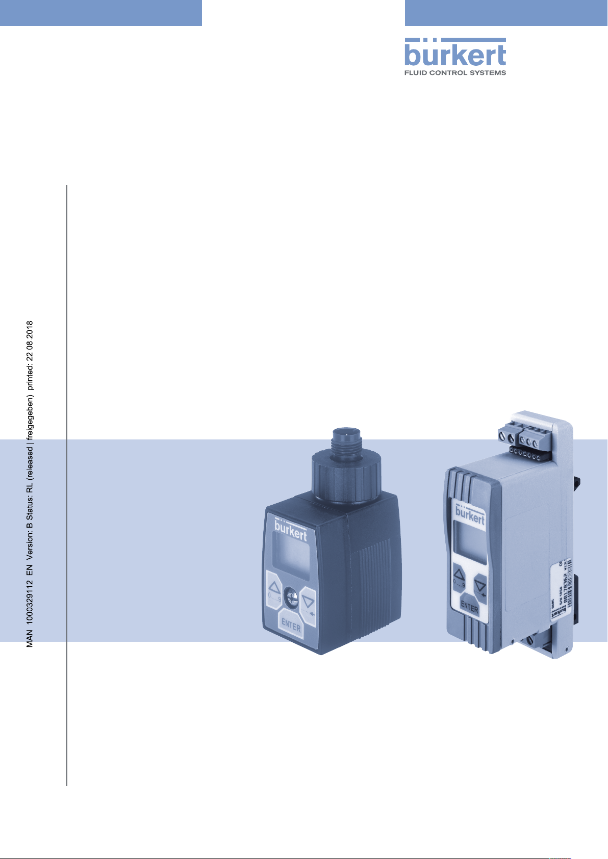
Type 8605
Digital Control Electronics for Proportional Valves
Page 2

We reserve the right to make technical changes without notice.
Technische Änderungen vorbehalten.
Sous réserve de modifications techniques.
© Bürkert Werke GmbH & Co. KG, 2007 - 2018
Operating Instructions 1804/05_EN-EN_00805613 / Original DE
Page 3
english
Type 8605
Digital Control Electronics Type 8605
Contents
1. OPERATING INSTRUCTIONS ........................................................................................................................................................5
1.1. Symbols
Definition of Term “Device” ...............................................................................................................................................5
1.2.
INTENDED USE ....................................................................................................................................................................................6
2.
BASIC SAFETY INSTRUCTIONS .................................................................................................................................................7
3.
GENERAL INFORMATION ................................................................................................................................................................8
4.
Contact address .....................................................................................................................................................................8
4.1.
4.2. Warranty
Information on the Internet ...............................................................................................................................................8
4.3.
PRODUCT DESCRIPTION ...............................................................................................................................................................9
5.
Field of Application ...............................................................................................................................................................9
5.1.
General Description ..............................................................................................................................................................9
5.2.
Form of the Device ................................................................................................................................................................9
5.3.
5.3.1. Type 8605 Cable plug version ............................................................................................................... 9
......................................................................................................................................................................................5
......................................................................................................................................................................................8
5.3.2. Type 8605 DIN rail version ....................................................................................................................10
TECHNICAL DATA .............................................................................................................................................................................11
6.
Operating Conditions ........................................................................................................................................................11
6.1.
CONFIGURATION AND FUNCTION ........................................................................................................................................12
7.
Operating and Display Elements ................................................................................................................................ 12
7.1.
7.1.1. Operating unit ..........................................................................................................................................12
7.1.2. LED’s during operation without operating unit .................................................................................13
Basic function .......................................................................................................................................................................13
7.2.
Adjustment to the Valve and Application Data ...................................................................................................14
7.3.
8. INSTALLATION
Safety instructions .............................................................................................................................................................16
8.1.
Electrical connections ......................................................................................................................................................16
8.2.
...................................................................................................................................................................................16
3
Page 4
english
Type 8605
8.2.1. Cable plug version ..................................................................................................................................16
8.2.2. DIN rail version .........................................................................................................................................18
9. CONFIGURATION
Operating modes ................................................................................................................................................................20
9.1.
Basic settings .......................................................................................................................................................................20
9.2.
Menu of the configuration mode ................................................................................................................................21
9.3.
9.3.1. InP (Input) - Selection of the input signal ..........................................................................................22
9.3.2. Out (Output) - Valve settings ............................................................................................................... 22
9.3.3. VAdJ (Valve adjust) - Fine tuning of the valve frequency ...............................................................25
9.3.4. AdJ (Adjust) - Adaptation of the coil current .................................................................................... 26
9.3.5. dELY (Delay) - Ramp function ..............................................................................................................27
9.3.6. Cut (Cut off) - Zero point cut off .........................................................................................................28
9.3.7. PArA (Parameter) - Controller setting ................................................................................................ 29
9.3.8. Addr (Address) - Interfaces ..................................................................................................................29
9.3.9. SPOS (Safe position) - Setting of the safety position ...................................................................30
9.3.10. dAtA (Data) - Upload and Download of parameters between the operating unit and the
basic device ..............................................................................................................................................30
9.3.11. END
.............................................................................................................................................................................20
............................................................................................................................................................................31
Factory Settings of the Control Electronics .........................................................................................................31
9.4.
10. MAINTENANCE
Safety Instructions .............................................................................................................................................................32
10.1.
10.2. Service
SPARE PARTS ....................................................................................................................................................................................33
11.
Ordering charts: Device variants ................................................................................................................................33
11.1.
11.2. Accessories
PACKAGING, TRANSPORT ..........................................................................................................................................................35
12.
13. STORAGE
13.1. Decommissioning
13.2. Restarting
14. DISPOSAL
..................................................................................................................................................................................32
......................................................................................................................................................................................32
............................................................................................................................................................................34
..............................................................................................................................................................................................35
...............................................................................................................................................................35
................................................................................................................................................................................35
............................................................................................................................................................................................36
4
Page 5
english
Type 8605
Operating Instructions
1. OPERATING INSTRUCTIONS
The operating instructions describe the entire life cycle of the device. Keep these instructions in a location which is
easily accessible to every user and make these instructions available to every new owner of the device.
WARNING!
The operating instructions contain important safety information!
Failure to observe these instructions may result in hazardous situations.
• The operating instructions must be read and understood.
1.1. Symbols
DANGER!
Warns of an immediate danger!
• Failure to observe the warning may result in a fatal or serious injury.
WARNING!
Warns of a potentially dangerous situation!
• Failure to observe the warning may result in serious injuries or death.
CAUTION!
Warns of a possible danger!
• Failure to observe the warning may result in moderately serious or minor injuries.
NOTE!
Warns of damage to property!
• Failure to observe the warning may result in damage to the device or the equipment.
Designates additional significant information, tips and recommendations.
Refers to information in these operating instructions or in other documentation.
→ designates a procedure which you must carry out.
1.2. Definition of Term “Device”
The term “device” used in these instructions always stands for the electromagnetic positioner type 8604.
5
Page 6

english
Type 8605
Intended Use
2. INTENDED USE
Non-intended use of the Type 8605 may be a hazard to people, nearby equipment and the environment.
• The device is designed for controlling Bürkert proportional valves.
• The device must not be exposed to direct sunlight.
• Do not use the device outdoors.
• To ensure that the device functions perfectly, set the PWM frequency which is suitable for the valve. A table
of set values can be found on the Bürkert homepage www.burkert.com → Type 8605.
• Use according to the authorized data, operating conditions and conditions of use specified in the contract
documents and operating instructions. These are described in the chapter entitled “6. Technical Data”.
• The device may be used only in conjunction with third-party devices and components recommended and
authorized by Bürkert.
• Correct transportation, correct storage and installation and careful use and maintenance are essential for reliable and faultless operation.
• Use the device only as intended.
6
Page 7
english
Type 8605
Basic Safety Instructions
3. BASIC SAFETY INSTRUCTIONS
These safety instructions do not make allowance for any:
• Contingencies and events which may arise during the installation, operation and maintenance of the devices.
• Local safety regulations – the operator is responsible for observing these regulations, also with reference to the
installation personnel.
Danger – high pressure!
• Before loosening the lines and valves, turn off the pressure and vent the lines.
Risk of electric shock!
• Before reaching into the device or the equipment, switch off the power supply and secure to prevent
reactivation!
• Observe applicable accident prevention and safety regulations for electrical equipment!
There is a risk of injury when the pressure drops in the system!
• Avoid pressure drops!
• Design the pressure supply system with as large a volume as possible, even with upline devices such as e. g.
pressure regulators, air conditioners, shut-off valves.
General hazardous situations.
To prevent injury, ensure that:
• That the system cannot be activated unintentionally.
• Installation and repair work may be carried out by authorised technicians only and with the appropriate tools.
• After an interruption in the power supply or pneumatic supply, ensure that the process is restarted in a defined
or controlled manner.
• The device may be operated only when in perfect condition and in consideration of the operating instructions.
• The general rules of technology apply to application planning and operation of the device.
NOTE!
Electrostatic sensitive components / modules!
The device contains electronic components which react sensitively to electrostatic discharge (ESD). Contact with
electrostatically charged persons or objects is hazardous to these components. In the worst case scenario, they
will be destroyed immediately or will fail after start-up.
• Observe the requirements in accordance with EN 61340-5-1 and 5-2 to minimise or avoid the possibility of
damage caused by sudden electrostatic discharge!
• Do not touch live electronic components!
The Type 8605 was developed with due consideration given to the accepted safety rules and are state-ofthe-art. Nevertheless, dangerous situations may occur.
Failure to observe this operating manual and its operating instructions as well as unauthorized tampering
with the device release us from any liability and also invalidate the warranty covering the devices and
accessories!
7
Page 8
english
Type 8605
General Information
4. GENERAL INFORMATION
4.1. Contact address
Germany
Bürkert Fluid Control Systems
Sales Center
Chr.-Bürkert-Str. 13-17
D-74653 Ingelfingen
Tel. + 49 (0) 7940 - 10 91 111
Fax + 49 (0) 7940 - 10 91 448
E-mail: info@de.buerkert.com
International
Contact addresses can be found on the final pages of the printed operating instructions.
And also on the Internet at:
www.burkert.com
4.2. Warranty
The warranty is only valid if the device is used as authorized in accordance with the specified application conditions.
4.3. Information on the Internet
Operating instructions and data sheet for Type 8605 can be found on the Internet at:
www.burkert.com
8
Page 9
english
Type 8605
Product description
5. PRODUCT DESCRIPTION
5.1. Field of Application
The Control Electronics, Type 8605, is designed for continuous operation in industrial environments, in particular in
the fields of open-loop and closed-loop control engineering.
5.2. General Description
The Digital Control Electronics for Proportional Valves, Type 8605 (hereinafter referred to as Control Electronics,
Type 8605) controls all Bürkert proportional valves with a max. current in the range from 40 to 2000 mA.
It transforms an external standard signal into a pulse-width modulated voltage signal (PWM) that is supplied to the
solenoid coil of the proportional valve.
A given value of the average coil current is thereby assigned to each value of the input signal. The proportional
opening of the valve can be set via the coil current.
5.3. Form of the Device
The Control Electronics is available in two forms.
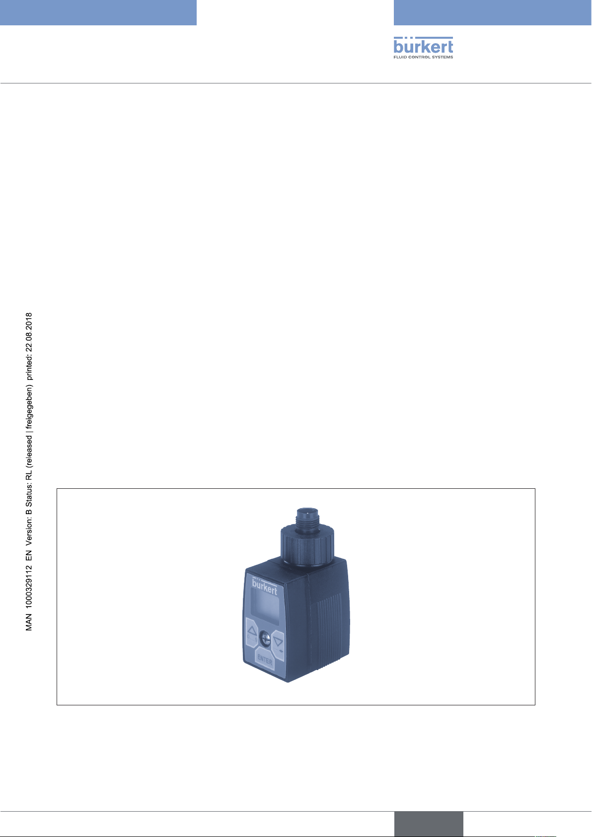
5.3.1. Type 8605 Cable plug version
Figure 1: Type 8605 Cable plug version
9
Page 10
english
Type 8605
Product description
Plug-in version on valves with connector pattern A:
e. g. types 2832, 2833, 2834, 2835, 2836,
2853,
2863, 2865,
2873, 2875
6022, 6023, 6024,
6223.
The operating unit can be removed after the setting process. During operation of the Control Electronics 8605 in
cable plug version without operating unit, the operating status is indicated by two LED’s.
Device variants:
• Variant 1 for valves with a max. current from 200 to 1000 mA
• Variant 2 for valves with a max. current from 500 to 2000 mA
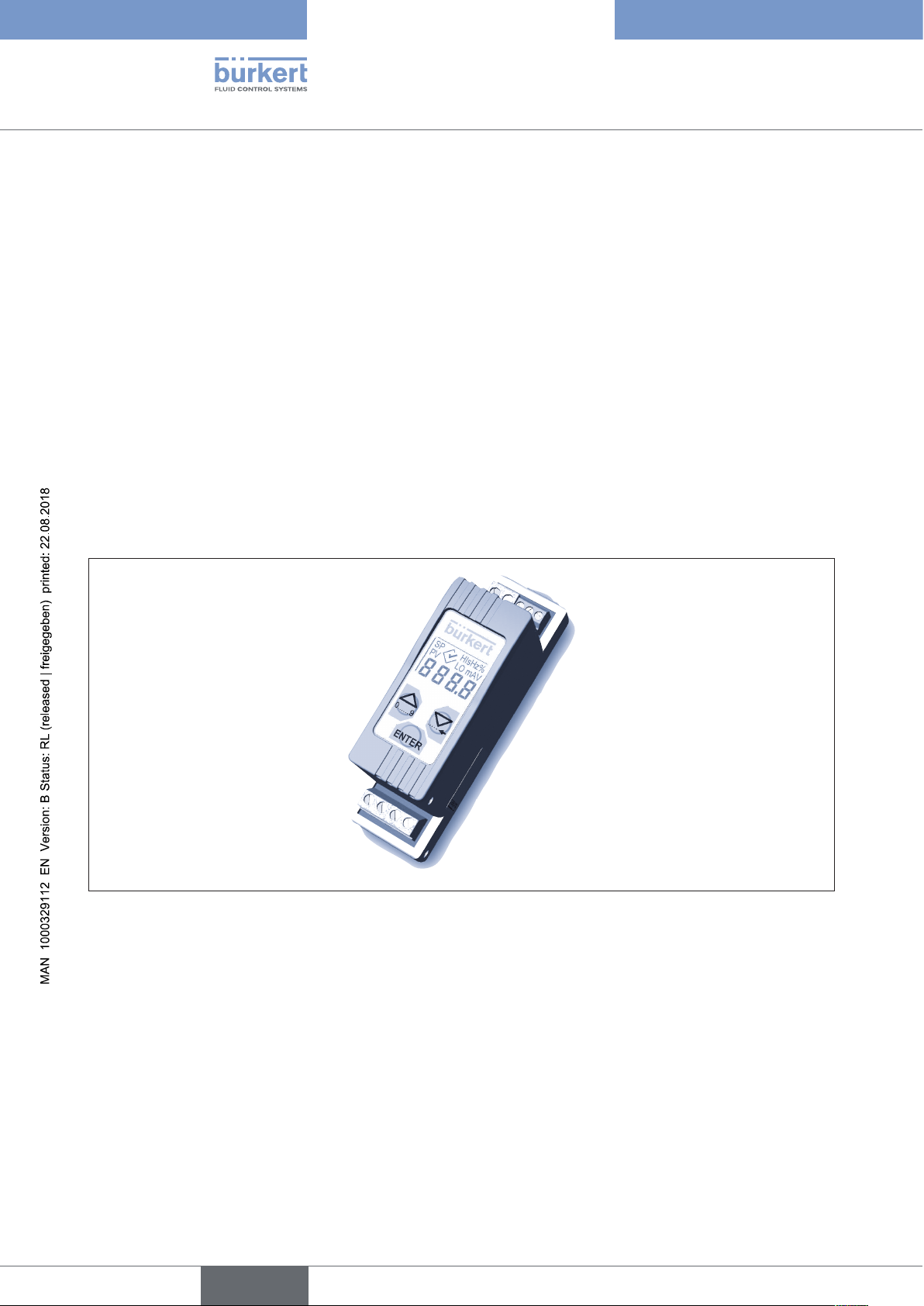
5.3.2. Type 8605 DIN rail version
10
Figure 2: Type 8605 DIN rail version
Separate electronics in housing for DIN rail mounting to DIN EN 50022. This form is suitable for all proportional
valves in the indicated current range. The operating unit cannot be removed.
Device variants:
• Variant 1 for valves with a max. current from 40 to 220 mA
• Variant 2 for valves with a max. current from 200 to 1000 mA
• Variant 3 for valves with a max. current from 500 to 2000 mA
Page 11
english
Type 8605
Technical Data
6. TECHNICAL DATA
6.1. Operating Conditions
WARNING!
The Type 8605 is not designed for use outdoors!
• Do not use the Type 8605 outdoors and avoid heat sources which may result in the permitted temperature
range to be exceeded.
Power supply 12...24V DC ± 10%
Residual ripple 5 %
Power consumption ca. 1 W
Output current (on the valve) max. 2 A
Operating temperature -10 ... 60º C / 14 ...140ºF
Interference resistance to EN50082-2
Emission to EN50081-2
Current range, depending
on the version for valves 40 ... 220 mA,
200 ... 1000 mA,
500 ... 2000 mA
Standard signal input
Voltage (0 ... 5, 0 ... 10 V) input impedance > 20 kW
Current (0 ...20, 4 ... 20 mA) input impedance <200 W
Housing: DIN rail version
Degree of protection IP40 (DIN EN 60529)
Materials Polyamide / PBT
Dimensions LxBxH: 97x27x57 mm
Housing: Cable plug version
Degree of protection IP65 (DIN EN 60529)
Materials Polyamide / PC
Dimensions LxBxH: 70x32x42.5 mm
11
Page 12
english
Type 8605
Configuration and Function
7. CONFIGURATION AND FUNCTION
7.1. Operating and Display Elements
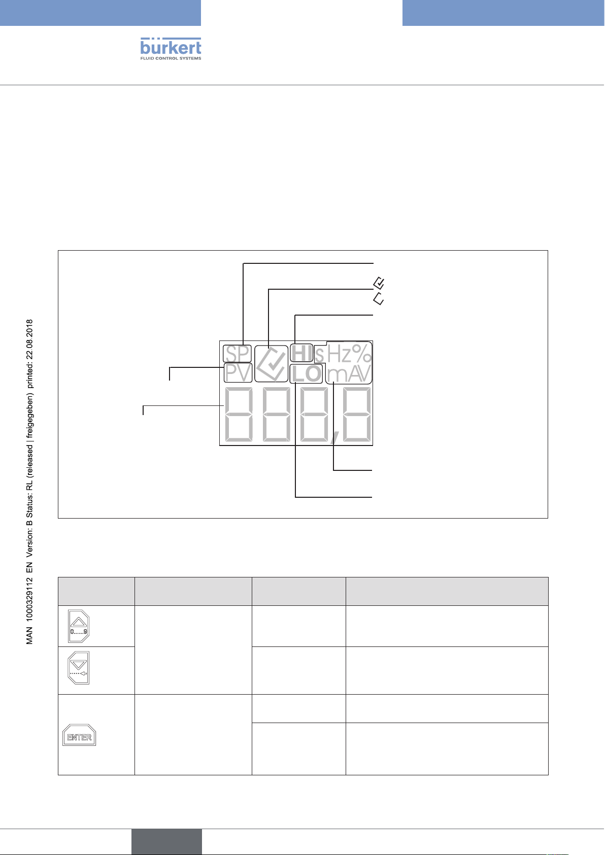
7.1.1. Operating unit
The operating unit consists of a LCD and keys. It is used for displays and settings of the Control Electronics, Type
8605.
Setpoint = Setpoint
(of the coil current)
= active
= not active
Upper limit
Process value = Actual value
(of the coil current)
LCD
Figure 3: Operating unit
Key assignment:
Key Display mode Configuration
Switch over the display
value
PV [mA] process value
PV [%] process value
SP [%] setpoint
TV [%] duty cycle
Scroll up
(selection)
Scroll down
(selection)
Unit of the displayed value
(s, Hz, %, mA, V)
Lower limit
Selected and confirmed menu item
mode
Increment (increase)
numerical values
Decrement (decrease)
numerical values
12
3 sec
Enter configuration mode
Confirm the
selected menu item
Switch between
main-menu and
sub-menu items
e. g.: Out-VALV
Select and deselect the individual menu
items
Confirm set values
Page 13

english
Type 8605
Configuration and Function
7.1.2. LED’s during operation without operating unit
During operation of the Control Electronics 8605 without operating unit, the operating status is indicated by two LED’s.
LED green: Device in operation
LED yellow: Current through valve
Figure 4: LED’s on version without operating unit
7.2. Basic function
The Control Electronics, Type 8605, is suitable for the control of all Bürkert proportional valves with a max. current
in the range from 40 to 2000 mA. It transforms an external standard signal into a pulse-width modulated voltage
signal (PWM) that is supplied to the solenoid coil of the proportional valve (see “Figure 5: Basic function of the
Control Electronics, Type 8605”). A given value of the average coil current is thereby assigned to each value of the
input signal. The proportional opening of the valve can be set via the coil current.
0 ... 5/10 V
0/4 ... 20 mA
Standard
1
Loadp
Figure 5: Basic function of the Control Electronics, Type 8605
0 to 5 V, 0 to 10 V, 0 to 20 mA or 4 to 20 mA can be set as standard signals.
13
Page 14

t
U
english
Type 8605
Configuration and Function
Due to the inductivity of the coil, the rectangular time curve of the PWM voltage signals is not transformed into a
corresponding current curve; instead the coil current has a sawtooth like „rounded“ time curve (see “Figure 6: Time
response of PWM voltage signal and coil current”). The mean (effective) coil current over time depends on the pulse
duty factor τ of the voltage signal.
τ = t
/(ton+ t
on
)
off
The curve of the coil current in the cycle of the PWM frequency generates a proportional change in the magnetic
force acting on the armature and hence, with an appropriate choice of this frequency (see chapter “7.3. Adjustment
to the Valve and Application Data”), a steady slight movement of the armature about its momentary equilibrium
position (dither movement). This avoids static friction effects at the bearing points.
t
off
I
Figure 6: Time response of PWM voltage signal and coil current
t
on
Due to the intrinsic heating of the coil and the associated large changes in resistance of the winding, the coil current
and hence the opening of the valve with a fixed pulse duty factor do not remain constant. An internal current control
system serves to compensate these thermal effects by corresponding tracking of the pulse duty factor.
7.3. Adjustment to the Valve and Application Data
The working range of a valve in a particular application depends greatly on its nominal size and the prevailing pressure
conditions.
In order to adapt the working range optimally to the range of the control signal, the key values for the effective coil
current are set via the operating unit in such a way that:
• the opening of the valve starts at a current value slightly above the lower key value (I1) and
• the full flow rate is achieved at a current value slightly below the upper key value (I2).
The lower key value is the current controlled at the lowest value of the standard signal (0 V, 0 mA or 4 mA).
The upper key value is obtained at the maximum value of the standard signal (5 V, 10 V or 20 mA).
Between the two key values, the effective coil current has a linear relationship to the input signal (see “Figure 7:
Current over standard signal”)
14
Page 15

2 % 100 %
t
english
Type 8605
Configuration and Function
I
I
2
I
1
Standard signal
Figure 7: Current over standard signal
The working range can also be scaled using the key values I1 and I2 in such a way that only a part of the full opening
of the valve is covered over the full range of the standard signal. In particular the flow rate range can be limited to a
smaller value than the valve would permit under the given pressure conditions.
The zero point cut-off guarantees the leak-tight closing of the valve at input signals below a given threshold of the
input signal (e.g. < 2 % of the limit value). In this case at values below this threshold, the coil current is set - in
deviation from the line shown in “Figure 7: Current over standard signal” - to zero so that the full force of the return
spring of the valve acts as a closing force.
The zero point cut-off can be optionally activated or deactivated.
ramp function serves to attenuate sudden changes in the input signal and to transform them into an adjustable ramp
A
(time constant 0 to 10 s) (see “Figure 8: Ramp function”). This is expedient for applications in which sudden changes
in the fluidic controlled variable are undesirable. The ramps can be set separately for positive and negative jumps.
The frequency of the PWM signal must be adapted to the valve used.
Standard signal
Current
Figure 8: Ramp function
The digital communication with superordinate controllers (PC’s, etc.) is possible via RS232 or RS485 interfaces
using auxiliary modules (see “11.1. Ordering charts: Device variants”).
15
Page 16

english
Type 8605
Installation
8. INSTALLATION
8.1. Safety instructions
DANGER!
Risk of injury from high pressure in the equipment!
• Before loosening the lines and valves, turn off the pressure and vent the lines.
Risk of injury due to electrical shock!
• Before reaching into the device or the equipment, switch off the power supply and secure to prevent
reactivation!
• Observe applicable accident prevention and safety regulations for electrical equipment!
WARNING!
Risk of injury from improper installation!
• Installation may be carried out by authorised technicians only and with the appropriate tools!
Risk of injury from unintentional activation of the system and an uncontrolled restart!
• Secure system from unintentional activation.
• Following assembly, ensure a controlled restart.
8.2. Electrical connections
DANGER!
Risk of injury due to electrical shock!
• Before reaching into the device or the equipment, switch off the power supply and secure to prevent
reactivation!
• Observe applicable accident prevention and safety regulations for electrical equipment!
8.2.1. Cable plug version
16
The electrical connection of the Controller Type 8605 in cable plug version is made via a 4-pin terminal strip inside
the device.
Cable:
• Diameter 6 ... 8 mm
• Cross-section max. 0.75 mm²
• Cable connections Cable gland or plug connector M12
4-pin
Page 17

english
Type 8605
Installation
Figure 9: Terminal strip connection
Standard signal (+)
12 . 24 V DC
Standard signal (-)
GND
12 . 24 V DC
GND
Figure 10: Plug connector connection
Standard signal (+)
Standard signal (-)
NOTE!
Ensure proper seating of the valve when screwing onto the valve (cable plug version)
Do not tighten the screw M3 too tightly (max. 0.3 Nm), as otherwise the housing will be deformed and proper
operation of the keys will no longer be possible.
17
Page 18

english
Type 8605
Installation
Tighten screw M3 to max. 0.3 Nm
Figure 11: Installation of the cable plug version on the valve
8.2.2. DIN rail version
The electrical connection of the Controller Type 8605 in DIN rail version is made via terminal strips.
Terminal strip Cable cross-section
2-pin for valve max. 1.5 mm²
3-pin for RS232- and RS485-interface max. 0.5 mm²
4-pin for voltage supply and standard signal max. 1.5 mm²
18
Page 19

english
Type 8605
Installation
1
2
3
4
Figure 12: Terminal strip connection
Legend:
1. 12 ... 24V DC
2. GND
3. Standard signal (-)
4. Standard signal (+)
5. Valve
5
6
7
8
9
6. Valve
7. RS485-B7T x D
8. RS485-A/R x D
9. GND
19
Page 20

9. CONFIGURATION
english
Type 8605
WARNING!
Danger may result from improper use!
Improper use can result in personal injury or damage to the device.
• The Control Electronics, Type 8605 may only be operated by qualified personnel.
NOTE!
Carry out the fluidic and electrical installation before starting the configuration.
9.1. Operating modes
Configuration
The Control Electronics can be operated in two modes:
• Display mode
• Configuration mode
After switching on the operating voltage, the Control Electronics, Type 8605 is in display mode.
Display mode
Configuration mode
3s
InP
Out
dELY
…
dAtA
End
20
Figure 13: Switching between display and configuration mode
9.2. Basic settings
Switch to the configuration mode to make the basic settings.
→ Hold the Enter key depressed for 3 seconds.
InP, the first menu item of the configuration menu, appears on the display.
→ Press the Enter key to make settings in the menu item InP.
Page 21

3 sec
english
Type 8605
Configuration
A sub-menu appears on the display.
You can switch between the sub-menu items by pressing the arrow keys and make the desired settings.
→ Confirm the desired setting by pressing the Enter key.
9.3. Menu of the configuration mode
Display mode
Input
Selection of the
input signal
Output
Valve settings
Delay
Ramp function
Cut off
Zero point cut off
Parameter
Settings Current
control
Address
Interface address
Figure 14: Menu of the configuration mode
Safe position
Safety setting
Data
Upload and Download
(only
Cable plug version)
End
Back to Display
mode
21
Page 22

english
Type 8605
Configuration
9.3.1. InP (Input) - Selection of the input signal
Enter the type of standard signal used in this menu item. You can select between the following standard signals:
• 0 ... 5 V,
• 0 ... 10 V,
• 0 ... 20 mA,
• 4 ... 20 mA.
Figure 15: InP (Input) - Selection of the input signal
9.3.2. Out (Output) - Valve settings
In this menu the electronics are adjusted to
• the valve used and
• the fluidic conditions in the application.
Absolutely vital are
• the setting of the valve type in the sub-menu VALV and
• the setting of the working range of the coil current in the sub-menu AdJ.
To ensure that the device functions perfectly, set the PWM frequency which is suitable for the valve.
• In the case of types 2871, 2873 and 2875 the PWM control frequencies must be adjusted in the VAdJ
submenu.
• In the case of special applications the PWM control frequency must be individually set in the VAdJ submenu.
If you have any queries, please contact your sales office or the Bürkert Technical Center. 24 h service
number: +49 (0) 7940 / 10 91 110
22
Set values for PWM frequencies:
A table of PWM frequencies which are suitable for controlling the valve type can be found on the Bürkert
homepage: www.burkert.com → Type 8605.
Page 23

english
Type 8605
Configuration
Figure 16: Out (output) - Valve setting
VALV (VALVE) - SETTING OF THE VALVE TYPE
CAUTION!
Danger from the selection of the wrong valve type!
The valve can be damaged if the wrong valve type is selected.
• Pay attention to the choice of the right valve type.
The Control Electronics, Type 8605, can be used for the whole range of Bürkert proportional valves. Depending on
the nominal sizes and fluidic performance data, the individual valve types contain solenoid coils with very different
sizes, winding data and dynamic properties (defined by the inductivity and Ohmic resistance).
The ability to react to a PWM voltage signal with a small dither movement and hence to give the valve a particularly
good response depends to a very great extent on the dynamic characteristic of the coil.
As a general rule of thumb it can be said that small coils with low magnetic force still react well even to higher
frequencies. At low frequencies, they even generate excessively large movement amplitudes and an unnecessarily
high noise level. Large coils with high magnetic force still generate dither movements only at low frequencies and
thus ensure sliding friction states.
The reaction of a valve to a PWM signal is dependent not only on its frequency but also on the current pulse duty
τ and the working point.
factor
The valve reacts more sensitively when the working point with average pulse duty factors [τ] and more slowly when
the opening corresponds to a pulse duty factor in the limit areas close to 0 % or close to 100 %. In order to compensate this dependence, control is effected with a PWM frequency that is dependent on the pulse duty factor
whose curve follows a triangular function (see “Figure 17: PWM frequency / pulse duty factor”). Here the frequency
is lowest at the limit points (0 %, 100 %), and highest at τ = 60 %.
23
Page 24

english
Type 8605
Configuration
f
f
HI
f
LO
0 %
60 %
100 %
τ
Figure 17: PWM frequency / pulse duty factor
The two limit frequencies of the PWM control (HI and LO) are set with the selection of the valve type. The frequency
output actually varies within this range, depending on the working point.
The following values (see “Figure 17: PWM frequency / pulse duty factor”) were determined empirically from the
behavior of a large number of individual devices of the corresponding type.
Type
24
Figure 18: Limit frequencies for Bürkert valve types
Set values for PWM frequencies:
A table of PWM frequencies which are suitable for controlling the valve type can be found on the Bürkert
homepage
www.burkert.com → Type 8605.
Page 25

english
Type 8605
Configuration
CAUTION!
Danger from wrong setting of the valve type.
If the selected valve type differs from the valve actually used whose coil has very different characteristics, the
function of the valve can be severely impaired. When using the flat spring valve, Type 2822, the input of a
wrong valve type can lead to irreparable device damage!
• Always set the valve type correctly. For this parameter, the value „----“ (no valve) is set as default value in the
delivery condition. If no valve is selected, the coil remains de-energised.
• In the case of types 2871, 2873 and 2875 the PWM frequency must be adjusted in addition to selecting the
type. A table of PWM frequencies which are suitable for controlling the valve type can be found on the Bürkert homepage: www.burkert.com → Type 8605.
The choice of valves depends on the device type being used
Due to the scatter of the valve types with respect to friction characteristics and the relationship between
sensitive control behavior and low hysteresis or low noise development and larger hysteresis, it can be
advisable to deviate from the recommended PWM frequencies (see also chapter “9.3.3. VAdJ (Valve
adjust) - Fine tuning of the valve frequency”).
9.3.3. VAdJ (Valve adjust) - Fine tuning of the valve frequency
In the menu VAdJ, the two frequencies defined with the selection of the valve type can be varied within certain limits.
A reduction of the values is generally associated with:
• a reduction in the hysteresis of the valve characteristic,
• improved response sensitivity and
• an increased noise level.
If the frequencies are increased, the hysteresis increases and the response sensitivity becomes poorer. The control
becomes slower and the noise level decreases.
Figure 19: VAdJ (Valve adjust) - Fine tuning of the valve frequency
25
Page 26

english
Type 8605
Configuration
• The following rule applies for the input of the frequency pairs: HI value > LO value
• In the menu item VALV, the HI and LO values are limited to an expedient range in relation to the valve
type. No normal control behaviour can be expected outside this range.
9.3.4. AdJ (Adjust) - Adaptation of the coil current
The working range of a proportional valve is defined by the coil current.
• Lower current limit - LO [mA]
Current value at which the valve just starts to open. This value corresponds to the nominal and actual value of
0 %. The setting range depends on the device version being used.
• Upper current limit - HI [mA]
Current value at which the valve just reaches the maximum flow rate. An increase in the coil current above the
upper value does not result in any noticeable increase in the flow rate. This value corresponds to the nominal
and actual value of 100 %. The setting range depends on the device version being used.
Current values outside the working range are irrelevant for a control. The range of the input standard signal (e. g.
0 to 10 V) is therefore set to the working range of the coil current (see chapter “7. Configuration and Function”).
• For a given valve type (coil version), the working range depends on the nominal size of the valve and on the
pressure ratios (inlet and return pressure) in the system. The setting has to be made under typical operating
conditions.
Figure 20: AdJ (Adjust) - Adaptation of the coil current
• A flow indicator is necessary for the setting of the working range. Determine the start and the achievement
of the maximum flow rate with this indicator.
26
• The absolute precision of the flow indicator is not crucial!
SETTING THE MINIMUM AND MAXIMUM COIL CURRENT
Start of flow
→ Set the minimum coil current I
(AdJ = LO mA) via the arrow keys so that the valve just starts to open.
1
Page 27

english
Type 8605
Configuration
→ Start with a current value at which the valve is still reliably closed and increase the coil current with the arrow
key until the flow indicator detects a flow for the first time.
→ Reduce the coil current by a few mA with the key until the valve is reliably closed again.
→ Confirm the minimum coil current I
with the -key.
1
Maximum flow rate
→ Set the maximum coil current I
(AdJ = HI mA) via the arrow keys so that the maximum flow rate is just
2
achieved.
→ Increase the coil current with the arrow key until the maximum flow rate is reached and a further increase in
the current does not result in a further increase in flow rate.
→ Reduce the coil current with the arrow key until the flow rate starts to drop noticeably again and confirm this
value with the -key as the maximum coil current I2 (AdJ = HI mA).
Indicative current values, depending on the valve type
For the current values of the start of opening and the maximum flow rate there are default values for each valve type
stored in the menu. These values are only indicated values depending on the nominal size of the valve and pressure
ratio.
In the menu item ADJ the valve must be set to the nominal size of the valve and the current pressure.
For all direct-acting proportional valves (i. e. all types with the exception of Type 6223), the current value I
start of opening drops with increasing inlet pressure; with an increasing pressure drop through the valve, the value
I2 at which the maximum flow rate is achieved also decreases.
For the pilot-controlled valve, Type 6223, the current value for the start of opening increase with increasing inlet
pressure; with an increasing pressure drop through the valve, the value I
also increases.
2
for the
1
9.3.5. dELY (Delay) - Ramp function
The ramp time for attenuating sudden changes in the input signal can be entered separately for changes upwards
and downwards.
• HI [s] - Ramp for a positive signal jump
The time indicated in seconds (0.1 to 10.0 s) relates to a change in set point from 0 % to 100 %.
• LO [s] - Ramp for a negative signal jump
The time indicated in seconds (0.1 to 10.0 s) relates to a change in set point from 100 % to 0 %.
With smaller changes in the input signal, the delay time corresponds to the set value multiplied by the size of the
change in percent. For example, with a sudden change from 20 % to 70 %, it corresponds to exactly half the
value set under HI in seconds. With a setting value of 0.0 s, the respective ramp function is deactivated.
27
Page 28

Figure 21: dELY (Delay) - Ramp function
english
Type 8605
Configuration
9.3.6. Cut (Cut off) - Zero point cut off
In order to guarantee leak-tight closing of the valve, the valve is completely de-energised with input signals below
the set limit (0.1 to 5.0 % of the set standard signal) when the zero point shutdown is active.
In addition to its control function, the valve can also take on the function of a cut-off valve.
Figure 22: Cut (Cut off) - Zero point cut off
• With a set value of 0.0 %, the zero point cut-off is deactivated. Even at an input signal of 0 %, the valve
no longer reliably shuts off the flow.
• The valve flow control restarts with a hysteresis of 0.5 %.
• The reactivation of the current controls starts as soon as the input signal is set to a value 0.5 % above
the defined threshold value; i. e. there is a hysteresis of 0.5 % for the activation and deactivation of the
cut off function
28
• The range of the input signal lying below the set threshold is no longer available for the current control
and fluidic flow control
Page 29

english
Type 8605
Configuration
9.3.7. PArA (Parameter) - Controller setting
The controlled coil current cannot follow changes in the input signal at any random speed.
Different sets of control parameters are stored for the internal current control. The controller dynamics can
therefore be set in three discrete steps between:
• very fast control with the probably occurrence of overswing behavior and
• slow control with a guaranteed elimination of overswing.
Set 1: slow
......
Set 3: fast
Figure 23: PArA (Parameter) - Controller setting
9.3.8. Addr (Address) - Interfaces
Setting of the bus address when using the serial interface (0 to 31).
Figure 24: Addr (Address) - Interfaces
29
Page 30

english
Type 8605
Configuration
9.3.9. SPOS (Safe position) - Setting of the safety position
Input of the safety position (0.0 to 100.0 %) that is controlled with a selected standard signal input of 4 to 20 mA
and a drop below the 4 mA input signal.
Figure 25: SPOS (Safe position) - Setting of the safety position
The standard signal 4 to 20 mA is the only one that permits a fault to be detected when the input value
drops below 4 mA. In this case it is possible to define which current value is to be controlled (e. g. 50 %)
9.3.10. dAtA (Data) - Upload and Download of parameters between the operating unit and the basic device
This function is used for data transfer from one operating unit to several basic devices. After connecting the operating
unit, the stored parameters can be transmitted to the basic device.
This function is only available for the cable plug version.
Figure 26: dAtA (Data)
uPLd (upload)
30
When upload is selected the parameters of the basic device are transferred to the operating unit. That means, that
first the memory of the operating unit is cleared and then filled with all relevant data of the basic device. After that
the operating unit displays „rdY“ (ready). If the data transfer failed „Err“ (error) is displayed.
Page 31

SP
%Hz
,
HI
s
english
Type 8605
Configuration
dnLd (download)
When download is selected the parameters stored in the operating unit are transferred to the basic device.
This is only possible, if the version of the data is the same as in the basic device (e. g. data transfer between a
200 - 1000 mA version and a 500 - 2000 mA version is not possible).
After that the operating unit displays “rdY”. If the data transfer failed “Err” is displayed.
9.3.11. END
To quit the respective menu level, select the menu item END with the arrow keys.
The settings made are saved on leaving the configuration menu.
PV
Figure 27: End
LO
mA
V
9.4. Factory Settings of the Control Electronics
Menu item Factory setting Comment
InP 0 ...10 V Input signal 0 ...10 V selected
Out / VALV - - - - No valve selected
Out / VAdJ OFF Manual fine tuning of the valve fre-
quency inactive
Out / AdJ LO: 2 mA
HI: 200 mA
deLY LO: 0.0 s
HI: 0.0 s
Cut LO: 2.0 % Zero point cut-off active at 2 %
These values are changed by a
valve selection
Ramp function inactive
PArA SEt2 Controller parameter set 2 selected
Addr 0 Address 0 for the serial communi-
cation selected
SPOS 0.0 % Safety setting 0 % at an input
signal below 4 mA (with selection
of the 4 ... 20 mA input signal)
selected
31
Page 32

english
Type 8605
Maintenance
10. MAINTENANCE
10.1. Safety Instructions
WARNING!
Danger due to improper maintenance work!
Improper maintenance may result in injuries as well as damage to the device and the surrounding area.
• Maintenance work may be carried out by authorised technicians only and with the appropriate tools!
Danger due to unintentional activation of the equipment!
Unintentional activation of the equipment during maintenance and repair work may result in injuries and / or
damage.
• Take appropriate measures to prevent the equipment from being unintentionally activated.
10.2. Service
When used in accordance with the instructions given in this operating manual, the Control Electronics Type 8605
is maintenance-free.
32
Page 33

english
Type 8605
Spare Parts
11. SPARE PARTS
CAUTION!
Danger due to incorrect accessories and replacement parts!
Incorrect accessories or unsuitable spare parts can result in injuries and in damage to the device and its
surroundings.
• Use only original accessories and original spare parts from Bürkert GmbH & Co. KG!
11.1. Ordering charts: Device variants
Design
Max.
coil current
range [mA]
Order no.:
2822 24V DC
2822 12V DC
2824 24V DC
2824 12V DC
2833 24V DC
2833 12V DC
2835 24V DC
2836 24V DC
2861 24V DC
2861 12V DC
2863 24V DC
2863 12V DC
2865 24V DC
2871 24V DC
2871 12V DC
2873 24V DC
2873 12V DC
2875 24V DC
6024 24V DC
6024 12V DC
6223 24V DC
6223 12V DC
Cable plug with PG
screw connection
Cable plug with
PG screw connection
without control unit
Cable plug with
M12 connection
Cable plug with
M12 connection
without control unit
Cable plug with PG
screw connection
Cable plug with
PG screw connection
without control unit
Cable plug with
M12 connection
Cable plug with
M12 connection
without control unit
DIN-rail
200 -
1000
178 354 178 358 178 355 178 359 178 356 178 360 178 357 178 361 178 362 178 363 178 364
X X X X X
X X X X X X X X X X
X X X X X X X X X X
X X X X X
X X X X X X X X X X
X X X X X X X X X X
X X X X X
X X X X X X X X X X
X X X X X X X X X X
X X X X X X X X X X
X X X X X
200 -
1000
200 -
1000
200 -
1000
500 -
2000
X X X X X
X X X X X
X X X X X
500 -
2000
500 -
2000
500 -
2000
40 -
220
X
X
X X
X X
X X
DIN-rail
200 -
1000
X
X
X
DIN-rail
500 -
2000
33
Page 34

english
Type 8605
Spare Parts
If two current ranges of the control electronics are possible choose the lower one
11.2. Accessories
Accessories / Individual parts Identification
Number
Operating unit for Type 8605 Cable plug 667 839
RS232 module for Type 8605 Cable plug 667 840
RS485 module for Type 8605 Cable plug 667 841
RS232 module for Type 8605 DIN Rail 667 842
RS485 module for Type 8605 DIN Rail 667 843
Angle-entry plug M12, 4pin 784 301
Connecting lead M12, 4-pin, 5 metres long 918 038
Connecting lead M8 for serial communication RS232 or RS485 918 718
Cap set (for operating without control unit) 670 549
34
Page 35

english
Type 8605
Packaging, Transport
12. PACKAGING, TRANSPORT
NOTE!
Transport damages!
Inadequately protected equipment may be damaged during transport.
• During transportation protect the device against wet and dirt in shock-resistant packaging.
• Avoid exceeding or dropping below the allowable storage temperature.
13. STORAGE
NOTE!
Incorrect storage may damage the device.
• Store the device in a dry and dust-free location!
• Storage temperature. -40 °C … +55 °C.
13.1. Decommissioning
Switch off the Control Electronics Type 8605 as follows:
→ Depressurize the system.
→ Switch off the power supply.
→ Remove the Control Electronics.
→ Keep the control electronics in the original packaging or in some other suitable packaging.
13.2. Restarting
Switch on the Control Electronics Type 8605 again as follows:
→ Unpack the Control Electronics and allow it to reach room temperature before switching on again.
→ Then proceed as described in chapter “8. Installation”.
35
Page 36

english
Type 8605
Packaging, Transport
14. DISPOSAL
→ Dispose of the device and packaging in an environmentally friendly manner.
NOTE!
Damage to the environment caused by device components contaminated with media.
• Observe applicable regulations on disposal and the environment.
Note:
Observe national waste disposal regulations.
36
Page 37

www.burkert.com
 Loading...